Embed Size (px)
Citation preview
Report No. 08C033R-RFCEP02V01-A
Page: 1 of 48
Test Report
Product Name Notebook
Model No. MS-1676, VR620
Transmitter Module. Atheros / AR5BXB63
Applicant MICRO-STAR INT’L Co., LTD.
Address No. 69, Li-De St., Jung-He City, Taipei Hsien, Taiwan, R.O.C.
Date of Receipt Nov. 28, 2008
Issued Date Dec. 15 , 2008
Report No. 08C033R-RFCEP02V01-A
Version V1.0
The Test Results relate only to the samples tested. The test report shall not be reproduced except in full without the written approval of QuieTek Corporation.
Report No. 08C033R-RFCEP02V01-A
Page: 2 of 48
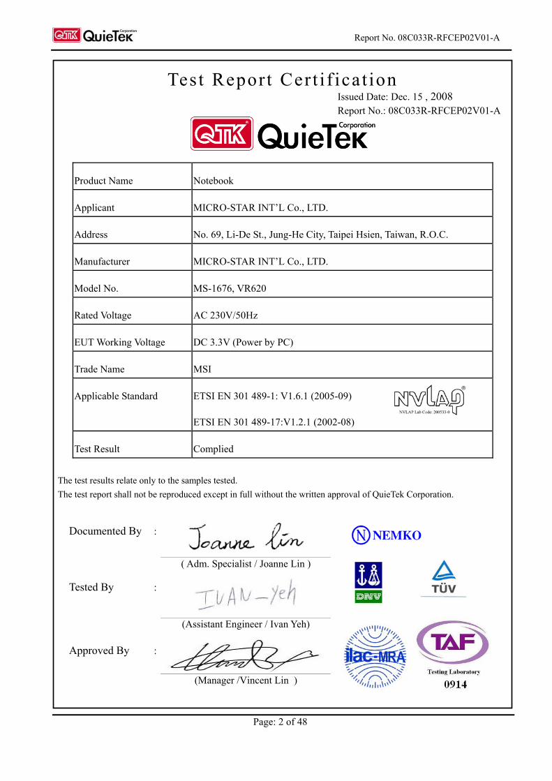
Test Report Cert i f icat ion Issued Date: Dec. 15 , 2008 Report No.: 08C033R-RFCEP02V01-A
Product Name Notebook
Applicant MICRO-STAR INT’L Co., LTD.
Address No. 69, Li-De St., Jung-He City, Taipei Hsien, Taiwan, R.O.C.
Manufacturer MICRO-STAR INT’L Co., LTD.
Model No. MS-1676, VR620
Rated Voltage AC 230V/50Hz
EUT Working Voltage DC 3.3V (Power by PC)
Trade Name MSI
Applicable Standard ETSI EN 301 489-1: V1.6.1 (2005-09)
ETSI EN 301 489-17:V1.2.1 (2002-08)
Test Result Complied
The test results relate only to the samples tested. The test report shall not be reproduced except in full without the written approval of QuieTek Corporation.
Documented By :
( Adm. Specialist / Joanne Lin )
Tested By :
(Assistant Engineer / Ivan Yeh)
Approved By :
(Manager /Vincent Lin )
Report No. 08C033R-RFCEP02V01-A
Page: 3 of 48
TABLE OF CONTENTS Description Page 1. GENERAL INFORMATION...............................................................................................5 1.1. EUT Description .....................................................................................................................5 1.2. Tested System Details .............................................................................................................7 1.3. Configuration of Test System..................................................................................................8 1.4. EUT Exercise Software...........................................................................................................8 1.5. Test Facility.............................................................................................................................9 2. Conducted Emission ...........................................................................................................10 2.1. Test Equipmen.......................................................................................................................10 2.2. Test Setup..............................................................................................................................10 2.3. Limits ....................................................................................................................................11 2.4. Test Procedure.......................................................................................................................12 2.5. Test Specification..................................................................................................................12 2.6. Uncertainty............................................................................................................................12 2.7. Test Result.............................................................................................................................12 3. Radiated Emission ..............................................................................................................13 3.1. Test Equipment .....................................................................................................................13 3.2. Test Setup..............................................................................................................................13 3.3. Limits ....................................................................................................................................14 3.4. Test Procedure.......................................................................................................................14 3.5. Test Specification..................................................................................................................14 3.6. Uncertainty............................................................................................................................14 3.7. Test Result.............................................................................................................................14 4. Power Harmonics, Voltage Fluctuation and Flicker........................................................15 4.1. Test Equipment .....................................................................................................................15 4.2. Test Setup..............................................................................................................................15 4.3. Limits ....................................................................................................................................15 4.4. Test Procedure.......................................................................................................................16 4.5. Test Specification..................................................................................................................16 4.6. Uncertainty............................................................................................................................16 4.7. Test Result.............................................................................................................................16 5. Electrostatic Discharge (ESD)............................................................................................17 5.1. Test Equipment .....................................................................................................................17 5.2. Test Setup..............................................................................................................................17 5.3. Test Level..............................................................................................................................17 5.4. Test Procedure.......................................................................................................................18 5.5. Test Specification..................................................................................................................18 5.6. Uncertainty............................................................................................................................18 5.7. Test Result.............................................................................................................................18 6. Radiated Susceptibility (RS) ..............................................................................................19 6.1. Test Equipment .....................................................................................................................19 6.2. Test Setup..............................................................................................................................19 6.3. Test Level..............................................................................................................................19 6.4. Test Procedure.......................................................................................................................20 6.5. Test Specification..................................................................................................................20 6.6. Uncertainty............................................................................................................................20 6.7. Test Result.............................................................................................................................20 7. Electrical Fast Transient/Burst (EFT/B)...........................................................................21 7.1. Test Equipment .....................................................................................................................21
Report No. 08C033R-RFCEP02V01-A
Page: 4 of 48
7.2. Test Setup..............................................................................................................................21 7.3. Test Level..............................................................................................................................22 7.4. Test Procedure.......................................................................................................................22 7.5. Test Specification..................................................................................................................22 7.6. Uncertainty............................................................................................................................22 7.7. Test Result.............................................................................................................................22 8. Surge.....................................................................................................................................23 8.1. Test Equipment .....................................................................................................................23 8.2. Test Setup..............................................................................................................................23 8.3. Test Level..............................................................................................................................23 8.4. Test Procedure.......................................................................................................................24 8.5. Test Specification..................................................................................................................24 8.6. Uncertainty............................................................................................................................24 8.7. Test Result.............................................................................................................................24 9. Conducted Susceptibility (CS) ...........................................................................................25 9.1. Test Equipment .....................................................................................................................25 9.2. Test Setup..............................................................................................................................25 9.3. Test Level..............................................................................................................................25 9.4. Test Procedure.......................................................................................................................26 9.5. Test Specification..................................................................................................................26 9.6. Uncertainty............................................................................................................................26 9.7. Test Result.............................................................................................................................26 10. Voltage Dips and Interruption ...........................................................................................27 10.1. Test Equipment .....................................................................................................................27 10.2. Test Setup..............................................................................................................................27 10.3. Test Level..............................................................................................................................27 10.4. Test Procedure.......................................................................................................................28 10.5. Test Specification..................................................................................................................28 10.6. Uncertainty............................................................................................................................28 10.7. Test Result.............................................................................................................................28 11. EMC Reduction Method During Compliance Testing.....................................................29 12. Test Result............................................................................................................................30 12.1. Test Data of Conducted Emission.........................................................................................31 12.2. Test Data of Radiated Emission ............................................................................................37 12.3. Test Data of Power Harmonics, Voltage Flucturation and Flicker........................................38 12.4. Test Data of Electrostatic Discharge .....................................................................................41 12.5. Test Data of Radiated Susceptibility.....................................................................................42 12.6. Test Data of Electrical Fast Transient ...................................................................................43 12.7. Test Data of Surge.................................................................................................................44 12.8. Test Data of Conducted Susceptibility..................................................................................45 12.9. Test Data of Voltage Dips and Interruption...........................................................................46
Attachment 1: EUT Test Photographs
Attachment 2: EUT Detailed Photographs
Report No. 08C033R-RFCEP02V01-A
Page: 5 of 48
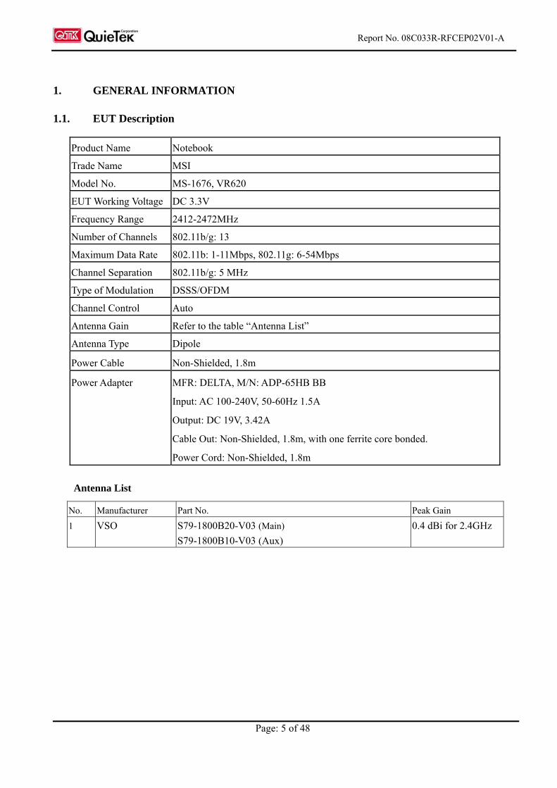
1. GENERAL INFORMATION
1.1. EUT Description
Product Name Notebook
Trade Name MSI
Model No. MS-1676, VR620
EUT Working Voltage DC 3.3V
Frequency Range 2412-2472MHz
Number of Channels 802.11b/g: 13
Maximum Data Rate 802.11b: 1-11Mbps, 802.11g: 6-54Mbps
Channel Separation 802.11b/g: 5 MHz
Type of Modulation DSSS/OFDM
Channel Control Auto
Antenna Gain Refer to the table “Antenna List”
Antenna Type Dipole
Power Cable Non-Shielded, 1.8m
Power Adapter MFR: DELTA, M/N: ADP-65HB BB
Input: AC 100-240V, 50-60Hz 1.5A
Output: DC 19V, 3.42A
Cable Out: Non-Shielded, 1.8m, with one ferrite core bonded.
Power Cord: Non-Shielded, 1.8m
Antenna List
No. Manufacturer Part No. Peak Gain
1 VSO S79-1800B20-V03 (Main)
S79-1800B10-V03 (Aux)
0.4 dBi for 2.4GHz
Report No. 08C033R-RFCEP02V01-A
Page: 6 of 48
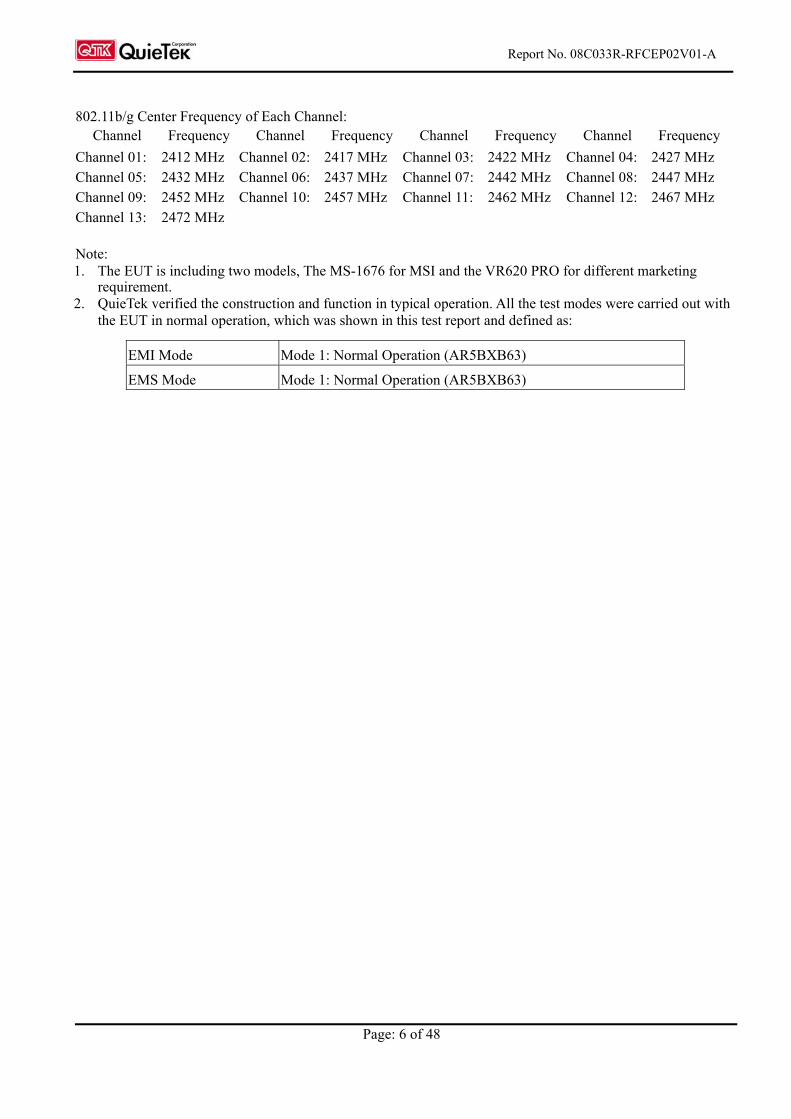
802.11b/g Center Frequency of Each Channel:
Channel Frequency Channel Frequency Channel Frequency Channel Frequency
Channel 01: 2412 MHz Channel 02: 2417 MHz Channel 03: 2422 MHz Channel 04: 2427 MHz Channel 05: 2432 MHz Channel 06: 2437 MHz Channel 07: 2442 MHz Channel 08: 2447 MHz Channel 09: 2452 MHz Channel 10: 2457 MHz Channel 11: 2462 MHz Channel 12: 2467 MHz Channel 13: 2472 MHz Note: 1. The EUT is including two models, The MS-1676 for MSI and the VR620 PRO for different marketing
requirement. 2. QuieTek verified the construction and function in typical operation. All the test modes were carried out with
the EUT in normal operation, which was shown in this test report and defined as:
EMI Mode Mode 1: Normal Operation (AR5BXB63)
EMS Mode Mode 1: Normal Operation (AR5BXB63)
Report No. 08C033R-RFCEP02V01-A
Page: 7 of 48
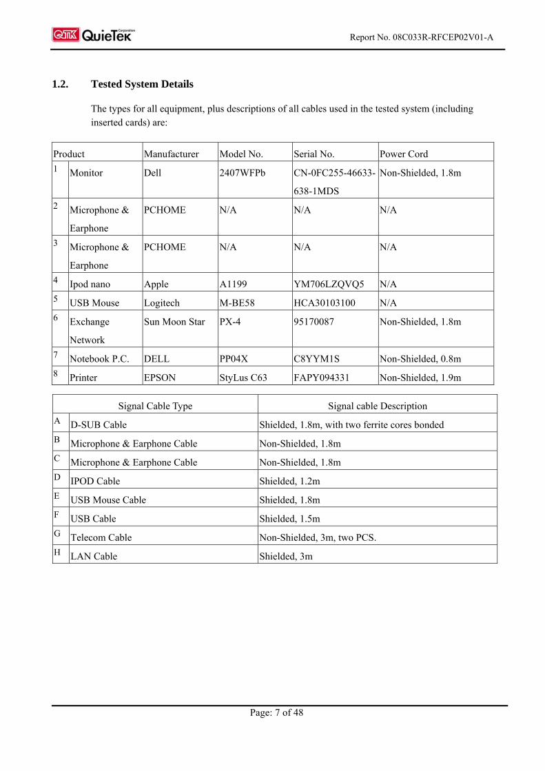
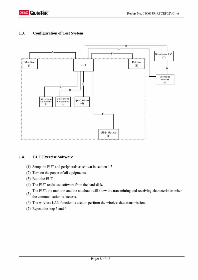
1.2. Tested System Details
The types for all equipment, plus descriptions of all cables used in the tested system (including inserted cards) are:
Product Manufacturer Model No. Serial No. Power Cord
1 Monitor Dell 2407WFPb CN-0FC255-46633-
638-1MDS
Non-Shielded, 1.8m
2 Microphone &
Earphone
PCHOME N/A N/A N/A
3 Microphone &
Earphone
PCHOME N/A N/A N/A
4 Ipod nano Apple A1199 YM706LZQVQ5 N/A
5 USB Mouse Logitech M-BE58 HCA30103100 N/A
6 Exchange
Network
Sun Moon Star PX-4 95170087 Non-Shielded, 1.8m
7 Notebook P.C. DELL PP04X C8YYM1S Non-Shielded, 0.8m
8 Printer EPSON StyLus C63 FAPY094331 Non-Shielded, 1.9m
Signal Cable Type Signal cable Description
A D-SUB Cable Shielded, 1.8m, with two ferrite cores bonded
B Microphone & Earphone Cable Non-Shielded, 1.8m
C Microphone & Earphone Cable Non-Shielded, 1.8m
D IPOD Cable Shielded, 1.2m
E USB Mouse Cable Shielded, 1.8m
F USB Cable Shielded, 1.5m
G Telecom Cable Non-Shielded, 3m, two PCS.
H LAN Cable Shielded, 3m
Report No. 08C033R-RFCEP02V01-A
Page: 8 of 48
1.3. Configuration of Test System
1.4. EUT Exercise Software
(1) Setup the EUT and peripherals as shown in section 1.3.
(2) Turn on the power of all equipments.
(3) Boot the EUT.
(4) The EUT reads test software from the hard disk.
(5) The EUT, the monitor, and the notebook will show the transmitting and receiving characteristics when
the communication is success.
(6) The wireless LAN function is used to perform the wireless data transmission.
(7) Repeat the step 5 and 6.
Report No. 08C033R-RFCEP02V01-A
Page: 9 of 48
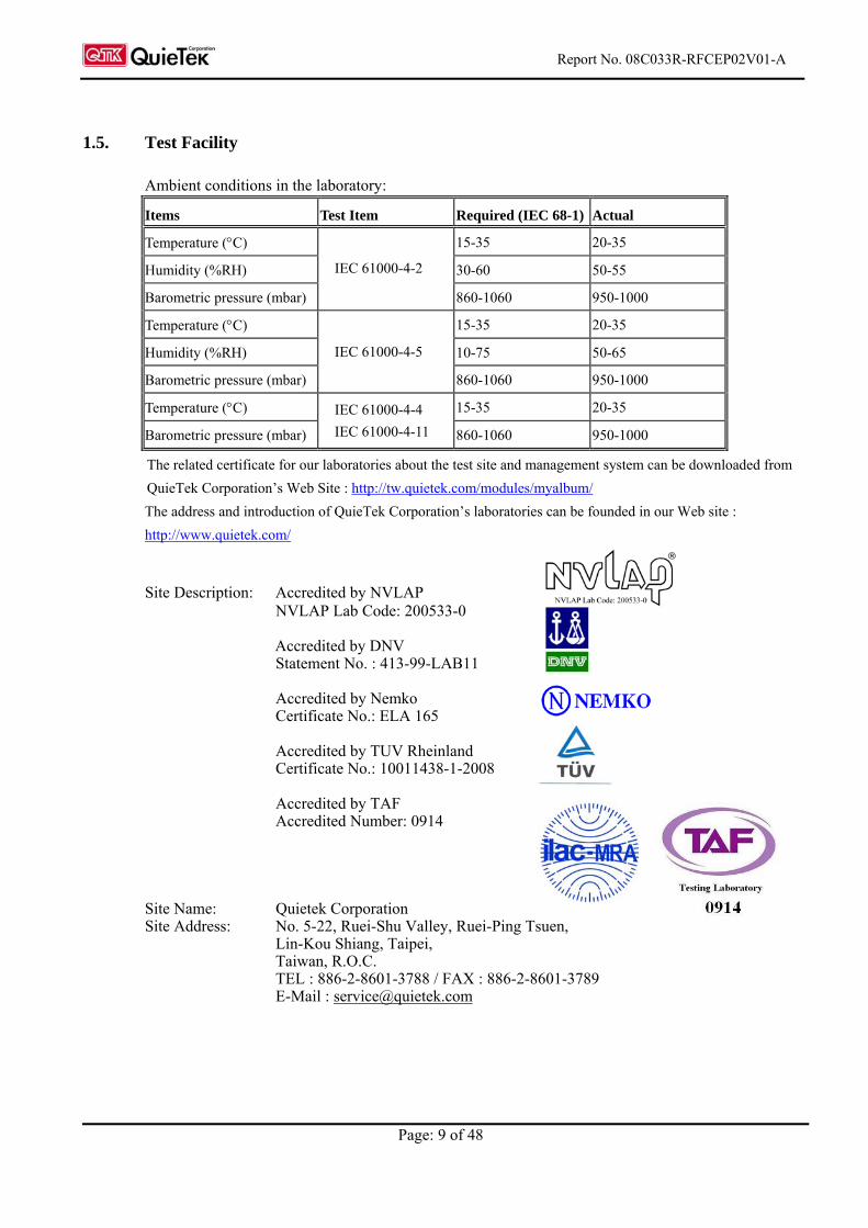
1.5. Test Facility
Ambient conditions in the laboratory:
Items Test Item Required (IEC 68-1) Actual
Temperature (C) 15-35 20-35
Humidity (%RH) 30-60 50-55
Barometric pressure (mbar)
IEC 61000-4-2
860-1060 950-1000
Temperature (C) 15-35 20-35
Humidity (%RH) 10-75 50-65
Barometric pressure (mbar)
IEC 61000-4-5
860-1060 950-1000
Temperature (C) 15-35 20-35
Barometric pressure (mbar)
IEC 61000-4-4
IEC 61000-4-11 860-1060 950-1000
The related certificate for our laboratories about the test site and management system can be downloaded from
QuieTek Corporation’s Web Site : http://tw.quietek.com/modules/myalbum/
The address and introduction of QuieTek Corporation’s laboratories can be founded in our Web site :
http://www.quietek.com/
Site Description: Accredited by NVLAP NVLAP Lab Code: 200533-0 Accredited by DNV Statement No. : 413-99-LAB11 Accredited by Nemko Certificate No.: ELA 165 Accredited by TUV Rheinland Certificate No.: 10011438-1-2008 Accredited by TAF Accredited Number: 0914 Site Name: Quietek Corporation Site Address: No. 5-22, Ruei-Shu Valley, Ruei-Ping Tsuen, Lin-Kou Shiang, Taipei, Taiwan, R.O.C. TEL : 886-2-8601-3788 / FAX : 886-2-8601-3789 E-Mail : [email protected]
Report No. 08C033R-RFCEP02V01-A
Page: 10 of 48
2. Conducted Emission
2.1. Test Equipmen
The following test equipment are used during the conducted emission test:
Item Equipment Manufacturer Model No. / Serial No. Last Cal. Remark
1 Test Receiver R & S ESCS 30 / 825442/018 Sep., 2008
2 Artificial Mains Network R & S ENV4200 / 848411/10 Feb., 2008 Peripherals
3 LISN R & S ESH3-Z5 / 825562/002 Feb., 2008 EUT
4 Pulse Limiter R & S ESH3-Z2 / 357.8810.52 Feb., 2008
5 4-wire ISN R & S ENY41 / 837032/001 Feb., 2008
6 Double 2-Wire ISN R & S ENY22 / 835354/008 Feb., 2008
7 No.1 Shielded Room
Note: All equipments are calibrated every one year.
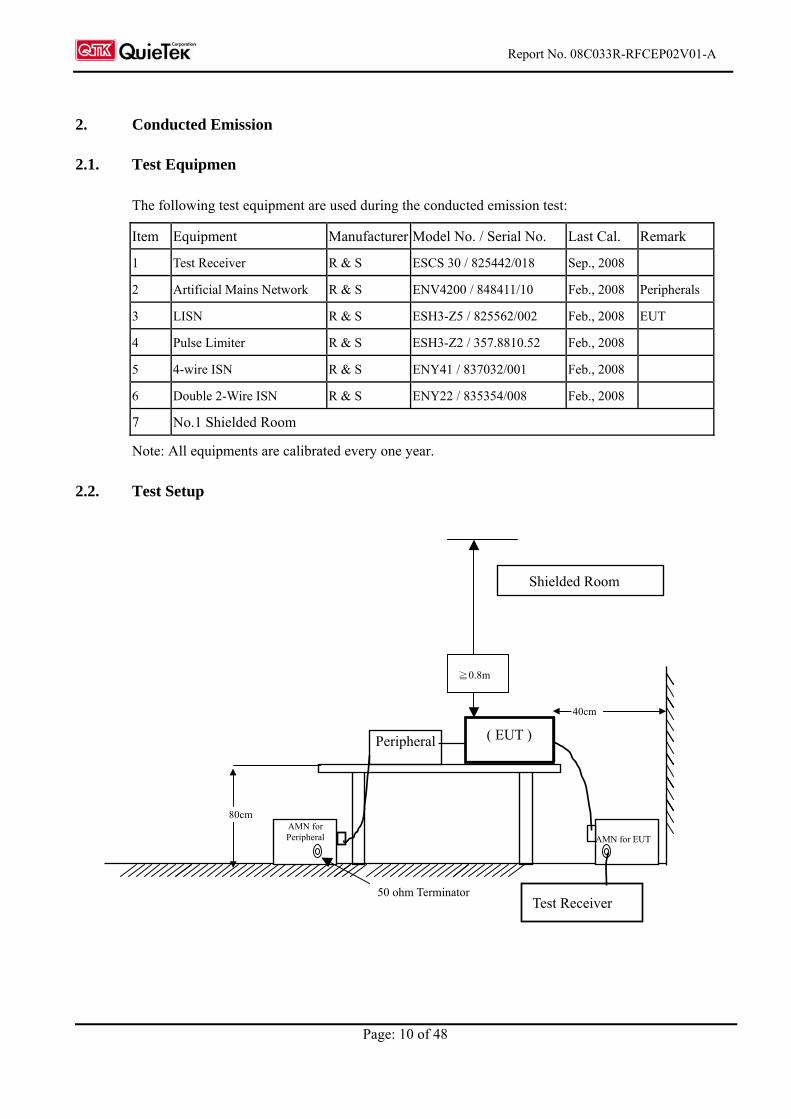
2.2. Test Setup
Peripheral
80cm
AMN for EUT
Shielded Room
40cm
( EUT )
≧0.8m
AMN for Peripheral
50 ohm Terminator Test Receiver
Report No. 08C033R-RFCEP02V01-A
Page: 11 of 48
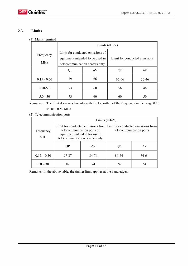
2.3. Limits
(1) Mains terminal
Limits (dBuV)
Limit for conducted emissions of
equipment intended to be used in
telecommunication centers only
Limit for conducted emissions Frequency
MHz
QP AV QP AV
0.15 - 0.50 79 66 66-56 56-46
0.50-5.0 73 60 56 46
5.0 - 30 73 60 60 50
Remarks: The limit decreases linearly with the logarithm of the frequency in the range 0.15
MHz ~ 0.50 MHz.
(2) Telecommunication ports
Limits (dBuV)
Limit for conducted emissions from telecommunication ports of
equipment intended for use in telecommunication centers only
Limit for conducted emissions from telecommunication ports Frequency
MHz
QP AV QP AV
0.15 – 0.50 97-87 84-74 84-74 74-64
5.0 – 30 87 74 74 64
Remarks: In the above table, the tighter limit applies at the band edges.
Report No. 08C033R-RFCEP02V01-A
Page: 12 of 48
2.4. Test Procedure
AC Mains:
The EUT and simulators are connected to the main power through a line impedance stabilization
network (L.I.S.N.). This provides a 50 ohm /50uH coupling impedance for the measuring equipment.
The peripheral devices are also connected to the main power through a LISN that provides a 50ohm
/50uH coupling impedance with 50ohm termination. (Please refers to the block diagram of the test
setup and photographs.)
Both sides of AC line are checked for maximum conducted interference. In order to find the maximum
emission, the relative positions of equipment and all of the interface cables must be changed according
to ETSI EN 301 489-1: V1.6.1 (2005-09) on conducted measurement.
The bandwidth of the field strength meter (R & S Test Receiver ESCS 30) is set at 9kHz.
Telecommunication Port:
The mains voltage shall be supplied to the EUT via the LISN when the measurement of
telecommunication port is performed. The common mode disturbances at the telecommunication port
shall be connected to the ISN, which is 150ohm impedance. Both alternative cables are tested related to
the LCL requested. The measurement range is from 150kHz to 30MHz. The bandwidth of measurement
is set to 9kHz. The 60dB LCL ISN is used for cat. 5 cable, 50dB LCL ISN is used for cat. 3 and 80dB
LCL is wed for alternative one.
2.5. Test Specification
According to ETSI EN 301 489-1: V1.6.1 (2005-09)
EN 55022:2006
2.6. Uncertainty
± 2.26 dB
2.7. Test Result
The emission from the EUT was below the specified limits. The worst-case emissions are shown in
section 12. The EUT complies the acceptance criterion and passes the test.
Report No. 08C033R-RFCEP02V01-A
Page: 13 of 48
3. Radiated Emission
3.1. Test Equipment
The following test equipment are used during the Radiated emission test:
Test Site Equipment Manufacturer Model No./Serial No. Last Cal.
Test Receiver R & S ESVS 10 / 834468/003 July, 2008
Spectrum Analyzer Advantest R3162/ 00803480 May, 2008
Pre-Amplifier Advantest BB525C/ 3307A01812 May, 2008
Site # 1
Bilog Antenna SCHAFFNER CBL6112B / 2697 Nov., 2008
Test Receiver R & S ESCS 30 / 836858 / 022 Nov., 2008
Spectrum Analyzer Advantest R3162 / 100803466 May, 2008
Pre-Amplifier Advantest BB525C/3307A01814 May, 2008
Bilog Antenna SCHAFFNER CBL6112B / 2705 Oct., 2008
Horn Antenna ETS 3115 / 0005-6160 July, 2008
Site # 2
Pre-Amplifier QTK QTK-AMP-01/ 0001 July, 2008
Test Receiver R & S ESI 26 / 838786 / 004 May, 2008
Spectrum Analyzer Advantest R3162 / 100803480 May, 2008
Pre-Amplifier QTK QTK-AMP-03 / 0003 May, 2008
Bilog Antenna SCHAFFNER CBL6112B / 2697 May, 2008
Horn Antenna ETS 3115 / 0005-6160 July, 2008
Site # 3
Pre-Amplifier QTK QTK-AMP-01 / 0001 July, 2008
Note: 1. All equipments are calibrated every one year.
2. The test instruments marked by “X” are used to measure the final test results.
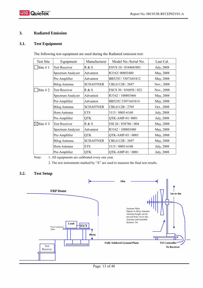
3.2. Test Setup
EUT
FRP Dome
Test Receiver
Antenna Mast Dipole or Horn Antenna Antenna height can be moved from 1m to 4m, Antenna and turntable distance 3m
TO Controller
To Receiver
Fully Soldered Ground Plane
Non-Conducted Table
10m
1m to 4m
80cm
Load
Report No. 08C033R-RFCEP02V01-A
Page: 14 of 48
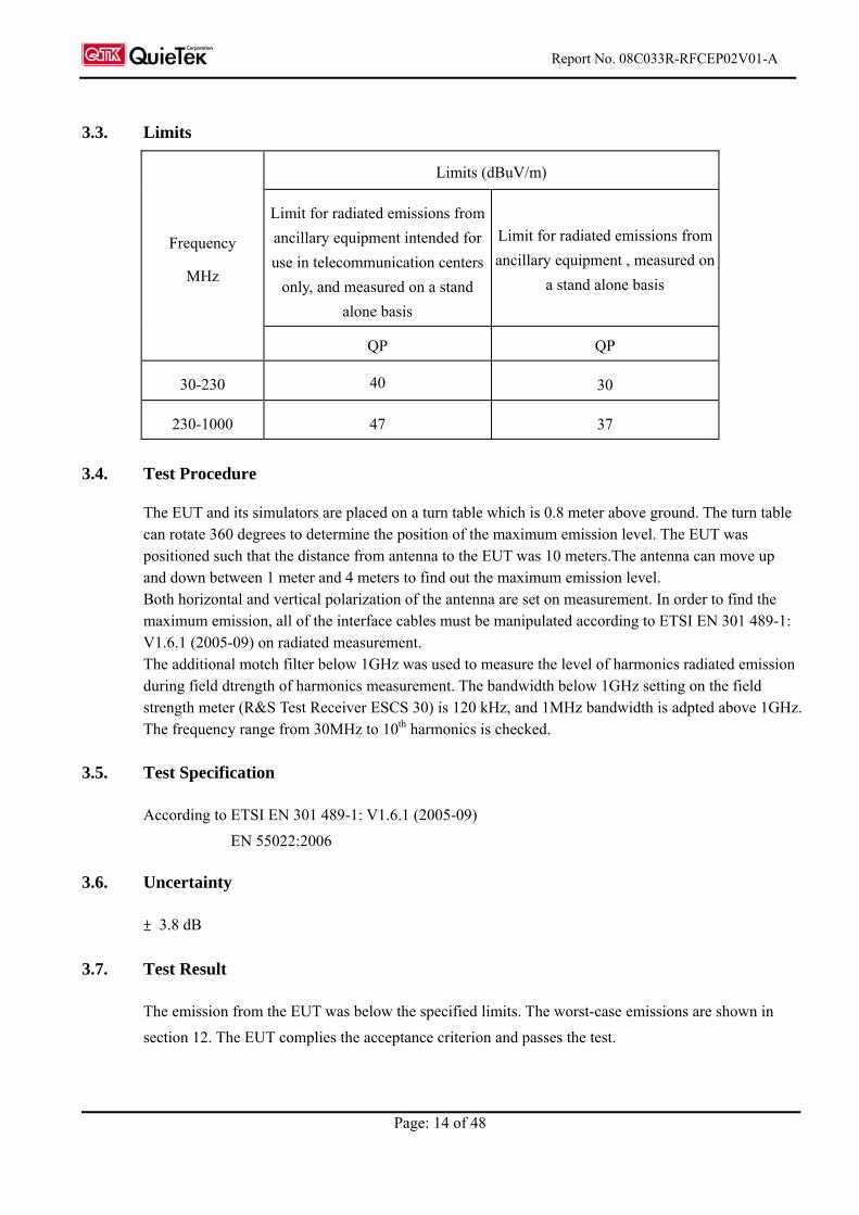
3.3. Limits
Limits (dBuV/m)
Limit for radiated emissions from
ancillary equipment intended for
use in telecommunication centers
only, and measured on a stand
alone basis
Limit for radiated emissions from
ancillary equipment , measured on
a stand alone basis
Frequency
MHz
QP QP
30-230 40 30
230-1000 47 37
3.4. Test Procedure
The EUT and its simulators are placed on a turn table which is 0.8 meter above ground. The turn table can rotate 360 degrees to determine the position of the maximum emission level. The EUT was positioned such that the distance from antenna to the EUT was 10 meters.The antenna can move up and down between 1 meter and 4 meters to find out the maximum emission level. Both horizontal and vertical polarization of the antenna are set on measurement. In order to find the maximum emission, all of the interface cables must be manipulated according to ETSI EN 301 489-1: V1.6.1 (2005-09) on radiated measurement. The additional motch filter below 1GHz was used to measure the level of harmonics radiated emission during field dtrength of harmonics measurement. The bandwidth below 1GHz setting on the field strength meter (R&S Test Receiver ESCS 30) is 120 kHz, and 1MHz bandwidth is adpted above 1GHz. The frequency range from 30MHz to 10th harmonics is checked.
3.5. Test Specification
According to ETSI EN 301 489-1: V1.6.1 (2005-09)
EN 55022:2006
3.6. Uncertainty
± 3.8 dB
3.7. Test Result
The emission from the EUT was below the specified limits. The worst-case emissions are shown in
section 12. The EUT complies the acceptance criterion and passes the test.
Report No. 08C033R-RFCEP02V01-A
Page: 15 of 48
4. Power Harmonics, Voltage Fluctuation and Flicker
4.1. Test Equipment
Item Instrument 4Manufacturer Type No/Serial No. Last Calibration
1 Power Harmonics
Tester
SCHAFFNER Profline 2105-400
S/N: HK54148
June, 2008
2 Analyzer SCHAFFNER CCN 1000-1/X71887 June, 2008
3 No.3 Shielded Room
Note: All equipments are calibrated every one year.
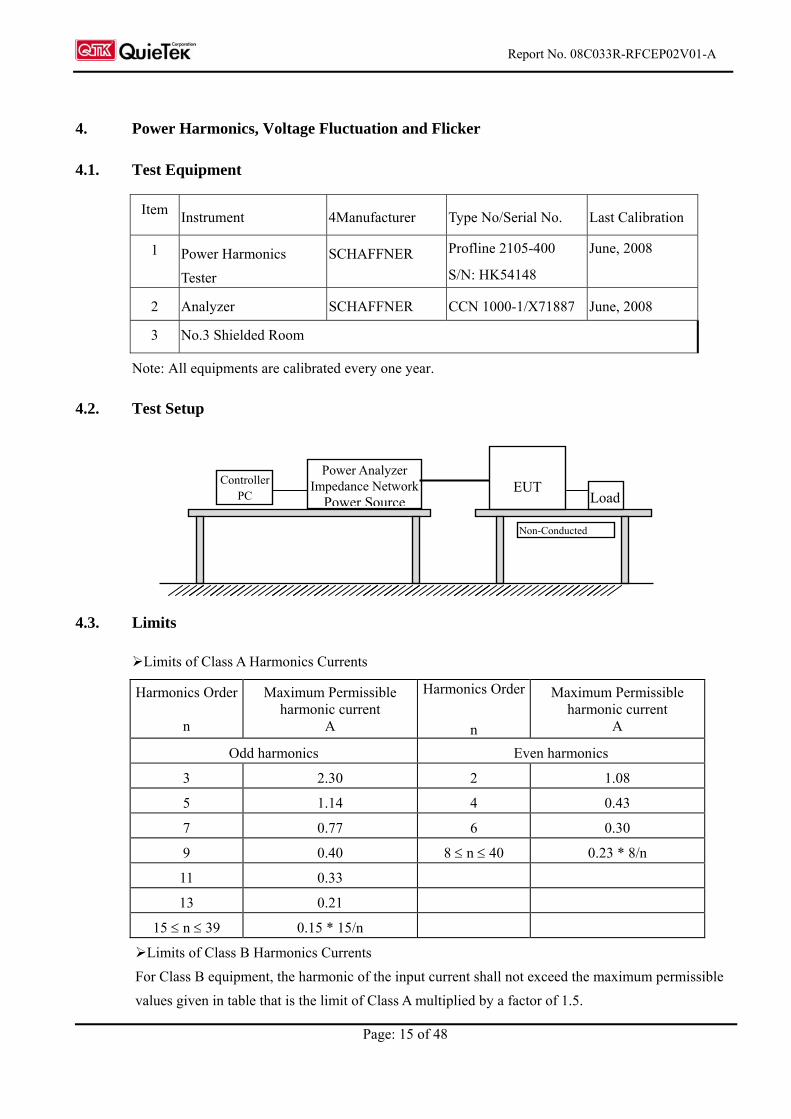
4.2. Test Setup
4.3. Limits
Limits of Class A Harmonics Currents
Harmonics Order
n
Maximum Permissible harmonic current
A
Harmonics Order
n
Maximum Permissible harmonic current
A
Odd harmonics Even harmonics
3 2.30 2 1.08
5 1.14 4 0.43
7 0.77 6 0.30
9 0.40 8 n 40 0.23 * 8/n
11 0.33
13 0.21
15 n 39 0.15 * 15/n
Limits of Class B Harmonics Currents
For Class B equipment, the harmonic of the input current shall not exceed the maximum permissible
values given in table that is the limit of Class A multiplied by a factor of 1.5.
Power Analyzer Impedance Network
Power Source
EUT Load
Controller PC
Non-Conducted
Report No. 08C033R-RFCEP02V01-A
Page: 16 of 48
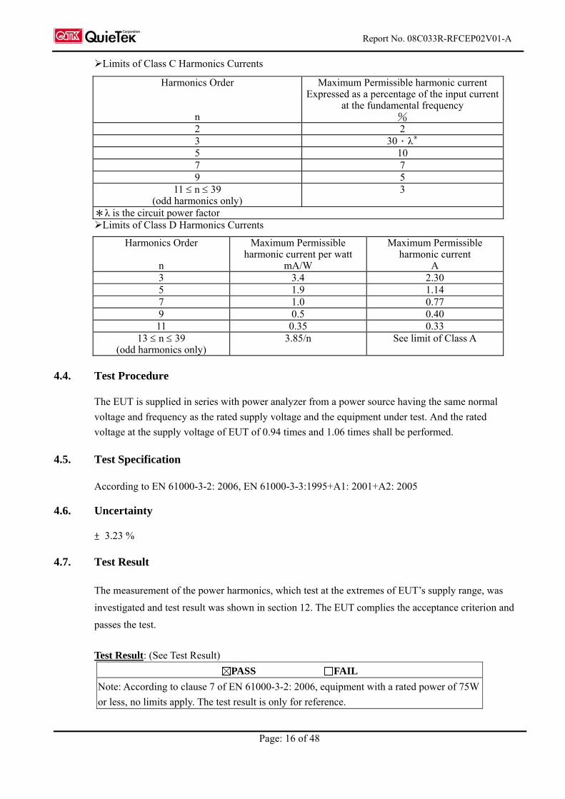
Limits of Class C Harmonics Currents
Harmonics Order
n
Maximum Permissible harmonic current Expressed as a percentage of the input current
at the fundamental frequency %
2 2 3 30.λ* 5 10 7 7 9 5
11 n 39 (odd harmonics only)
3
*λ is the circuit power factor Limits of Class D Harmonics Currents
Harmonics Order
n
Maximum Permissible harmonic current per watt
mA/W
Maximum Permissible harmonic current
A 3 3.4 2.30 5 1.9 1.14 7 1.0 0.77 9 0.5 0.40 11 0.35 0.33
13 n 39 (odd harmonics only)
3.85/n See limit of Class A
4.4. Test Procedure
The EUT is supplied in series with power analyzer from a power source having the same normal
voltage and frequency as the rated supply voltage and the equipment under test. And the rated
voltage at the supply voltage of EUT of 0.94 times and 1.06 times shall be performed.
4.5. Test Specification
According to EN 61000-3-2: 2006, EN 61000-3-3:1995+A1: 2001+A2: 2005
4.6. Uncertainty
± 3.23 %
4.7. Test Result
The measurement of the power harmonics, which test at the extremes of EUT’s supply range, was
investigated and test result was shown in section 12. The EUT complies the acceptance criterion and
passes the test.
Test Result: (See Test Result)
PASS FAIL
Note: According to clause 7 of EN 61000-3-2: 2006, equipment with a rated power of 75W
or less, no limits apply. The test result is only for reference.
Report No. 08C033R-RFCEP02V01-A
Page: 17 of 48
5. Electrostatic Discharge (ESD)
5.1. Test Equipment
Item Instrument Manufacturer Type No/Serial No. Last Calibration
1 ESD Simulator System SCHAFFNER NSG-438 S/N: 167 June, 2008
2 Horizontal Coupling Plane (HCP)
QuieTek HCP AL50 N/A
3 Vertical Coupling Plane (VCP)
QuieTek VCP AL50 N/A
4 No.3 Shielded Room
Note: All equipments are calibrated every one year.
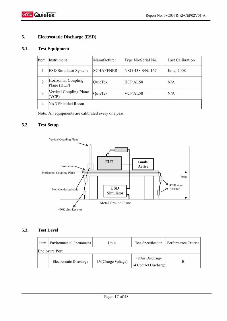
5.2. Test Setup
5.3. Test Level
Item Environmental Phenomena Units Test Specification Performance Criteria
Enclosure Port
Electrostatic Discharge kV(Charge Voltage) ±8 Air Discharge
±4 Contact Discharge B
Metal Ground Plane
ESD Simulator
EUT Loads: Active Insulation
Horizontal Coupling Plane
Non-Conducted table 470K ohm Resistor
470K ohm Resistor
Vertical Coupling Plane
80cm
Report No. 08C033R-RFCEP02V01-A
Page: 18 of 48
5.4. Test Procedure
Direct application of discharges to the EUT:
Contact discharge was applied only to conductive surfaces of the EUT.
Air discharges were applied only to non-conductive surfaces of the EUT.
During the test, it was performed with single discharges. For the single discharge time
between successive single discharges will be keep longer 1 second. It was at least ten single
discharges with positive and negative at the same selected point.
The selected point, which was performed with electrostatic discharge, was marked on the
red label of the EUT.
Indirect application of discharges to the EUT:
Vertical Coupling Plane (VCP):
The coupling plane, of dimensions 0.5m x 0.5m, is placed parallel to, and positioned at a
distance 0.1m from, the EUT, with the Discharge Electrode touching the coupling plane.
The four faces of the EUT will be performed with electrostatic discharge. It was at least ten
single discharges with positive and negative at the same selected point.
Horizontal Coupling Plane (HCP):
The coupling plane is placed under to the EUT. The generator shall be positioned vertically
at a distance of 0.1m from the EUT, with the Discharge Electrode touching the coupling
plane.
The four faces of the EUT will be performed with electrostatic discharge. It was at least ten
single discharges with positive and negative at the same selected point.
5.5. Test Specification
According to EN 61000-4-2 Edition 1.2: 2001-04
5.6. Uncertainty
± 6.003 %
5.7. Test Result
The measurement of the electrostatic discharge was investigated and test result was shown in section
12. The EUT complies the acceptance criterion and passes the test.
Report No. 08C033R-RFCEP02V01-A
Page: 19 of 48
6. Radiated Susceptibility (RS)
6.1. Test Equipment
Item Equipment Manufacturer Model No. / Serial No. Last Cal.
1 Signal Generator R & S SMY02 / 825454/029 Oct., 2008
2 Power Amplifier A & R 100W10000M7 / A285000010
N/A
3 RF Power Amplifier OPHIRRF 5022F / 1075 N/A
4 Bilog Antenna Chase CBL6112B / 2452 Sep., 2008
5 Power Meter R & S NRVD / 100219 Jan., 2008
6 Directional Coupler A & R DC6180 / 22735 Jan., 2008
7 No.5 EMC Fully Chamber
Note: All equipments are calibrated every one year.
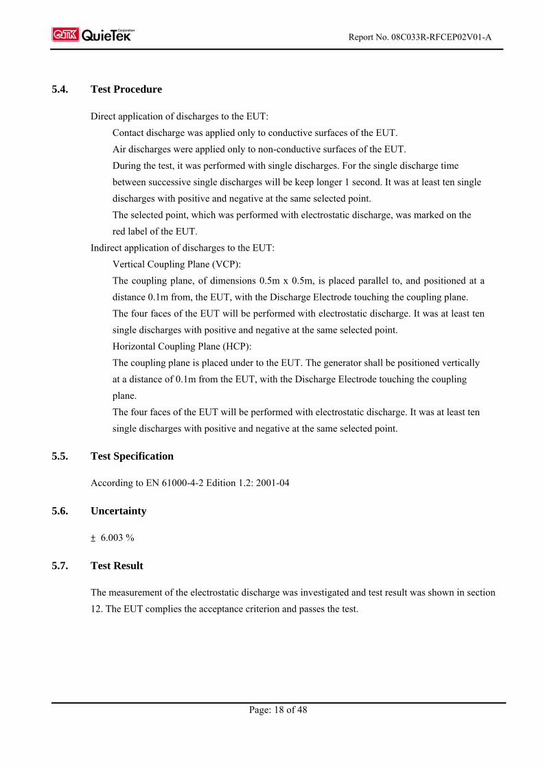
6.2. Test Setup
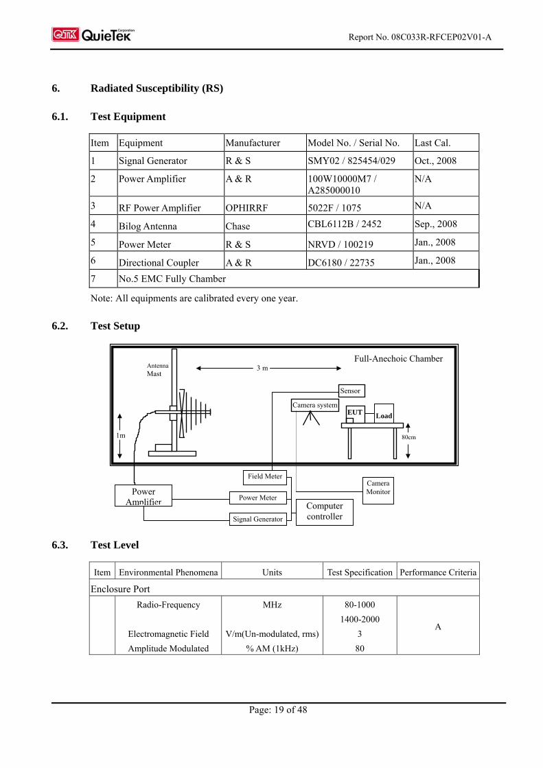
6.3. Test Level
Item Environmental Phenomena Units Test Specification Performance Criteria
Enclosure Port
Radio-Frequency
Electromagnetic Field
Amplitude Modulated
MHz
V/m(Un-modulated, rms)
% AM (1kHz)
80-1000
1400-2000
3
80
A
EUT
Sensor
80cm
3 m
1m
Full-Anechoic Chamber
Power Amplifier
Signal Generator
Field Meter
Computer controller
Camera system
Camera Monitor
Antenna Mast
Load
Power Meter
Report No. 08C033R-RFCEP02V01-A
Page: 20 of 48
6.4. Test Procedure
The EUT and load, which are placed on a table that is 0.8 meter above ground, are placed with
one coincident with the calibration plane such that the distance from antenna to the EUT was 3
meters.
Both horizontal and vertical polarization of the antenna and four sides of the EUT are set on
measurement.
In order to judge the EUT performance, a CCD camera is used to monitor EUT screen.
All the scanning conditions are as follows:
Condition of Test Remarks
1. Field Strength 3 V/m Level 2
2. Radiated Signal AM 80% Modulated with 1kHz sinusoidal audio signal
3. Scanning Frequency 80MHz - 1000MHz, 1400MHz - 2000MHz
4 Dwell Time 3 Seconds
5. Frequency step size f : 1%
6. The rate of Swept of Frequency 1.5 x 10⁻³ decades/s
6.5. Test Specification
According to EN 61000-4-3 Edition 3.0: 2006
6.6. Uncertainty
± 6.17 %
6.7. Test Result
The measurement of the radiated susceptibility was investigated and test result was shown in section
12. The EUT complies the acceptance criterion and passes the test.
Report No. 08C033R-RFCEP02V01-A
Page: 21 of 48
7. Electrical Fast Transient/Burst (EFT/B)
7.1. Test Equipment
Item Instrument Manufacturer Type No/Serial No. Last Calibration
1 Fast Transient/Burst
Generator
SCHAFFNER NSG 2050
S/N: 200124-031AR
June, 2008
2 No.2 Shielded Room
Note: All equipments are calibrated every one year.
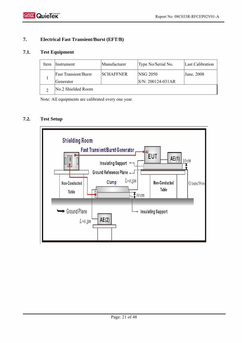
7.2. Test Setup
Report No. 08C033R-RFCEP02V01-A
Page: 22 of 48
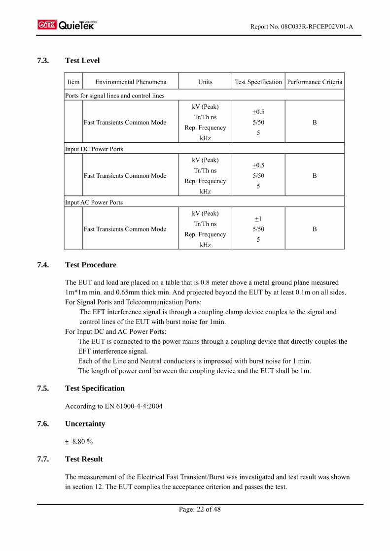
7.3. Test Level
Item Environmental Phenomena Units Test Specification Performance Criteria
Ports for signal lines and control lines
Fast Transients Common Mode
kV (Peak)
Tr/Th ns
Rep. Frequency
kHz
+0.5
5/50
5
B
Input DC Power Ports
Fast Transients Common Mode
kV (Peak)
Tr/Th ns
Rep. Frequency
kHz
+0.5
5/50
5
B
Input AC Power Ports
Fast Transients Common Mode
kV (Peak)
Tr/Th ns
Rep. Frequency
kHz
+1
5/50
5
B
7.4. Test Procedure
The EUT and load are placed on a table that is 0.8 meter above a metal ground plane measured 1m*1m min. and 0.65mm thick min. And projected beyond the EUT by at least 0.1m on all sides. For Signal Ports and Telecommunication Ports:
The EFT interference signal is through a coupling clamp device couples to the signal and control lines of the EUT with burst noise for 1min.
For Input DC and AC Power Ports: The EUT is connected to the power mains through a coupling device that directly couples the EFT interference signal. Each of the Line and Neutral conductors is impressed with burst noise for 1 min. The length of power cord between the coupling device and the EUT shall be 1m.
7.5. Test Specification
According to EN 61000-4-4:2004
7.6. Uncertainty
± 8.80 %
7.7. Test Result
The measurement of the Electrical Fast Transient/Burst was investigated and test result was shown in section 12. The EUT complies the acceptance criterion and passes the test.
Report No. 08C033R-RFCEP02V01-A
Page: 23 of 48
8. Surge
8.1. Test Equipment
Item Instrument Manufacturer Type No/Serial No. Last Calibration
1 Surge Generator SCHAFFNER NSG 2050
S/N: 200124-031AR
June, 2008
2 No.6 Shielded Room
Note: All equipments are calibrated every one year.
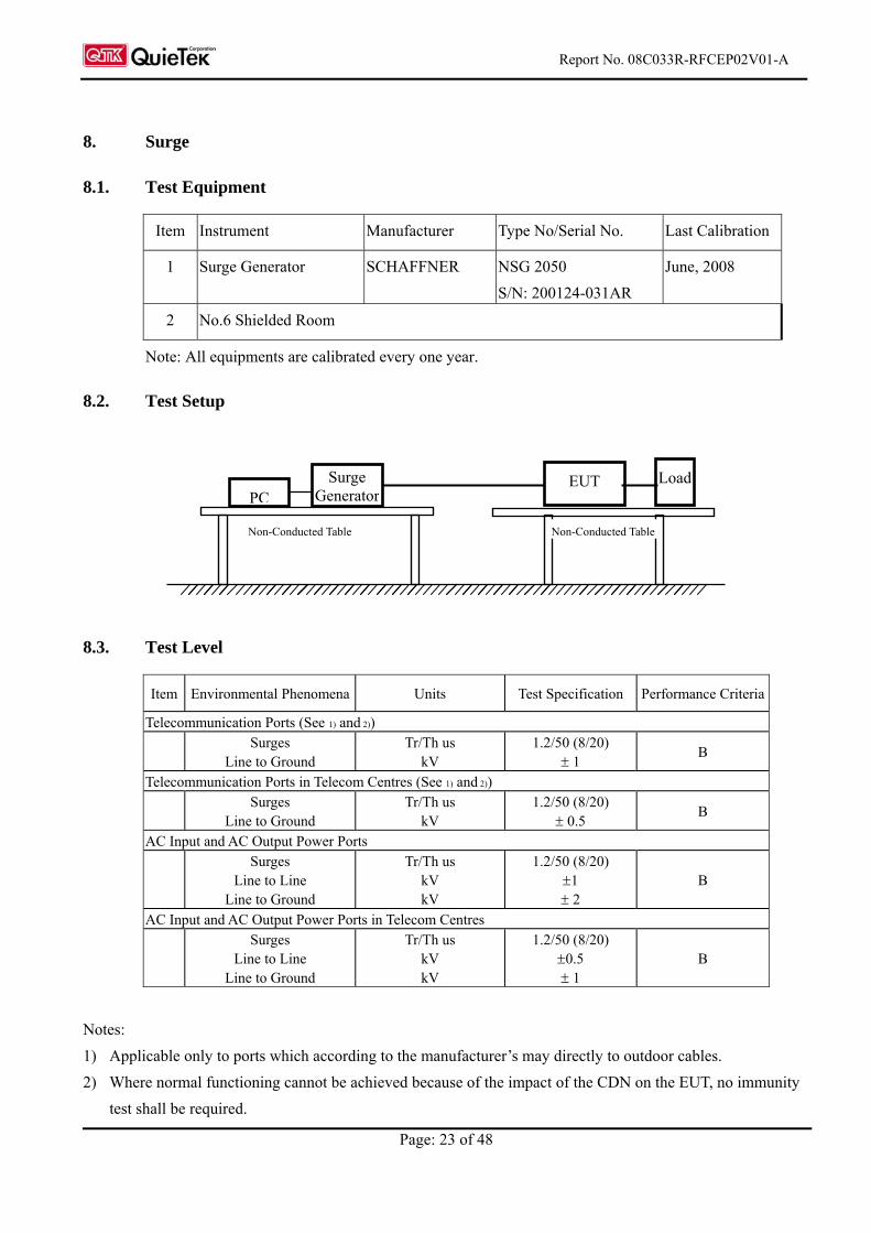
8.2. Test Setup
8.3. Test Level
Item Environmental Phenomena Units Test Specification Performance Criteria
Telecommunication Ports (See 1) and 2))
Surges
Line to Ground Tr/Th us
kV 1.2/50 (8/20)
1 B
Telecommunication Ports in Telecom Centres (See 1) and 2))
Surges
Line to Ground Tr/Th us
kV 1.2/50 (8/20)
0.5 B
AC Input and AC Output Power Ports
Surges
Line to Line Line to Ground
Tr/Th us kV kV
1.2/50 (8/20) 1 2
B
AC Input and AC Output Power Ports in Telecom Centres
Surges
Line to Line Line to Ground
Tr/Th us kV kV
1.2/50 (8/20) 0.5 1
B
Notes:
1) Applicable only to ports which according to the manufacturer’s may directly to outdoor cables.
2) Where normal functioning cannot be achieved because of the impact of the CDN on the EUT, no immunity
test shall be required.
Surge Generator
EUT Load PC
Non-Conducted Table Non-Conducted Table
Report No. 08C033R-RFCEP02V01-A
Page: 24 of 48
8.4. Test Procedure
The EUT and its load are placed on a table that is 0.8 meter above a metal ground plane measured
1m*1m min. and 0.65mm thick min. And projected beyond the EUT by at least 0.1m on all sides. The
length of power cord between the coupling device and the EUT shall be 2m or less.
For Signal Ports and Telecommunication Ports
The disturbance signal is through a coupling and decoupling networks (CDN) device couples to
the signal and Telecommunication lines of the EUT.
For Input and Output AC Power or DC Input and DC Output Power Ports:
The EUT is connected to the power mains through a coupling device that directly couples the
Surge interference signal.
The surge noise shall be applied synchronized to the voltage phase at 00, 900, 1800, 2700 and the
peak value of the a.c. voltage wave. (Positive and negative)
Each of Line-Earth and Line-Line is impressed with a sequence of five surge voltages with
interval of 1 min.
8.5. Test Specification
According to EN 61000-4-5 Edition 2.0: 2005
8.6. Uncertainty
± 7.93 %
8.7. Test Result
The measurement of the Surge was investigated and test result was shown in section 12. The EUT
complies the acceptance criterion and passes the test.
Report No. 08C033R-RFCEP02V01-A
Page: 25 of 48
9. Conducted Susceptibility (CS)
9.1. Test Equipment
Item Equipment Manufacturer Model No. / Serial No. Last Cal.
1 CS SYSTEM SCHAFFNER NSG 2070 March, 2008
2 CDN SCHAFFNER CDN M016S / 20822 Dec., 2008
3 CDN SCHAFFNER CDN M016S / 20823 Dec., 2008
4 FIXED PAD SCHAFFNER INA 2070-1 / 2115 N/A
5 EM Clamp N/A KEMZ 801 / 21024 March, 2008
6 No.6 Shielded Room
Note: All equipments are calibrated every one year.
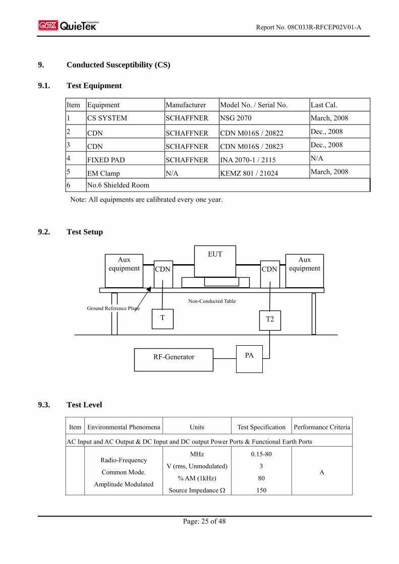
9.2. Test Setup
9.3. Test Level
Item Environmental Phenomena Units Test Specification Performance Criteria
AC Input and AC Output & DC Input and DC output Power Ports & Functional Earth Ports
Radio-Frequency
Common Mode.
Amplitude Modulated
MHz
V (rms, Unmodulated)
% AM (1kHz)
Source Impedance
0.15-80
3
80
150
A
Aux equipment
EUT
CDN
RF-Generator
T2
Ground Reference Plane Non-Conducted Table
CDNAux
equipment
T
PA
Report No. 08C033R-RFCEP02V01-A
Page: 26 of 48
9.4. Test Procedure
The EUT are placed on a table that is 0.8 meter height, and a Ground reference plane on the table,
EUT are placed upon table and use a 10cm insulation between the EUT and Ground reference
plane.
For Signal Ports and Telecommunication Ports
The disturbance signal is through a coupling and decoupling networks (CDN) or EM-clamp
device couples to the signal and Telecommunication lines of the EUT.
For Input DC and AC Power Ports
The EUT is connected to the power mains through a coupling and decoupling networks for power
supply lines. And directly couples the disturbances signal into EUT.
Used CDN-M2 for two wires or CDN-M3 for three wires.
All the scanning conditions are as follows:
Condition of Test Remarks
1. Field Strength 130dBuV(3V) Level 2
2. Radiated Signal AM 80% Modulated with 1kHz sinusoidal audio signal
3. Scanning Frequency 0.15MHz – 80MHz
4 Dwell Time 3 Seconds
5. Frequency step size f : 1%
6. The rate of Swept of Frequency 1.5 x 10⁻³ decades/s
9.5. Test Specification
According to EN 61000-4-6 Edition 2.2: 2006
9.6. Uncertainty
± 6.17 %
9.7. Test Result
The measurement of the Conducted Susceptibility was investigated and test result was shown in
section 12. The EUT complies the acceptance criterion and passes the test.
Report No. 08C033R-RFCEP02V01-A
Page: 27 of 48
10. Voltage Dips and Interruption
10.1. Test Equipment
Item Instrument Manufacturer Type No/Serial No. Last Calibration
1 Voltage Dips Generator SCHAFFNER NSG 2050
S/N: 200124-031AR
June, 2008
2 No.6 Shielded Room
Note: All equipments are calibrated every one year.
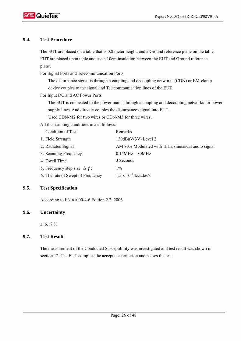
10.2. Test Setup
10.3. Test Level
Item Environmental Phenomena Units Test Specification Performance Criteria
AC Input and AC Output Power Ports
Voltage Dips % Reduction
ms
30
10 B
Voltage Dips % Reduction
ms
60
100 C
Voltage Interruptions % Reduction
ms
> 95 %
5000 C
Voltage Dips/ Interruptions /Variations Simulator
EUT Load To AC Line
Controller Computer Printer
Non-Conducted Table 80cm
AC Power Line to EUT
Report No. 08C033R-RFCEP02V01-A
Page: 28 of 48
10.4. Test Procedure
The EUT and its load are placed on a table which is 0.8 meter above a metal ground plane
measured 1m*1m min. and 0.65mm thick min. And projected beyond the EUT by at least 0.1m
on all sides. The power cord shall be used the shortest power cord as specified by the
manufacturer.
For Voltage Dips/ Interruptions test:
The selection of test voltage is based on the rated power range. If the operation range is large
than 20% of lower power range, both end of specified voltage shall be tested. Otherwise, the
typical voltage specification is selected as test voltage.
The EUT is connected to the power mains through a coupling device that directly couples to
the Voltage Dips and Interruption Generator.
The EUT shall be tested for 30% voltage dip of supplied voltage and duration 10ms, with a
sequence of three voltage dips with intervals of 10 seconds, for 60% voltage dip of supplied
voltage and duration 100ms with a sequence of three voltage dips with intervals of 10
seconds, and for 95% voltage interruption of supplied voltage and duration 5000ms with a
sequence of three voltage interruptions with intervals of 10 seconds.
Voltage phase shifting are shall occur at 00, 450, 900 ,1350 ,1800 ,2250, 2700 ,3150 of the
voltage.
10.5. Test Specification
According to EN 61000-4-11:2004
10.6. Uncertainty
± 2.03 %
10.7. Test Result
The measurement of the Voltage Dips and Interruption was investigated and test result was shown in
section 12. The EUT complies the acceptance criterion and passes the test.
Report No. 08C033R-RFCEP02V01-A
Page: 29 of 48
11. EMC Reduction Method During Compliance Testing
No modification was made during testing.
Report No. 08C033R-RFCEP02V01-A
Page: 30 of 48
12. Test Result
The test results in the emission and the immunity were performed according to the requirements of
measurement standard and process. Quietek Corporation is assumed full responsibility for the
accuracy and completeness of these measurements. The test data of the emission is listed as below.
All the tests were carried out with the EUT in normal operation, which was defined as:
EMI Mode Mode 1: Normal Operation (AR5BXB63)
EMS Mode Mode 1: Normal Operation (AR5BXB63)
Report No. 08C033R-RFCEP02V01-A
Page: 31 of 48
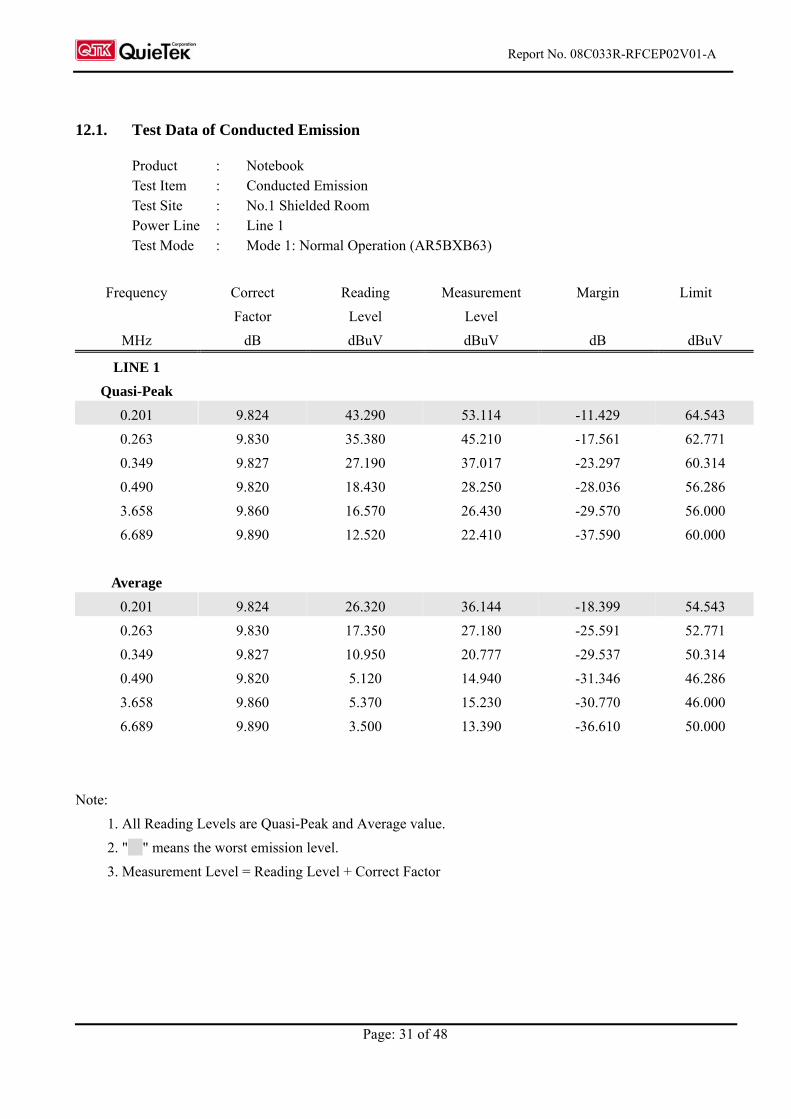
12.1. Test Data of Conducted Emission
Product : Notebook Test Item : Conducted Emission Test Site : No.1 Shielded Room Power Line : Line 1 Test Mode : Mode 1: Normal Operation (AR5BXB63)
Frequency Correct Reading Measurement Margin Limit
Factor Level Level
MHz dB dBuV dBuV dB dBuV
LINE 1
Quasi-Peak
0.201 9.824 43.290 53.114 -11.429 64.543
0.263 9.830 35.380 45.210 -17.561 62.771
0.349 9.827 27.190 37.017 -23.297 60.314
0.490 9.820 18.430 28.250 -28.036 56.286
3.658 9.860 16.570 26.430 -29.570 56.000
6.689 9.890 12.520 22.410 -37.590 60.000
Average
0.201 9.824 26.320 36.144 -18.399 54.543
0.263 9.830 17.350 27.180 -25.591 52.771
0.349 9.827 10.950 20.777 -29.537 50.314
0.490 9.820 5.120 14.940 -31.346 46.286
3.658 9.860 5.370 15.230 -30.770 46.000
6.689 9.890 3.500 13.390 -36.610 50.000
Note:
1. All Reading Levels are Quasi-Peak and Average value.
2. " " means the worst emission level.
3. Measurement Level = Reading Level + Correct Factor
Report No. 08C033R-RFCEP02V01-A
Page: 32 of 48
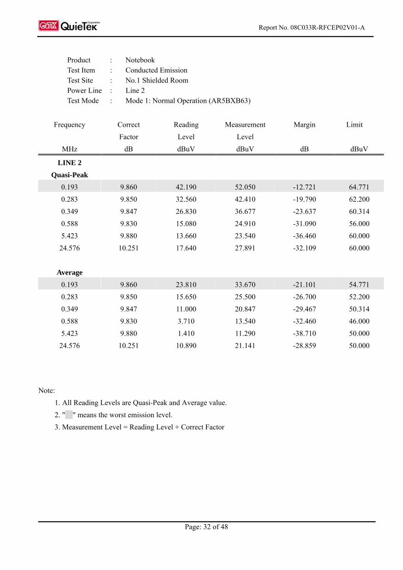
Product : Notebook Test Item : Conducted Emission Test Site : No.1 Shielded Room Power Line : Line 2 Test Mode : Mode 1: Normal Operation (AR5BXB63)
Frequency Correct Reading Measurement Margin Limit
Factor Level Level
MHz dB dBuV dBuV dB dBuV
LINE 2
Quasi-Peak
0.193 9.860 42.190 52.050 -12.721 64.771
0.283 9.850 32.560 42.410 -19.790 62.200
0.349 9.847 26.830 36.677 -23.637 60.314
0.588 9.830 15.080 24.910 -31.090 56.000
5.423 9.880 13.660 23.540 -36.460 60.000
24.576 10.251 17.640 27.891 -32.109 60.000
Average
0.193 9.860 23.810 33.670 -21.101 54.771
0.283 9.850 15.650 25.500 -26.700 52.200
0.349 9.847 11.000 20.847 -29.467 50.314
0.588 9.830 3.710 13.540 -32.460 46.000
5.423 9.880 1.410 11.290 -38.710 50.000
24.576 10.251 10.890 21.141 -28.859 50.000
Note:
1. All Reading Levels are Quasi-Peak and Average value.
2. " " means the worst emission level.
3. Measurement Level = Reading Level + Correct Factor
Report No. 08C033R-RFCEP02V01-A
Page: 33 of 48
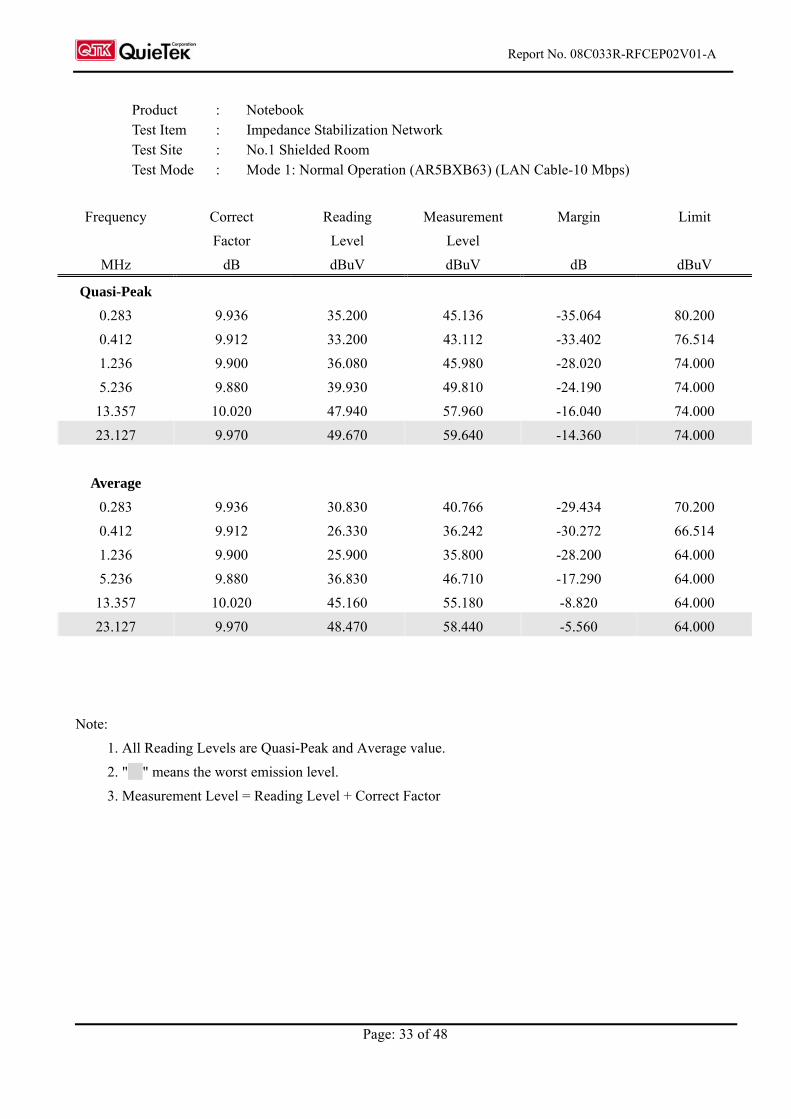
Frequency Correct Reading Measurement Margin Limit
Factor Level Level
MHz dB dBuV dBuV dB dBuV
Quasi-Peak
0.283 9.936 35.200 45.136 -35.064 80.200
0.412 9.912 33.200 43.112 -33.402 76.514
1.236 9.900 36.080 45.980 -28.020 74.000
5.236 9.880 39.930 49.810 -24.190 74.000
13.357 10.020 47.940 57.960 -16.040 74.000
23.127 9.970 49.670 59.640 -14.360 74.000
Average
0.283 9.936 30.830 40.766 -29.434 70.200
0.412 9.912 26.330 36.242 -30.272 66.514
1.236 9.900 25.900 35.800 -28.200 64.000
5.236 9.880 36.830 46.710 -17.290 64.000
13.357 10.020 45.160 55.180 -8.820 64.000
23.127 9.970 48.470 58.440 -5.560 64.000
Note:
1. All Reading Levels are Quasi-Peak and Average value.
2. " " means the worst emission level.
3. Measurement Level = Reading Level + Correct Factor
Product : Notebook Test Item : Impedance Stabilization Network Test Site : No.1 Shielded Room Test Mode : Mode 1: Normal Operation (AR5BXB63) (LAN Cable-10 Mbps)
Report No. 08C033R-RFCEP02V01-A
Page: 34 of 48
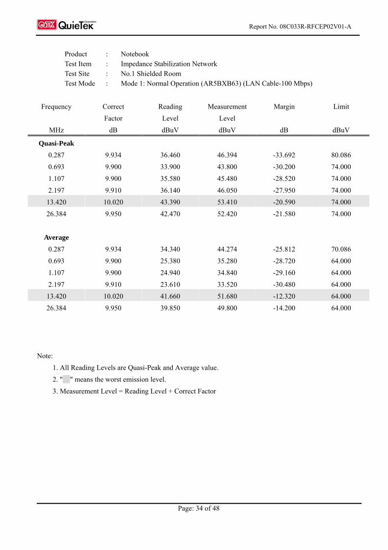
Frequency Correct Reading Measurement Margin Limit
Factor Level Level
MHz dB dBuV dBuV dB dBuV
Quasi-Peak
0.287 9.934 36.460 46.394 -33.692 80.086
0.693 9.900 33.900 43.800 -30.200 74.000
1.107 9.900 35.580 45.480 -28.520 74.000
2.197 9.910 36.140 46.050 -27.950 74.000
13.420 10.020 43.390 53.410 -20.590 74.000
26.384 9.950 42.470 52.420 -21.580 74.000
Average
0.287 9.934 34.340 44.274 -25.812 70.086
0.693 9.900 25.380 35.280 -28.720 64.000
1.107 9.900 24.940 34.840 -29.160 64.000
2.197 9.910 23.610 33.520 -30.480 64.000
13.420 10.020 41.660 51.680 -12.320 64.000
26.384 9.950 39.850 49.800 -14.200 64.000
Note:
1. All Reading Levels are Quasi-Peak and Average value.
2. " " means the worst emission level.
3. Measurement Level = Reading Level + Correct Factor
Product : Notebook Test Item : Impedance Stabilization Network Test Site : No.1 Shielded Room Test Mode : Mode 1: Normal Operation (AR5BXB63) (LAN Cable-100 Mbps)
Report No. 08C033R-RFCEP02V01-A
Page: 35 of 48
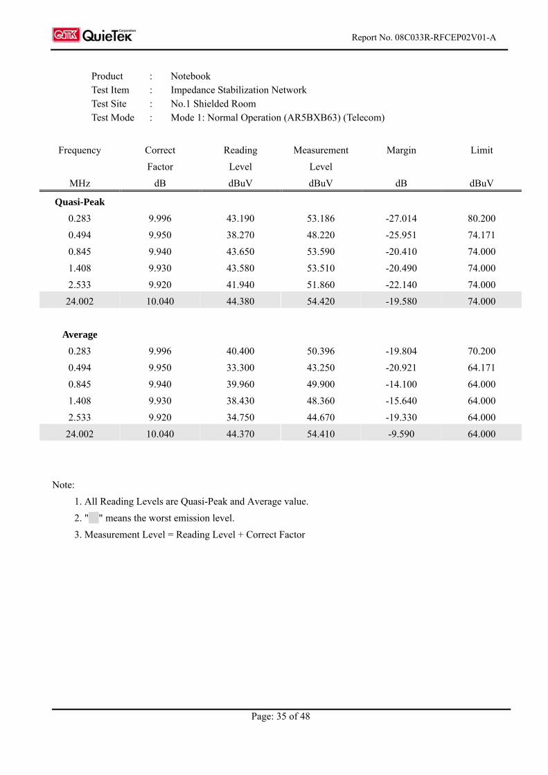
Product : Notebook Test Item : Impedance Stabilization Network Test Site : No.1 Shielded Room Test Mode : Mode 1: Normal Operation (AR5BXB63) (Telecom)
Frequency Correct Reading Measurement Margin Limit
Factor Level Level
MHz dB dBuV dBuV dB dBuV
Quasi-Peak
0.283 9.996 43.190 53.186 -27.014 80.200
0.494 9.950 38.270 48.220 -25.951 74.171
0.845 9.940 43.650 53.590 -20.410 74.000
1.408 9.930 43.580 53.510 -20.490 74.000
2.533 9.920 41.940 51.860 -22.140 74.000
24.002 10.040 44.380 54.420 -19.580 74.000
Average
0.283 9.996 40.400 50.396 -19.804 70.200
0.494 9.950 33.300 43.250 -20.921 64.171
0.845 9.940 39.960 49.900 -14.100 64.000
1.408 9.930 38.430 48.360 -15.640 64.000
2.533 9.920 34.750 44.670 -19.330 64.000
24.002 10.040 44.370 54.410 -9.590 64.000
Note:
1. All Reading Levels are Quasi-Peak and Average value.
2. " " means the worst emission level.
3. Measurement Level = Reading Level + Correct Factor
Report No. 08C033R-RFCEP02V01-A
Page: 36 of 48
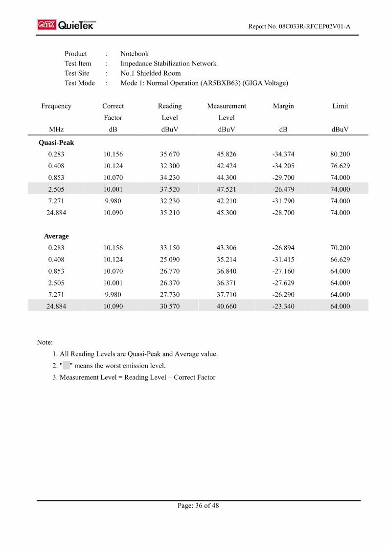
Product : Notebook Test Item : Impedance Stabilization Network Test Site : No.1 Shielded Room Test Mode : Mode 1: Normal Operation (AR5BXB63) (GIGA Voltage)
Frequency Correct Reading Measurement Margin Limit
Factor Level Level
MHz dB dBuV dBuV dB dBuV
Quasi-Peak
0.283 10.156 35.670 45.826 -34.374 80.200
0.408 10.124 32.300 42.424 -34.205 76.629
0.853 10.070 34.230 44.300 -29.700 74.000
2.505 10.001 37.520 47.521 -26.479 74.000
7.271 9.980 32.230 42.210 -31.790 74.000
24.884 10.090 35.210 45.300 -28.700 74.000
Average
0.283 10.156 33.150 43.306 -26.894 70.200
0.408 10.124 25.090 35.214 -31.415 66.629
0.853 10.070 26.770 36.840 -27.160 64.000
2.505 10.001 26.370 36.371 -27.629 64.000
7.271 9.980 27.730 37.710 -26.290 64.000
24.884 10.090 30.570 40.660 -23.340 64.000
Note:
1. All Reading Levels are Quasi-Peak and Average value.
2. " " means the worst emission level.
3. Measurement Level = Reading Level + Correct Factor
Report No. 08C033R-RFCEP02V01-A
Page: 37 of 48
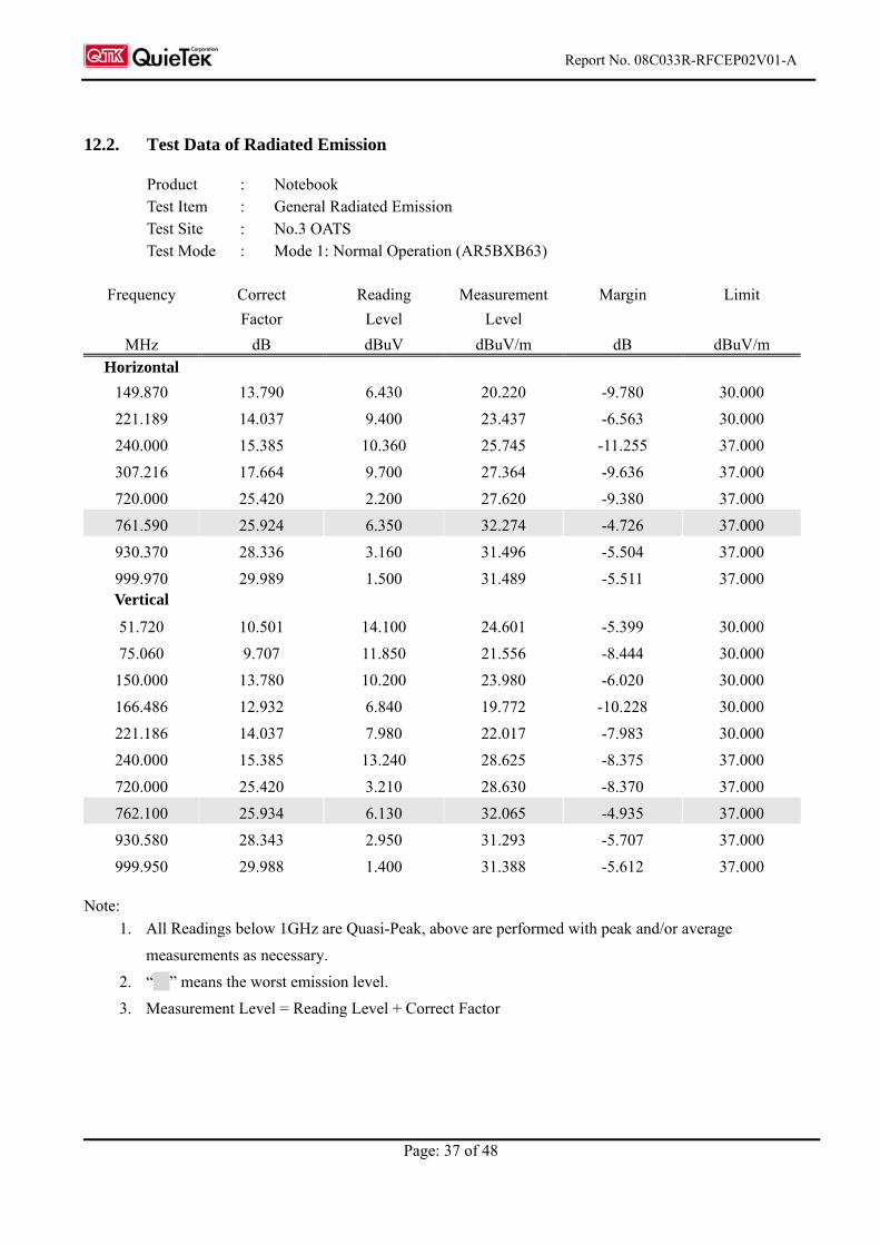
12.2. Test Data of Radiated Emission
Product : Notebook Test Item : General Radiated Emission Test Site : No.3 OATS Test Mode : Mode 1: Normal Operation (AR5BXB63)
Frequency Correct Reading Measurement Margin Limit
Factor Level Level
MHz dB dBuV dBuV/m dB dBuV/m
Horizontal
149.870 13.790 6.430 20.220 -9.780 30.000
221.189 14.037 9.400 23.437 -6.563 30.000
240.000 15.385 10.360 25.745 -11.255 37.000
307.216 17.664 9.700 27.364 -9.636 37.000
720.000 25.420 2.200 27.620 -9.380 37.000
761.590 25.924 6.350 32.274 -4.726 37.000
930.370 28.336 3.160 31.496 -5.504 37.000
999.970 29.989 1.500 31.489 -5.511 37.000 Vertical
51.720 10.501 14.100 24.601 -5.399 30.000
75.060 9.707 11.850 21.556 -8.444 30.000
150.000 13.780 10.200 23.980 -6.020 30.000
166.486 12.932 6.840 19.772 -10.228 30.000
221.186 14.037 7.980 22.017 -7.983 30.000
240.000 15.385 13.240 28.625 -8.375 37.000
720.000 25.420 3.210 28.630 -8.370 37.000
762.100 25.934 6.130 32.065 -4.935 37.000
930.580 28.343 2.950 31.293 -5.707 37.000
999.950 29.988 1.400 31.388 -5.612 37.000 Note:
1. All Readings below 1GHz are Quasi-Peak, above are performed with peak and/or average
measurements as necessary.
2. “ ” means the worst emission level.
3. Measurement Level = Reading Level + Correct Factor
Report No. 08C033R-RFCEP02V01-A
Page: 38 of 48
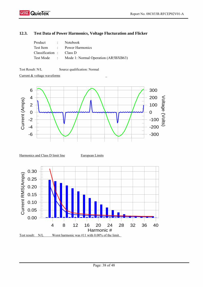
12.3. Test Data of Power Harmonics, Voltage Flucturation and Flicker
Product : Notebook Test Item : Power Harmonics Classification : Class D Test Mode : Mode 1: Normal Operation (AR5BXB63)
Test Result: N/L Source qualification: Normal
Current & voltage waveforms
-6
-4
-2
0
2
4
6
-300
-200
-100
0
100
200
300
Cu
rre
nt (A
mp
s)
Vo
ltag
e (V
olts)
Harmonics and Class D limit line European Limits
0.00
0.05
0.10
0.15
0.20
0.25
0.30
Cu
rre
nt R
MS
(Am
ps)
Harmonic #4 8 12 16 20 24 28 32 36 40
Test result: N/L Worst harmonic was #11 with 0.00% of the limit.
Report No. 08C033R-RFCEP02V01-A
Page: 39 of 48
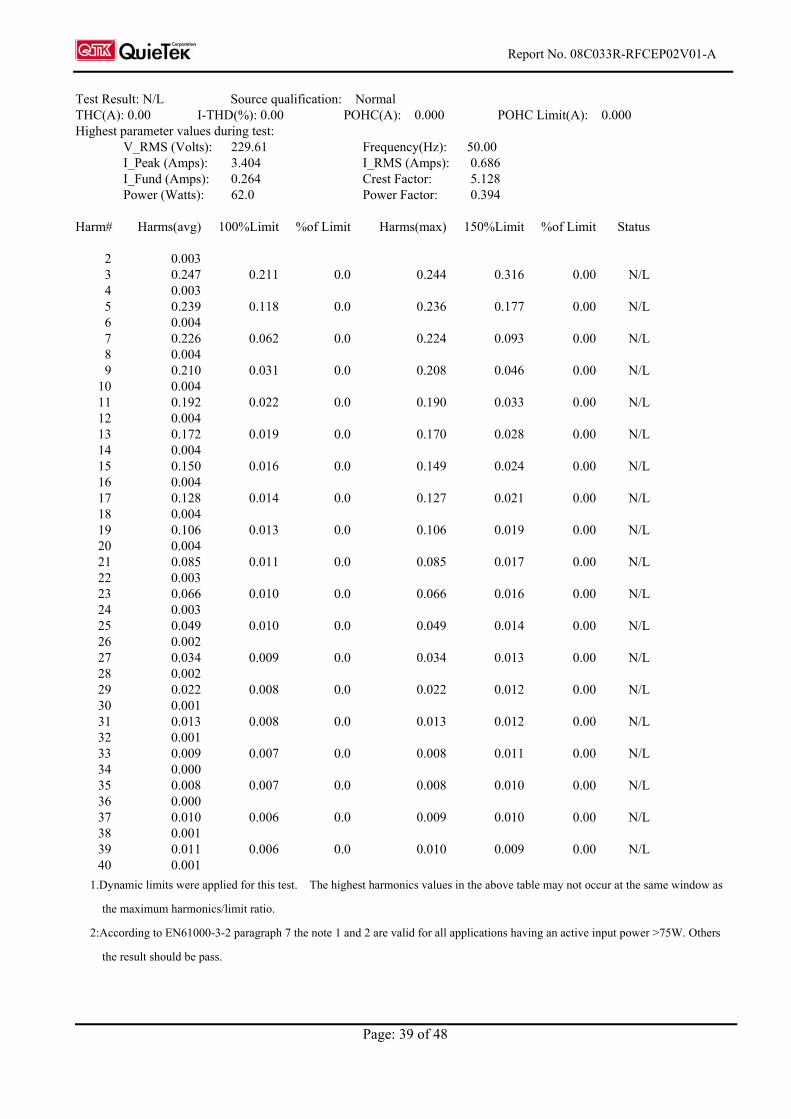
Test Result: N/L Source qualification: Normal THC(A): 0.00 I-THD(%): 0.00 POHC(A): 0.000 POHC Limit(A): 0.000 Highest parameter values during test:
V_RMS (Volts): 229.61 Frequency(Hz): 50.00 I_Peak (Amps): 3.404 I_RMS (Amps): 0.686 I_Fund (Amps): 0.264 Crest Factor: 5.128 Power (Watts): 62.0 Power Factor: 0.394
Harm# Harms(avg) 100%Limit %of Limit Harms(max) 150%Limit %of Limit Status 2 0.003 3 0.247 0.211 0.0 0.244 0.316 0.00 N/L 4 0.003 5 0.239 0.118 0.0 0.236 0.177 0.00 N/L 6 0.004 7 0.226 0.062 0.0 0.224 0.093 0.00 N/L 8 0.004 9 0.210 0.031 0.0 0.208 0.046 0.00 N/L 10 0.004 11 0.192 0.022 0.0 0.190 0.033 0.00 N/L 12 0.004 13 0.172 0.019 0.0 0.170 0.028 0.00 N/L 14 0.004 15 0.150 0.016 0.0 0.149 0.024 0.00 N/L 16 0.004 17 0.128 0.014 0.0 0.127 0.021 0.00 N/L 18 0.004 19 0.106 0.013 0.0 0.106 0.019 0.00 N/L 20 0.004 21 0.085 0.011 0.0 0.085 0.017 0.00 N/L 22 0.003 23 0.066 0.010 0.0 0.066 0.016 0.00 N/L 24 0.003 25 0.049 0.010 0.0 0.049 0.014 0.00 N/L 26 0.002 27 0.034 0.009 0.0 0.034 0.013 0.00 N/L 28 0.002 29 0.022 0.008 0.0 0.022 0.012 0.00 N/L 30 0.001 31 0.013 0.008 0.0 0.013 0.012 0.00 N/L 32 0.001 33 0.009 0.007 0.0 0.008 0.011 0.00 N/L 34 0.000 35 0.008 0.007 0.0 0.008 0.010 0.00 N/L 36 0.000 37 0.010 0.006 0.0 0.009 0.010 0.00 N/L 38 0.001 39 0.011 0.006 0.0 0.010 0.009 0.00 N/L 40 0.001
1.Dynamic limits were applied for this test. The highest harmonics values in the above table may not occur at the same window as
the maximum harmonics/limit ratio.
2:According to EN61000-3-2 paragraph 7 the note 1 and 2 are valid for all applications having an active input power >75W. Others
the result should be pass.
Report No. 08C033R-RFCEP02V01-A
Page: 40 of 48
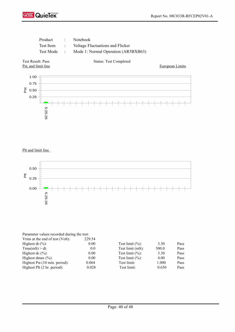
Product : Notebook Test Item : Voltage Fluctuations and Flicker Test Mode : Mode 1: Normal Operation (AR5BXB63)
Test Result: Pass Status: Test Completed Psti and limit line European Limits
0.25
0.50
0.75
1.00
Pst
5:2
5:2
6
Plt and limit line
0.00
0.25
0.50
Plt
5:2
5:2
6
Parameter values recorded during the test: Vrms at the end of test (Volt): 229.54 Highest dt (%): 0.00 Test limit (%): 3.30 Pass Time(mS) > dt: 0.0 Test limit (mS): 500.0 Pass Highest dc (%): 0.00 Test limit (%): 3.30 Pass Highest dmax (%): 0.00 Test limit (%): 4.00 Pass Highest Pst (10 min. period): 0.064 Test limit: 1.000 Pass Highest Plt (2 hr. period): 0.028 Test limit: 0.650 Pass
Report No. 08C033R-RFCEP02V01-A
Page: 41 of 48
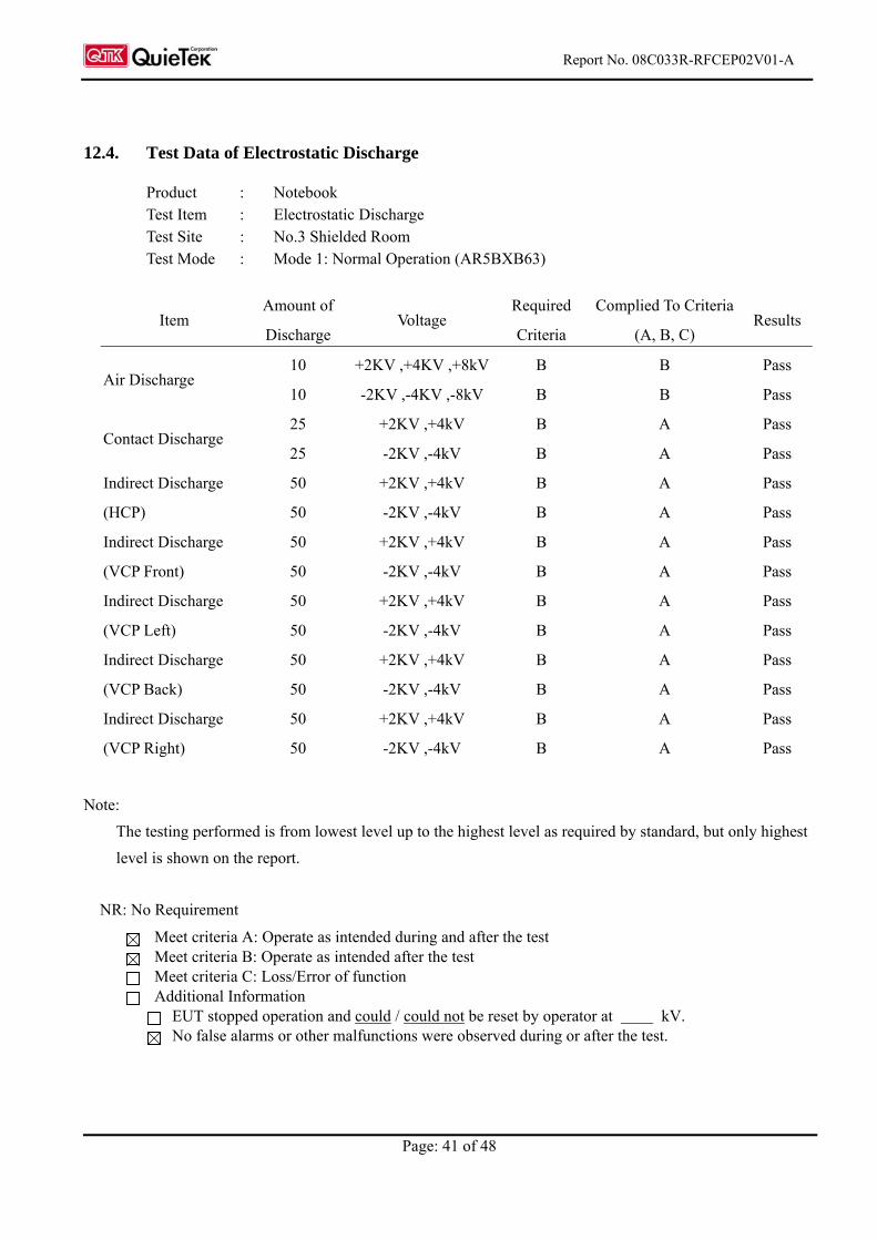
12.4. Test Data of Electrostatic Discharge
Product : Notebook Test Item : Electrostatic Discharge Test Site : No.3 Shielded Room Test Mode : Mode 1: Normal Operation (AR5BXB63)
Item Amount of
Discharge Voltage
Required
Criteria
Complied To Criteria
(A, B, C) Results
Air Discharge 10
10
+2KV ,+4KV ,+8kV
-2KV ,-4KV ,-8kV
B
B
B
B
Pass
Pass
Contact Discharge 25
25
+2KV ,+4kV
-2KV ,-4kV
B
B
A
A
Pass
Pass
Indirect Discharge
(HCP)
50
50
+2KV ,+4kV
-2KV ,-4kV
B
B
A
A
Pass
Pass
Indirect Discharge
(VCP Front)
50
50
+2KV ,+4kV
-2KV ,-4kV
B
B
A
A
Pass
Pass
Indirect Discharge
(VCP Left)
50
50
+2KV ,+4kV
-2KV ,-4kV
B
B
A
A
Pass
Pass
Indirect Discharge
(VCP Back)
50
50
+2KV ,+4kV
-2KV ,-4kV
B
B
A
A
Pass
Pass
Indirect Discharge
(VCP Right)
50
50
+2KV ,+4kV
-2KV ,-4kV
B
B
A
A
Pass
Pass
Note:
The testing performed is from lowest level up to the highest level as required by standard, but only highest
level is shown on the report.
NR: No Requirement
Meet criteria A: Operate as intended during and after the test Meet criteria B: Operate as intended after the test Meet criteria C: Loss/Error of function Additional Information
EUT stopped operation and could / could not be reset by operator at kV. No false alarms or other malfunctions were observed during or after the test.
Report No. 08C033R-RFCEP02V01-A
Page: 42 of 48
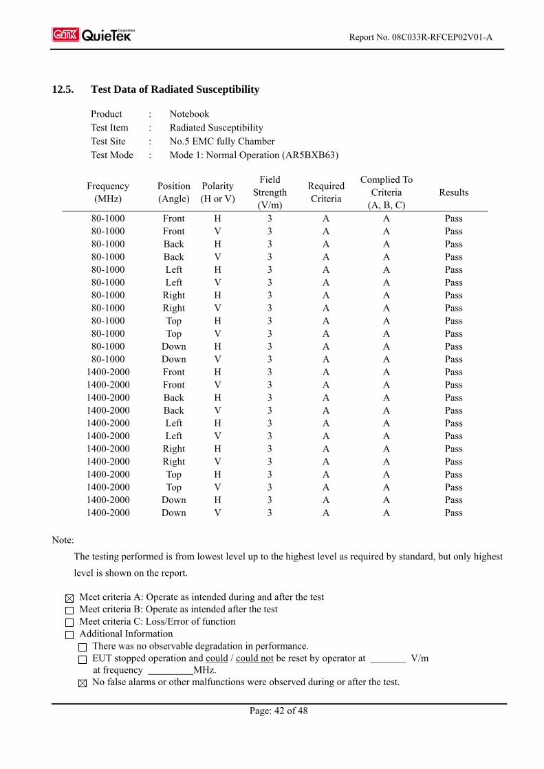
12.5. Test Data of Radiated Susceptibility
Product : Notebook Test Item : Radiated Susceptibility Test Site : No.5 EMC fully Chamber Test Mode : Mode 1: Normal Operation (AR5BXB63)
Frequency (MHz)
Position (Angle)
Polarity(H or V)
Field Strength (V/m)
Required Criteria
Complied To Criteria
(A, B, C) Results
80-1000 Front H 3 A A Pass 80-1000 Front V 3 A A Pass 80-1000 Back H 3 A A Pass 80-1000 Back V 3 A A Pass 80-1000 Left H 3 A A Pass 80-1000 Left V 3 A A Pass 80-1000 Right H 3 A A Pass 80-1000 Right V 3 A A Pass 80-1000 Top H 3 A A Pass 80-1000 Top V 3 A A Pass 80-1000 Down H 3 A A Pass 80-1000 Down V 3 A A Pass
1400-2000 Front H 3 A A Pass 1400-2000 Front V 3 A A Pass 1400-2000 Back H 3 A A Pass 1400-2000 Back V 3 A A Pass 1400-2000 Left H 3 A A Pass 1400-2000 Left V 3 A A Pass 1400-2000 Right H 3 A A Pass 1400-2000 Right V 3 A A Pass 1400-2000 Top H 3 A A Pass 1400-2000 Top V 3 A A Pass 1400-2000 Down H 3 A A Pass 1400-2000 Down V 3 A A Pass
Note:
The testing performed is from lowest level up to the highest level as required by standard, but only highest
level is shown on the report.
Meet criteria A: Operate as intended during and after the test Meet criteria B: Operate as intended after the test Meet criteria C: Loss/Error of function Additional Information
There was no observable degradation in performance. EUT stopped operation and could / could not be reset by operator at V/m
at frequency MHz. No false alarms or other malfunctions were observed during or after the test.
Report No. 08C033R-RFCEP02V01-A
Page: 43 of 48
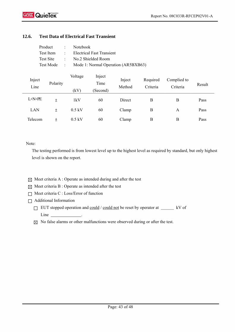
12.6. Test Data of Electrical Fast Transient
Product : Notebook Test Item : Electrical Fast Transient Test Site : No.2 Shielded Room Test Mode : Mode 1: Normal Operation (AR5BXB63)
Note:
The testing performed is from lowest level up to the highest level as required by standard, but only highest
level is shown on the report.
Meet criteria A : Operate as intended during and after the test
Meet criteria B : Operate as intended after the test
Meet criteria C : Loss/Error of function
Additional Information
EUT stopped operation and could / could not be reset by operator at kV of
Line .
No false alarms or other malfunctions were observed during or after the test.
Inject
Line Polarity
Voltage
(kV)
Inject
Time
(Second)
Inject
Method
Required
Criteria
Complied to
Criteria Result
L+N+PE ± 1kV 60 Direct B B Pass
LAN ± 0.5 kV 60 Clamp B A Pass
Telecom ± 0.5 kV 60 Clamp B B Pass
Report No. 08C033R-RFCEP02V01-A
Page: 44 of 48
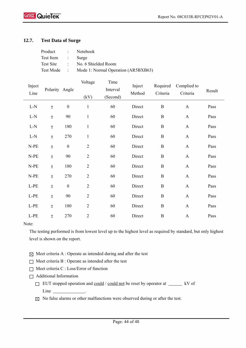
12.7. Test Data of Surge
Product : Notebook Test Item : Surge Test Site : No. 6 Shielded Room Test Mode : Mode 1: Normal Operation (AR5BXB63)
Inject
Line Polarity Angle
Voltage
(kV)
Time
Interval
(Second)
Inject
Method
Required
Criteria
Complied to
Criteria Result
L-N ± 0 1 60 Direct B A Pass
L-N ± 90 1 60 Direct B A Pass
L-N ± 180 1 60 Direct B A Pass
L-N ± 270 1 60 Direct B A Pass
N-PE ± 0 2 60 Direct B A Pass
N-PE ± 90 2 60 Direct B A Pass
N-PE ± 180 2 60 Direct B A Pass
N-PE ± 270 2 60 Direct B A Pass
L-PE ± 0 2 60 Direct B A Pass
L-PE ± 90 2 60 Direct B A Pass
L-PE ± 180 2 60 Direct B A Pass
L-PE ± 270 2 60 Direct B A Pass
Note:
The testing performed is from lowest level up to the highest level as required by standard, but only highest
level is shown on the report.
Meet criteria A : Operate as intended during and after the test
Meet criteria B : Operate as intended after the test
Meet criteria C : Loss/Error of function
Additional Information
EUT stopped operation and could / could not be reset by operator at kV of
Line .
No false alarms or other malfunctions were observed during or after the test.
Report No. 08C033R-RFCEP02V01-A
Page: 45 of 48
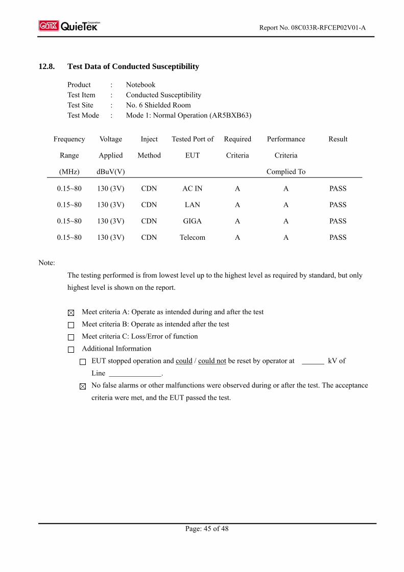
12.8. Test Data of Conducted Susceptibility
Product : Notebook Test Item : Conducted Susceptibility Test Site : No. 6 Shielded Room Test Mode : Mode 1: Normal Operation (AR5BXB63)
Frequency
Range
(MHz)
Voltage
Applied
dBuV(V)
Inject
Method
Tested Port of
EUT
Required
Criteria
Performance
Criteria
Complied To
Result
0.15~80 130 (3V) CDN AC IN A A PASS
0.15~80 130 (3V) CDN LAN A A PASS
0.15~80 130 (3V) CDN GIGA A A PASS
0.15~80 130 (3V) CDN Telecom A A PASS
Note:
The testing performed is from lowest level up to the highest level as required by standard, but only
highest level is shown on the report.
Meet criteria A: Operate as intended during and after the test
Meet criteria B: Operate as intended after the test
Meet criteria C: Loss/Error of function
Additional Information
EUT stopped operation and could / could not be reset by operator at kV of
Line .
No false alarms or other malfunctions were observed during or after the test. The acceptance
criteria were met, and the EUT passed the test.
Report No. 08C033R-RFCEP02V01-A
Page: 46 of 48
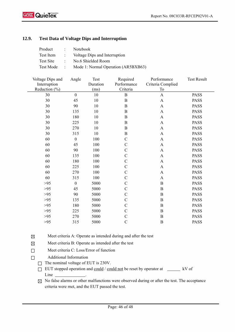
12.9. Test Data of Voltage Dips and Interruption
Product : Notebook Test Item : Voltage Dips and Interruption Test Site : No.6 Shielded Room Test Mode : Mode 1: Normal Operation (AR5BXB63)
Voltage Dips and
Interruption Reduction (%)
Angle Test Duration
(ms)
Required Performance
Criteria
Performance Criteria Complied
To
Test Result
30 0 10 B A PASS 30 45 10 B A PASS 30 90 10 B A PASS 30 135 10 B A PASS 30 180 10 B A PASS 30 225 10 B A PASS 30 270 10 B A PASS 30 315 10 B A PASS 60 0 100 C A PASS 60 45 100 C A PASS 60 90 100 C A PASS 60 135 100 C A PASS 60 180 100 C A PASS 60 225 100 C A PASS 60 270 100 C A PASS 60 315 100 C A PASS
>95 0 5000 C B PASS >95 45 5000 C B PASS >95 90 5000 C B PASS >95 135 5000 C B PASS >95 180 5000 C B PASS >95 225 5000 C B PASS >95 270 5000 C B PASS >95 315 5000 C B PASS
Meet criteria A: Operate as intended during and after the test
Meet criteria B: Operate as intended after the test
Meet criteria C: Loss/Error of function
Additional Information The nominal voltage of EUT is 230V. EUT stopped operation and could / could not be reset by operator at kV of
Line . No false alarms or other malfunctions were observed during or after the test. The acceptance
criteria were met, and the EUT passed the test.
Report No. 08C033R-RFCEP02V01-A
Page: 47 of 48
Attachment 1: EUT Test Photographs
Report No.: 08C033R-RFCEP02V01-A
Page : 1
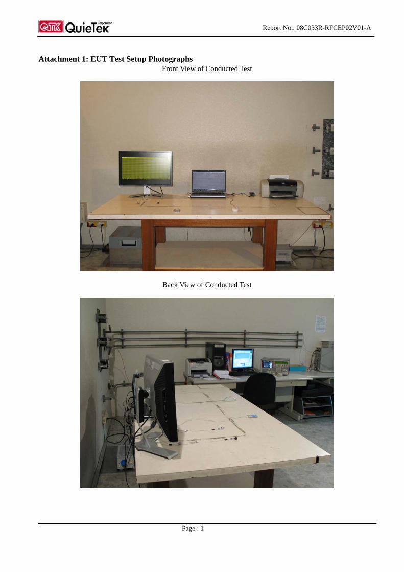
Attachment 1: EUT Test Setup Photographs Front View of Conducted Test
Back View of Conducted Test
Report No.: 08C033R-RFCEP02V01-A
Page : 2
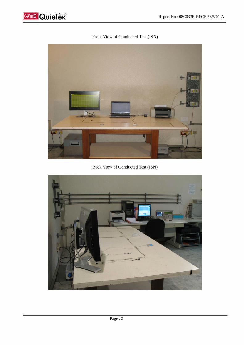
Front View of Conducted Test (ISN)
Back View of Conducted Test (ISN)
Report No.: 08C033R-RFCEP02V01-A
Page : 3
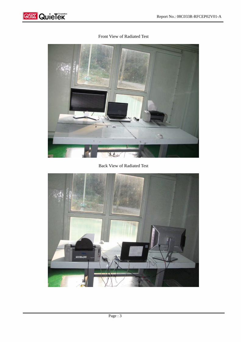
Front View of Radiated Test
Back View of Radiated Test
Report No.: 08C033R-RFCEP02V01-A
Page : 4
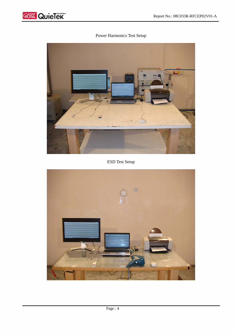
Power Harmonics Test Setup
ESD Test Setup
Report No.: 08C033R-RFCEP02V01-A
Page : 5
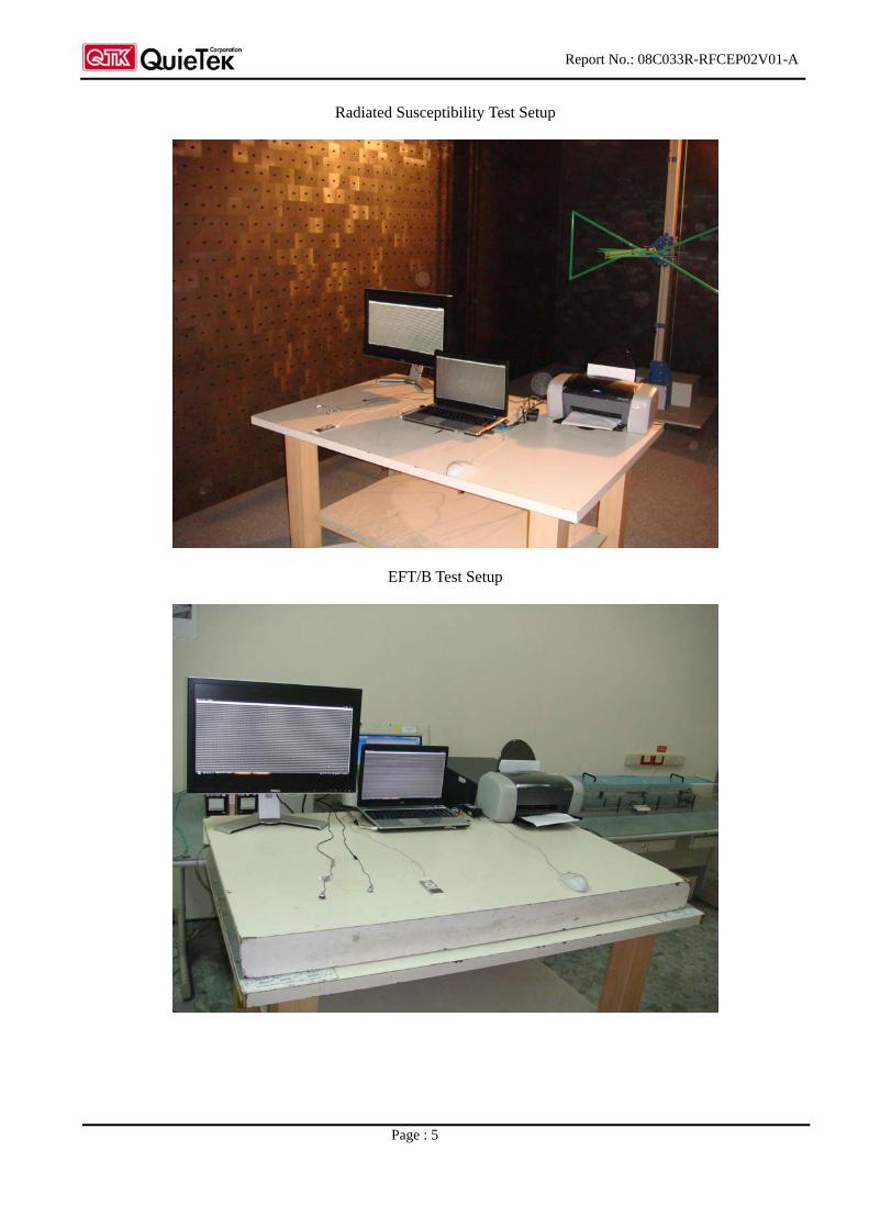
Radiated Susceptibility Test Setup
EFT/B Test Setup
Report No.: 08C033R-RFCEP02V01-A
Page : 6
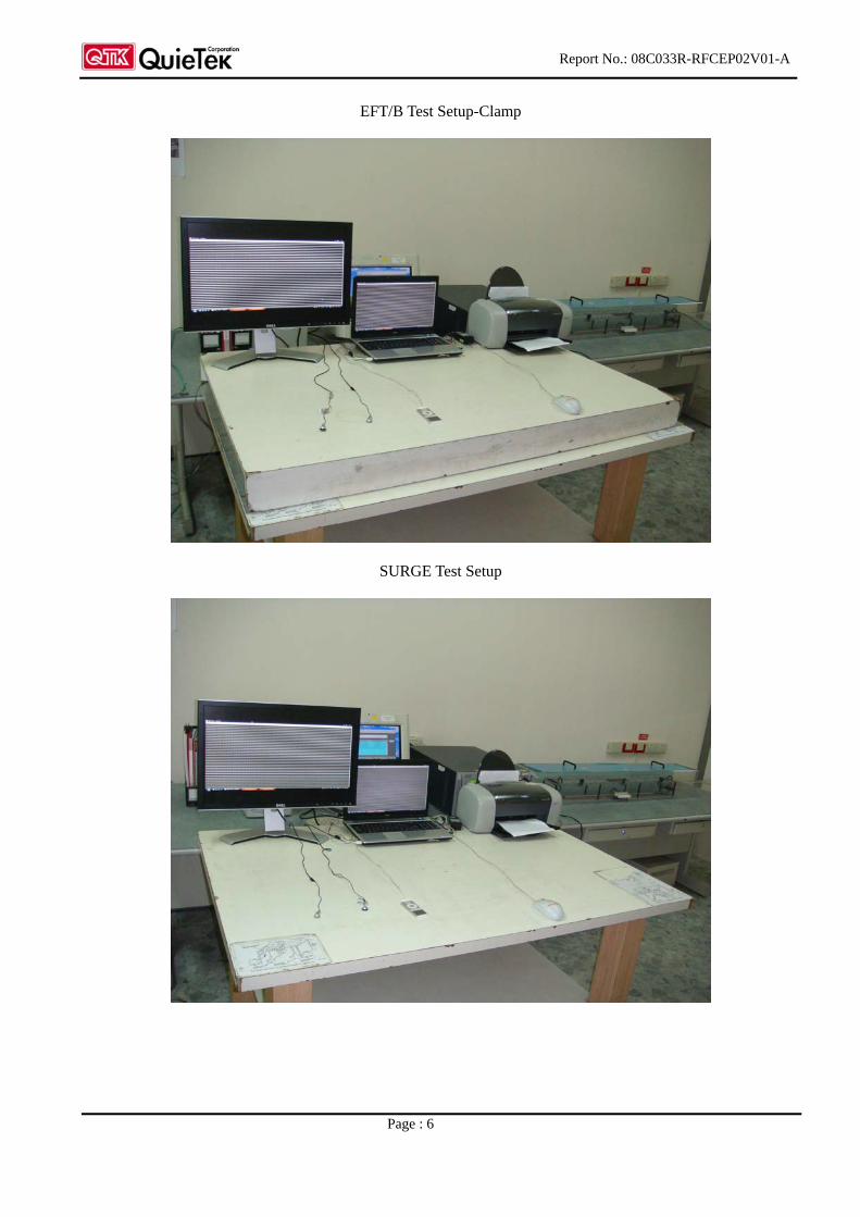
EFT/B Test Setup-Clamp
SURGE Test Setup
Report No.: 08C033R-RFCEP02V01-A
Page : 7
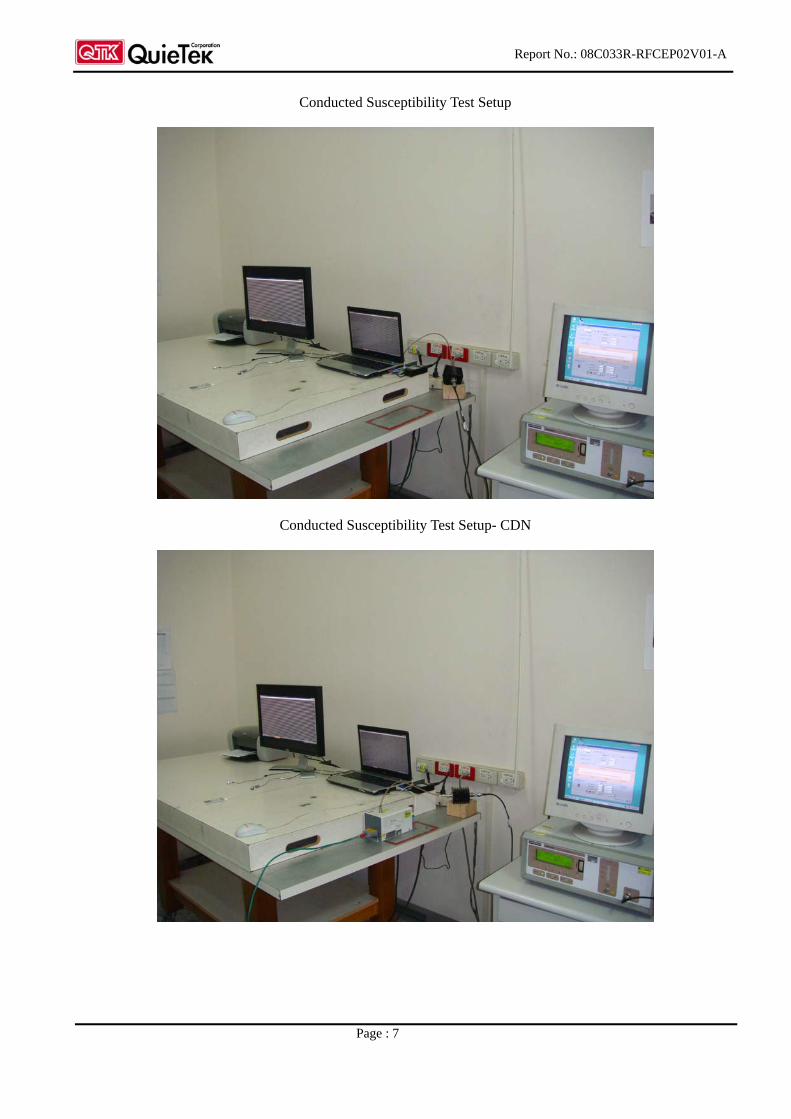
Conducted Susceptibility Test Setup
Conducted Susceptibility Test Setup- CDN
Report No.: 08C033R-RFCEP02V01-A
Page : 8
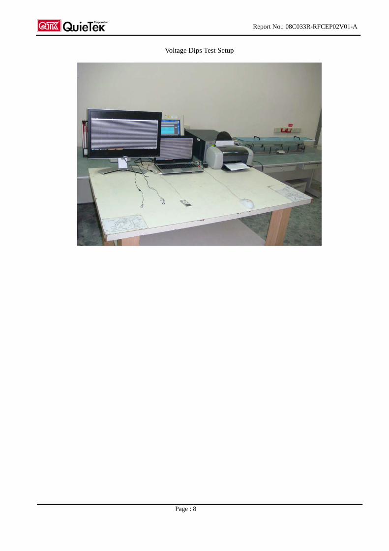
Voltage Dips Test Setup
Report No. 08C033R-RFCEP02V01-A
Page: 48 of 48
Attachment 2: EUT Detailed Photographs
Report No.: 08C033R-RFCEP02V01-A
Page: 1
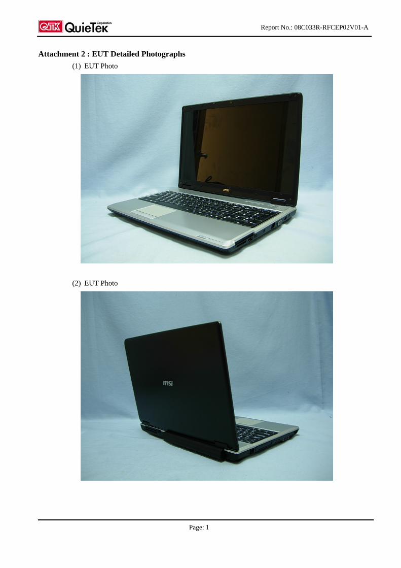
Attachment 2 : EUT Detailed Photographs
(1) EUT Photo
(2) EUT Photo
Report No.: 08C033R-RFCEP02V01-A
Page: 2
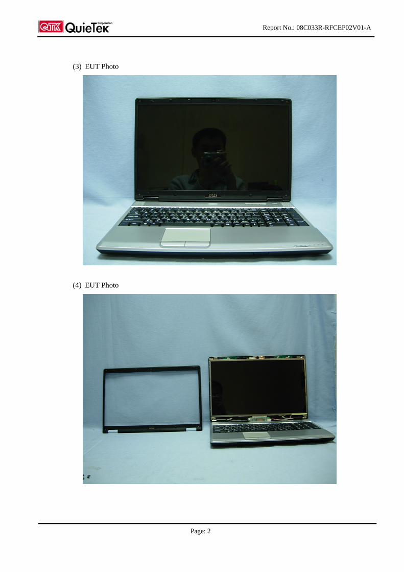
(3) EUT Photo
(4) EUT Photo
Report No.: 08C033R-RFCEP02V01-A
Page: 3
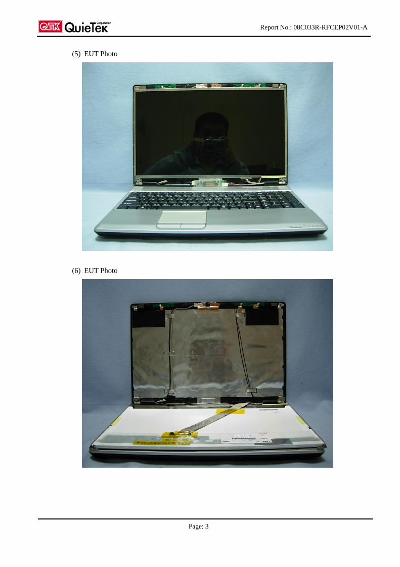
(5) EUT Photo
(6) EUT Photo
Report No.: 08C033R-RFCEP02V01-A
Page: 4
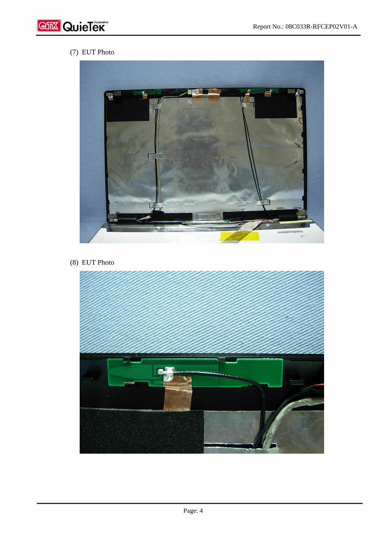
(7) EUT Photo
(8) EUT Photo
Report No.: 08C033R-RFCEP02V01-A
Page: 5
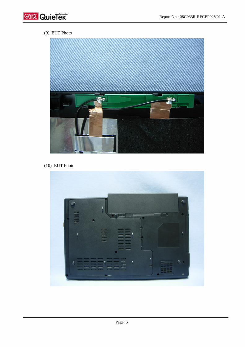
(9) EUT Photo
(10) EUT Photo
Report No.: 08C033R-RFCEP02V01-A
Page: 6
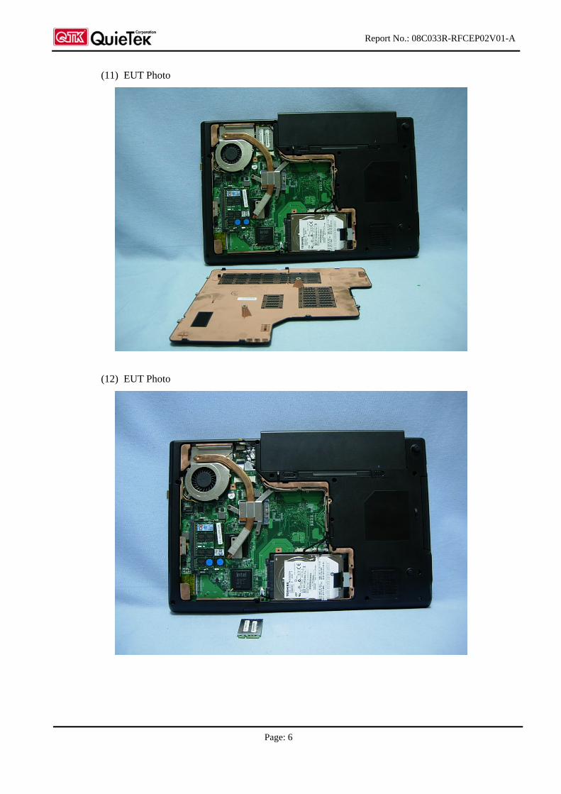
(11) EUT Photo
(12) EUT Photo
Report No.: 08C033R-RFCEP02V01-A
Page: 7
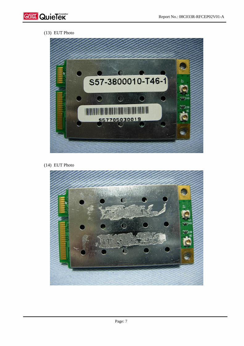
(13) EUT Photo
(14) EUT Photo
Report No.: 08C033R-RFCEP02V01-A
Page: 8
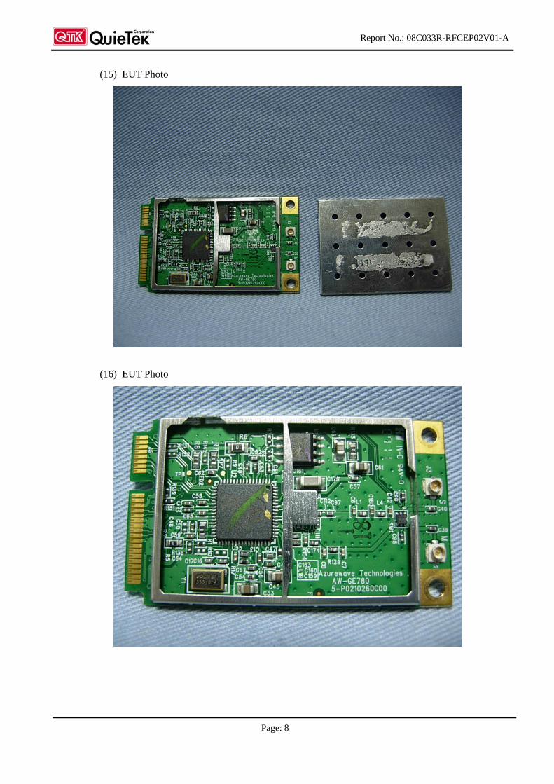
(15) EUT Photo
(16) EUT Photo
Report No.: 08C033R-RFCEP02V01-A
Page: 9
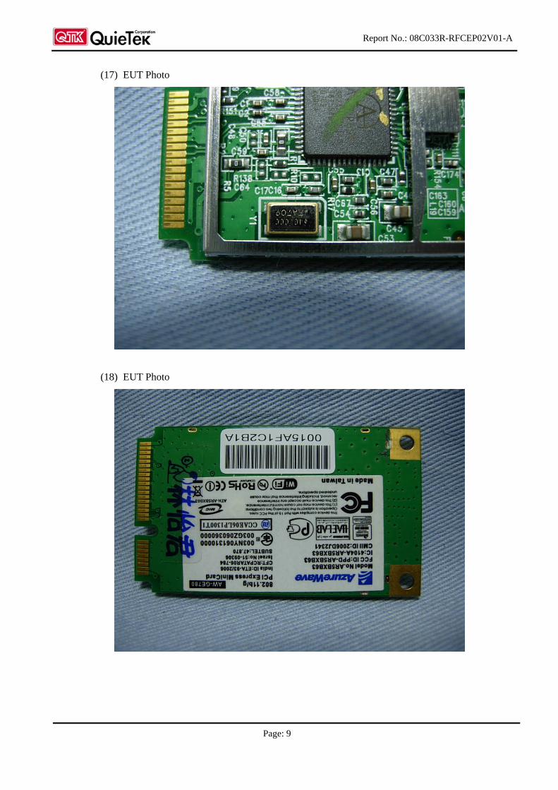
(17) EUT Photo
(18) EUT Photo
Report No.: 08C033R-RFCEP02V01-A
Page: 10
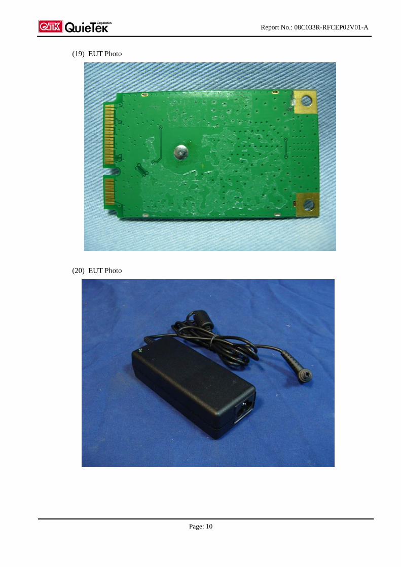
(19) EUT Photo
(20) EUT Photo
Report No.: 08C033R-RFCEP02V01-A
Page: 11
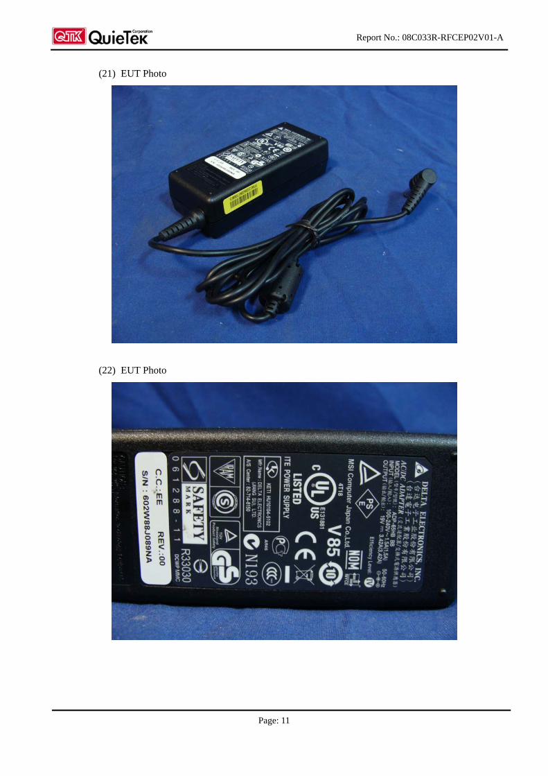
(21) EUT Photo
(22) EUT Photo
Report No.: 08C033R-RFCEP02V01-A
Page: 12
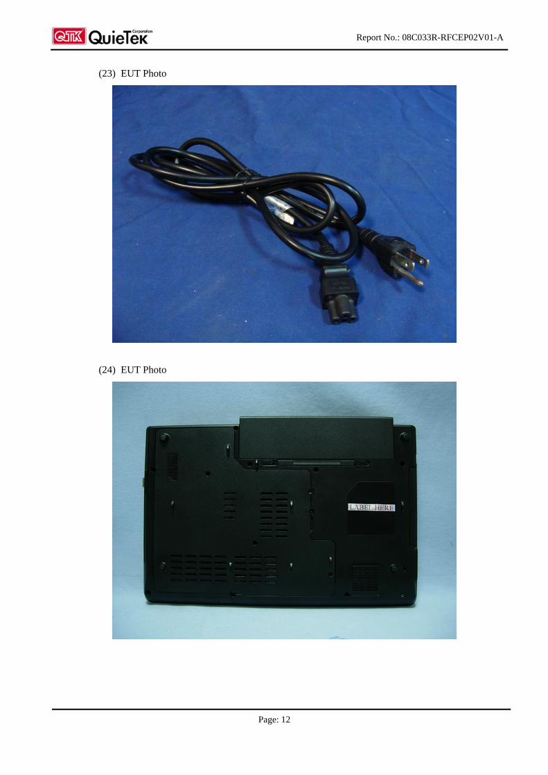
(23) EUT Photo
(24) EUT Photo