Embed Size (px)
Citation preview
09/02/11 Attn: Bernie Dow Project Name: City of Sparks TMWRF Project Number: Specification Number: Dear , Bernie Thank you for the opportunity to provide you a proposal for this project. Enclosed please find the quotation and submittal documents for the project identified above. We appreciate your continued interest in ABB Products. Please feel free to contact me with any questions you have regarding the information provided. Sincerely, Carl Wojtkowiak Intec Solutions 27 Glen Carran Cir Sparks, NV 89431 775-356-0222

Sparks WWTP 07230051 19/08/11 2
Project Quotation for Sparks WWTP
�
��������� ��� �������������������������������������
������������� ���
������������������� ���
���������� ���
��� ����� ���
��!������ ���"#���$ ��%& ' (�)����*��������+��
��� ����!�,* ������' ���+�-��+�
.��������� ��� ��/012//34��
(�5����� ��
���� ��/6�/1�1/44�
Sparks WWTP 07230051 19/08/11 3
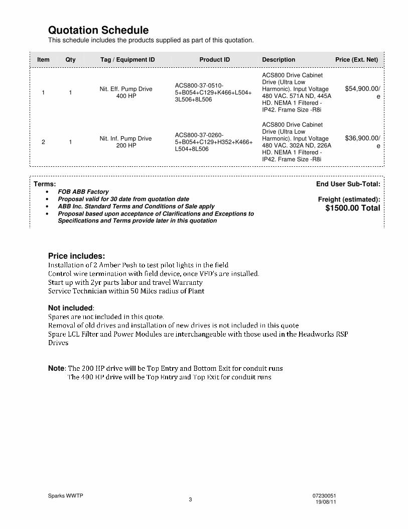
Quotation Schedule This schedule includes the products supplied as part of this quotation.
Item Qty Tag / Equipment ID Product ID Description Price (Ext. Net)
1 1 Nit. Eff. Pump Drive 400 HP
ACS800-37-0510-5+B054+C129+K466+L504+3L506+8L506
ACS800 Drive Cabinet Drive (Ultra Low Harmonic). Input Voltage 480 VAC. 571A ND, 445A HD. NEMA 1 Filtered - IP42. Frame Size -R8i
$54,900.00/e
2 1 Nit. Inf. Pump Drive 200 HP
ACS800-37-0260-5+B054+C129+H352+K466+L504+8L506
ACS800 Drive Cabinet Drive (Ultra Low Harmonic). Input Voltage 480 VAC. 302A ND, 226A HD. NEMA 1 Filtered - IP42. Frame Size -R8i
$36,900.00/e
Terms:
• FOB ABB Factory • Proposal valid for 30 date from quotation date • ABB Inc. Standard Terms and Conditions of Sale apply • Proposal based upon acceptance of Clarifications and Exceptions to
Specifications and Terms provide later in this quotation
End User Sub-Total:
Freight (estimated): $1500.00 Total
Price includes: ������������ ����������������������! �"#�%$&���'�(����#)�����*�#���+$,���-���.�/$��0�1��� �23#4�5�6�7%498 :<;�7%=>6(=7@?A;�5�B 6�;�4�5C:<;D6�E�F�;�= 8�GHG�=JI�;�KL=JM 4�5#KL=�N-O�P!Q R-BS7%=0;�5,R�6�B8�8�=SG�TU V�WSXYV#Z�[.\<]DV/^<_*`�Xa[#WSXYV�b!c�Wed�f�XgWSh#ijV�X�Wek,l c mnWSX�X@WSh�Vo`p*qrts�u�vJw>xawSv�y#z�{�vL{�|Szj}<{D~�y�{�z<�,�&�<{���w �-��|*��{����������,��|Sz�~
Not included ���#�S�%� �-�S�%�0�#�*�������%���#���S�&���j���#�������#�*�(�S��a�� �S¡�¢ £9��¤��9£�¥H¥,¦@§ ¡,� ¨-¢S©#¥.§�©�¨�ª�¢£�£�¢ ª�§���©��9¤�©#�J«¬¥,¦�§ ¡,� ¨!§�¨-©#�*ª�§�©�%£�®�¥,�S¥&§�©.ª�¯�§�¨�°�®#�*ª(�±²#³S´%µ�¶�·#¶.¸�¹�ºD»�µ´g³S¼#½H¾#¿SÀ<µ´!Á�¿�½�Â�º�µÃ-³S´�µ0¹�¼�»(µ´�Ä%Å#³S¼�Æ9µ³ Ç�º�µ�À<¹D»�Å&»�Å#¿�ÃLµÈÂ#ÃLµS½&¹�¼jÉ�Ê�Ë�ÌÈËÍ*Î9Ï<Ð�Ñ@Ò�Ó�ÔÖÕ*×Ø-Ù�Ú Û,Ü Ý
Note Þ%ßáà�â'ã,ä�ä&åÈæ�ç,è�é ê,â�ëìé�í�íî�âÈßaï9ð�ñ#ò�ó�ètô.õSò#çHöÖï*ó/ó(ï9÷øñ�ù9éDó�ú�ï�ègûJï�ò#ç�ü#éDó�è@ü#ò,ýþáÿ������������ ��� � �������������Èþ�������� �!�#"%$&��.þ������('��)��*+�(�-,.�(��(/��)���0/���1
Sparks WWTP 07230051 19/08/11 4
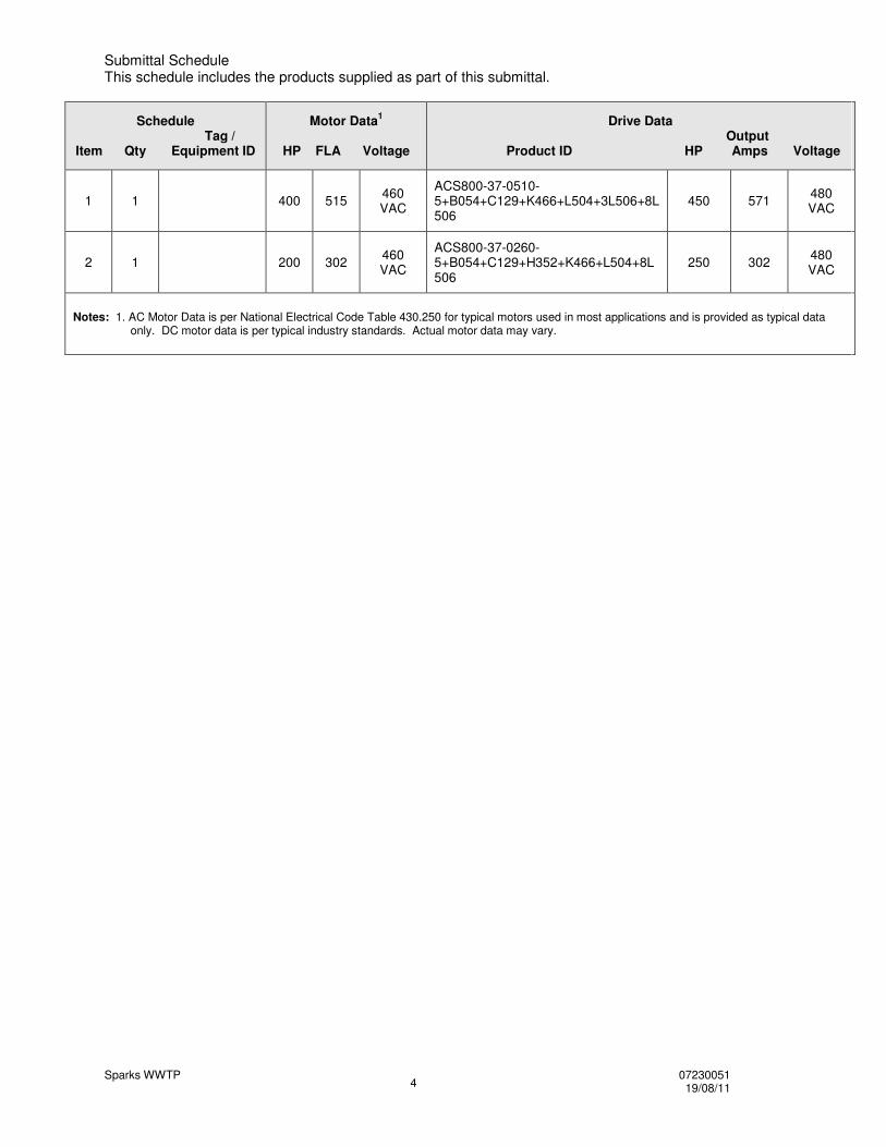
Submittal Schedule This schedule includes the products supplied as part of this submittal.
Schedule Tag /
Item Qty Equipment ID
Motor Data1
HP FLA Voltage
Drive Data Output
Product ID HP Amps Voltage
1 1 400 515 460 VAC
ACS800-37-0510-5+B054+C129+K466+L504+3L506+8L506
450 571 480 VAC
2 1 200 302 460 VAC
ACS800-37-0260-5+B054+C129+H352+K466+L504+8L506
250 302 480 VAC
Notes: 1. AC Motor Data is per National Electrical Code Table 430.250 for typical motors used in most applications and is provided as typical data only. DC motor data is per typical industry standards. Actual motor data may vary.

Sparks WWTP 07230051 19/08/11 5
Clarifications and Exceptions to Specification and Terms The comments and clarifications that follow are offered in response to the specification items identified below. Please refer to the specification section and paragraph indicated. Any contract executed based on this proposal is done based acceptance of the exceptions noted herein.
Item ID Title Clarifications and Exceptions

Sparks WWTP 07230051 19/08/11 6
Submittal Schedule Details for Item Tag / Equipment ID Product ID
1 Nit. Eff Pump Drive 400 HP ACS800-37-0510-5+B054+C129+K466+L504+3L506+8L506
Item Description
Input Voltage: 480 VAC Rated Output Current: 571 AMPS 110% 1 min - Normal Duty Construction: Cabinet Drive (Ultra Low Harmonic) Enclosure: NEMA 1 Filtered - IP42 Nominal Horsepower: 450 Frame Size: R8i Input Disconnecting Means: Fusible Disconnect Switch Bypass: None Input Impedance: 10% LCL High frequency filter Short Circuit Current Rating: Communication Protocols: EtherNet IP/Modbus/TCP Adapter Other Options: Common Mode Filter - Included, EMC/RFI Filter 2nd Envir. - Included, Coated Boards - Included, 115VAC aux ctrl voltage, US conduit plate, Load Switch, Fuses, Top Entry & Exit-UL Approved-Included, Additional I/O TB, PT100 Relay (11),
Drive Input Fuse Ratings1
Amps (600 V) Bussmann Type 1000 170M6214
Wire Size Capacities of Power Terminals
Circuit Breaker Disconnect Switch Terminal Block Overload Relay Ground Lug
N/A N/A
N/A
up to 3 x 500 MCM 52 ft-lb
3 x 2 busbar holes, 1.75" spacing, 1/2"
bolts
N/A
up to 3 x 500 MCM 52 ft-lb
Dimensions and Weights
Height in / mm
Width in / mm
Depth in / mm
Weight lbs / kg Dimension Drawing
83.9 / 2130 48.5 / 1230 25.4 / 644 2646 / 1200 68503272sheet 9
Heat Dissipation & Airflow Requirements
Power Losses Airflow Watts BTU/Hr CFM CM/Hr 18020 61500 1860 3161
Reference Drawings
Power Wiring Connection Diagram Dimension Detail
68585724 sheet 211
68585724 sheet 217 68585724 sheet 219
68585724 sheet 216, 68585724 sheet 222,
68503272sheet 9
Sparks WWTP 07230051 19/08/11 7
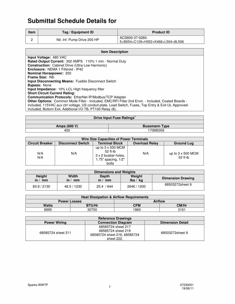
Submittal Schedule Details for Item Tag / Equipment ID Product ID
2 Nit. Inf. Pump Drive 200 HP ACS800-37-0260-5+B054+C129+H352+K466+L504+8L506
Item Description
Input Voltage: 480 VAC Rated Output Current: 302 AMPS 110% 1 min - Normal Duty Construction: Cabinet Drive (Ultra Low Harmonic) Enclosure: NEMA 1 Filtered - IP42 Nominal Horsepower: 250 Frame Size: R8i Input Disconnecting Means: Fusible Disconnect Switch Bypass: None Input Impedance: 10% LCL High frequency filter Short Circuit Current Rating: Communication Protocols: EtherNet IP/Modbus/TCP Adapter Other Options: Common Mode Filter - Included, EMC/RFI Filter 2nd Envir. - Included, Coated Boards - Included, 115VAC aux ctrl voltage, US conduit plate, Load Switch, Fuses, Top Entry & Exit-UL Approved-Included, Bottom Exit, Additional I/O TB, PT100 Relay (8),
Drive Input Fuse Ratings1
Amps (600 V) Bussmann Type 450 170M5059
Wire Size Capacities of Power Terminals
Circuit Breaker Disconnect Switch Terminal Block Overload Relay Ground Lug
N/A N/A
N/A
up to 3 x 500 MCM 52 ft-lb
3 x 2 busbar holes, 1.75" spacing, 1/2"
bolts
N/A
up to 3 x 500 MCM 52 ft-lb
Dimensions and Weights
Height in / mm
Width in / mm
Depth in / mm
Weight lbs / kg Dimension Drawing
83.9 / 2130 48.5 / 1230 25.4 / 644 2646 / 1200 68503272sheet 9
Heat Dissipation & Airflow Requirements
Power Losses Airflow Watts BTU/Hr CFM CM/Hr 8995 30700 1860 3161
Reference Drawings
Power Wiring Connection Diagram Dimension Detail
68585724 sheet 211
68585724 sheet 217 68585724 sheet 219
68585724 sheet 216, 68585724 sheet 222,
68503272sheet 9
Sparks WWTP 07230051 19/08/11 8
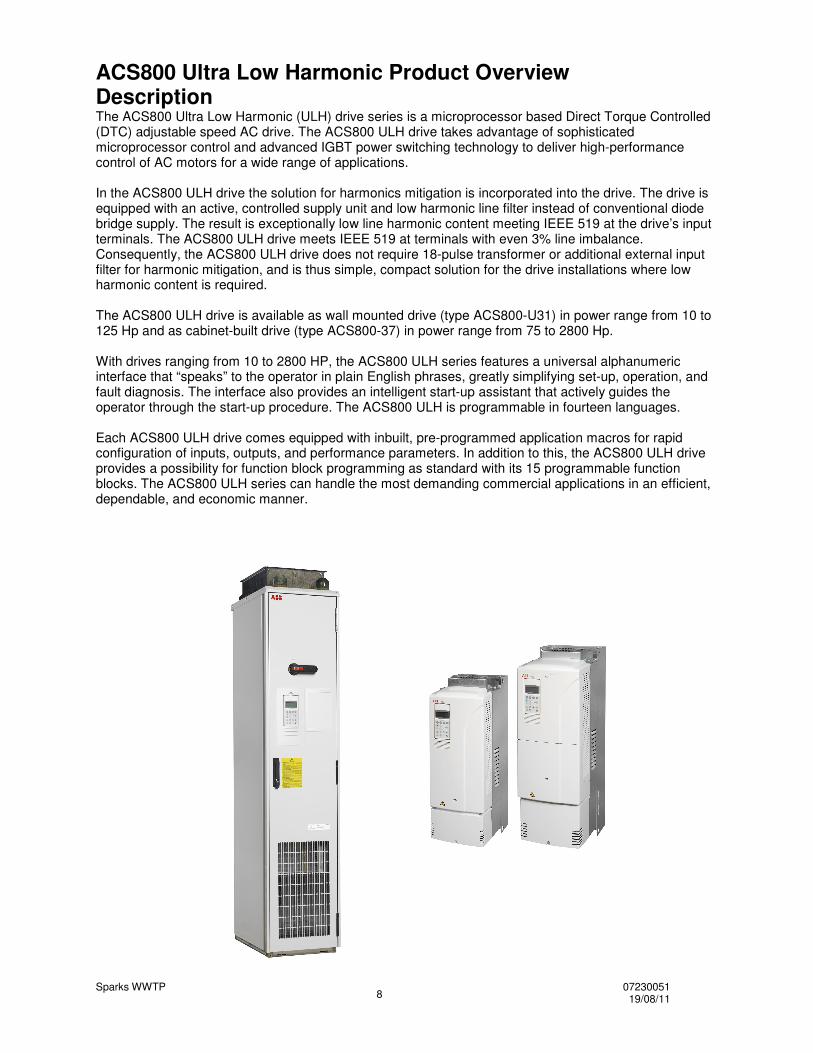
ACS800 Ultra Low Harmonic Product Overview Description The ACS800 Ultra Low Harmonic (ULH) drive series is a microprocessor based Direct Torque Controlled (DTC) adjustable speed AC drive. The ACS800 ULH drive takes advantage of sophisticated microprocessor control and advanced IGBT power switching technology to deliver high-performance control of AC motors for a wide range of applications. In the ACS800 ULH drive the solution for harmonics mitigation is incorporated into the drive. The drive is equipped with an active, controlled supply unit and low harmonic line filter instead of conventional diode bridge supply. The result is exceptionally low line harmonic content meeting IEEE 519 at the drive’s input terminals. The ACS800 ULH drive meets IEEE 519 at terminals with even 3% line imbalance. Consequently, the ACS800 ULH drive does not require 18-pulse transformer or additional external input filter for harmonic mitigation, and is thus simple, compact solution for the drive installations where low harmonic content is required. The ACS800 ULH drive is available as wall mounted drive (type ACS800-U31) in power range from 10 to 125 Hp and as cabinet-built drive (type ACS800-37) in power range from 75 to 2800 Hp. With drives ranging from 10 to 2800 HP, the ACS800 ULH series features a universal alphanumeric interface that “speaks” to the operator in plain English phrases, greatly simplifying set-up, operation, and fault diagnosis. The interface also provides an intelligent start-up assistant that actively guides the operator through the start-up procedure. The ACS800 ULH is programmable in fourteen languages. Each ACS800 ULH drive comes equipped with inbuilt, pre-programmed application macros for rapid configuration of inputs, outputs, and performance parameters. In addition to this, the ACS800 ULH drive provides a possibility for function block programming as standard with its 15 programmable function blocks. The ACS800 ULH series can handle the most demanding commercial applications in an efficient, dependable, and economic manner.
Sparks WWTP 07230051 19/08/11 9
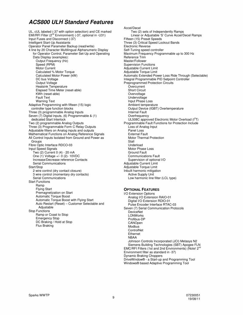
ACS800 ULH Standard Features UL, cUL labeled (-37 with option selection) and CE marked EMI/RFI Filter (2nd Environment) (-37, optional in -U31) Input Fuses and Disconnect (-37) Intelligent Start-Up Assistants Operator Panel Parameter Backup (read/write) 4 line by 20 Character Multilingual Alphanumeric Display for Operator Control, Parameter Set-Up and Operating Data Display (examples): Output Frequency (Hz) Speed (RPM) Motor Current Calculated % Motor Torque Calculated Motor Power (kW) DC bus Voltage Output Voltage Heatsink Temperature Elapsed Time Meter (reset-able) KWh (reset-able) Fault Text Warning Text Adaptive Programming with fifteen (15) logic controller type function blocks Three (3) programmable Analog Inputs Seven (7) Digital inputs, (6) Programmable & (1) dedicated Start Interlock Two (2) programmable Analog Outputs Three (3) Programmable Form C Relay Outputs Adjustable filters on Analog inputs and outputs Mathematical Functions on Analog Reference Signals All Control Inputs Isolated from Ground and Power as Groups Fibre Optic Interface RDCO-03 Input Speed Signals Two (2) Current 0 (4) - 20 mA One (1) Voltage +/- 0 (2)- 10VDC Increase/Decrease reference Contacts Serial Communications Start/Stop 2 wire control (dry contact closure) 3 wire control (momentary dry contacts) Serial Communications Start Functions Ramp Flying Start Premagnetization on Start Automatic Torque Boost Automatic Torque Boost with Flying Start Auto Restart (Reset) – Customer Selectable and Adjustable Stop Functions Ramp or Coast to Stop Emergency Stop DC Braking / Hold at Stop Flux Braking
Accel/Decel Two (2) sets of Independently Ramps Linear or Adjustable ‘S’ Curve Accel/Decel Ramps Fifteen (15) Preset Speeds Three (3) Critical Speed Lockout Bands Electronic Reverse Self-Tuning speed controller Maximum Frequency Programmable up to 300 Hz Reference Trim Master/Follower Supervision Functions Adjustable Current Limit Adjustable Torque Limit Automatic Extended Power Loss Ride Through (Selectable) Integral Programmable PID Setpoint Controller Preprogrammed Protection Circuits Overcurrent Short Circuit Overvoltage Undervoltage Input Phase Loss Ambient temperature Output Device (IGBT) Overtemperature Internal Fault Overfrequency UL508C approved Electronic Motor Overload (I2T) Programmable Fault Functions for Protection Include Loss of Analog Input Panel Loss External Fault Motor Thermal Protection Stall Underload Motor Phase Loss Ground Fault Communications Fault Supervision of optional I/O Adjustable Current Limit Adjustable Torque Limit Inbuilt harmonic mitigation Active Supply Unit Low harmonic line filter (LCL type) OPTIONAL FEATURES I/O Extension Options Analog I/O Extension RAIO-01 Digital I/O Extension RDIO-01 Pulse Encoder Interface RTAC-03 Seven (7) Serial Communication Protocols DeviceNet LONWorks Profibus-DP CANOpen Modbus ControlNet Ethernet NBAA Johnson Controls Incorporated (JCI) Metasys N2 Siemens Building Technologies (SBT) Apogee FLN EMC/RFI Filters (1st and 2nd Environments) (Note! 2nd Environment filter as standard in -37) Dynamic Braking Choppers DriveWindow® - a Start-up and Programming Tool Windows® based Adaptive Programming Tool
Sparks WWTP 07230051 19/08/11 10
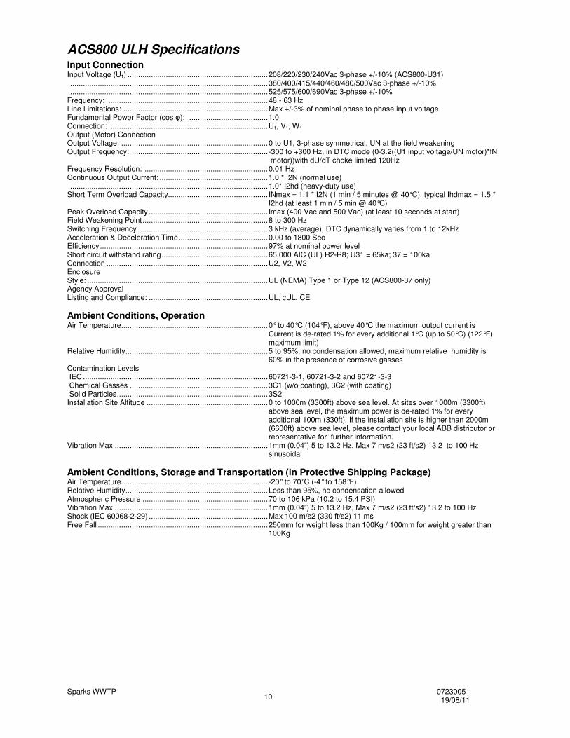
ACS800 ULH Specifications Input Connection Input Voltage (U1) .................................................................. 208/220/230/240Vac 3-phase +/-10% (ACS800-U31) .............................................................................................. 380/400/415/440/460/480/500Vac 3-phase +/-10% .............................................................................................. 525/575/600/690Vac 3-phase +/-10% Frequency: ........................................................................... 48 - 63 Hz Line Limitations: .................................................................... Max +/-3% of nominal phase to phase input voltage Fundamental Power Factor (cos �): ..................................... 1.0 Connection: .......................................................................... U1, V1, W1 Output (Motor) Connection Output Voltage: ..................................................................... 0 to U1, 3-phase symmetrical, UN at the field weakening Output Frequency: ................................................................ -300 to +300 Hz, in DTC mode (0-3.2((U1 input voltage/UN motor)*fN
motor))with dU/dT choke limited 120Hz Frequency Resolution: .......................................................... 0.01 Hz Continuous Output Current: ................................................... 1.0 * I2N (normal use) .............................................................................................. 1.0* I2hd (heavy-duty use) Short Term Overload Capacity ............................................... INmax = 1.1 * I2N (1 min / 5 minutes @ 40°C), typical Ihdmax = 1.5 *
I2hd (at least 1 min / 5 min @ 40°C) Peak Overload Capacity ........................................................ Imax (400 Vac and 500 Vac) (at least 10 seconds at start) Field Weakening Point ........................................................... 8 to 300 Hz Switching Frequency ............................................................. 3 kHz (average), DTC dynamically varies from 1 to 12kHz Acceleration & Deceleration Time .......................................... 0.00 to 1800 Sec Efficiency ............................................................................... 97% at nominal power level Short circuit withstand rating .................................................. 65,000 AIC (UL) R2-R8; U31 = 65ka; 37 = 100ka Connection ............................................................................ U2, V2, W2 Enclosure Style: ..................................................................................... UL (NEMA) Type 1 or Type 12 (ACS800-37 only) Agency Approval Listing and Compliance: ........................................................ UL, cUL, CE Ambient Conditions, Operation Air Temperature ..................................................................... 0° to 40°C (104°F), above 40°C the maximum output current is
Current is de-rated 1% for every additional 1°C (up to 50°C) (122°F) maximum limit)
Relative Humidity ................................................................... 5 to 95%, no condensation allowed, maximum relative humidity is 60% in the presence of corrosive gasses
Contamination Levels IEC ....................................................................................... 60721-3-1, 60721-3-2 and 60721-3-3 Chemical Gasses ................................................................. 3C1 (w/o coating), 3C2 (with coating) Solid Particles ....................................................................... 3S2 Installation Site Altitude ......................................................... 0 to 1000m (3300ft) above sea level. At sites over 1000m (3300ft)
above sea level, the maximum power is de-rated 1% for every additional 100m (330ft). If the installation site is higher than 2000m (6600ft) above sea level, please contact your local ABB distributor or representative for further information.
Vibration Max ........................................................................ 1mm (0.04”) 5 to 13.2 Hz, Max 7 m/s2 (23 ft/s2) 13.2 to 100 Hz sinusoidal
Ambient Conditions, Storage and Transportation (in Protective Shipping Package) Air Temperature ..................................................................... -20° to 70°C (-4° to 158°F) Relative Humidity ................................................................... Less than 95%, no condensation allowed Atmospheric Pressure ........................................................... 70 to 106 kPa (10.2 to 15.4 PSI) Vibration Max ........................................................................ 1mm (0.04”) 5 to 13.2 Hz, Max 7 m/s2 (23 ft/s2) 13.2 to 100 Hz Shock (IEC 60068-2-29) ........................................................ Max 100 m/s2 (330 ft/s2) 11 ms Free Fall ................................................................................ 250mm for weight less than 100Kg / 100mm for weight greater than
100Kg
Sparks WWTP 07230051 19/08/11 11
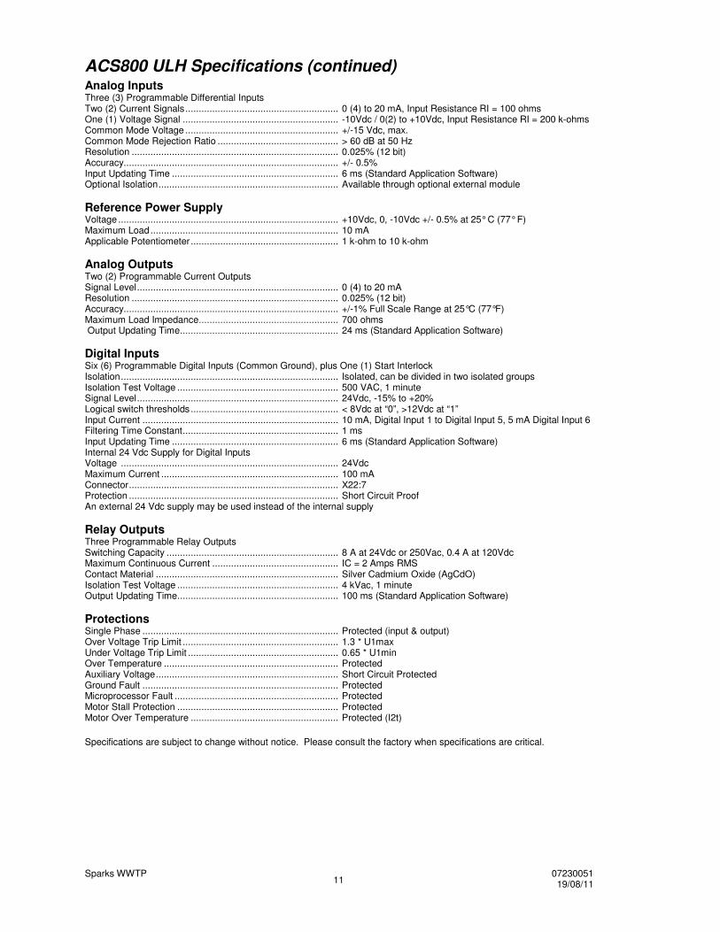
ACS800 ULH Specifications (continued) Analog Inputs Three (3) Programmable Differential Inputs Two (2) Current Signals ......................................................... 0 (4) to 20 mA, Input Resistance RI = 100 ohms One (1) Voltage Signal .......................................................... -10Vdc / 0(2) to +10Vdc, Input Resistance RI = 200 k-ohms Common Mode Voltage ......................................................... +/-15 Vdc, max. Common Mode Rejection Ratio ............................................. > 60 dB at 50 Hz Resolution ............................................................................. 0.025% (12 bit) Accuracy................................................................................ +/- 0.5% Input Updating Time .............................................................. 6 ms (Standard Application Software) Optional Isolation ................................................................... Available through optional external module Reference Power Supply Voltage .................................................................................. +10Vdc, 0, -10Vdc +/- 0.5% at 25° C (77° F) Maximum Load ...................................................................... 10 mA Applicable Potentiometer ....................................................... 1 k-ohm to 10 k-ohm Analog Outputs Two (2) Programmable Current Outputs Signal Level ........................................................................... 0 (4) to 20 mA Resolution ............................................................................. 0.025% (12 bit) Accuracy................................................................................ +/-1% Full Scale Range at 25°C (77°F) Maximum Load Impedance .................................................... 700 ohms Output Updating Time ........................................................... 24 ms (Standard Application Software) Digital Inputs Six (6) Programmable Digital Inputs (Common Ground), plus One (1) Start Interlock Isolation ................................................................................. Isolated, can be divided in two isolated groups Isolation Test Voltage ............................................................ 500 VAC, 1 minute Signal Level ........................................................................... 24Vdc, -15% to +20% Logical switch thresholds ....................................................... < 8Vdc at “0”, >12Vdc at “1” Input Current ......................................................................... 10 mA, Digital Input 1 to Digital Input 5, 5 mA Digital Input 6 Filtering Time Constant .......................................................... 1 ms Input Updating Time .............................................................. 6 ms (Standard Application Software) Internal 24 Vdc Supply for Digital Inputs Voltage ................................................................................. 24Vdc Maximum Current .................................................................. 100 mA Connector .............................................................................. X22:7 Protection .............................................................................. Short Circuit Proof An external 24 Vdc supply may be used instead of the internal supply Relay Outputs Three Programmable Relay Outputs Switching Capacity ................................................................ 8 A at 24Vdc or 250Vac, 0.4 A at 120Vdc Maximum Continuous Current ............................................... IC = 2 Amps RMS Contact Material .................................................................... Silver Cadmium Oxide (AgCdO) Isolation Test Voltage ............................................................ 4 kVac, 1 minute Output Updating Time ............................................................ 100 ms (Standard Application Software) Protections Single Phase ......................................................................... Protected (input & output) Over Voltage Trip Limit .......................................................... 1.3 * U1max Under Voltage Trip Limit ........................................................ 0.65 * U1min Over Temperature ................................................................. Protected Auxiliary Voltage .................................................................... Short Circuit Protected Ground Fault ......................................................................... Protected Microprocessor Fault ............................................................. Protected Motor Stall Protection ............................................................ Protected Motor Over Temperature ....................................................... Protected (I2t)
Specifications are subject to change without notice. Please consult the factory when specifications are critical.
Sparks WWTP 07230051 19/08/11 12
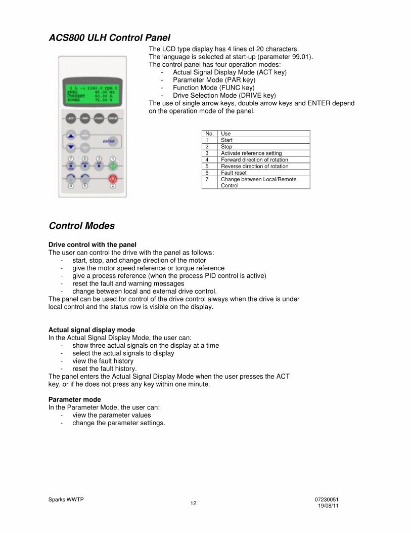
ACS800 ULH Control Panel The LCD type display has 4 lines of 20 characters. The language is selected at start-up (parameter 99.01). The control panel has four operation modes:
- Actual Signal Display Mode (ACT key) - Parameter Mode (PAR key) - Function Mode (FUNC key) - Drive Selection Mode (DRIVE key)
The use of single arrow keys, double arrow keys and ENTER depend on the operation mode of the panel.
No. Use 1 Start 2 Stop 3 Activate reference setting 4 Forward direction of rotation 5 Reverse direction of rotation 6 Fault reset 7 Change between Local/Remote
Control
Control Modes Drive control with the panel The user can control the drive with the panel as follows:
- start, stop, and change direction of the motor - give the motor speed reference or torque reference - give a process reference (when the process PID control is active) - reset the fault and warning messages - change between local and external drive control.
The panel can be used for control of the drive control always when the drive is under local control and the status row is visible on the display. Actual signal display mode In the Actual Signal Display Mode, the user can:
- show three actual signals on the display at a time - select the actual signals to display - view the fault history - reset the fault history.
The panel enters the Actual Signal Display Mode when the user presses the ACT key, or if he does not press any key within one minute. Parameter mode In the Parameter Mode, the user can:
- view the parameter values - change the parameter settings.
Sparks WWTP 07230051 19/08/11 13
Control Modes (continued) The panel enters the Parameter Mode when the user presses the PAR key. Function mode In the Function Mode, the user can:
- start a guided procedure for adjusting the drive settings (assistants) - upload the drive parameter values and motor data from the drive to the panel. - download group 1 to 97 parameter values from the panel to the drive. 1) - adjust the contrast of the display.
The panel enters the Function Mode when the user presses the FUNC key.
Cable Connections
Terminal Description Note U1, V1, W1 3~ power supply input L1, L2, L3 3~ power supply input PE / GND Protective Ground Follow local rules for cable size. U2, V2, W2 Power output to motor Uc+, Uc- DC bus Not accessible in ACS800-37 X20 to X23 Control Wiring Low voltage control – Use shielded cable X25 to X27 Control Wiring Low voltage or 115VAC
Follow local codes for cable size. To avoid electromagnetic interference, use separate metallic conduits for input power wiring, motor wiring, control and communications wiring. Keep these four classes of wiring separated in situations where the wiring is not enclosed in metallic conduit. Also, keep 115VAC control wiring separated from low voltage control wiring and power wiring. Use shielded cable for control wiring. Ampacity is based on the use of 60 °C rated power cable up to 100 Amps (75 °C over 100 Amps). Refer to the included tables for current ratings, fuse recommendations and maximum wire size capacities and tightening torques for the terminals. The ACS800 ULH drive is suitable for use on a circuit capable of delivering not more than 100,000 RMS symmetrical amperes, 600V maximum. The ACS800 ULH has an electronic motor protection feature that complies with the requirements of the National Electric Code (NEC) 430.126(A)(2). When this feature is selected and properly adjusted. Additional overload protection is not required unless more than one motor is connected to the drive or unless additional protection is required by applicable safety regulations. For CE installation requirements, see ABB publication CE-US-02 “CE Council Directives and Variable Speed Drives.” Contact your local ABB representative for specific IEC installation instructions.
Sparks WWTP 07230051 19/08/11 14
ACS800 Control Terminals
X20 Identification Description
1 VREF- Reference voltage -10 VDC, 1 kohm �RL � 10 kohm
2 AGND X21 Identification Description 1 VREF+ Reference voltage 10 VDC, 1 kohm �RL � 2 AGND 10 kohm 3 AI1+ Speed reference 0(2) .. 10 V, Rin > 200 4 AI1- kohm 5 AI2+ By default, not in use. 0(4) … 20 mA, Rin = 6 AI2- 100 ohm 7 AI3+ By default, not in use. 0(4) … 20 mA, Rin = 8 AI3- 100 ohm 9 AO1+ Motor spped 0(4) … 20 mA = 0...motor 10 AO1- Nom. speed, RL < 700 ohm 11 AO2+ 12 AO2- X22 Identification Description
1 DI1 Start ( )
2 DI2 Stop ( ) 3 DI3 Forward/Reverse 1) 4 DI4 Acceleration & deceleration select 2) 5 DI5 Acceleration & deceleration select 2) 6 DI6 Constant speed select 3) 7 +24VD +24 VDC max. 100 mA 8 +24VD 9 DGND1 Digital ground 10 DGND2 Digital ground 11 DIIL Start interlock (0 = stop) 4) X23 Identification Description 1 +24V Auxiliary voltage output, non-isolated, 2 GND 24 VDC 250 mA X25 Identification Description 1 RO1 2 RO1 Relay output 1: ready 3 RO1 X26 Identification Description 1 RO2 2 RO2 Relay output 2: running 3 RO2 X27 Identification Description 1 RO3 2 RO3 Relay output 3: fault (-1) 3 RO3
Notes: 1) Only effective if par. 10.03 is set to REQUEST by the user. 2) 0 = open, 1 = closed DI4 ..... Ramp times according to 0….. .... parameters 22.02 and 22.03 1 ......... parameters 22.04 and 22.05 3) See par. group 12 CONSTANT SPEEDS. DI5 DI6 Operation 1 0 Constant speed 1 0 ....... 1 Constant speed 2 1 ....... 1 Constant speed 3 4) See parameter 21.09 START
Cabinet-built Drive Standard Features
ACS800 ULH Cabinet-built Drive – Overview
Sparks WWTP 07230051 19/08/11 15
The cabinet-built drive is ACS800 ULH drive in an integrated UL Type 1 or UL Type 12 enclosure with an input disconnect switch, fuses and either contactor or circuit breaker (depending on power rating of the drive). The enclosure is of floor standing type. The ACS800 ULH cabinet-built drive provides an input disconnect switch or circuit breaker with door mounted, interlocked operator (padlockable in the OFF position), a local operator keypad with indicating lights, and provisions for optional auxiliary devices and for external control connections.
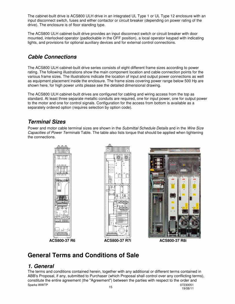
Cable Connections The ACS800 ULH cabinet-built drive series consists of eight different frame sizes according to power rating. The following illustrations show the main component location and cable connection points for the various frame sizes. The illustrations indicate the location of input and output power connections as well as equipment placement inside the enclosure. The frame sizes covering power range below 500 Hp are shown here, for high power units please see the detailed dimensional drawing. The ACS800 ULH cabinet-built drives are configured for cabling and wiring access from the top as standard. At least three separate metallic conduits are required, one for input power, one for output power to the motor and one for control signals. Configuration for the access from bottom is available as a separately ordered option (requires selection by option code).
Terminal Sizes Power and motor cable terminal sizes are shown in the Submittal Schedule Details and in the Wire Size Capacities of Power Terminals Table. The table also lists torque that should be applied when tightening the connections.
ACS800-37 R6
ACS800-37 R7i
ACS800-37 R8i
General Terms and Conditions of Sale 1. General The terms and conditions contained herein, together with any additional or different terms contained in ABB's Proposal, if any, submitted to Purchaser (which Proposal shall control over any conflicting terms), constitute the entire agreement (the "Agreement") between the parties with respect to the order and
Sparks WWTP 07230051 19/08/11 16
supersede all prior communications and agreements regarding the order. Acceptance by ABB of the order, or Purchaser's acceptance of ABB's Proposal, is expressly limited to and conditioned upon Purchaser's acceptance of these terms and conditions, payment for or acceptance of any performance by ABB being acceptance. These terms and conditions may not be changed or superseded by any different or additional terms and conditions proposed by Purchaser to which terms ABB hereby objects. Unless the context otherwise requires, the term "Equipment" as used herein means all of the equipment, parts, accessories sold, and all software and software documentation, if any, licensed to Purchaser by ABB ("Software") under the order. Unless the context otherwise requires, the term "Services" as used herein means all labor, supervisory, technical and engineering, installation, repair, consulting or other services provided by ABB under the order. As used herein, the term "Purchaser" shall include the initial end use of the Equipment and/or services; provided, however, that Paragraph 13(a) shall apply exclusively to the initial end user.
2. Prices (a) Unless otherwise specified in writing, all Proposals expire thirty (30) days from the date thereof. (b) Unless otherwise stated herein, Services prices are based on normal business hours (8 a.m. to 5 p.m. Monday through Friday). Overtime and Saturday hours will be billed at one and one-half (1 1/2) times the hourly rate; and Sunday hours will be billed at two (2) times the hourly rate; holiday hours will be billed at three (3) times the hourly rate. If a Services rate sheet is attached hereto, the applicable Services rates shall be those set forth in the rate sheet. Rates are subject to change without notice. (c) The price does not include any federal, state or local property, license, privilege, sales, use, excise, gross receipts, or other like taxes which may now or hereafter be applicable. Purchaser agrees to pay or reimburse any such taxes which ABB or its suppliers are required to pay or collect. If Purchaser is exempt from the payment of any tax or holds a direct payment permit, Purchaser shall, upon order placement, provide ABB a copy, acceptable to the relevant governmental authorities of any such certificate or permit. (d) The price includes customs duties and other importation or exportation fees, if any, at the rates in effect on the date of ABB’s Proposal. Any change after that date in such duties, fees, or rates, shall increase the price by ABB's additional cost.
3. Payment (a) Unless specified to the contrary in writing by ABB, payment terms are net cash, payable without offset, in United States Dollars, 30 days from date of invoice by wire transfer to the account designated by ABB in the Proposal. (b) If in the judgment of ABB the financial condition of Purchaser at any time prior to delivery does not justify the terms of payment specified, ABB may require payment in advance, payment security satisfactory to ABB, or may terminate the order, whereupon ABB shall be entitled to receive reasonable cancellation charges. If delivery is delayed by Purchaser, payment shall be due on the date ABB is prepared to make delivery. Delays in delivery or nonconformities in any installments delivered shall not relieve Purchaser of its obligation to accept and pay for remaining installments. (c) Purchaser shall pay, in addition to the overdue payment, a late charge equal to the lesser of 1 1/2% per month or any part thereof or the highest applicable rate allowed by law on all such overdue amounts plus ABB's attorneys' fees and court costs incurred in connection with collection.
4. Changes (a) Any changes requested by Purchaser affecting the ordered scope of work must be accepted by ABB and resulting adjustments to affected provisions, including price, schedule, and guarantees mutually agreed in writing prior to implementation of the change. (b) ABB may, at its expense, make such changes in the Equipment or Services as it deems necessary, in its sole discretion, to conform the Equipment or Services to the applicable specifications. If Purchaser objects to any such changes, ABB shall be relieved of its obligation to conform to the applicable specifications to the extent that conformance may be affected by such objection.
5. Delivery (a) All Equipment manufactured, assembled or warehoused in the continental United States is delivered F.O.B. point of shipment. Equipment shipped from outside the continental United States is delivered F.O.B. United States port of entry. Purchaser shall be responsible for any and all demurrage or detention charges.
Sparks WWTP 07230051 19/08/11 17
(b) If the scheduled delivery of Equipment is delayed by Purchaser or by Force Majeure, ABB may move the Equipment to storage for the account of and at the risk of Purchaser whereupon it shall be deemed to be delivered. (c) Shipping and delivery dates are contingent upon Purchaser's timely approvals and delivery by Purchaser of any documentation required for ABB's performance hereunder. (d) Claims for shortages or other errors in delivery must be made in writing to ABB within ten days of delivery. Equipment may not be returned except with the prior written consent of and subject to terms specified by ABB. Claims for damage after delivery shall be made directly by Purchaser with the common carrier.
6. Title & Risk of Loss Except with respect to Software (for which title shall not pass, use being licensed) title to Equipment shall remain in ABB until fully paid for. Notwithstanding any agreement with respect to delivery terms or payment of transportation charges, risk of loss or damage shall pass to Purchaser upon delivery.
7. Inspection, Testing and Acceptance (a) Any inspection by Purchaser of Equipment on ABB's premises shall be scheduled in advance to be performed during normal working hours. (b) If the order provides for factory acceptance testing, ABB shall notify Purchaser when ABB will conduct such testing prior to shipment. Unless Purchaser states specific objections in writing within ten (10) days after completion of factory acceptance testing, completion of the acceptance test constitutes Purchaser's factory acceptance of the Equipment and its authorization for shipment. (c) If the order provides for site acceptance testing, testing will be performed by ABB personnel to verify that the Equipment has arrived at site complete, without physical damage, and in good operating condition. Completion of site acceptance testing constitutes full and final acceptance of the Equipment. If, through no fault of ABB, acceptance testing is not completed within thirty (30) days after arrival of the Equipment at the site, the site acceptance test shall be deemed completed and the Equipment shall be deemed accepted.
8. Warranties and Remedies (a) Equipment and Services Warranty. ABB warrants that Equipment (excluding Software, which is warranted as specified in paragraph (d) below) shall be delivered free of defects in material and workmanship and that Services shall be free of defects in workmanship. The Warranty Remedy Period for Equipment (excluding Software, Spare Parts and Refurbished or Repaired Parts) shall end twelve (12) months after installation or eighteen (18) months after date of shipment, whichever first occurs. The Warranty Remedy Period for new spare parts shall end twelve (12) months after date of shipment. The Warranty Remedy Period for refurbished or repaired parts shall end ninety (90) days after date of shipment. The Warranty Remedy Period for Services shall end ninety (90) days after the date of completion of Services. (b) Equipment and Services Remedy. If a nonconformity to the foregoing warranty is discovered in the Equipment or Services during the applicable Warranty Remedy Period, as specified above, under normal and proper use and provided the Equipment has been properly stored, installed, operated and maintained and written notice of such nonconformity is provided to ABB promptly after such discovery and within the applicable Warranty Remedy Period, ABB shall, at its option, either (i) repair or replace the nonconforming portion of the Equipment or re-perform the nonconforming Services or (ii) refund the portion of the price applicable to the nonconforming portion of Equipment or Services. If any portion of the Equipment or Services so repaired, replaced or re-performed fails to conform to the foregoing warranty, and written notice of such nonconformity is provided to ABB promptly after discovery and within the original Warranty Remedy Period applicable to such Equipment or Services or 30 days from completion of such repair, replacement or re-performance, whichever is later, ABB will repair or replace such nonconforming Equipment or re-perform the nonconforming Services. The original Warranty Remedy Period shall not otherwise be extended. (c) Exceptions. ABB shall not be responsible for providing working access to the nonconforming Equipment, including disassembly and re-assembly of non-ABB supplied equipment, or for providing transportation to or from any repair facility, all of which shall be at Purchaser's risk and expense. ABB shall have no obligation hereunder with respect to any Equipment which (i) has been improperly repaired or altered; (ii) has been subjected to misuse, negligence or accident; (iii) has been used in a manner contrary to ABB's instructions; (iv) is comprised of materials provided by or a design specified by
Sparks WWTP 07230051 19/08/11 18
Purchaser; or (v) has failed as a result of ordinary wear and tear. Equipment supplied by ABB but manufactured by others is warranted only to the extent of the manufacturer’s warranty, and only the remedies, if any, provided by the manufacturer will be allowed. (d) Software Warranty and Remedies. ABB warrants that, except as specified below, the Software will, when properly installed, execute in accordance with ABB's published specification. If a nonconformity to the foregoing warranty is discovered during the period ending one (1) year after the date of shipment and written notice of such nonconformity is provided to ABB promptly after such discovery and within that period, including a description of the nonconformity and complete information about the manner of its discovery, ABB shall correct the nonconformity by, at its option, either (i) modifying or making available to the Purchaser instructions for modifying the Software; or (ii) making available at ABB's facility necessary corrected or replacement programs. ABB shall have no obligation with respect to any nonconformities resulting from (i) unauthorized modification of the Software or (ii) Purchaser-supplied software or interfacing. ABB does not warrant that the functions contained in the software will operate in combinations which may be selected for use by the Purchaser, or that the software products are free from errors in the nature of what is commonly categorized by the computer industry as "bugs". (e) THE FOREGOING WARRANTIES ARE EXCLUSIVE AND IN LIEU OF ALL OTHER WARRANTIES OF QUALITY AND PERFORMANCE, WHETHER WRITTEN, ORAL OR IMPLIED, AND ALL OTHER WARRANTIES INCLUDING ANY IMPLIED WARRANTIES OF MERCHANTABILITY OR FITNESS FOR A PARTICULAR PURPOSE OR USAGE OF TRADE ARE HEREBY DISCLAIMED. THE REMEDIES STATED HEREIN CONSTITUTE PURCHASER’S EXCLUSIVE REMEDIES AND ABB’S ENTIRE LIABILITY FOR ANY BREACH OF WARRANTY.
9. Patent Indemnity (a) ABB shall defend at its own expense any action brought against Purchaser alleging that the Equipment or the use of the Equipment to practice any process for which such Equipment is specified by ABB (a “Process”) directly infringes any claim of a patent of the United States of America and to pay all damages and costs finally awarded in any such action, provided that Purchaser has given ABB prompt written notice of such action, all necessary assistance in the defense thereof and the right to control all aspects of the defense thereof including the right to settle or otherwise terminate such action in behalf of Purchaser. (b) ABB shall have no obligation hereunder and this provision shall not apply to: (i) any other equipment or processes, including Equipment or Processes which have been modified or combined with other equipment or process not supplied by ABB; (ii) any Equipment or Process supplied according to a design, other than an ABB design, required by Purchaser; (iii) any products manufactured by the Equipment or Process; (iv) any patent issued after the date hereof; or (v) any action settled or otherwise terminated without the prior written consent of ABB. (c) If, in any such action, the Equipment is held to constitute an infringement, or the practice of any Process using the Equipment is finally enjoined, ABB shall, at its option and its own expense, procure for Purchaser the right to continue using said Equipment; or modify or replace it with non-infringing equipment or, with Purchaser's assistance, modify the Process so that it becomes non-infringing; or remove it and refund the portion of the price allocable to the infringing Equipment. THE FOREGOING PARAGRAPHS STATE THE ENTIRE LIABILITY OF ABB AND EQUIPMENT MANUFACTURER FOR ANY PATENT INFRINGEMENT. (d) To the extent that said Equipment or any part thereof is modified by Purchaser, or combined by Purchaser with equipment or processes not furnished hereunder (except to the extent that ABB is a contributory infringer) or said Equipment or any part thereof is used by Purchaser to perform a process not furnished hereunder by ABB or to produce an article, and by reason of said modification, combination, performance or production, an action is brought against ABB, Purchaser shall defend and indemnify ABB in the same manner and to the same extent that ABB would be obligated to indemnify Purchaser under this "Patent Indemnity" provision.
10. Limitation of Liability (a) In no event shall ABB, its suppliers or subcontractors be liable for special, indirect, incidental or consequential damages, whether in contract, warranty, tort, negligence, strict liability or otherwise, including, but not limited to, loss of profits or revenue, loss of use of the Equipment or any associated equipment, cost of capital, cost of substitute equipment, facilities or services, downtime costs, delays, and claims of customers of the Purchaser or other third parties for any damages. ABB's liability for any claim whether in contract, warranty, tort, negligence, strict liability, or otherwise for any loss or damage arising out of, connected with, or resulting from this Agreement or the performance or breach thereof, or from the
Sparks WWTP 07230051 19/08/11 19
design, manufacture, sale, delivery, resale, repair, replacement, installation, technical direction of installation, inspection, operation or use of any equipment covered by or furnished under this Agreement, or from any services rendered in connection therewith, shall in no case (except as provided in the section entitled "Patent Indemnity") exceed one-half (1/2) of the purchase price allocable to the equipment or part thereof or Services which gives rise to the claim. (b) All causes of action against ABB arising out of or relating to this Agreement or the performance or breach hereof shall expire unless brought within one year of the time of accrual thereof. (c) In no event, regardless of cause, shall ABB be liable for penalties or penalty clauses of any description or for indemnification of Purchaser or others for costs, damages, or expenses arising out of or related to the Equipment and/Services.
11. Laws and Regulations ABB does not assume any responsibility for compliance with federal, state or local laws and regulations, except as expressly set forth herein, and compliance with any laws and regulations relating to the operation or use of the Equipment or Software is the sole responsibility of the Purchaser. All laws and regulations referenced herein shall be those in effect as of the Proposal date. In the event of any subsequent revisions or changes thereto, ABB assumes no responsibility for compliance therewith. If Purchaser desires a modification as a result of any such change or revision, it shall be treated as a change per Article 4. Nothing contained herein shall be construed as imposing responsibility or liability upon ABB for obtaining any permits, licenses or approvals from any agency required in connection with the supply, erection or operation of the Equipment. This Agreement shall be governed by the laws of the State of New York, but excluding the provisions of the United Nations Convention on Contracts for the International Sale of Goods and excluding New York law with respect to conflicts of law. Purchaser agrees that all causes of action against ABB under this Agreement shall be brought in the State Courts of the State of New York, or the U.S. District Court for the Southern District of New York. If any provision hereof, partly or completely, shall be held invalid or unenforceable, such invalidity or unenforceability shall not affect any other provision or portion hereof and these terms shall be construed as if such invalid or unenforceable provision or portion thereof had never existed.
12. OSHA ABB warrants that the Equipment will comply with the relevant standards of the Occupational Safety and Health Act of 1970 ("OSHA") and the regulations promulgated thereunder as of the date of the Proposal. Upon prompt written notice from the Purchaser of a breach of this warranty, ABB will replace the affected part or modify it so that it conforms to such standard or regulation. ABB's obligation shall be limited to such replacement or modification. In no event shall ABB be responsible for liability arising out of the violation of any OSHA standards relating to or caused by Purchaser's design, location, operation, or maintenance of the Equipment, its use in association with other equipment of Purchaser, or the alteration of the Equipment by any party other than ABB.
13. Software License (a) ABB owns all rights in or has the right to sublicense all of the Software, if any, to be delivered to Purchaser under this Agreement. As part of the sale made hereunder Purchaser hereby obtains a limited license to use the Software, subject to the following: (i) The Software may be used only in conjunction with equipment specified by ABB; (ii) The Software shall be kept strictly confidential; (iii) The Software shall not be copied, reverse engineered, or modified; (iv) The Purchaser's right to use the Software shall terminate immediately when the specified equipment is no longer used by the Purchaser or when otherwise terminated, e.g. for breach, hereunder; and (v) the rights to use the Software are non-exclusive and non-transferable, except with ABB's prior written consent. (b) Nothing in this Agreement shall be deemed to convey to Purchaser any title to or ownership in the Software or the intellectual property contained therein in whole or in part, nor to designate the Software a "work made for hire" under the Copyright Act, nor to confer upon any person who is not a named party to this Agreement any right or remedy under or by reason of this Agreement. In the event of termination of this License, Purchaser shall immediately cease using the Software and, without retaining any copies, notes or excerpts thereof, return to ABB the Software and all copies thereof and shall remove all machine readable Software from all of Purchaser's storage media.
Sparks WWTP 07230051 19/08/11 20
14. Inventions and Information Unless otherwise agreed in writing by ABB and Purchaser, all right, title and interest in any inventions, developments, improvements or modifications of or for Equipment and Services shall remain with ABB. Any design, manufacturing drawings or other information submitted to the Purchaser remains the exclusive property of ABB. Purchaser shall not, without ABB's prior written consent, copy or disclose such information to a third party. Such information shall be used solely for the operation or maintenance of the Equipment and not for any other purpose, including the duplication thereof in whole or in part.
15. Force Majeure ABB shall neither be liable for loss, damage, detention or delay nor be deemed to be in default for failure to perform when prevented from doing so by causes beyond its reasonable control including but not limited to acts of war (declared or undeclared), Acts of God, fire, strike, labor difficulties, acts or omissions of any governmental authority or of Purchaser, compliance with government regulations, insurrection or riot, embargo, delays or shortages in transportation or inability to obtain necessary labor, materials, or manufacturing facilities from usual sources or from defects or delays in the performance of its suppliers or subcontractors due to any of the foregoing enumerated causes. In the event of delay due to any such cause, the date of delivery will be extended by period equal to the delay plus a reasonable time to resume production, and the price will be adjusted to compensate ABB for such delay.
16. Cancellation Any order may be cancelled by Purchaser only upon prior written notice and payment of termination charges, including but not limited to, all costs identified to the order incurred prior to the effective date of notice of termination and all expenses incurred by ABB attributable to the termination, plus a fixed sum of ten (10) percent of the final total price to compensate for disruption in scheduling, planned production and other indirect costs.
17. Termination No termination by Purchaser for default shall be effective unless, within fifteen (15) days after receipt by ABB of Purchaser's written notice specifying such default, ABB shall have failed to initiate and pursue with due diligence correction of such specified default.
18. Export Control (a) Purchaser represents and warrants that the Equipment and Services provided hereunder and the "direct product" thereof are intended for civil use only and will not be used, directly or indirectly, for the production of chemical or biological weapons or of precursor chemicals for such weapons, or for any direct or indirect nuclear end use. Purchaser agrees not to disclose, use, export or re-export, directly or indirectly, any information provided by ABB or the "direct product" thereof as defined in the Export Control Regulations of the United States Department of Commerce, except in compliance with such Regulations. (b) If applicable, ABB shall file for a U.S. export license, but only after appropriate documentation for the license application has been provided by Purchaser. Purchaser shall furnish such documentation within a reasonable time after order acceptance. Any delay in obtaining such license shall suspend performance of this Agreement by ABB. If an export license is not granted or, if once granted, is thereafter revoked or modified by the appropriate authorities, this Agreement may be canceled by ABB without liability for damages of any kind resulting from such cancellation. At ABB's request, Purchaser shall provide to ABB a Letter of Assurance and End-User Statement in a form reasonably satisfactory to ABB.
19. Assignment Any assignment of this Agreement or of any rights or obligations under the Agreement without prior written consent of ABB shall be void.
20. Nuclear Insurance – Indemnity For applications in nuclear projects, the Purchaser and/or its end user customer shall have complete insurance protection against liability and property damage resulting from a nuclear incident to and shall indemnify ABB, its subcontractors, suppliers and vendors against all claims resulting from a nuclear incident.

Sparks WWTP 07230051 19/08/11 21
21. Resale If Purchaser resells any of the Equipment, the sale terms shall limit ABB's liability to the buyer to the same extent that ABB's liability to Purchaser is limited hereunder.
22. Entire Agreement This Agreement constitutes the entire agreement between ABB and Purchaser. There are no agreements, understandings, restrictions, warranties, or representations between ABB and Purchaser other than those set forth herein or herein provided.
Sparks WWTP 07230051 19/08/11 22
Dimension Drawing for
Sparks WWTP 07230051 19/08/11 23
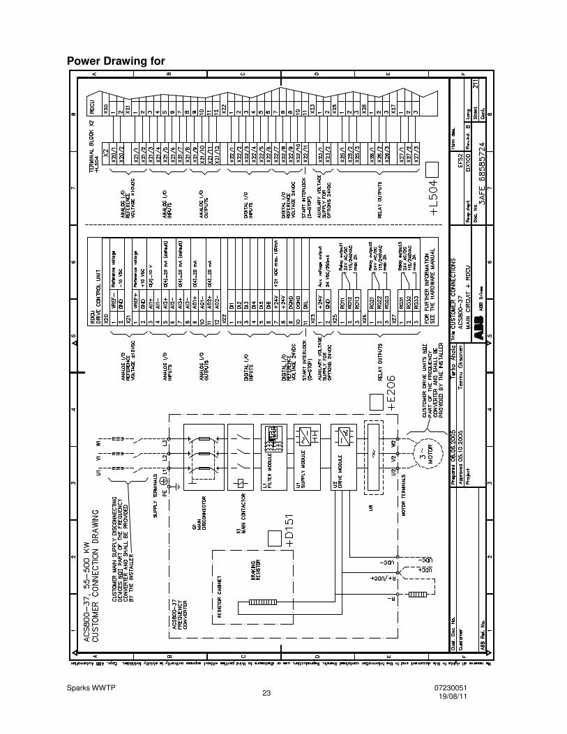
Power Drawing for
~
Sparks WWTP 07230051 19/08/11 24
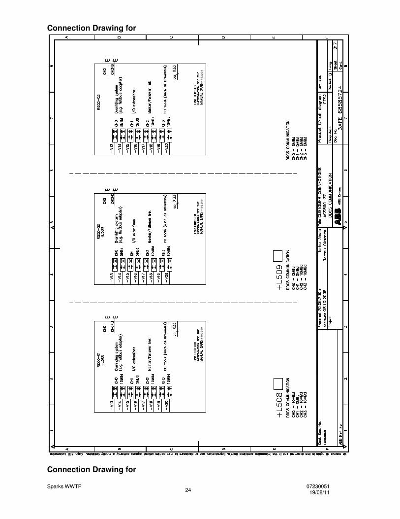
Connection Drawing for
64
49
22
09
64
49
22
09
64
49
22
09
Connection Drawing for
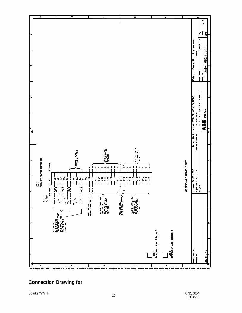
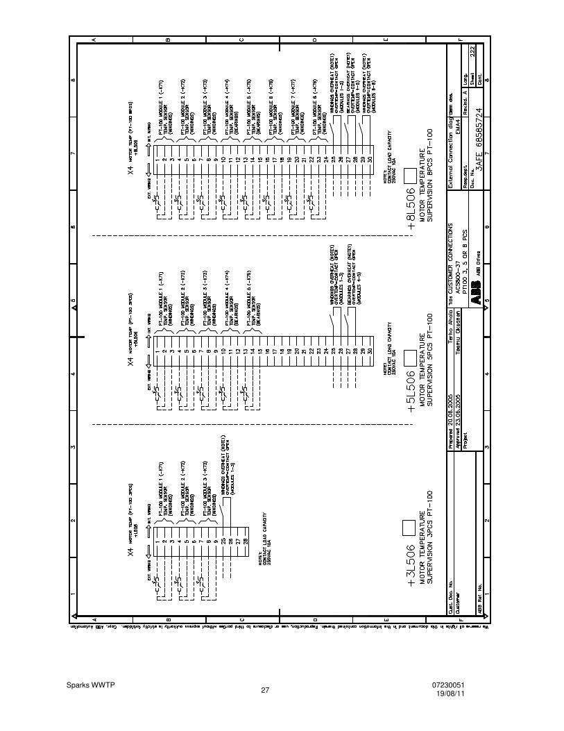
Sparks WWTP 07230051 19/08/11 25
Connection Drawing for
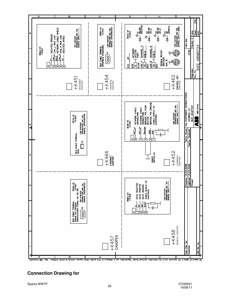
Sparks WWTP 07230051 19/08/11 26
MO
DB
US
A
DA
PT
ER
LON
WO
RK
S
AD
AP
TE
R
64
49
88
51
64
79
86
93
A
DA
PT
ER
64
50
PR
OF
IBU
S
AD
AP
TE
R
DE
VIC
EN
ET
A
DA
PT
ER
64
50
42
23
Connection Drawing for
Sparks WWTP 07230051 19/08/11 27
Sparks WWTP 07230051 19/08/11 28
Engineering Data and Ratings Tables
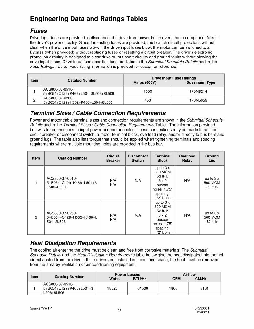
Fuses Drive input fuses are provided to disconnect the drive from power in the event that a component fails in the drive’s power circuitry. Since fast-acting fuses are provided, the branch circuit protections will not clear when the drive input fuses blow. If the drive input fuses blow, the motor can be switched to a Bypass (when provided) without replacing fuses or resetting a circuit breaker. The drive’s electronic protection circuitry is designed to clear drive output short circuits and ground faults without blowing the drive input fuses. Drive input fuse specifications are listed in the Submittal Schedule Details and in the Fuse Ratings Table. Fuse rating information is provided for customer reference.
Item Catalog Number Drive Input Fuse Ratings Amps (600V) Bussmann Type
1 ACS800-37-0510-5+B054+C129+K466+L504+3L506+8L506 1000 170M6214
2 ACS800-37-0260-5+B054+C129+H352+K466+L504+8L506 450 170M5059
Terminal Sizes / Cable Connection Requirements Power and motor cable terminal sizes and connection requirements are shown in the Submittal Schedule Details and in the Terminal Sizes / Cable Connection Requirements Table. The information provided below is for connections to input power and motor cables. These connections may be made to an input circuit breaker or disconnect switch, a motor terminal block, overload relay, and/or directly to bus bars and ground lugs. The table also lists torque that should be applied when tightening terminals and spacing requirements where multiple mounting holes are provided in the bus bar.
Item Catalog Number Circuit Breaker
Disconnect Switch
Terminal Block
Overload Relay
Ground Lug
1 ACS800-37-0510-5+B054+C129+K466+L504+3L506+8L506
N/A N/A
N/A
up to 3 x 500 MCM
52 ft-lb 3 x 2
busbar holes, 1.75"
spacing, 1/2" bolts
N/A
up to 3 x 500 MCM
52 ft-lb
2 ACS800-37-0260-5+B054+C129+H352+K466+L504+8L506
N/A N/A
N/A
up to 3 x 500 MCM
52 ft-lb 3 x 2
busbar holes, 1.75"
spacing, 1/2" bolts
N/A
up to 3 x 500 MCM
52 ft-lb
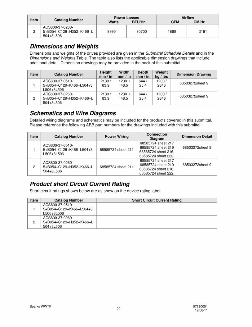
Heat Dissipation Requirements The cooling air entering the drive must be clean and free from corrosive materials. The Submittal Schedule Details and the Heat Dissipation Requirements table below give the heat dissipated into the hot air exhausted from the drives. If the drives are installed in a confined space, the heat must be removed from the area by ventilation or air conditioning equipment.
Item Catalog Number Power Losses Watts BTU/Hr
Airflow CFM CM/Hr
1 ACS800-37-0510-5+B054+C129+K466+L504+3L506+8L506
18020 61500 1860 3161
Sparks WWTP 07230051 19/08/11 29
Item Catalog Number Power Losses Watts BTU/Hr
Airflow CFM CM/Hr
2 ACS800-37-0260-5+B054+C129+H352+K466+L504+8L506
8995 30700 1860 3161
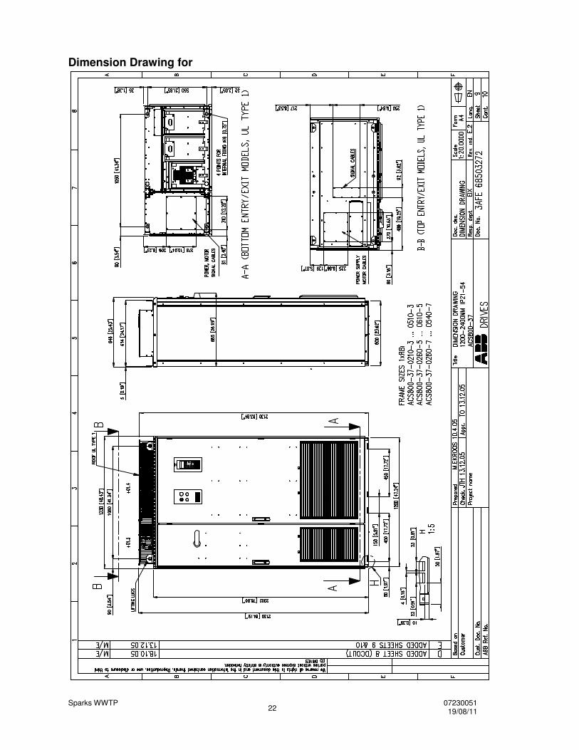
Dimensions and Weights Dimensions and weights of the drives provided are given in the Submittal Schedule Details and in the Dimensions and Weights Table. The table also lists the applicable dimension drawings that include additional detail. Dimension drawings may be provided in the back of this submittal.
Item Catalog Number Height mm / in
Width mm / in
Depth mm / in
Weight kg / lbs Dimension Drawing
1 ACS800-37-0510-5+B054+C129+K466+L504+3L506+8L506
2130 / 83.9
1230 / 48.5
644 / 25.4
1200 / 2646 68503272sheet 9
2 ACS800-37-0260-5+B054+C129+H352+K466+L504+8L506
2130 / 83.9
1230 / 48.5
644 / 25.4
1200 / 2646 68503272sheet 9
Schematics and Wire Diagrams Detailed wiring diagrams and schematics may be included for the products covered in this submittal. Please reference the following ABB part numbers for the drawings included with this submittal:
Item Catalog Number Power Wiring Connection Diagram Dimension Detail
1 ACS800-37-0510-5+B054+C129+K466+L504+3L506+8L506
68585724 sheet 211
68585724 sheet 217 68585724 sheet 219 68585724 sheet 216, 68585724 sheet 222,
68503272sheet 9
2 ACS800-37-0260-5+B054+C129+H352+K466+L504+8L506
68585724 sheet 211
68585724 sheet 217 68585724 sheet 219 68585724 sheet 216, 68585724 sheet 222,
68503272sheet 9
Product short Circuit Current Rating Short circuit ratings shown below are as show on the device rating label. Item Catalog Number Short Circuit Current Rating
1 ACS800-37-0510-5+B054+C129+K466+L504+3L506+8L506
2 ACS800-37-0260-5+B054+C129+H352+K466+L504+8L506