Embed Size (px)
Citation preview
The 0RQB-C2Q12x is an isolated dc/dc converter that operates
from a nominal 24 VDC source. This unit will provide up to 156 W
of output power from a nominal 24 VDC input.
This unit is designed to be highly efficient and low cost. Features
include remote on/off, over current protection and overvoltage
protection.
The converter is provided in an industry standard quarter brick
package.
• 9-36 VDC Input
• 12 VDC @ 13 A Output
• 1/4th Brick Converter
• Fixed Frequency
• High Efficiency
• High Power Density
• Low cost
• Input Under Voltage Lockout
• Input over voltage lockout
• OCP/SCP
• Output Over-voltage Protection
• Over Temperature Protection
• Remote On/Off
• Baseplate
• Basic Isolation
• Approved to UL/CSA 60950-1, 2nd +A2 version(TBD)
• Class II, Category 2, Isolated DC/DC Converter (refer to IPC-9592B)
• Networking
• Computers and peripherals
• Telecommunications
2 0RQB-C2Q12x
MODEL
NUMBER
OUTPUT
VOLTAGE
INPUT
VOLTAGE
MAX. OUTPUT
CURRENT
MAX. OUTPUT
POWER TYPICAL EFFICIENCY
0RQB-C2Q120 12 VDC 9-36 VDC 13A 156 W 94%
0RQB-C2Q12L 12 VDC 9-36 VDC 13A 156 W 94%
NOTE: Add “G” suffix at the end of the model number to indicate Tray Packaging.
0 R QB - C2 Q 12 x y
Mounting Type RoHS
Status
Series
Name
Output
Power
Input
Range
Output
Voltage Active Logic Package Type
Through hole mount RoHS 1/4th Brick 156 W 9-36V 12 V
L – active low,
without HSK
0 – active High ,
without HSK
G – Tray package
PARAMETER DESCRIPTION MIN TYP MAX UNITS
Continuous non-operating Input Voltage -0.3 - 36 V
Input Transient Voltage 100ms maximum - - 50 V
Input withstand Voltage 1min maximum, the module may turn off, but
will survive without damage. - - 48 V
Remote On/Off -0.3 - 18 V
I/O isolation voltage - - 1500 V
Ambient temperature -40 - 85 C
Storage Temperature -55 - 125 C
Relative humidity range 10 - 90 %
Altitude - - 2000 m
NOTE: Ratings used beyond the maximum ratings may cause a reliability degradation of the converter or may permanently damage the device.
PARAMETER DESCRIPTION MIN TYP MAX UNIT
Operating Input Voltage 9 24 36 V
Input Current (full load) Test at 9V input voltage - - 20.0 A
Input Current (no load) - 200 240 mA
Remote Off Input Current - 25 35 mA
Input Reflected Ripple Current (rms) With simulated source impedance of 10µ H,
5Hz to 20MHz. Use a 2*220µ F/100V
electrolytic capacitor with ESR=1 ohm max, at
200KHz@25°C.
- 5 10 mA
Input Reflected Ripple Current (pk-pk) - 30 40 mA
I2t Inrush Current Transient - 0.05 0.1 A2s
Turn-on Voltage Threshold 9.5 10 10.5 V
Turn-off Voltage Threshold 7.5 8 8.5 V
OTHER INFORMATION:
Input capacitance 4*4.7µ F/50V ceramic capacitor 18.8 µ F
NOTE: All specifications are typical at 25°C unless otherwise stated
CAUTION: This converter is not internally fused. An input line fuse must be used in application. Recommend a input fast-acting fuse with
Typical of 30A on system board. Refer to the fuse manufacture’s datasheet for further information.
0RQB-C2Q12x 3
Asia-Pacific
+86 755 298 85888 Europe, Middle East
+353 61 225 977 North America
+1 408 785 5200
© 2017 Bel Power Solutions & Protection Rev. AF
All specifications are typical at nominal input, full load at 25°C unless otherwise stated.
PARAMETER DESCRIPTION MIN TYP MAX UNIT
Output Voltage Set Point Vin=24 V, Io=50% load at 25˚C ambient. 11.8 12.04 12.28 V
Load Regulation Vin=24V, Io=0~100% load at 25˚C ambient. - ± 15 ± 30 mV
Line Regulation - ± 15 ± 30 mV
Regulation Over Temperature - ± 100 ± 200 mV
Output Ripple and Noise(Pk-Pk) Vin=24V ,Full load ,0-20MHz BW, with a 1µ F
ceramic capacitor and a 10µ F Tantalum cap
and 220µ F Tantalum cap at output.
- 100 150 mV
Output Ripple and Noise(RMS) - 25 40 mV
Output Current Range The 0RQB-C2Q12x module can start up with
17A for 100ms at Vin>12V. 0 - 13 A
Output DC Current Limit 15 20 25 A
Short Circuit Surge Transient - - 5 A2s
Rise time - 12 20 ms
Turn on Time Ton(Enable form Vin) - 30 40 ms
Ton(Enable form ON/OFF) - 30 40 ms
Overshoot at Turn on 0 - 3 %
Output Capacitance
Note: The minimum output
capacitance(220µ F) must be low ESR
capacitance, such as Tantalum capacitance
or POSCAP, and the total ESR must bigger
than 3mΩ .
220 - 5000 µ F
Transient Response
△V 50%~75% of Max Load
di/dt=0.1A/µ s, Vin=24VDC, Ta=25°C, with a
1µ F ceramic capacitor, a 10µ F Tantalum cap
and 220µ F Tantalum cap at output.
- 400 500 mV
Settling Time - 200 300 µ s
△V 75%~50% of Max Load - 400 500 mV
Settling Time - 200 300 µ s
NOTE: All specifications are typical at nominal input, full load at 25°C unless otherwise stated.
4 0RQB-C2Q12x
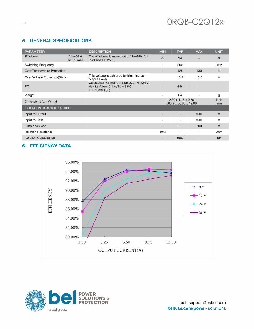
PARAMETER DESCRIPTION MIN TYP MAX UNIT
Efficiency Vin=24 V
Io=Io, max
The efficiency is measured at Vin=24V, full
load and Ta=25°C. 92 94 - %
Switching Frequency - 200 - kHz
Over Temperature Protection - 125 130 ℃
Over Voltage Protection(Static) This voltage is achieved by trimming up
output slowly. 15.3 15.8 V
FIT
Calculated Per Bell Core SR-332 (Vin=24 V,
Vo=12 V, Io=10.4 A, Ta = 58C,
FIT=109/MTBF)
- 546 - -
Weight - 64 - g
Dimensions (L × W × H) 2.30 x 1.45 x 0.50
58.42 x 36.83 x 12.68
inch
mm
ISOLATION CHARACTERISTICS
Input to Output - - 1500 V
Input to Case - - 1500 V
Output to Case - - 500 V
Isolation Resistance 10M - - Ohm
Isolation Capacitance - 3900 - pF
80.00%
82.00%
84.00%
86.00%
88.00%
90.00%
92.00%
94.00%
96.00%
1.30 3.25 6.50 9.75 13.00
EF
FIC
IEN
CY
OUTPUT CURRENT(A)
9 V
12 V
24 V
36 V
0RQB-C2Q12x 5
Asia-Pacific
+86 755 298 85888 Europe, Middle East
+353 61 225 977 North America
+1 408 785 5200
© 2017 Bel Power Solutions & Protection Rev. AF
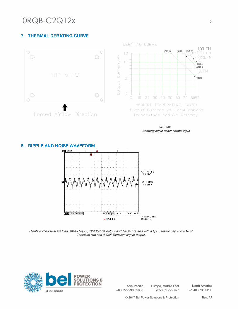
Vin=24V Derating curve under normal input
Ripple and noise at full load, 24VDC input, 12VDC/13A output and Ta=25 ˚ C, and with a 1µ F ceramic cap and a 10 uF
Tantalum cap and 220µ F Tantalum cap at output.
6 0RQB-C2Q12x
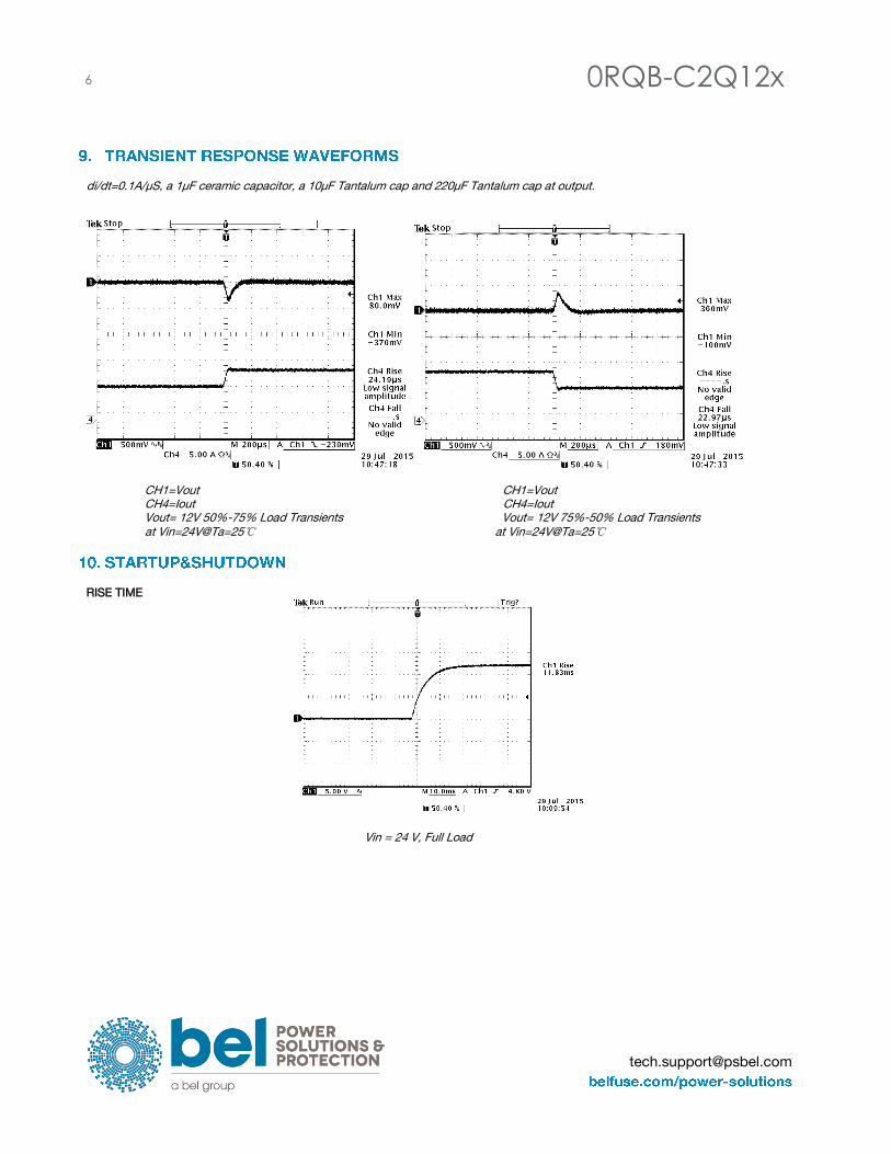
di/dt=0.1A/µ S, a 1µ F ceramic capacitor, a 10µ F Tantalum cap and 220µ F Tantalum cap at output.
CH1=Vout CH1=Vout CH4=Iout CH4=Iout Vout= 12V 50%-75% Load Transients Vout= 12V 75%-50% Load Transients
at Vin=24V@Ta=25℃ at Vin=24V@Ta=25℃
RISE TIME
Vin = 24 V, Full Load
0RQB-C2Q12x 7
Asia-Pacific
+86 755 298 85888 Europe, Middle East
+353 61 225 977 North America
+1 408 785 5200
© 2017 Bel Power Solutions & Protection Rev. AF
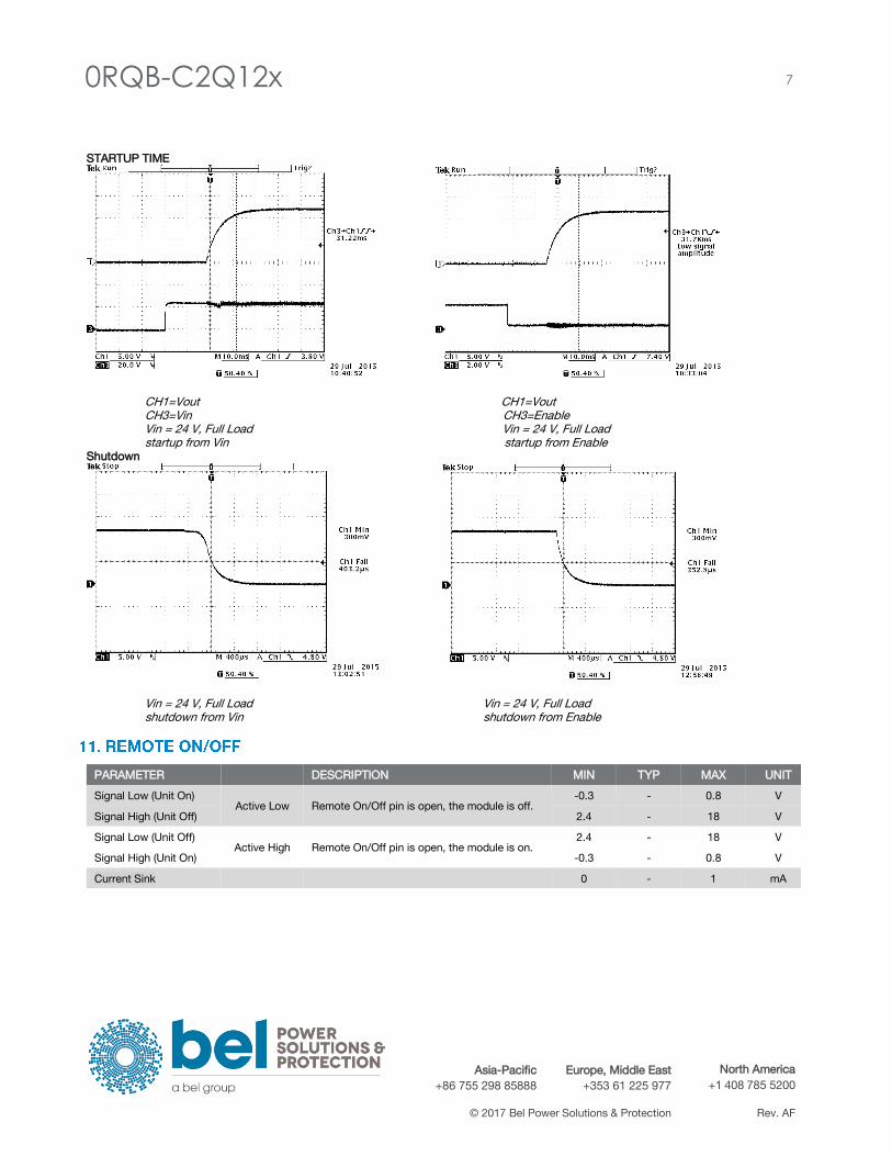
STARTUP TIME
CH1=Vout CH1=Vout CH3=Vin CH3=Enable Vin = 24 V, Full Load Vin = 24 V, Full Load startup from Vin startup from Enable
Shutdown
Vin = 24 V, Full Load Vin = 24 V, Full Load shutdown from Vin shutdown from Enable
PARAMETER DESCRIPTION MIN TYP MAX UNIT
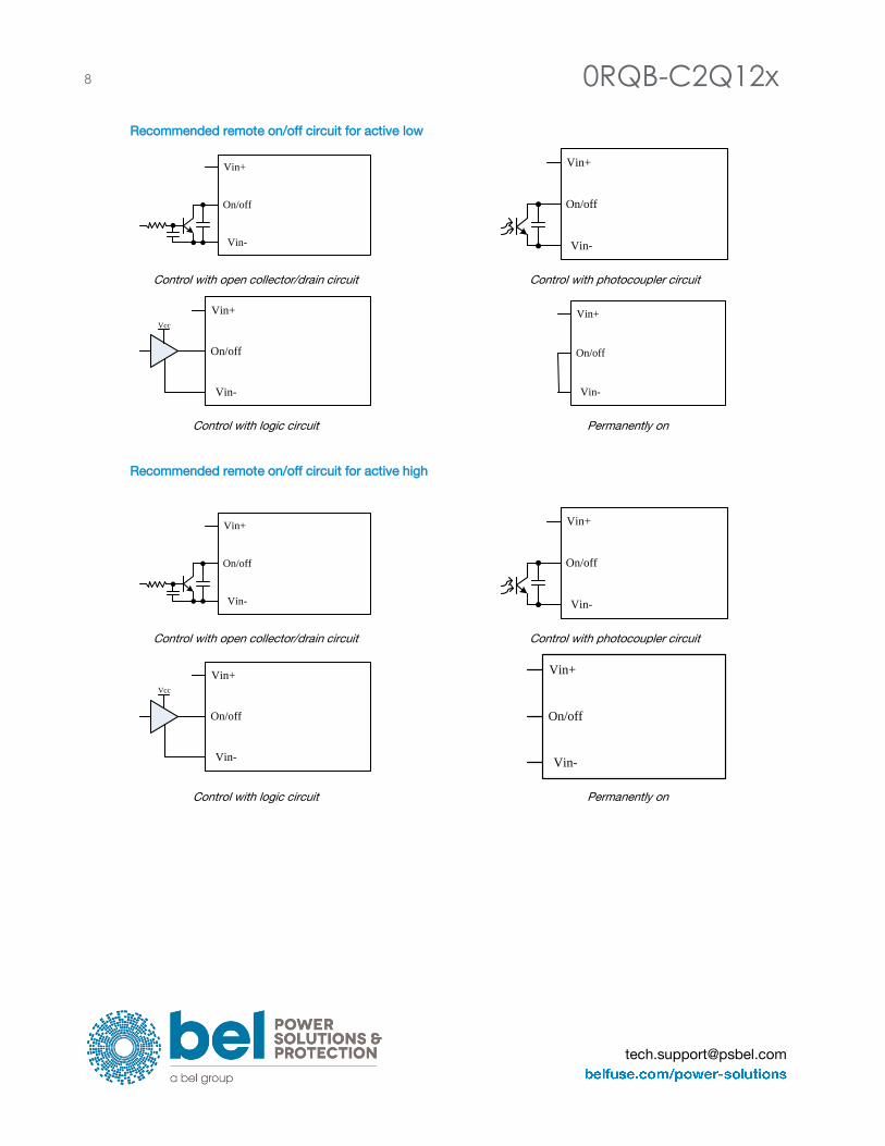
Signal Low (Unit On) Active Low Remote On/Off pin is open, the module is off.
-0.3 - 0.8 V
Signal High (Unit Off) 2.4 - 18 V
Signal Low (Unit Off) Active High Remote On/Off pin is open, the module is on.
2.4 - 18 V
Signal High (Unit On) -0.3 - 0.8 V
Current Sink 0 - 1 mA
8 0RQB-C2Q12x
Recommended remote on/off circuit for active low
Control with open collector/drain circuit Control with photocoupler circuit
Control with logic circuit Permanently on
Recommended remote on/off circuit for active high
Control with open collector/drain circuit Control with photocoupler circuit
Control with logic circuit Permanently on
Vin+
Vin-
On/off
Vin+
Vin-
On/off
Vin+
Vin-
On/off
Vcc
Vin+
Vin-
On/off
Vin+
Vin-
On/off
Vin+
Vin-
On/off
Vcc
Vin+
Vin-
On/off
Vin+
Vin-
On/off
0RQB-C2Q12x 9
Asia-Pacific
+86 755 298 85888 Europe, Middle East
+353 61 225 977 North America
+1 408 785 5200
© 2017 Bel Power Solutions & Protection Rev. AF
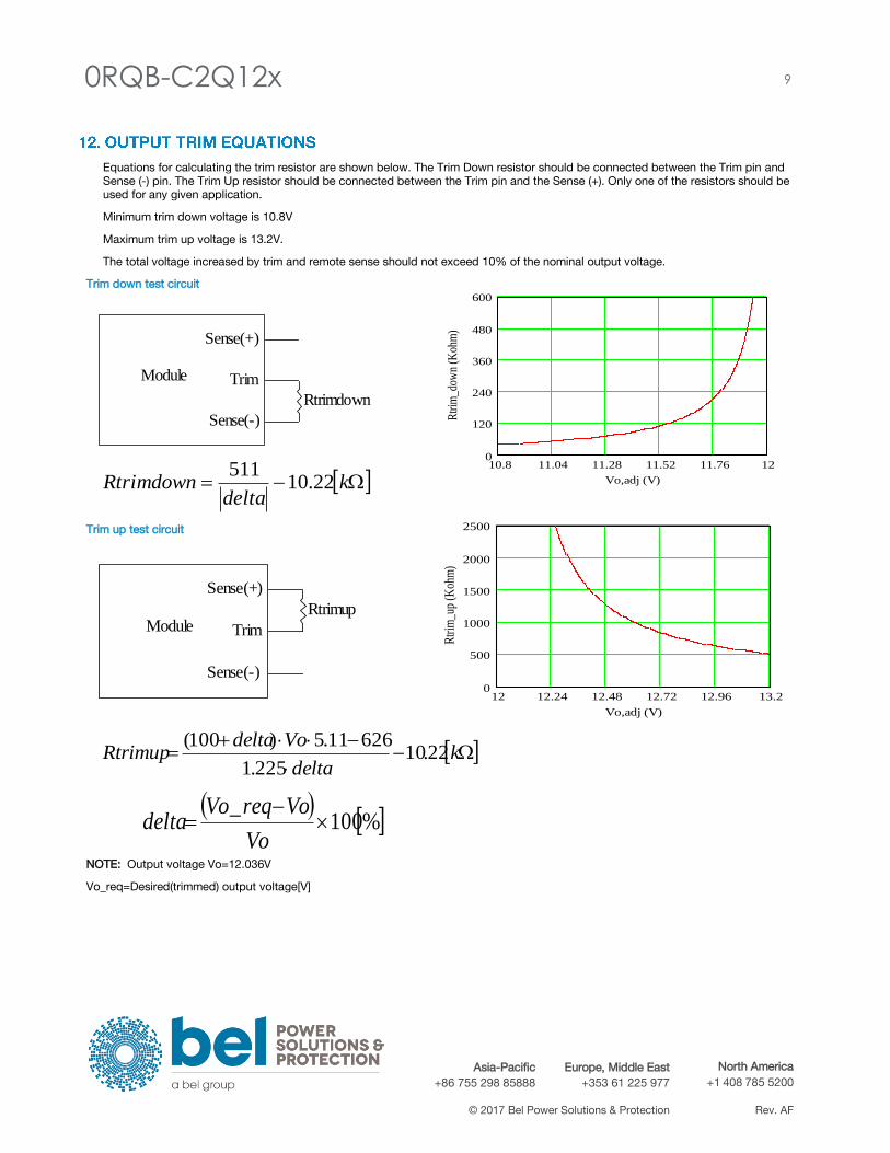
Equations for calculating the trim resistor are shown below. The Trim Down resistor should be connected between the Trim pin and
Sense (-) pin. The Trim Up resistor should be connected between the Trim pin and the Sense (+). Only one of the resistors should be
used for any given application.
Minimum trim down voltage is 10.8V
Maximum trim up voltage is 13.2V.
The total voltage increased by trim and remote sense should not exceed 10% of the nominal output voltage.
Trim down test circuit
Trim up test circuit
NOTE: Output voltage Vo=12.036V
Vo_req=Desired(trimmed) output voltage[V]
kdelta
Rtrimdown 22.10511
Module
Sense(+)
Trim
Sense(-)
Rtrimdown
10.8 11.04 11.28 11.52 11.76 120
120
240
360
480
600
Vo,adj (V)
Rtr
im_d
own
(Koh
m)
Module
Sense(+)
Trim
Sense(-)
Rtrimup
12 12.24 12.48 12.72 12.96 13.20
500
1000
1500
2000
2500
Vo,adj (V)
Rtr
im_u
p (K
ohm
)
k
delta
VodeltaRtrimup 22.10
225.1
62611.5)100(
%100
_
Vo
VoreqVodelta
10 0RQB-C2Q12x
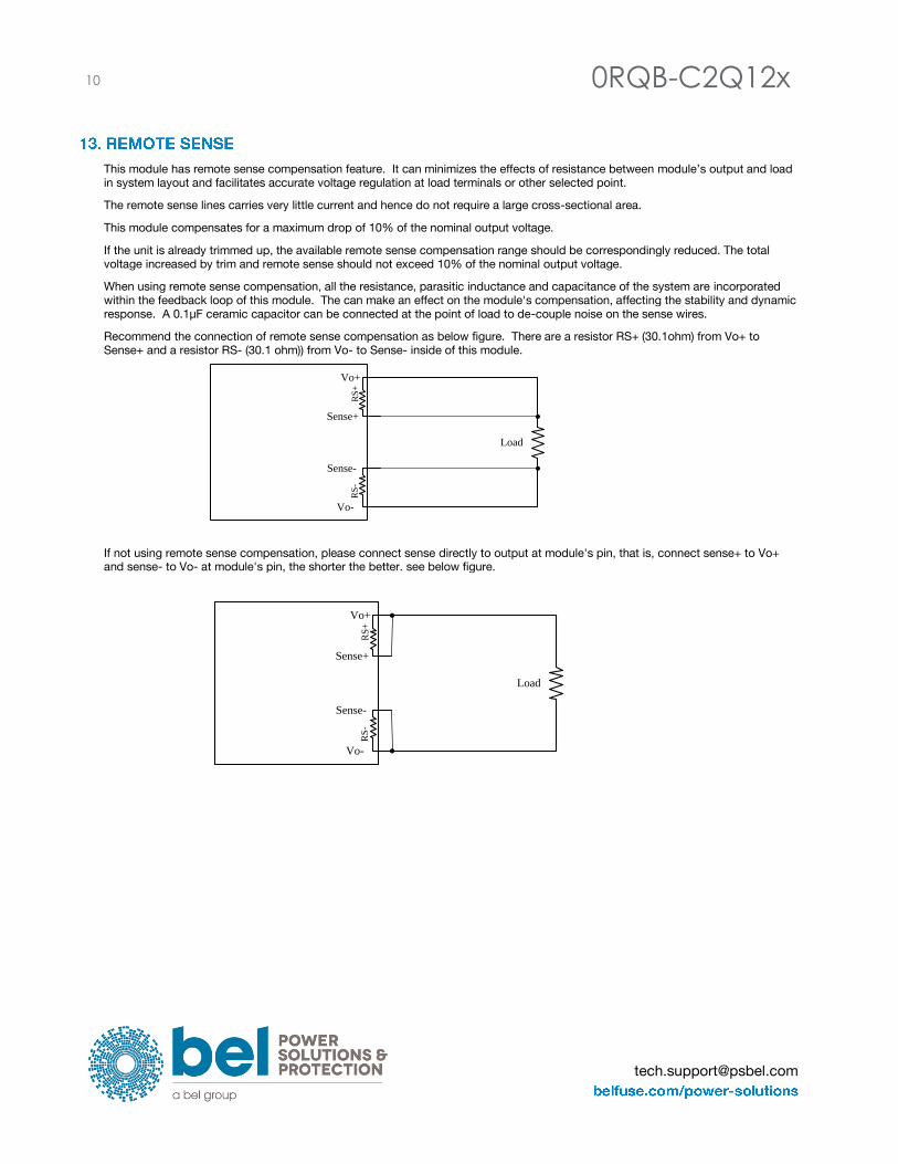
This module has remote sense compensation feature. It can minimizes the effects of resistance between module’s output and load
in system layout and facilitates accurate voltage regulation at load terminals or other selected point.
The remote sense lines carries very little current and hence do not require a large cross-sectional area.
This module compensates for a maximum drop of 10% of the nominal output voltage.
If the unit is already trimmed up, the available remote sense compensation range should be correspondingly reduced. The total
voltage increased by trim and remote sense should not exceed 10% of the nominal output voltage.
When using remote sense compensation, all the resistance, parasitic inductance and capacitance of the system are incorporated
within the feedback loop of this module. The can make an effect on the module's compensation, affecting the stability and dynamic
response. A 0.1µ F ceramic capacitor can be connected at the point of load to de-couple noise on the sense wires.
Recommend the connection of remote sense compensation as below figure. There are a resistor RS+ (30.1ohm) from Vo+ to
Sense+ and a resistor RS- (30.1 ohm)) from Vo- to Sense- inside of this module.
If not using remote sense compensation, please connect sense directly to output at module's pin, that is, connect sense+ to Vo+
and sense- to Vo- at module's pin, the shorter the better. see below figure.
Sense+
Sense-
RS
-
Vo-
Vo+
RS
+
Load
Sense+
Sense-
RS
-
Vo-
Vo+
RS
+
Load
0RQB-C2Q12x 11
Asia-Pacific
+86 755 298 85888 Europe, Middle East
+353 61 225 977 North America
+1 408 785 5200
© 2017 Bel Power Solutions & Protection Rev. AF
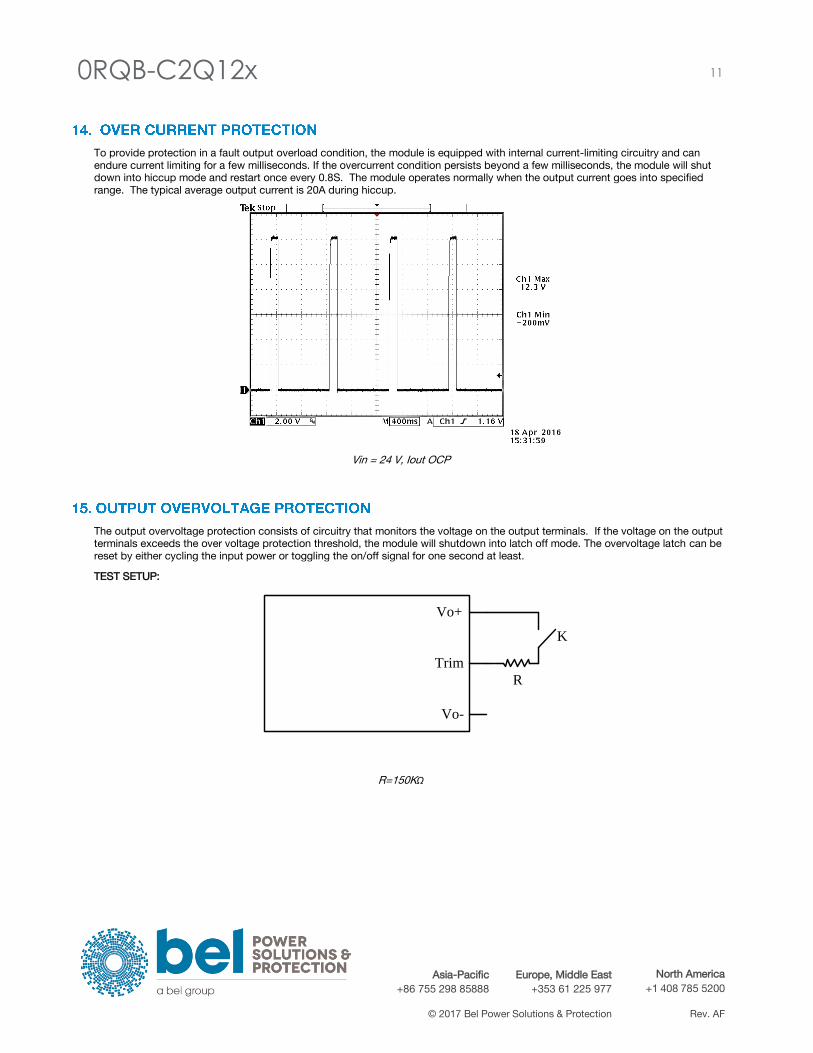
To provide protection in a fault output overload condition, the module is equipped with internal current-limiting circuitry and can
endure current limiting for a few milliseconds. If the overcurrent condition persists beyond a few milliseconds, the module will shut
down into hiccup mode and restart once every 0.8S. The module operates normally when the output current goes into specified
range. The typical average output current is 20A during hiccup.
Vin = 24 V, Iout OCP
The output overvoltage protection consists of circuitry that monitors the voltage on the output terminals. If the voltage on the output
terminals exceeds the over voltage protection threshold, the module will shutdown into latch off mode. The overvoltage latch can be
reset by either cycling the input power or toggling the on/off signal for one second at least.
TEST SETUP:
R=150KΩ
Vo+
Vo-
Trim
R
K
12 0RQB-C2Q12x
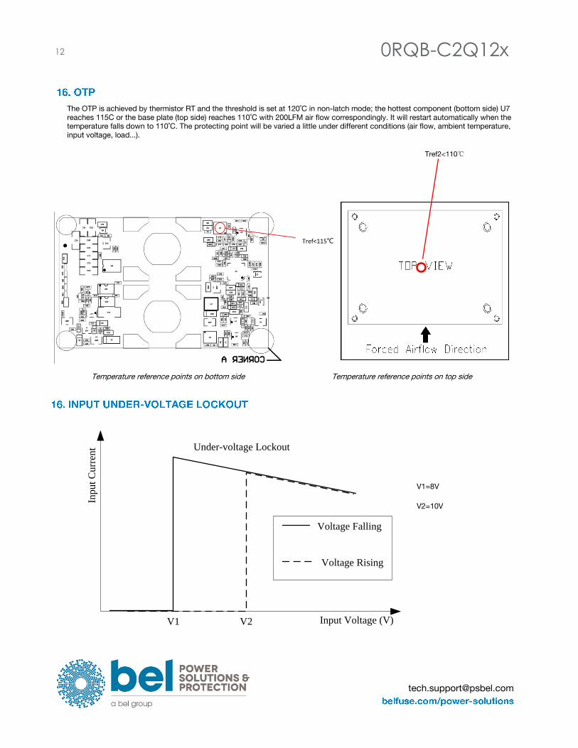
The OTP is achieved by thermistor RT and the threshold is set at 120˚C in non-latch mode; the hottest component (bottom side) U7
reaches 115C or the base plate (top side) reaches 110˚C with 200LFM air flow correspondingly. It will restart automatically when the
temperature falls down to 110˚C. The protecting point will be varied a little under different conditions (air flow, ambient temperature,
input voltage, load...).
Temperature reference points on bottom side Temperature reference points on top side
V1=8V
V2=10V
Input Voltage (V)
Inp
ut
Cu
rren
t
Voltage Falling
Voltage Rising
V1 V2
Under-voltage Lockout
Tref2<110℃
Tref<115℃
0RQB-C2Q12x 13
Asia-Pacific
+86 755 298 85888 Europe, Middle East
+353 61 225 977 North America
+1 408 785 5200
© 2017 Bel Power Solutions & Protection Rev. AF
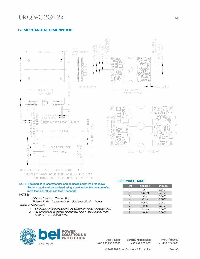
NOTE: This module is recommended and compatible with Pb-Free Wave
Soldering and must be soldered using a peak solder temperature of no
more than 260 ºC for less than 5 seconds.
NOTES: All Pins: Material - Copper Alloy;
Finish – 3 micro inches minimum Gold over 50 micro inches
minimum Nickel plate. 1) Undimensioned components are shown for visual reference only. 2) All dimensions in inches; Tolerances: x.xx +/-0.02 in [0.51 mm].
x.xxx +/-0.010 in [0.25 mm].
PIN FUNCTION PIN SIZE
1 Vin+ 0.040’’
2 On/Off 0.040’’
3 Vin- 0.040’’
4 Vout- 0.060’’
5 Sense- 0.040’’
6 Trim 0.040’’
7 Sense+ 0.040’’
8 Vout+ 0.060’’
14 0RQB-C2Q12x
SAFETY :
TBD
EMC:
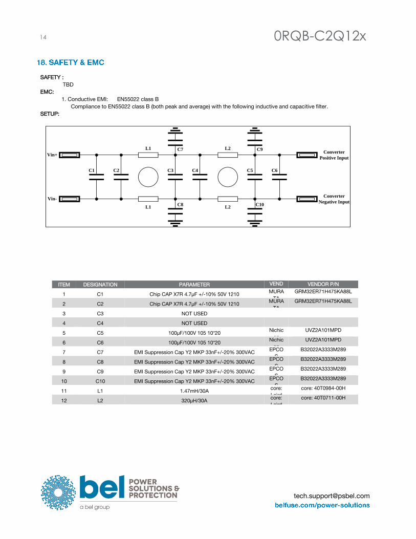
1. Conductive EMI: EN55022 class B
Compliance to EN55022 class B (both peak and average) with the following inductive and capacitive filter.
SETUP:
ITEM DESIGNATION PARAMETER VEND
OR
VENDOR P/N
1 C1 Chip CAP X7R 4.7µ F +/-10% 50V 1210 MURA
TA
GRM32ER71H475KA88L
2 C2 Chip CAP X7R 4.7µ F +/-10% 50V 1210 MURA
TA
GRM32ER71H475KA88L
3 C3 NOT USED
4 C4 NOT USED
5 C5 100µ F/100V 105 10*20 Nichic
on
UVZ2A101MPD
6 C6 100µ F/100V 105 10*20 Nichic
on
UVZ2A101MPD
7 C7 EMI Suppression Cap Y2 MKP 33nF+/-20% 300VAC EPCO
S
B32022A3333M289
8 C8 EMI Suppression Cap Y2 MKP 33nF+/-20% 300VAC EPCO
S
B32022A3333M289
9 C9 EMI Suppression Cap Y2 MKP 33nF+/-20% 300VAC EPCO
S
B32022A3333M289
10 C10 EMI Suppression Cap Y2 MKP 33nF+/-20% 300VAC EPCO
S
B32022A3333M289
11 L1 1.47mH/30A core:
Laird
core: 40T0984-00H
12 L2 320µ H/30A core:
Laird
core: 40T0711-00H
C1 C2 C3 C4
C7
C8
L1
L1
Vin+
Vin-
Converter
Positive Input
Converter
Negative Input
C5 C6
C9
C10
L2
L2
0RQB-C2Q12x 15
Asia-Pacific
+86 755 298 85888 Europe, Middle East
+353 61 225 977 North America
+1 408 785 5200
© 2017 Bel Power Solutions & Protection Rev. AF
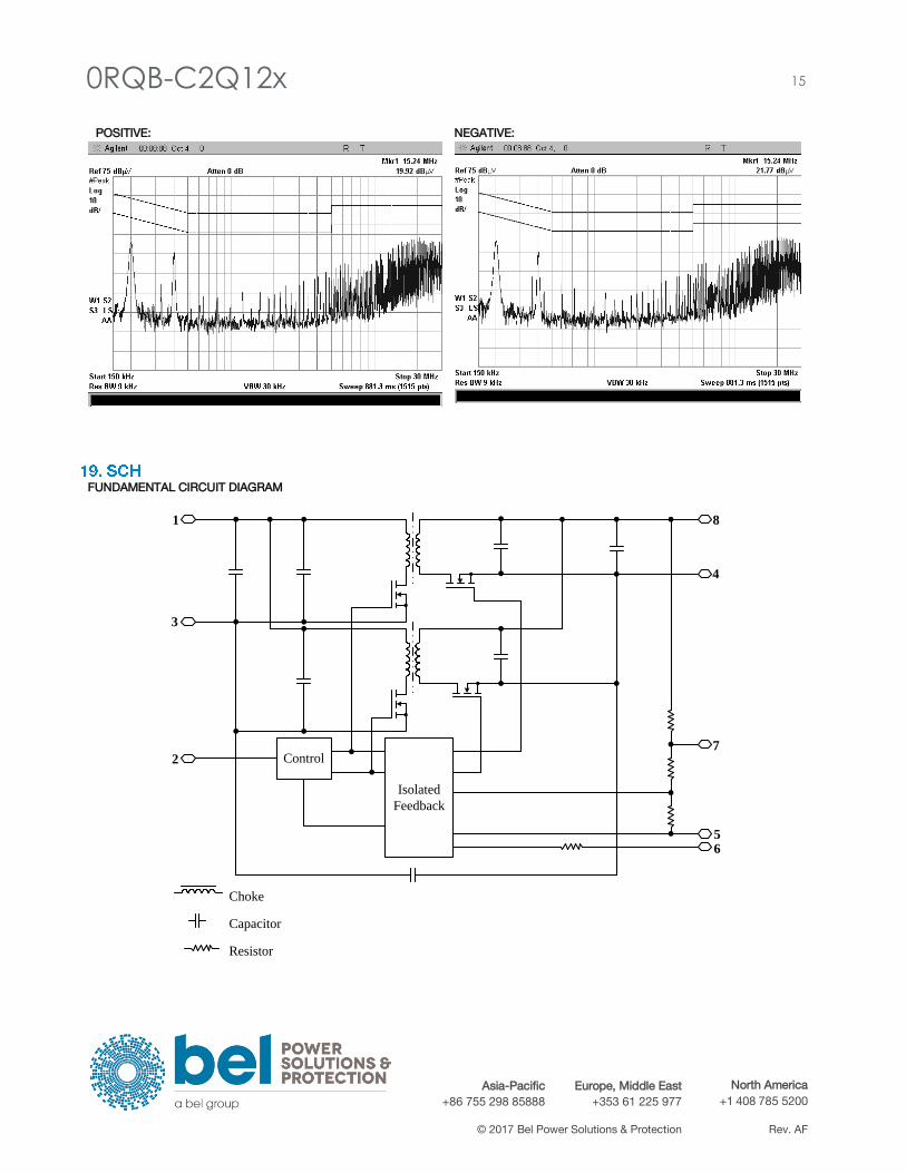
POSITIVE: NEGATIVE:
FUNDAMENTAL CIRCUIT DIAGRAM
Control
Isolated
Feedback
1
2
3
8
4
7
56
Choke
Capacitor
Resistor
16 0RQB-C2Q12x
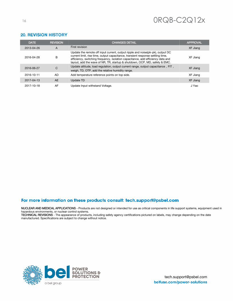
DATE REVISION CHANGES DETAIL APPROVAL
2013-04-26 A First revision XF Jiang
2016-04-28 B
Update the remote off input current, output ripple and noise(pk-pk), output DC
current limit, rise time, output capacitance, transient response settling time,
efficiency, switching frequency, isolation capacitance, add efficiency data and
layout, add the wave of NR, TR, startup & shutdown, OCP, MD, safety & EMC.
XF Jiang
2016-06-27 C Update altitude, load regulation, output current range, output capacitance,FIT,
weigh, TD, OTP, add the relative humidity range. XF Jiang
2016-10-11 AD Add temperature reference points on top side. XF Jiang
2017-04-13 AE Update TD XF Jiang
2017-10-18 AF Update Input withstand Voltage. J Yao
NUCLEAR AND MEDICAL APPLICATIONS - Products are not designed or intended for use as critical components in life support systems, equipment used in
hazardous environments, or nuclear control systems.
TECHNICAL REVISIONS - The appearance of products, including safety agency certifications pictured on labels, may change depending on the date
manufactured. Specifications are subject to change without notice.