Embed Size (px)
Citation preview
1
16-18/5/2001
GPM Planning Workship
Ka-band Radar for GPM:Issues
Toshio Iguchi
Communications Research Laboratory
The Global Precipitation Mission Planning WorkshopThe Global Precipitation Mission Planning Workshop
University of MarylandUniversity of Maryland
College Park, Maryland, U.S.A.College Park, Maryland, U.S.A.
2
GPM Planning Workship16-18/5/2001
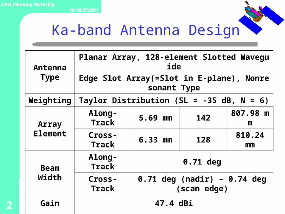
Ka-band Antenna Design
Antenna Type
Planar Array, 128-element Slotted Waveguide
Edge Slot Array(=Slot in E-plane), Nonresonant Type
Weighting Taylor Distribution (SL = -35 dB, N = 6)
Array Element
Along-Track 5.69 mm 142 807.98 mm
Cross-Track 6.33 mm 128 810.24 mm
Beam WidthAlong-Track 0.71 deg
Cross-Track 0.71 deg (nadir) – 0.74 deg (scan edge)
Gain 47.4 dBi
Sidelobe < -27 dB
VSWR < 1.2Waveguide
Loss0.71 dB
3
GPM Planning Workship16-18/5/2001
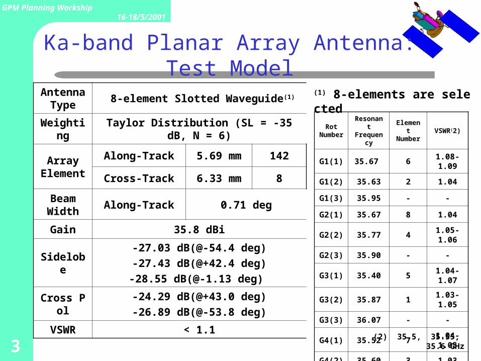
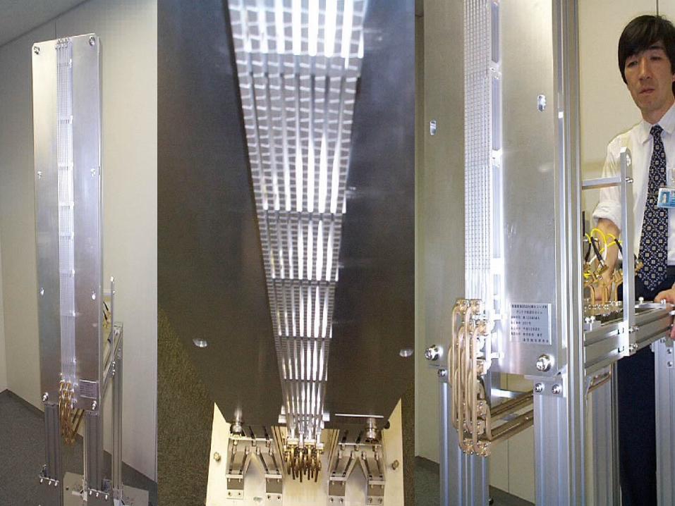
Ka-band Planar Array Antenna: Test Model
Rot Number
Resonant Frequency
Element Number
VSWR(2)
G1(1) 35.67 6 1.08-1.09
G1(2) 35.63 2 1.04
G1(3) 35.95 - -
G2(1) 35.67 8 1.04
G2(2) 35.77 4 1.05-1.06
G2(3) 35.90 - -
G3(1) 35.40 5 1.04-1.07
G3(2) 35.87 1 1.03-1.05
G3(3) 36.07 - -
G4(1) 35.52 7 1.04-1.05
G4(2) 35.60 3 1.03
G4(3) 35.67 - -
(2) 35.5, 35.55, 35.6 GHz
Antenna Type
8-element Slotted Waveguide(1)
Weighting Taylor Distribution (SL = -35 dB, N = 6)
Array Element
Along-Track 5.69 mm 142
Cross-Track 6.33 mm 8
Beam Width
Along-Track 0.71 deg
Gain 35.8 dBi
Sidelobe
-27.03 dB(@-54.4 deg)
-27.43 dB(@+42.4 deg)
-28.55 dB(@-1.13 deg)
Cross Pol-24.29 dB(@+43.0 deg)
-26.89 dB(@-53.8 deg)
VSWR < 1.1
(1) 8-elements are selected
4
GPM Planning Workship16-18/5/2001
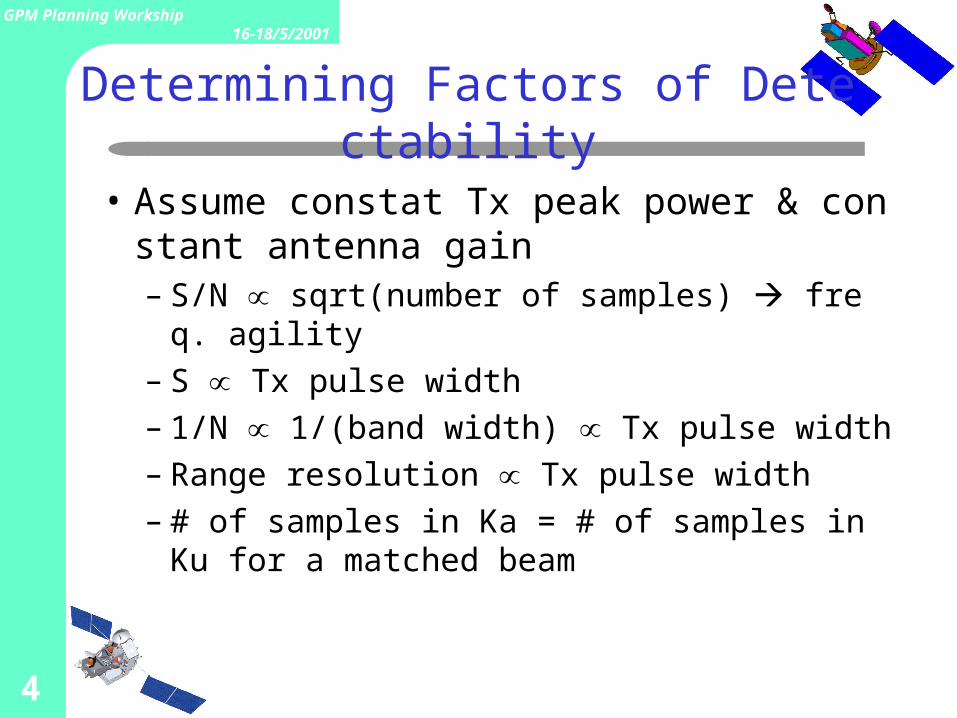
Determining Factors of Detectability
• Assume constat Tx peak power & constant antenna gain– S/N sqrt(number of samples) ∝ freq. agility– S Tx pulse width∝– 1/N 1/(band width) Tx pulse width∝ ∝– Range resolution Tx pulse width∝– # of samples in Ka = # of samples in Ku for a m
atched beam
5
GPM Planning Workship16-18/5/2001
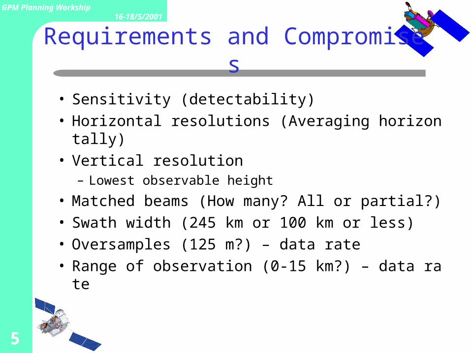
Requirements and Compromises
• Sensitivity (detectability)• Horizontal resolutions (Averaging horizontally)• Vertical resolution
– Lowest observable height
• Matched beams (How many? All or partial?)• Swath width (245 km or 100 km or less)• Oversamples (125 m?) – data rate• Range of observation (0-15 km?) – data rate
6
GPM Planning Workship16-18/5/2001
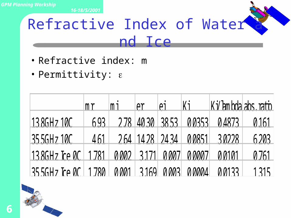
mr mi er ei Ki Ki/ lambda abs. ratio13.8GHz 10C 6.93 2.78 40.30 38.53 0.0353 0.4873 0.16135.5GHz 10C 4.61 2.64 14.28 24.34 0.0851 3.0228 6.20313.8GHz Ice 0C 1.781 0.002 3.171 0.007 0.0007 0.0101 0.76135.5GHz Ice 0C 1.780 0.001 3.169 0.003 0.0004 0.0133 1.315
Refractive Index of Water and Ice
• Refractive index: m
• Permittivity:
7
GPM Planning Workship16-18/5/2001
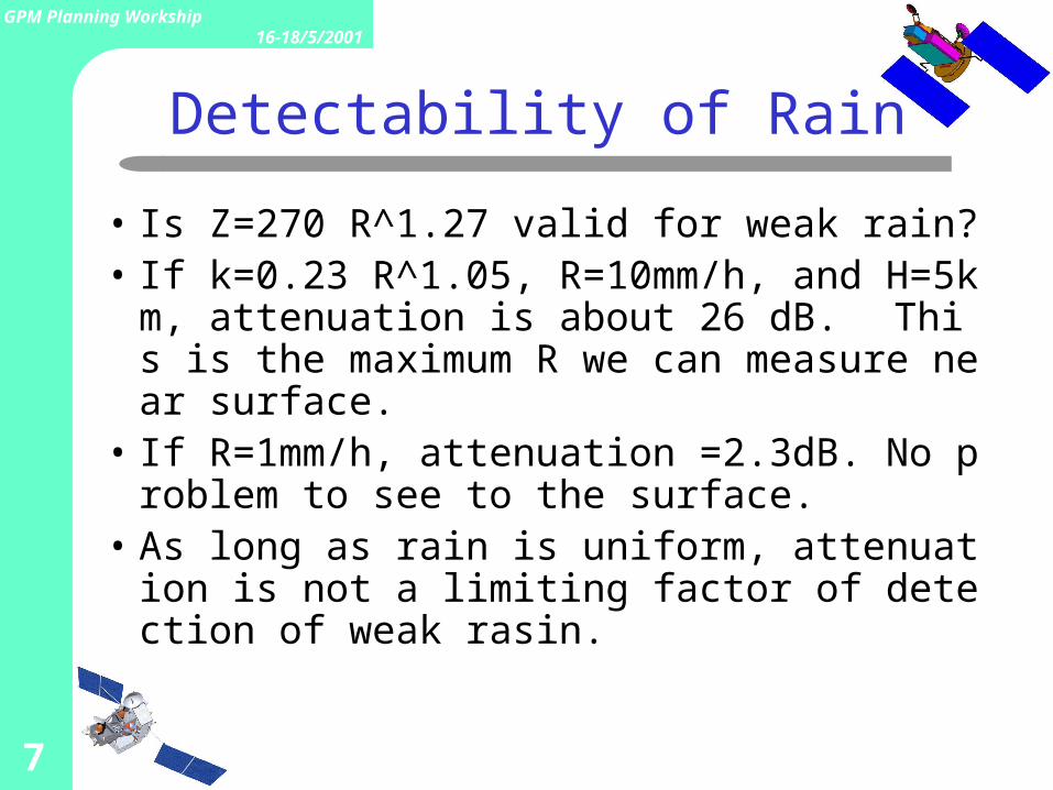
Detectability of Rain
• Is Z=270 R^1.27 valid for weak rain?• If k=0.23 R^1.05, R=10mm/h, and H=5km, a
ttenuation is about 26 dB. This is the maximum R we can measure near surface.
• If R=1mm/h, attenuation =2.3dB. No problem to see to the surface.
• As long as rain is uniform, attenuation is not a limiting factor of detection of weak rasin.
8
GPM Planning Workship16-18/5/2001
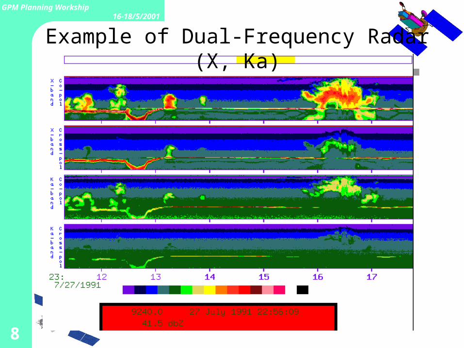
Example of Dual-Frequency Radar (X, Ka)
9
GPM Planning Workship16-18/5/2001
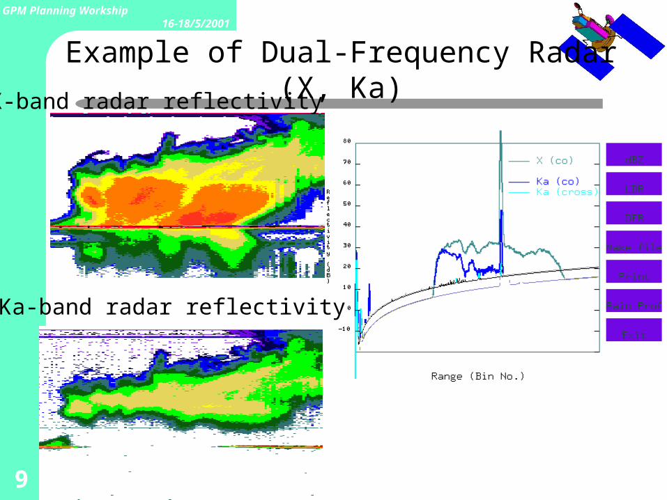
Example of Dual-Frequency Radar (X, Ka)X-band radar reflectivity
Ka-band radar reflectivity
10
GPM Planning Workship16-18/5/2001
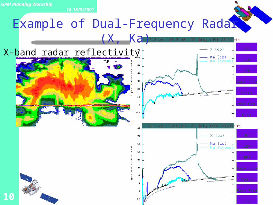
Example of Dual-Frequency Radar (X, Ka)
X-band radar reflectivity
11
GPM Planning Workship16-18/5/2001
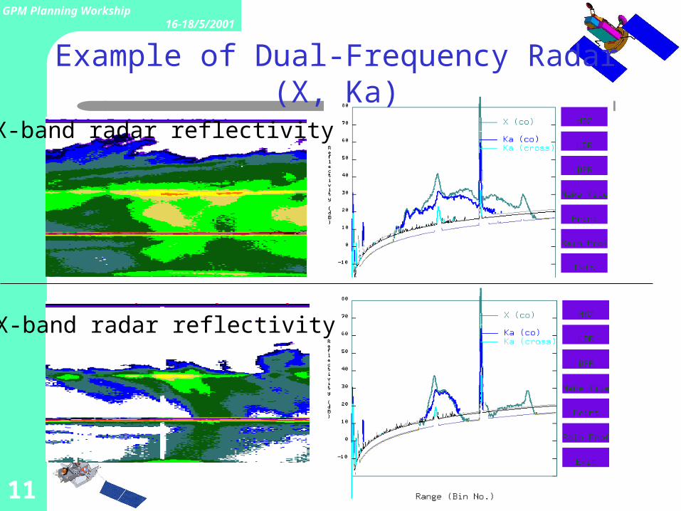
Example of Dual-Frequency Radar (X, Ka)
X-band radar reflectivity
X-band radar reflectivity
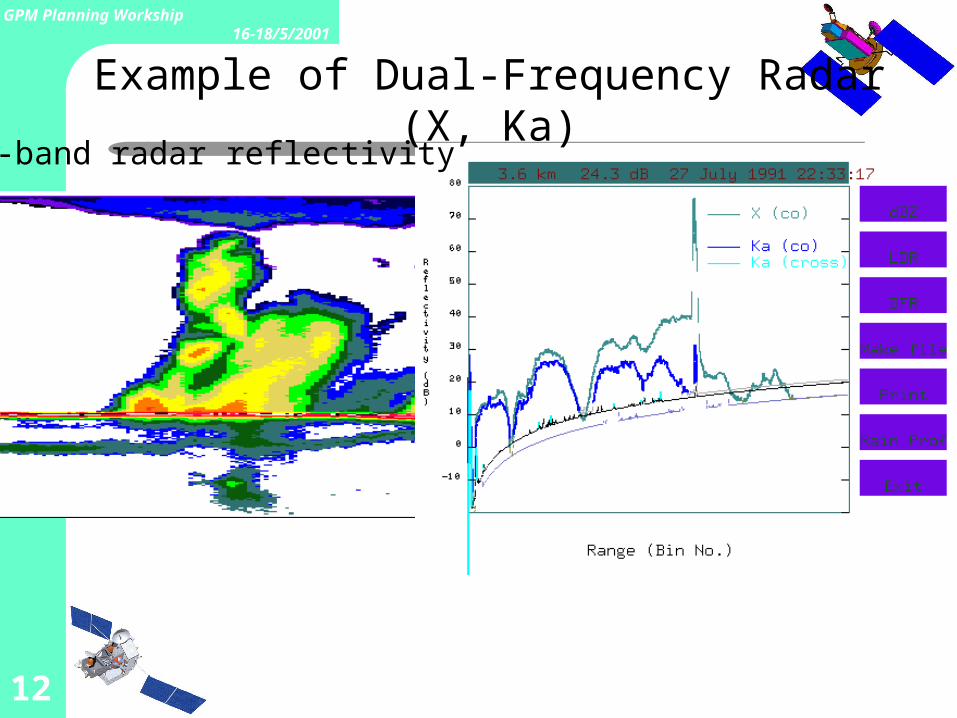
12
GPM Planning Workship16-18/5/2001
Example of Dual-Frequency Radar (X, Ka)X-band radar reflectivity
13
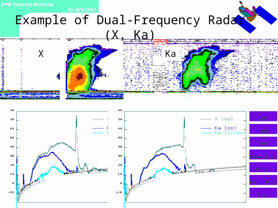
GPM Planning Workship16-18/5/2001
Example of Dual-Frequency Radar (X, Ka)
X Ka
14
GPM Planning Workship16-18/5/2001
15
GPM Planning Workship16-18/5/2001
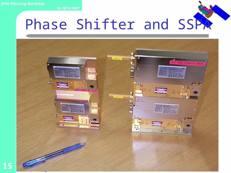
Phase Shifter and SSPA
16
GPM Planning Workship16-18/5/2001
What is the Ka-band radar for?• High sensitivity
– to measure weak rain and snow .• High precision
– Increase of information by the combination of two channels
• Attenaution and rain rate are nearly proportional at 35GHz.– Rain estimation independent of DSD.
• Separation of snow from rain.• Vertical structure microwave radiometer algorithm
• To what extent can we realize high sensitivity and high precision?– What kind of science can we do with DPR data?
17
GPM Planning Workship16-18/5/2001
Present Status of Ka-band Radar Design
• Phased Array System– Increase in power consumption and mass– Heat release– Pulse compression too risky
• Doppler broadening → range sidelobe• Increase in power consumption
– Matched beam realizable
• Sensitivity vs. swath width and vertical resolution• What are the scientific requirements?• Priority? (sensitivity, accuracy, resolution, swath)
18
GPM Planning Workship16-18/5/2001
Original Requirements
• Frequency = 35.5GHz• Sensitivity 11dBZ (S/N_e = 3 dB) or better• Resolutions 4 km (horizontal), 250 m (vert
ical)• Beams matched with Ku-band beams• Swath 20 ~ 40 km• Weight < 100 kg, Power < 100 W
19
GPM Planning Workship16-18/5/2001
PR Rain Retrieval Algorithm
• Attenuation correction essential– needs k-Ze relationship– utilizes the surface reference technique
• Conversion from Ze to R– Needs Ze-R relationship
• Both relationships depend on:– DSD – phase state– storm structure (non-uniform beam filling)
• Validation needed, but very difficult
20
GPM Planning Workship16-18/5/2001
Basic Design of Ka-band Radar
• Phased-Array system– Matched beams– No need for pulse compression– Flexibility in scanning
• Independent unit– Easy in test and inspection
21
GPM Planning Workship16-18/5/2001
CRL’s commitment Ka-band Radar Development (Designing and testing the
key components of the 35GHz radar) Examination of basic performance of hardware
Overall configuration Pulse compression (FY2000)
Designing of critical components and testing (FY2000) SSPA (2.5 W) Phase shifter (5 bits) Antenna (90 cm)
Examination of basic performance of hardware (FY2001) BBM
Evaluation of measurement performance (FY2000, 2001) Simulation Experiments
Dual-frequency algorithm development
22
GPM Planning Workship16-18/5/2001
Mass & Power Consumption
Total Mass: 290 kg Phased-array system is heavy Heat sink
Power consumption: 250 W Efficiency of SSPA is limited
Dimensions: 1.0 ×1.0 ×0.5 m
23
GPM Planning Workship16-18/5/2001
• DF algorithm is essential for DSD estimation and liquid-ice separation
• DF algorithm requires a matched beam– How well do two beams need matched?– Matched beam requirement restricts # of pulses
per beam for Ka-band
• Sensitivity or DF information?
Scientific Requirements
24
GPM Planning Workship16-18/5/2001
Separation of ice from rain(Differences in Ka & Ku echoes)
• Rain– Effective Z ( Ze) is nearly idential up to 2 mm/h– Attenuation (Ka) is about 10 times of attenuation (Ku)
• Detection of melting height• Snow (ice)
– Ze of snow is different from Ze of rain– Ze is nearly identical when particles are small– Ze is different when particles are large (hail)– Attenuation by absorption are negligible at both Ka, and Ku.
• At 35.5GHz, 1/22 of rain .• At 13.8GHz, 1/48 of rain .
– Difference in scattering by large ice particles (hail).• Difference in attenuation.• Difference in Ze.
– Can we distinguish hail from rain?• Interdependence of phase judgement and DSD estimation.
25
GPM Planning Workship16-18/5/2001
Non-Uniform Rain and Beam Matching
• DPR algorithm uses attenuation difference.• Non-uniform rain decreases apparent attenuation.
– underestimates rain rate.– overestimates large drops in DSD.
• Non-uniformity of rain and beam mismatching may overturn the basic assumptions in dual-frequency algorithms.– How well can we match beams?
• 0.2°(1400m) ?– Effects of beam mismatch?
• needs simulations.
26
GPM Planning Workship16-18/5/2001
Engineering Issues in Ka-band Radar Development
• Sensitivity– pulse compression– Vertical resolution (Is 500m res. acceptable?)
• Mass and power consumption (heat release)• Data rate
– Sampling interval• 125 m oversample?
– On-board processing• surface detection• data compression
– No. of bits for each echo datum (TRMM uses 8 bits, 0.38 dB res.)• Mount:
– interfarence with TMI’s field of view?– Accuracy of beam matching
27
GPM Planning Workship16-18/5/2001
Present Status of Ka-band Radar Studies for Atmos-A1
• Designing with a phased-array system– Increasing # of array elements increases total power consu
mption and mass – Mass and power consumption (heat release) are the issues
• Possibility of 500-m vertical resolution– To increase sensitivity by 6 dB– Almost no degradation of V resolution except near nadir– Power consumption and mass will increase
• Matched beam requirement• Trade-off between sensitivity and swath width
– Needs scientific compromise– Provides multiple observation modes? (Confusing?)
28
GPM Planning Workship16-18/5/2001
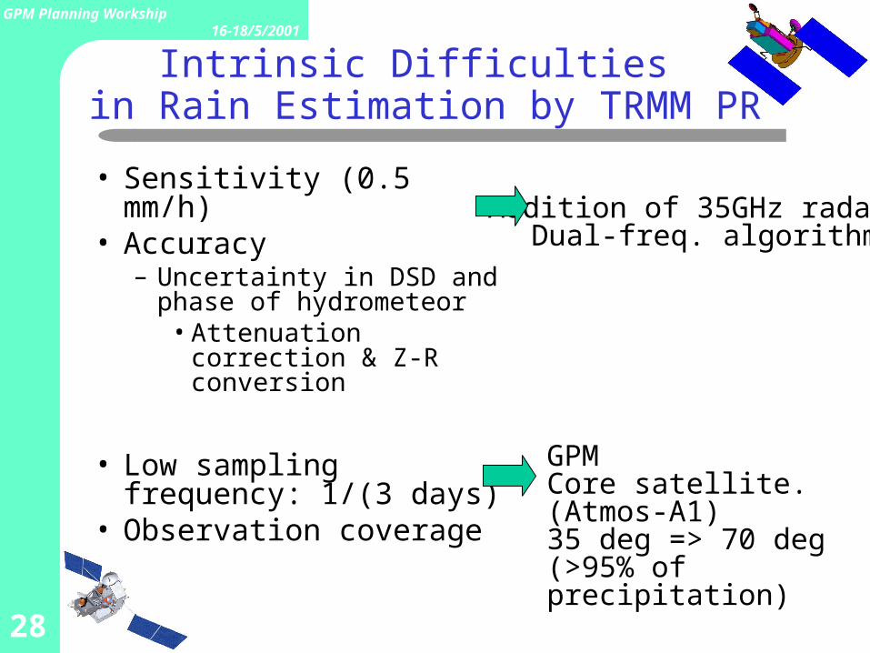
Intrinsic Difficulties in Rain Estimation by TRMM PR
• Sensitivity (0.5 mm/h)• Accuracy
– Uncertainty in DSD and phase of hydrometeor
• Attenuation correction & Z-R conversion
• Low sampling frequency: 1/(3 days)
• Observation coverage
GPMCore satellite. (Atmos-A1)35 deg => 70 deg (>95% of precipitation)
Addition of 35GHz radarDual-freq. algorithm
29
GPM Planning Workship16-18/5/2001
Issues
• Hardware Specifications– Mass
– Power Consumption
– Sensitivity
– Accuracy
• Science issues– Dual-Frequency Algorithm
– Combining DPR and TMI Information
30
GPM Planning Workship16-18/5/2001
Issues
• Sensitivity– Pulse compression– Vertical resolution (500 m acceptable?)
• Mass and power consumption (& heat release)
• Data rate– Sampling interval -- 125 m over sample (?)– On-board processing– Quantization of data
• Mount -- Interference with TMI field of view
31
GPM Planning Workship16-18/5/2001
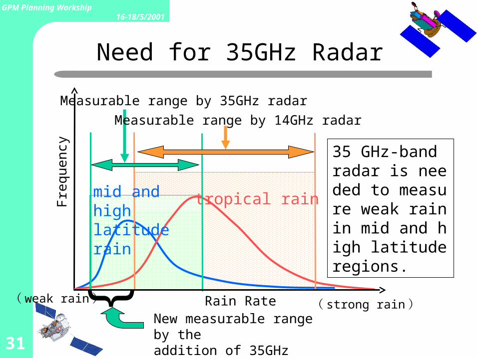
Fre
quen
cy
tropical rainmid and high latitude rain
}Rain Rate
Measurable range by 35GHz radar
Measurable range by 14GHz radar
35 GHz-band radar is needed to measure weak rain in mid and high latitude regions.
New measurable range by the addition of 35GHz radar
( strong rain)( weak rain)
Need for 35GHz Radar
32
GPM Planning Workship16-18/5/2001
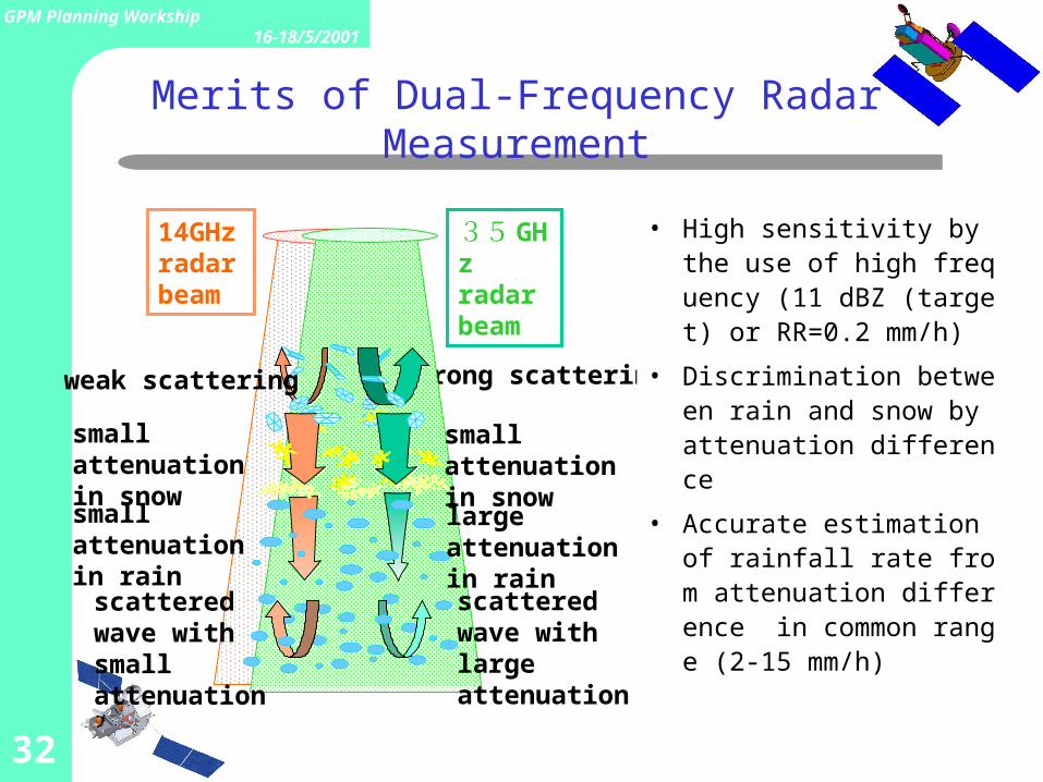
35 GHzradar beam
14GHzradar beam
strong scattering
small attenuation in snow
small attenuation in snow
small attenuation in rain
scattered wave with small attenuation
weak scattering
large attenuation in rain
scattered wave with large attenuation
• High sensitivity by the use of high frequency (11 dBZ (target) or RR=0.2 mm/h)
• Discrimination between rain and snow by attenuation difference
• Accurate estimation of rainfall rate from attenuation difference in common range (2-15 mm/h)
Merits of Dual-Frequency Radar Measurement
33
GPM Planning Workship16-18/5/2001
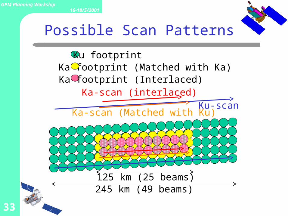
Ku-scanKa-scan (Matched with Ku)
Ka-scan (interlaced)
Ku footprintKa footprint (Matched with Ka)Ka footprint (Interlaced)
245 km (49 beams)125 km (25 beams)
Possible Scan Patterns