Embed Size (px)
Citation preview

METU BS536 Official Name : John Hancock Center 1
Other Names : Big John 1
Construction Period : 1965 – 1969 1
Location : Chicago, IL, USA 1
Architect : Bruce Graham (Skidmore, Owings & Merrill LLP) 1
Structural Engineering : Fazlur Rahman Khan (SOM) 1
Developer : Jerry Wolman Associates 1
Owner : Hearn Company 1
Building Function: Residential Office Commercial Parking 2
Architectural Height : 343.7 m / 1,128 ft 1
Height to Tip : 456.9 m / 1,499 ft 1
Floors Above Ground : 100 2
Number of Elevators : 50 2
Total Gross Floor Area : 260,126 m² / 2,799,973 ft² 1
Construction Cost : $95,000,000 2
Architectural Style : Structural Expressionism 2
Regional / National / City Ranking (by year 2015) : 8 / 8 / 4 1
1: John Hancock Center Project Facts, retrieved from http://skyscrapercenter.com/building/john hancock center/3452: John Hancock Center Project Facts, retrieved from http://www.emporis.com/buildings/116876/john hancock center chicago il usaFigure 3: Retrieved from http://legacy.skyscrapercenter.com/classimage.php/userpics/10004/?width=1000&height=800&image=/images/albums/userpics/10004/Hancock_ViewUp_AW.jpg
John Hancock Center PROJECT FACTS
Figure 1. John Hancock Building facadeMETU BArcheigh
Floo
ohn Hhn
Figur John
BS5369 1
USA 1
aham (Skidmore, Owings &Engineering : Fazlur Rahman Khan
oper y Wolman AssociateHearn Compan 1
nction: ResidHeigh
3636ECT A
Construction Material : Steel 2
Structural System :
According to Günel & Ay : Trussed – Tube System3,
According to Taranath: Trussed Tube System4,
According to Smith & Coull: Braced Tube Structure5
2: John Hancock Center Project Facts, retrieved from http://www.emporis.com/buildings/116876/john hancock center chicago il usa3: Gunel, H. & Ilg n, E. (2014). Tall Buildings: Structural Systems and Aerodynamic Form. Routledge–Taylor and Francis Book Company4: Taranath, B. (1998). Steel, Concrete & Composite Design of Tall Buildings, New York: McGraw–Hill Book Company5: Smith, B.S. & Coull, A. (1991). Tall Building Structures: Analysis and Design. New York: WileyFigure 2: Retrieved from http://www.greatbuildings.com/cgi bin/gbi.cgi/John_Hancock_Center.html/cid_1112340959_DSCN0708.html
John Hancock Center PROJECT FACTS
Figure 2. John Hancock Building exteriorMETU Tub
h & Coull: Tube
2: Jo HancockGun & IlTaran
i
Bystem3
4
e5
36666FAC
The five X bracings on each side go from floors 2 20,21 37, 38 55, 56 74, and 75 91. A half X brace extendsfrom 92 to 97. 2
The top roof is almost even with the 86th floor of theWillis (Sears) Tower. 2
The John Hancock Center was only the third building inthe world to be taller than 1,000 feet tall and the firstoutside of New York. The first two were the ChryslerBuilding in 1930 and the Empire State Building in 1931. 2
2: John Hancock Center Project Facts, retrieved from http://www.emporis.com/buildings/116876/john hancock center chicago il usaFigure 3: Retrieved from http://www.metalocus.es/content/en/system/files/file images/metalocus_john hancock center_09_1180.jpgFigure 4: Retrieved from http://www.greatbuildings.com/cgi bin/gbi.cgi/John_Hancock_Center.html/cid_1112341063_DSCN0711.html
John Hancock Center PROJECT FACTS
Figure 4. John Hancock Building exterior
Figure 3. John Hancock Building exteriorMEhn H
igure 3. J Ha
BS536irst
Chrysle931.
66FAC
The 344 m tall mixed use building is located at 875 North Michigan Avenue, Chicago, Illinois, United States. 7
7: John Hancock Center Location, retrieved from http://www.johnhancockcenterchicago.com/location.htmlFigure 5: Retrieved from http://www.metalocus.es/content/en/system/files/file images/metalocus_john hancock center_01_1180.jpg
John Hancock Center NEIGHBORHOOD
Figure 5. Aerial view of John Hancock CenterMEThe 34
Figure 5.
36666RHOO
Figure 6. View from Michigan Lake
John Hancock Center NEIGHBORHOOD
Figure 7. Exterior view,
Figure 6: Retrieved from http://www.metalocus.es/content/system/files/imagecache/blog_content_images/images lead/metalocus_john hancock center_40_0.jpgFigure 7: Retrieved from http://www.metalocus.es/content/en/system/files/file images/metalocus_john hancock center_02_1024.jpgMEFigure 6. View from Michigan La
U BS536666RHOO John Hancock Center ARCHITECTURAL DESIGN
Initially, there were two different potential design ideas:Two separate towers for offices and residential unitsSingle tower with mixed use option 8
8: John Hancock Center Case Study, retrieved from http://www.ctbuh.org/TallBuildings/FeaturedTallBuildings/JohnHancockCenterChicago/tabid/1959/language/enUS/Default.aspxFigure 8: Retrieved from http://retro.seals.ch/digbib/view?pid=bse pe 003:1982:6::63
Figure 8. Initial idea drawings
METInitially, there were t
Two sep
ohn H
3666DESI
Single tower scheme was chosen as it was beneficial forits occupancy on site. (60% of the block left open) 8
The mixed use program includes commercial spaces ona sub level and first five levels. It is followed by parking,32 stories of office and 50 stories of residential units. Atthe top, dining, observation and broadcasting facilitieswere placed. 9
The structure of the John Hancock Center measuresapproximately 80x50 m at the base and tapers to a topdimension of approximately 50x30 m. 9
The tapered shape allows larger office floors withlonger lease spans which are at the bottom; and smallerresidential floor areas which are located at the upperpart of the building. 9
Because of space constraints caused by the tower'stapering walls, common hallways and elevator lobbiesare narrower on higher floors.
John Hancock Center ARCHITECTURAL DESIGN
8: John Hancock Center Case Study, retrieved from http://www.ctbuh.org/TallBuildings/FeaturedTallBuildings/JohnHancockCenterChicago/tabid/1959/language/enUS/Default.aspx9: Iyengar, H. (2000) Reflections on the Hancock Concept, CTBUH Journal, Spring 2000Figure 9: Retrieved from http://www.metalocus.es/content/system/files/imagecache/blog_content_images/file images/metalocus_john hancock center_05_1180.jpg
Figure 9. Exterior view,METU ce fre at the bottom; and
as which are located at thg. 9
of space constraints caused by tng walls, common hallway
re narrower on hig
JohnDefau
Basuresa to
h
36666DESI
Construction started at 1965. 10
At the peak of construction, more than 2,000 peopleworked on the project; some five million man hourswere required to complete the development. 10
Prefabrication of the immense corner joints meantconstruction proceeded at a rapid pace up to threefloors a week. 10
John Hancock Center CONSTRUCTION
10: John Hancock Center, Design & Construction Highlights, retrieved from, http://www.360chicago.com/building history/Figure 10: Retrieved from http://www.metalocus.es/content/system/files/imagecache/blog_content_images/file images/metalocus_john hancock center_19_1024.jpgFigure 11: Retrieved from http://www.metalocus.es/content/system/files/imagecache/blog_content_images/file images/metalocus_john hancock center_18_800.jpg
Figure 10. Construction of the building Figure 11. Construction of the buildingMETU John
ure 1
BS53666UCTIO
The columns, diagonals and ties were fabricated to anI section composed of three independent plateswelded together. This shape was used as it greatlysimplified the Joint details. The maximum overalldimension of a column 91.5 cm x 91.5 cm. 11
John Hancock Center CONSTRUCTION
Figure 12. X brace at 12th floor, under construction,2
Figure 13. Construction of the building
11: John Hancock Center Steel fabrication details, retrieved from, http://retro.seals.ch/digbib/view?pid=bse pe 002:1982:6::160Figure 13: Retrieved from http://www.metalocus.es/content/en/blog/john hancock center skidmore owings merrill somFigure 14: Retrieved from http://www.metalocus.es/content/system/files/imagecache/blog_content_images/file images/metalocus_john hancock center_12_750.jpg
METUhe columns, diagonals and ties wsection composed ofelded together. This
simplified the Jodimension o
12th flo nstru
John
BS536666UCTIO
The structural engineer Fazlur R. Khan introduced a newstructural system, ‘Braced Tube Structure’, by combiningdiagonal bracing and exterior column system. The systemprovides significant steel usage and floor plan efficiency. 8
The diagonal trusses are clearly expressed in the facade. 8
The tapered form of the building significantly reduces thewind loads and need for more structural members.8
John Hancock Center BRACED TUBE STRUCTURE
8: John Hancock Center Case Study, retrieved from http://www.ctbuh.org/TallBuildings/FeaturedTallBuildings/JohnHancockCenterChicago/tabid/1959/language/enUS/Default.aspxFigure 15: Retrieved from http://legacy.skyscrapercenter.com/classimage.php/userpics/10002/?width=1000&height=800&image=/images/albums/userpics/10002/Ch0069.jpgFigure 16: Retrieved from http://legacy.skyscrapercenter.com/classimage.php/userpics/10002/?width=1000&height=800&image=/images/albums/userpics/10002/Ch035.jpg
Figure 14. John Hancock Center facade Figure 15. John Hancock Center corner detailMETU 8: John Hancock terUS/Default.aspxgure 1 tge.ph
e 1 John ancock C
BS53666CTU
To develop such a structural system, a historiccollaboration between architects and structuralengineers was implied. 12
Evolution of the system allows wider column spacing andlarger windows. 12
The exterior frames act as bearing walls, with gravityloads distributed uniformly among columns. 12
The bracings are generally 20 stories high and asecondary spandrel beam system infills the bracingpanels. 12
John Hancock Center BRACED TUBE STRUCTURE
Figures 17 18. Structural model axonometric andperspective views, Drawn by Olkan Naml
Figure 16. Structural modelaxonometric plan view,Drawn by Olkan Naml
12: John Hancock Center Structural engineering, retrieved from http://www.som.com/projects/john_hancock_center__structural_engineeringFigure 17 18 19: The structural model created based on the dimension data given in Iyengar, H. (2000) Reflections on the Hancock Concept, CTBUH Journal,Spring 2000 and http://skyscraper.org/EXHIBITIONS/TEN_TOPS/jhc.php. Dimensions are approximated.
METU uctural
etric plan view,by Olkan Naml
ohn
BS536andbracing
66CTU
John Hancock Center BRACED TUBE STRUCTURE
Figures 20 21 . Elevations of the structure, Drawn by Olkan NamlFigure 19. Top view of the structure, Drawn by Olkan Naml
At initial design stages, the architectural team did notwant the bracings to move higher than 90th floorbecause of architectural causes, such as preventing theview. 13
Fazlur Khan argued about that since terminatingdiagonals abruptly at 90th level would increase the needof steel and therefore, the cost significantly. 13
Finally, teams were agreed and the bracings were placedto the top 10 floors. 13
13: Kahn, F. (1982) 100 story John Hancock Center in Chicago: a case study of the design process, retrieved from http://dx.doi.org/10.5169/seals 26292Figure 20 21 21: The structural model created based on the dimension data given in Iyengar, H. (2000) Reflections on the Hancock Concept, CTBUH Journal,Spring 2000 and http://skyscraper.org/EXHIBITIONS/TEN_TOPS/jhc.php. Dimensions are approximated.
METU Figure 19. To
Kahn
BS53666CTU
e placed
John Hancock Center BRACED TUBE STRUCTURE
Figure 22. Ground level floor plan,
Drawn by Olkan Naml
Figure 23: John Hancock Center floor plan generated from structural model based on the dimension data given in Iyengar, H. (2000) Reflections on the HancockConcept, CTBUH Journal, Spring 2000 and http://skyscraper.org/EXHIBITIONS/TEN_TOPS/jhc.php Dimensions are approximated.
Distances between cornercolumns and first columnsdecrease as the building rises.
Lease span of the buildingdecreases from ~17 meters to~8 meters as the building rises.METase span of these span of the bse span of thecreases from ~1
~8 meters as
3666CTU John Hancock Center BRACED TUBE STRUCTURE
Figure 23. 48th level floor plan,
Drawn by Olkan Naml
Figure 24: John Hancock Center floor plan generated from structural model based on the dimension data given in Iyengar, H. (2000) Reflections on the HancockConcept, CTBUH Journal, Spring 2000 and http://skyscraper.org/EXHIBITIONS/TEN_TOPS/jhc.php Dimensions are approximated.MET
36666CTU John Hancock Center BRACED TUBE STRUCTURE
Figure 24. Top level floor plan,
Drawn by Olkan Naml
Figure 25: John Hancock Center floor plan generated from structural model based on the dimension data given in Iyengar, H. (2000) Reflections on the HancockConcept, CTBUH Journal, Spring 2000 and http://skyscraper.org/EXHIBITIONS/TEN_TOPS/jhc.php Dimensions are approximated.
The first columns after thecorner columns rise until 92ndfloor. Corner columns keeprising until the top level.METU BS536666
CTU
John Hancock Center BRACED TUBE STRUCTURE
Figure 25 26. Structural Perspectives,
Drawn by Olkan Naml
Figure 26 27 28: John Hancock Center floor plan generated from structural model based on the dimension data given in Iyengar, H. (2000) Reflections on theHancock Concept, CTBUH Journal, Spring 2000 and http://skyscraper.org/EXHIBITIONS/TEN_TOPS/jhc.php. Dimensions are approximated.METU BS53666
CTU John Hancock Center INTERIOR & DIAGONALS
The expressed diagonals of the facade have notadversely affected the quality of interior spaces. Onthe contrary, they are often coveted and decorated ina variety of ways, thus adding individual character toapartments. 9
Figures 27 28. Diagonals from interior
9: Iyengar, H. (2000) Reflections on the Hancock Concept, CTBUH Journal, Spring 2000Figure 29 30: Retrieved from http://faculty.arch.tamu.edu/media/cms_page_media/4433/JohnHancockCenter.pdf
MEFigures 27 28. gona
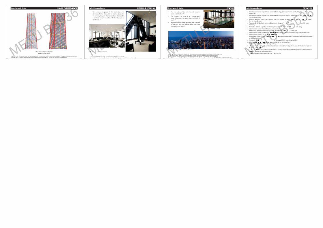
BS53666ONA John Hancock Center INTERIOR
The observatory of the John Hancock Center islocated at 94th floor. 10
The elevators that move up to the observatorytravel 96 floors at a top speed of approximately 35km/h. 10
America's highest indoor swimming pool is locatedon the 44th floor. The pool is carved out of themechanical floor below. 2
2: John Hancock Center Project Facts, retrieved from http://www.emporis.com/buildings/116876/john hancock center chicago il usa10: John Hancock Center, Design & Construction Highlights, retrieved from, http://www.360chicago.com/building history/Figure 31: Retrieved from http://www.som.com/FILE/14693/johnhancock_1264x722_ezra_stolleresto_04.jpg?h=800&s=17Figure 32: Retrieved from http://www.360chicago.com/assets/components/phpthumbof/cache/south view night 01.17fd681d5b38d5b001523965379cdc20.jpg
Figure 30. View from John Hancock Center Observatory
Figure 29. Swimming pool at floor 44
METUJohnJohn
Figure Vie from hn Ha
BS53666TERI
Figure 29. Swimming pool
John Hancock Center REFERENCES
1. John Hancock Center Project Facts, retrieved from http://skyscrapercenter.com/building/john hancockcenter/345
2. John Hancock Center Project Facts, retrieved from http://www.emporis.com/buildings/116876/john hancockcenter chicago il usa
3. Gunel, H. & Ilg n, E. (2014). Tall Buildings: Structural Systems and Aerodynamic Form. Routledge–Taylor andFrancis Book Company
4. Taranath, B. (1998). Steel, Concrete & Composite Design of Tall Buildings, New York: McGraw–Hill BookCompany
5. Smith, B.S. & Coull, A. (1991). Tall Building Structures: Analysis and Design. New York: Wiley6. John Hancock Center Project Timeline, retrieved from
http://www.chicagoarchitecture.info/Building/1006/The John Hancock Center.php7. John Hancock Center Location, retrieved from http://www.johnhancockcenterchicago.com/location.html8. John Hancock Center Case Study, retrieved from
http://www.ctbuh.org/TallBuildings/FeaturedTallBuildings/JohnHancockCenterChicago/tabid/1959/language/en US/Default.aspx
9. Iyengar, H. (2000) Reflections on the Hancock Concept, CTBUH Journal, Spring 200010. John Hancock Center, Design & Construction Highlights, retrieved from,
http://www.360chicago.com/building history/11. 11: John Hancock Center Steel fabrication details, retrieved from, http://retro.seals.ch/digbib/view?pid=bse
pe 002:1982:6::16012. Kahn, F. (1982) 100 story John Hancock Center in Chicago: a case study of the design process, retrieved from
http://dx.doi.org/10.5169/seals 2629213. http://skyscraper.org/EXHIBITIONS/TEN_TOPS/jhc.phpMETU uildi
fromStudy, re from
g/TallBuildings/FeaturedTalx
(2000) ons Hancockancoc te n & C
ttp://www.360chicago.com/buil1: Joh Hanco ter002:1982:6::160
12. Kahn, (1982) 100http://dx.doi
13. http://s
BS53666RENC
ohn cock
ldings/116876/john hancock
rodynamic Form. Routledge–Tay
Buildings, New rk: cGra
res: Analysis e NewomThe J ancww.johnha


![Consider... [[Tall(John) Tall(John)]] [[Tall(John)]] = undecided, therefore [[Tall(John) Tall(John)]] = undecided](https://img.pdfslide.net/doc/110x75/5515d816550346cf6f8b4964/consider-talljohn-talljohn-talljohn-undecided-therefore-talljohn-talljohn-undecided.jpg)
![ONE WORLD TRADE CENTER BS5 36 U BSB TUU BS Busers.metu.edu.tr/archstr/BS536/documents/Projects/One World Trade... · t nter/98 2] e Tr ectory.: ... Second design modified to 70th](https://img.pdfslide.net/doc/110x75/5aabeb8b7f8b9aa06a8c7ec2/one-world-trade-center-bs5-36-u-bsb-tuu-bs-world-tradet-nter98-2-e-tr-ectory.jpg)