Embed Size (px)
Citation preview

IM76330 rev 06.28.16www.amp-research.com 1/13
I N S T A L L A T I O N G U I D E
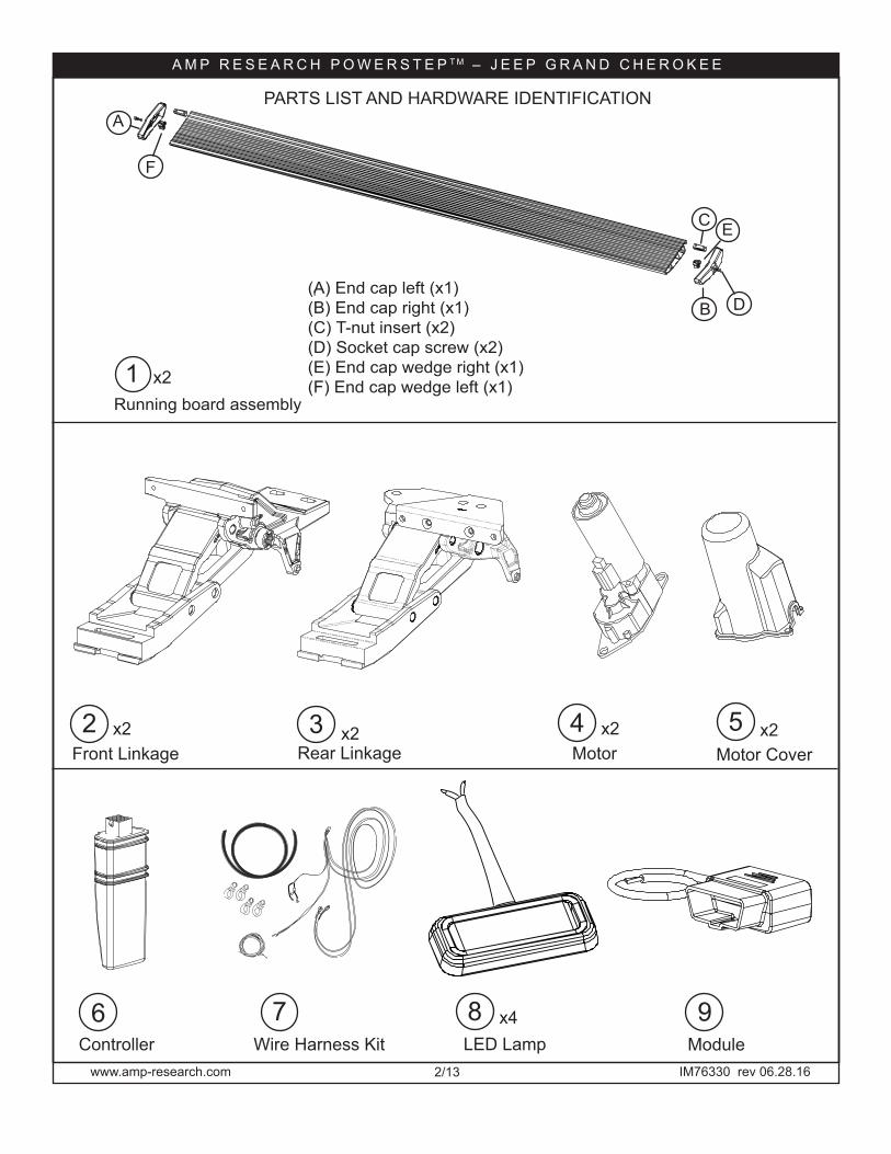
APPLICATION YEAR AMP PART#
Jeep Grand Cherokee 2014–2016 76330-01A
Invented, engineered and manufactured exclusively by AMP Research in the USA. May be covered by one of the following patents: 6,641,158; 6,830,257; 6,834,875; 6,938,909; 7,055,839; 7,380,807; 7,398,985; 7,584,975 ©2012 AMP Research. All rights reserved. Printed in USA.
5-Year Limited WarrantyWARRANTY
3-5 HoursProfessional installation recommended
Fits these trim models:
75th AnniversaryLaredoLaredo EAltitudeLimitedOverland
Does not fit these models:
High altitudeSRTSRT Red VaporSummitSummit CA Ed.
Fits 4 x 2 and 4 x 4Does not fit vehicles with gas tank skid plates, but does fit with front skid plates.
INSTALLATION TIME
1 2 3 4SKILL LEVEL
4= Experienced
AMP RESEARCH TECH SUPPORT 1-888-983-2204 (Press 2) Monday - Friday, 6:00 AM - 5:00 PM PST
TOOLS REQUIREDq Safety Gogglesq Measuring Tapeq 9/16" Wrench q 7/16” Wrenchq 10mm Wrenchq 13mm Wrenchq 13mm Socketq 10mm Socketq Ratchet Wrench and Extensionq Wire Stripper / Cutterq 3/16” Hex Key (allen wrench)q 1/8” and 17/32” Drill Bitq Center Punch q Anti Corrosion Paint q Electrical Tape q Utility Knife q Small flat blade screwdriver q Heat gun q Silicon Spray or equivalent q Drill
www.amp-research.com 2/13
A M P R E S E A R C H P O W E R S T E P T M – J E E P G R A N D C H E R O K E E
IM76330 rev 06.28.16
3Rear Linkage
4
7Controller
PARTS LIST AND HARDWARE IDENTIFICATION
2 x2Front Linkage
6
Motor Cover
5Motor
x2
8Wire Harness Kit
9
x2x2
x4LED Lamp
1Running board assembly
DB(A) End cap left (x1)(B) End cap right (x1)(C) T-nut insert (x2)(D) Socket cap screw (x2)(E) End cap wedge right (x1) (F) End cap wedge left (x1)
A
C E
F
x2
Module

www.amp-research.com 3/13
A M P R E S E A R C H P O W E R S T E P T M – J E E P G R A N D C H E R O K E E
IM76330 rev 06.28.16
10 x8Socket Cap Screw
11 12Hex Flange Bolt
x4 13Black washer
17x20Cable Tie 6”
18x2Cable Tie 11”
x4Posi-Lock Connector
x8
15 x6Cinch Fastener
16
2120
x8Butt Connector
19
24
x2Shim
22 23
Hex bolt
26
x8 14
Rivet Nutx2
Spacerx2
Conical Washer Bolt
Rivet Nut Tool Kit (Installation Tool)
Serrated Nut
25
x2 x2Hex Flange Bolt
Tubing (Installation Tool)
27Grommet
www.amp-research.com 4/13
A M P R E S E A R C H P O W E R S T E P T M – J E E P G R A N D C H E R O K E E
IM76330 rev 06.28.16
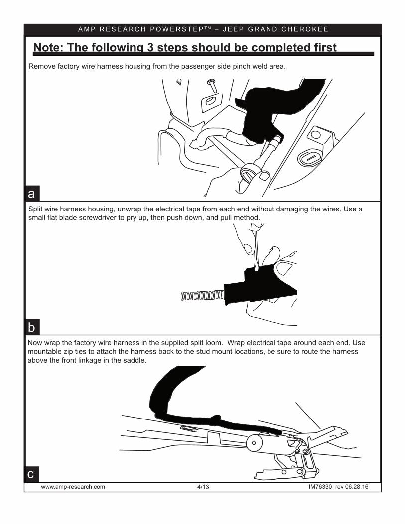
Remove factory wire harness housing from the passenger side pinch weld area.
Split wire harness housing, unwrap the electrical tape from each end without damaging the wires. Use a small flat blade screwdriver to pry up, then push down, and pull method.
Note: The following 3 steps should be completed first
15
c
13
b
a
Now wrap the factory wire harness in the supplied split loom. Wrap electrical tape around each end. Use mountable zip ties to attach the harness back to the stud mount locations, be sure to route the harness above the front linkage in the saddle.
www.amp-research.com 5/13
A M P R E S E A R C H P O W E R S T E P T M – J E E P G R A N D C H E R O K E E
IM76330 rev 06.28.16www.amp-research.com2
1
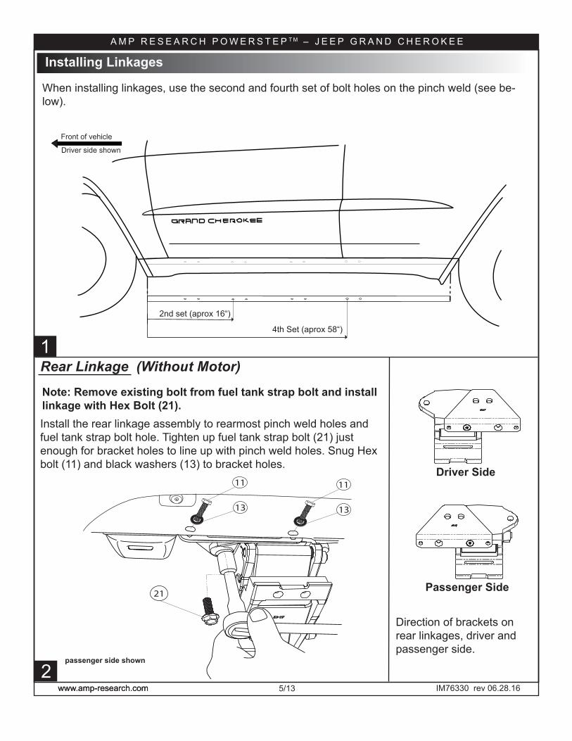
Install the rear linkage assembly to rearmost pinch weld holes and fuel tank strap bolt hole. Tighten up fuel tank strap bolt (21) just enough for bracket holes to line up with pinch weld holes. Snug Hex bolt (11) and black washers (13) to bracket holes.
11
13
21
11
13
Installing Linkages
Note: Remove existing bolt from fuel tank strap bolt and install linkage with Hex Bolt (21).
Rear Linkage (Without Motor)
Driver Side
Passenger Side
passenger side shown
Driver side shown
Front of vehicle
4th Set (aprox 58“)
2nd set (aprox 16“)
When installing linkages, use the second and fourth set of bolt holes on the pinch weld (see be-low).
Direction of brackets on rear linkages, driver and passenger side.
www.amp-research.com 6/13
A M P R E S E A R C H P O W E R S T E P T M – J E E P G R A N D C H E R O K E E
IM76330 rev 06.28.16www.amp-research.com
5
7
4 4
6
8
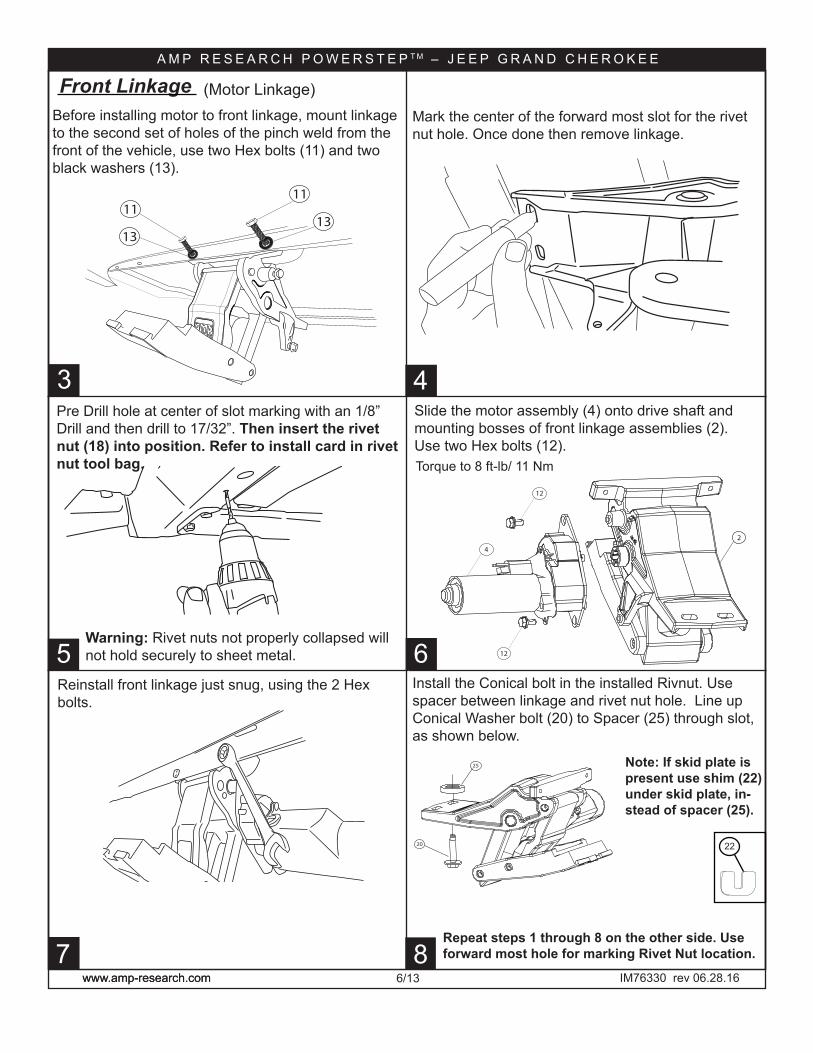
Pre Drill hole at center of slot marking with an 1/8” Drill and then drill to 17/32”. Then insert the rivet nut (18) into position. Refer to install card in rivet nut tool bag.
Warning: Rivet nuts not properly collapsed will not hold securely to sheet metal.
Repeat steps 1 through 8 on the other side. Use forward most hole for marking Rivet Nut location.
Reinstall front linkage just snug, using the 2 Hex bolts.
Note: If skid plate is present use shim (22) under skid plate, in-stead of spacer (25).
Slide the motor assembly (4) onto drive shaft and mounting bosses of front linkage assemblies (2). Use two Hex bolts (12).
Mark the center of the forward most slot for the rivet nut hole. Once done then remove linkage.
3
12
12
4
2
Front Linkage
25
20
Install the Conical bolt in the installed Rivnut. Use spacer between linkage and rivet nut hole. Line up Conical Washer bolt (20) to Spacer (25) through slot, as shown below.
(Motor Linkage)
11
1311
13
Before installing motor to front linkage, mount linkage to the second set of holes of the pinch weld from the front of the vehicle, use two Hex bolts (11) and two black washers (13).
Torque to 8 ft-lb/ 11 Nm
22

www.amp-research.com 7/13
A M P R E S E A R C H P O W E R S T E P T M – J E E P G R A N D C H E R O K E E
IM76330 rev 06.28.16
15
13
11 1512
14
Route driver side leg down thru engine bay as seen here.
Open the Fuse box, (see step 10 for location of fuse box in engine compartment) connect the Red wire to positive power post located on top left corner of the fuse box.
Install controller on passenger side wire harness bundle next to the ECU. Secure with 11” cable ties. Connect the Black wire to bolt on ECU.
9
Installing Electrical ComponentsRoute the long wire harness leg along the top of the firewall and then down away from the steering shaft and exhaust to sub frame then back to pinch weld area. The other leg shall go along the Fuse box, then down away from the exhaust and to the pinch weld area. Zip tie as needed.
Remove the fuse from the Powerstep wire harness.
+7
Fuse Box
10
ECU
ECU
The two purple wires left from the harness will con-nect with wires that will be fed through from under the passenger side. See next steps.
www.amp-research.com 8/13
A M P R E S E A R C H P O W E R S T E P T M – J E E P G R A N D C H E R O K E E
IM76330 rev 06.28.16
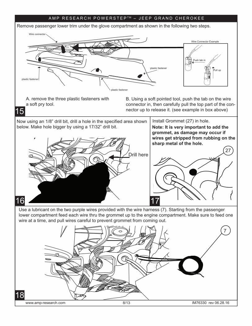
15B. Using a soft pointed tool, push the tab on the wire connector in, then carefully pull the top part of the con-nector up to release it. (see example in box above)
16
18
Push tab in
Pull up
plastic fastener
Wire Connector Example
Remove passenger lower trim under the glove compartment as shown in the following two steps.
A. remove the three plastic fasteners with a soft pry tool.
plastic fastener
plastic fastener
Wire connector
Drill here
Install Grommet (27) in hole.
27
Use a lubricant on the two purple wires provided with the wire harness (7). Starting from the passenger lower compartment feed each wire thru the grommet up to the engine compartment. Make sure to feed one wire at a time, and pull wires careful to prevent grommet from coming out.
7
Now using an 1/8” drill bit, drill a hole in the specified area shown below. Make hole bigger by using a 17/32” drill bit.
17
Note: It is very important to add the grommet, as damage may occur if wires get stripped from rubbing on the sharp metal of the hole.
www.amp-research.com 9/13
A M P R E S E A R C H P O W E R S T E P T M – J E E P G R A N D C H E R O K E E
IM76330 rev 06.28.16
21
22
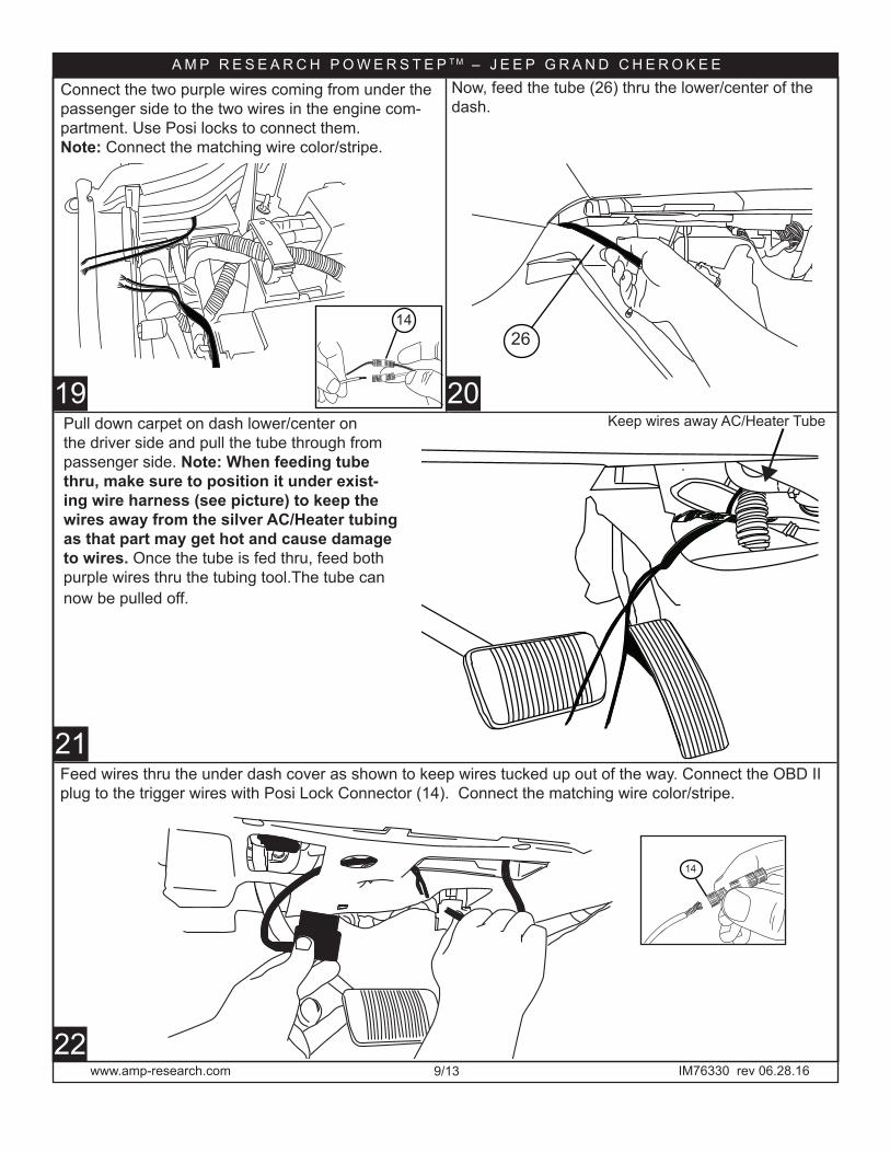
Now, feed the tube (26) thru the lower/center of the dash.
Pull down carpet on dash lower/center on the driver side and pull the tube through from passenger side. Note: When feeding tube thru, make sure to position it under exist-ing wire harness (see picture) to keep the wires away from the silver AC/Heater tubing as that part may get hot and cause damage to wires. Once the tube is fed thru, feed both purple wires thru the tubing tool.The tube can now be pulled off.
Feed wires thru the under dash cover as shown to keep wires tucked up out of the way. Connect the OBD II plug to the trigger wires with Posi Lock Connector (14). Connect the matching wire color/stripe.
14
26
Connect the two purple wires coming from under the passenger side to the two wires in the engine com-partment. Use Posi locks to connect them.Note: Connect the matching wire color/stripe.
14
19 20Keep wires away AC/Heater Tube
www.amp-research.com 10/13
A M P R E S E A R C H P O W E R S T E P T M – J E E P G R A N D C H E R O K E E
IM76330 rev 06.28.16
15
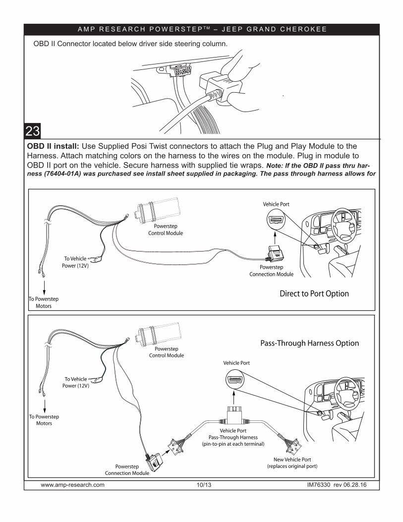
OBD II install: Use Supplied Posi Twist connectors to attach the Plug and Play Module to the Harness. Attach matching colors on the harness to the wires on the module. Plug in module to OBD II port on the vehicle. Secure harness with supplied tie wraps. Note: If the OBD II pass thru har-ness (76404-01A) was purchased see install sheet supplied in packaging. The pass through harness allows for
Vehicle Port
Vehicle Port
Powerstep
Connection Module
Powerstep
Connection Module
Vehicle Port
Pass-Through Harness
(pin-to-pin at each terminal)
New Vehicle Port
(replaces original port)
To Powerstep
Motors
To Vehicle
Power (12V)
Powerstep
Control Module
To Powerstep
Motors
To Vehicle
Power (12V)
Powerstep
Control Module
Direct to Port Option
Pass-Through Harness Option
13 23
Vehicle Port
Vehicle Port
Powerstep
Connection Module
Powerstep
Connection Module
Vehicle Port
Pass-Through Harness
(pin-to-pin at each terminal)
New Vehicle Port
(replaces original port)
To Powerstep
Motors
To Vehicle
Power (12V)
Powerstep
Control Module
To Powerstep
Motors
To Vehicle
Power (12V)
Powerstep
Control Module
Direct to Port Option
Pass-Through Harness Option
OBD II Connector located below driver side steering column.
www.amp-research.com 11/13
A M P R E S E A R C H P O W E R S T E P T M – J E E P G R A N D C H E R O K E E
IM76330 rev 06.28.16www.amp-research.com
4 2524
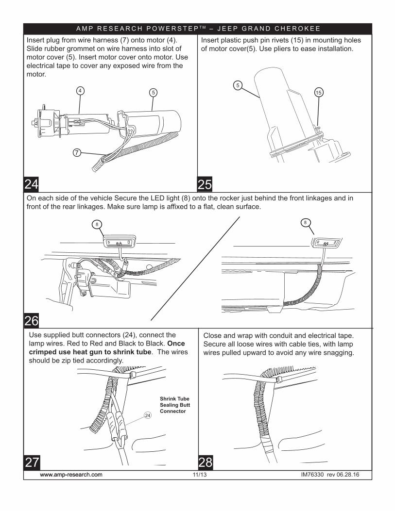
Insert plug from wire harness (7) onto motor (4). Slide rubber grommet on wire harness into slot of motor cover (5). Insert motor cover onto motor. Use electrical tape to cover any exposed wire from the motor.
4 5
7
Insert plastic push pin rivets (15) in mounting holes of motor cover(5). Use pliers to ease installation.
515
26
27 28
Use supplied butt connectors (24), connect the lamp wires. Red to Red and Black to Black. Once crimped use heat gun to shrink tube. The wires should be zip tied accordingly.
On each side of the vehicle Secure the LED light (8) onto the rocker just behind the front linkages and in front of the rear linkages. Make sure lamp is affixed to a flat, clean surface.
24
Close and wrap with conduit and electrical tape. Secure all loose wires with cable ties, with lamp wires pulled upward to avoid any wire snagging.
8 8
Shrink Tube Sealing Butt Connector
www.amp-research.com 12/13
A M P R E S E A R C H P O W E R S T E P T M – J E E P G R A N D C H E R O K E E
IM76330 rev 06.28.16
30
1029
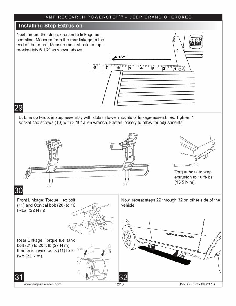
Torque bolts to step extrusion to 10 ft-lbs (13.5 N m).
Now, repeat steps 29 through 32 on other side of the vehicle.
31
Next, mount the step extrusion to linkage as-semblies. Measure from the rear linkage to the end of the board. Measurement should be ap-proximately 6 1/2” as shown above.
10 10
10 10
Installing Step Extrusion
Rear Linkage: Torque fuel tank bolt (21) to 20 ft-lb (27 N m) then pinch weld bolts (11) to16 ft-lb (22 N m).
Front Linkage: Torque Hex bolt (11) and Conical bolt (20) to 16 ft-lbs. (22 N m).
11
13
21
11
13
32
123456
6 1/2”
78
B. Line up t-nuts in step assembly with slots in lower mounts of linkage assemblies. Tighten 4 socket cap screws (10) with 3/16” allen wrench. Fasten loosely to allow for adjustments.
www.amp-research.com 13/13
A M P R E S E A R C H P O W E R S T E P T M – J E E P G R A N D C H E R O K E E
IM76330 rev 06.28.1634
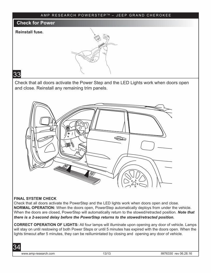
33Check that all doors activate the Power Step and the LED Lights work when doors open and close. Reinstall any remaining trim panels.
CORRECT OPERATION OF LIGHTS: All four lamps will illuminate upon opening any door of vehicle. Lamps will stay on until restowing of both Power Steps or until 5 minutes has expired with the doors open. When the lights timeout after 5 minutes, they can be reillumintated by closing and opening any door of vehicle.
FINAL SYSTEM CHECKCheck that all doors activate the PowerStep and the LED lights work when doors open and close.NORMAL OPERATION: When the doors open, PowerStep automatically deploys from under the vehicle. When the doors are closed, PowerStep will automatically return to the stowed/retracted position. Note that there is a 2-second delay before the PowerStep returns to the stowed/retracted position.
Reinstall fuse.
Reinstall fuse.
Check for Power


Automatic power deploy:The running boards will extend down and out when the doors are opened.
Automatic power stow:The running boards will return to the stowed position when the doors are closed. There will be a 2-seconddelay before the running boards move to the stowed position.
Automatic stop:If an object is in the way of the moving running board, the running board will automatically stop.To reset, clear any obstruction, then simply open and close the door to resume normal operation.
Manually set in the deployed (OUT) position for access to the roof:
your foot while at the same time closing the door. To resume normal operation, open and close the door.
Maintenance: In adverse conditions, debris such as mud, dirt, and salt may become trapped in the runningboard mechanism, possibly leading to unwanted noise. If this occurs, manually set the running boards to
Avoid spraying the motors directly. After washing, apply silicone spray lubricant to the hinge pivot pins.Do not apply silicone, wax or protectants like Armor All® to the running board stepping surface.
Caution! Keep hands away when the running board is in motion.
™ Congratulations on your purchase of thegenuine AMP Research PowerStep!Here’s what you should know...
AMP RESEARCH warrants this product to be free from defects in material and workmanship for FIVE (5) YEARS FROMDATE OF PURCHASE, provided there has been normal use and proper maintenance. This warranty applies to the originalpurchaser only. All remedies under this warranty are limited to the repair replacement of the product itself, or the repairor replacement of any component part thereof, found by the factory to be defective within the time period speci�ed. Thedecision to repair or replace is wholly within the discretion of the manufacturer.
for instructions. You must retain proof of purchase and submit a copy with any items returned for warranty work. Uponcompletion of warranty work, if any, we will return the repaired or replaced item or items to you freight prepaid. Damageto our products caused by accidents, �re, vandalism, negligence, misinstallation, misuse, Acts of God, or by defective partsnot manufactured by us, is not covered under this warranty.
ANY IMPLIED WARRANTIES OF MERCHANTABILITY AND/OR FITNESS FOR A PARTICULAR PURPOSE CREATED HEREBY ARELIMITED IN DURATION TO THE SAME DURATION AND SCOPE AS THE EXPRESS WRITTEN WARRANTY. OUR COMPANY SHALLNOT BE LIABLE FOR ANY INCIDENTAL OR CONSEQUENTIAL DAMAGE.
Some states do not allow limitations on how long an implied warranty lasts, or the exclusion or limitation of incidentalor consequential damages, so the above limitations or exclusions may not apply to you. This warranty gives you speci�clegal rights, and you may also have other rights that vary from state to state.
FOR WARRANTY ISSUES WITH THIS PRODUCT PLEASE CALL AMP RESEARCH CUSTOMER SERVICE 1-888-983-2204
5-YEAR LIMITED WARRANTY
WARNING
Be sure to read and precisely follow the provided instructions when installing this product. Failure to do so could place the vehicleoccupants in a potentially dangerous situation. After installing or reinstalling, re-check to insure that the product is properly installed.
AMP Research PowerStep running boards automatically movewhen the doors are opened to assist entering and exiting the vehicle.