Embed Size (px)
Citation preview
11
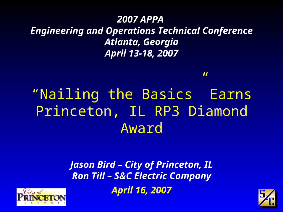
2007 APPA Engineering and Operations Technical Conference
Atlanta, GeorgiaApril 13-18, 2007
“Nailing the Basics” Earns Princeton, IL RP3 Diamond Award
Jason Bird – City of Princeton, ILRon Till – S&C Electric Company
April 16, 2007
22
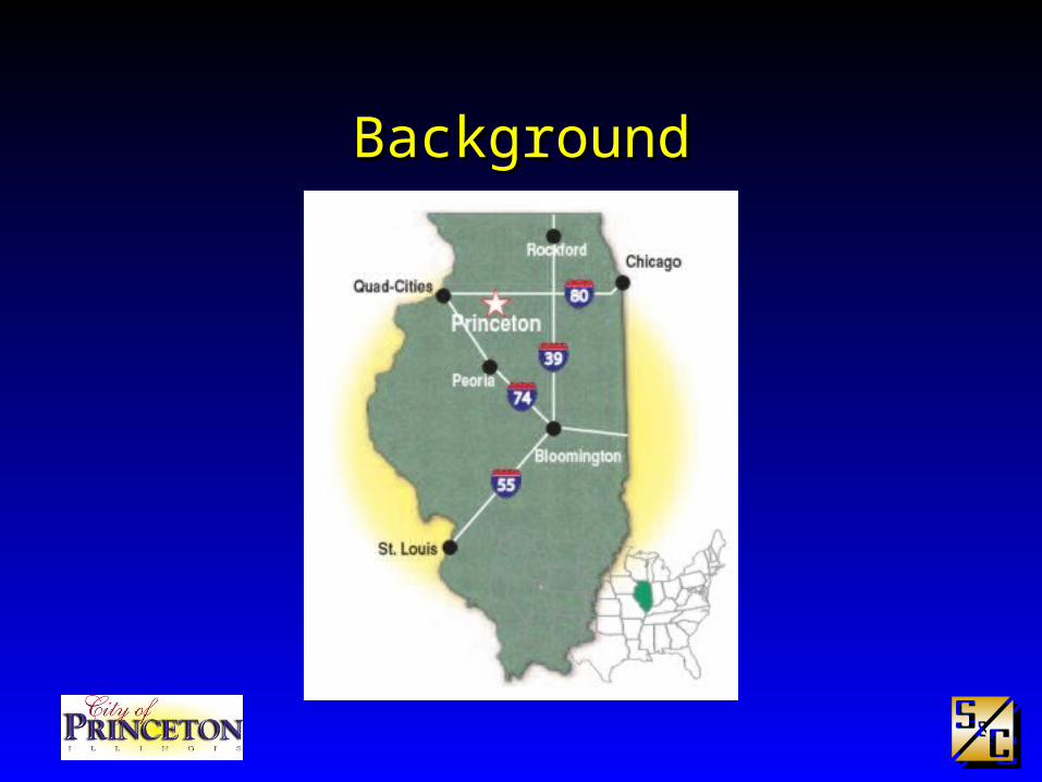
BackgroundBackground
33
BackgroundBackground
County Seat of Bureau County Illinois
Area about 7.0 mi2
Population about 7,500 (2000)
City Owned Electric and Telecom Utilities
19 Electrical and Power Plant Employees
44
BackgroundBackground
Approximately 4,300 Customers
12 distribution circuits
70% overhead line
30% underground
55
BackgroundBackground
Receives bulk power at 138 kV
2 major substations:
138 kV => 34.5 kV and 12.47 kV
34.5 kV => 12.47 kV and 2.4 kV
Eight (8) multi-fuel engine-generators sets
• Used for summer peak shaving or export
66

77
The ChallengeThe Challenge
Major substation upgrade planned, but City didn’t have proper information to specify equipment or implement protection settings Short-circuit study required
Coordination study required
88
The ChallengeThe Challenge
Nearly 80% of the time transformer primary fuse, line fuse, and feeder breaker would operate
No reclosing relay on feeder breakers meant extended outages to Customers for transient faults
Need to improve reliability to Customers

99
The Solution The Solution
S&C engineers spent 2 days in the field collecting data for the studies.
• Nameplate information
• Line conductor sizes, configurations and lengths
• Verified existing system maps
• Review existing transformer and line fusing practices
1010
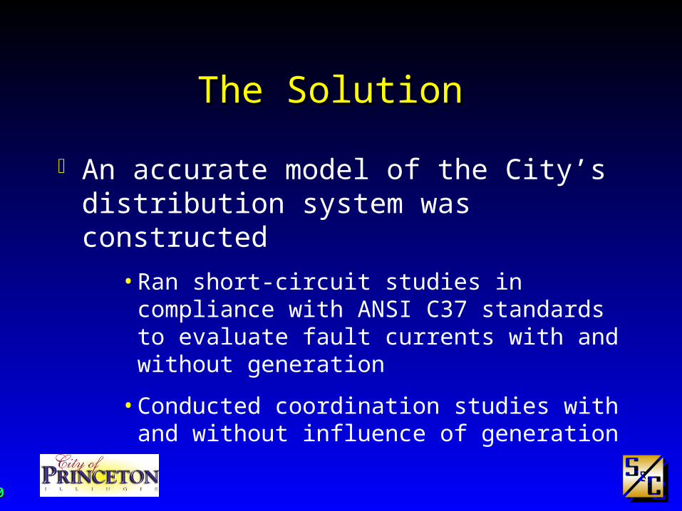
The Solution The Solution
An accurate model of the City’s distribution system was constructed
• Ran short-circuit studies in compliance with ANSI C37 standards to evaluate fault currents with and without generation
• Conducted coordination studies with and without influence of generation
1111
Study ResultsStudy Results
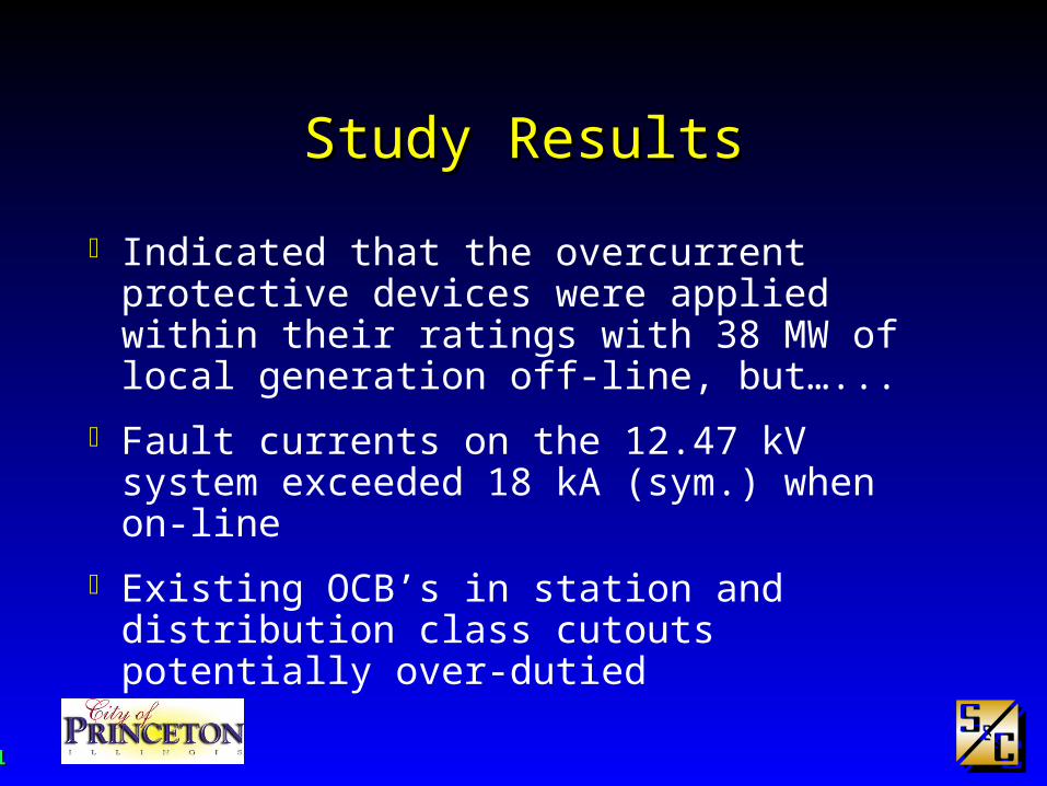
Indicated that the overcurrent protective devices were applied within their ratings with 38 MW of local generation off-line, but…...
Fault currents on the 12.47 kV system exceeded 18 kA (sym.) when on-line
Existing OCB’s in station and distribution class cutouts potentially over-dutied
1212
Study ResultsStudy Results
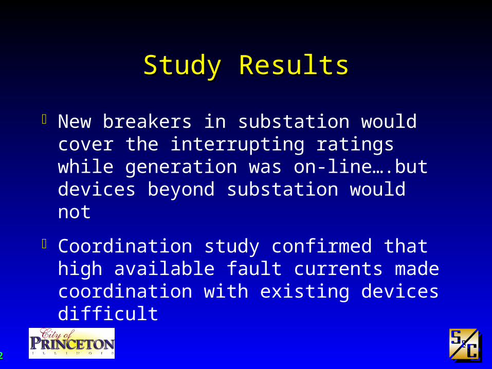
New breakers in substation would cover the interrupting ratings while generation was on-line….but devices beyond substation would not
Coordination study confirmed that high available fault currents made coordination with existing devices difficult

1313
Proposed ChangesProposed Changes
Evaluate ratings of distribution class cutouts City was already using Positrol® Fuse Links, so for
purposes of establishing interrupting ratings, assumed Type XS Open Cutouts had been applied universally on system
Largest fuse link in inventory was 100 Amperes, so two styles of cutouts to choose from:
1414
Proposed ChangesProposed Changes
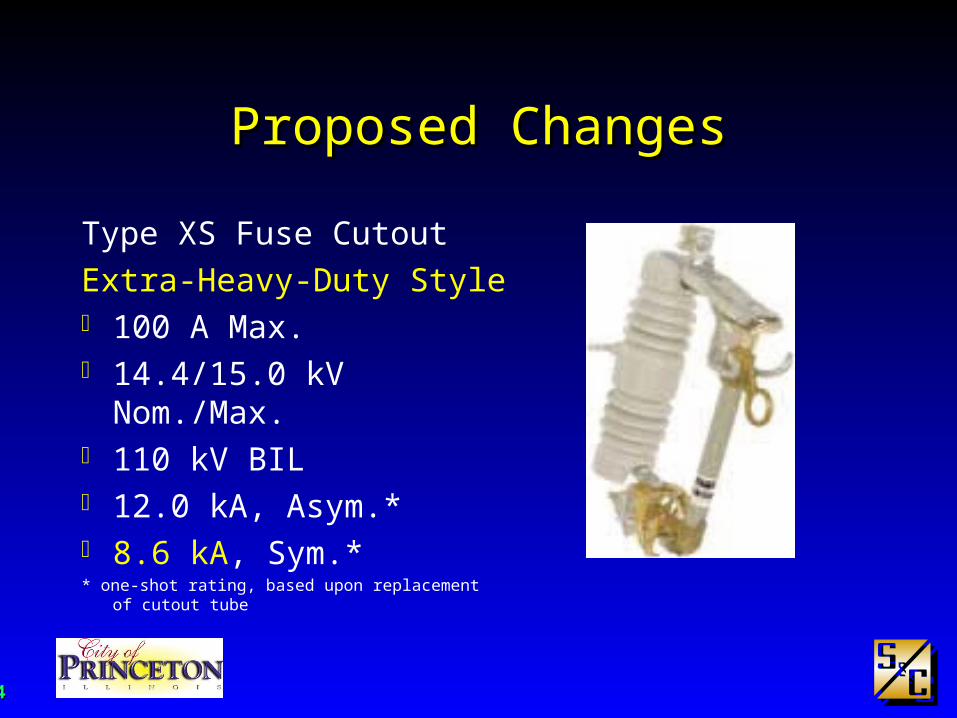
Type XS Fuse Cutout
Extra-Heavy-Duty Style 100 A Max. 14.4/15.0 kV Nom./Max. 110 kV BIL 12.0 kA, Asym.* 8.6 kA, Sym.** one-shot rating, based upon replacement of cutout tube

1515
Proposed ChangesProposed Changes
Type XS Fuse Cutout
Ultra-Heavy-Duty Style 100 A Max. 14.4/15.0 kV Nom./Max. 110 kV BIL 16.0 kA, Asym. 10.6 kA, Sym.

1616
Proposed ChangesProposed Changes
With generators off-line, Extra-Heavy-Duty Style cutouts were capable of interrupting fault currents on any feeder when they were placed a minimum of 1,000 circuit-feet away from the substation
Considered fault duty and X/R ratio
• ANSI C37.42-1996
– EHD tested at X/R = 8
– UHD tested at X/R = 12

1717
Proposed ChangesProposed Changes
However, when the generators are on-line, the available fault currents are too high….need to go with Ultra-Heavy-Duty Style cutouts or even Power Fuses close to or in the substation
1818
Proposed ChangesProposed Changes
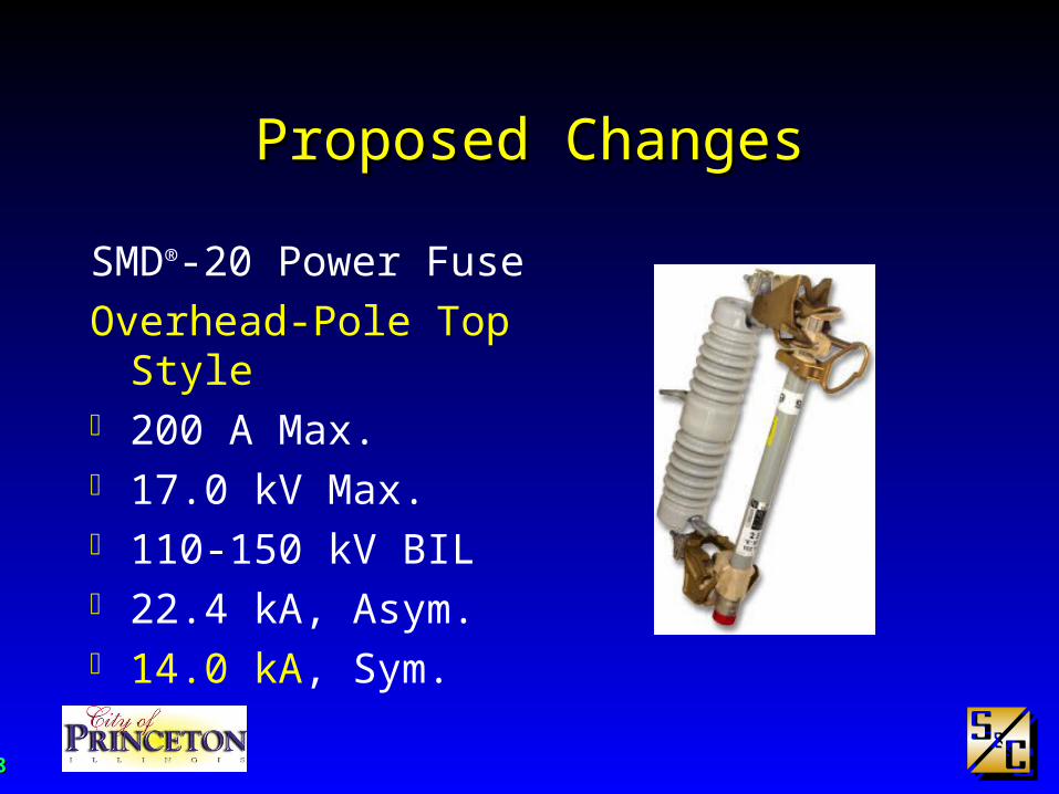
SMD®-20 Power Fuse
Overhead-Pole Top Style 200 A Max. 17.0 kV Max. 110-150 kV BIL 22.4 kA, Asym. 14.0 kA, Sym.
1919
Proposed ChangesProposed Changes
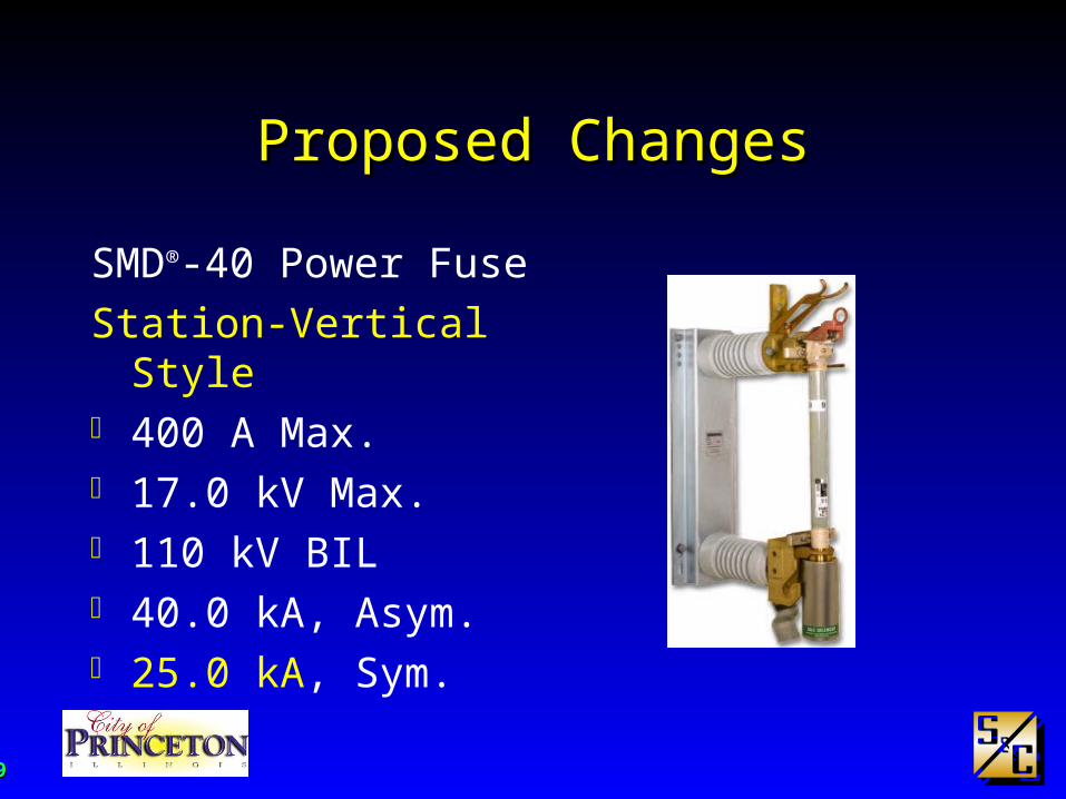
SMD®-40 Power Fuse
Station-Vertical Style 400 A Max. 17.0 kV Max. 110 kV BIL 40.0 kA, Asym. 25.0 kA, Sym.

2020
Proposed ChangesProposed Changes
Fault Tamer® Fuse Limiter 20 A Max. 15.0 kV Max. 110-125 kV BIL 12.0 kA, Sym. 15,700 Max. I2t

2121
Proposed ChangesProposed Changes
Listed the minimum number of circuit-feet and geographic locations for the application of each type of device with the generators on-line
2222
BenefitsBenefits
Protective devices applied within ratings
Standardization of protective devices / switches
Reliability has gone up
Customer satisfaction has increased
More time to perform maintenance / inspections
2323
Study ResultsStudy Results
Start by standardizing transformer fusing One simple chart for line crews
Minimize stock on trucks
Then select line fusing criteria

2424
kVA Ratings
S&C StandardSpeed
(TCC No. 123-6)
S&C "K“Speed
(TCC No.165-6)
S&C "FaultTamer”
(TCC No.450-8)
Single-Phase Three-Phase FLAFuse Link(Amperes)
Fuse Link (Amperes)
Fuse Cartridge(Amperes)
3 9 0.42 1 6K 10
5 15 0.69 2 6K 10
10 30 1.39 3 6K 10
15 45 2.08 5 6K 10
25 75 3.47 7 8K 10
37.5 112.5 5.21 10 10K 10
50 150 6.94 15 12K 10
75 225 10.4 20 20K 20
100 300 13.9 25 25K 20
167 500 23.1 40 40K -
250 750 34.7 65 65K -
333 1000 46.3 80 80K -
* conn. Δ-Δ, Δ-Y, and Y-Y
2525
PLOTTING VOLTAGE:
BY:
DATE:
NO:
EXISTING SETTINGS
S&C Electric Company
Chicago, Illinois 60626
Power Systems Services
12.47 kV
0.01
0.1
1
10
100
1000
0.5 1 10 100 1000 10000
Current in Amperes: x 10 at 12.47 kV and x 3.625 at 34.4 kV.
Tim
e in
Se
con
ds
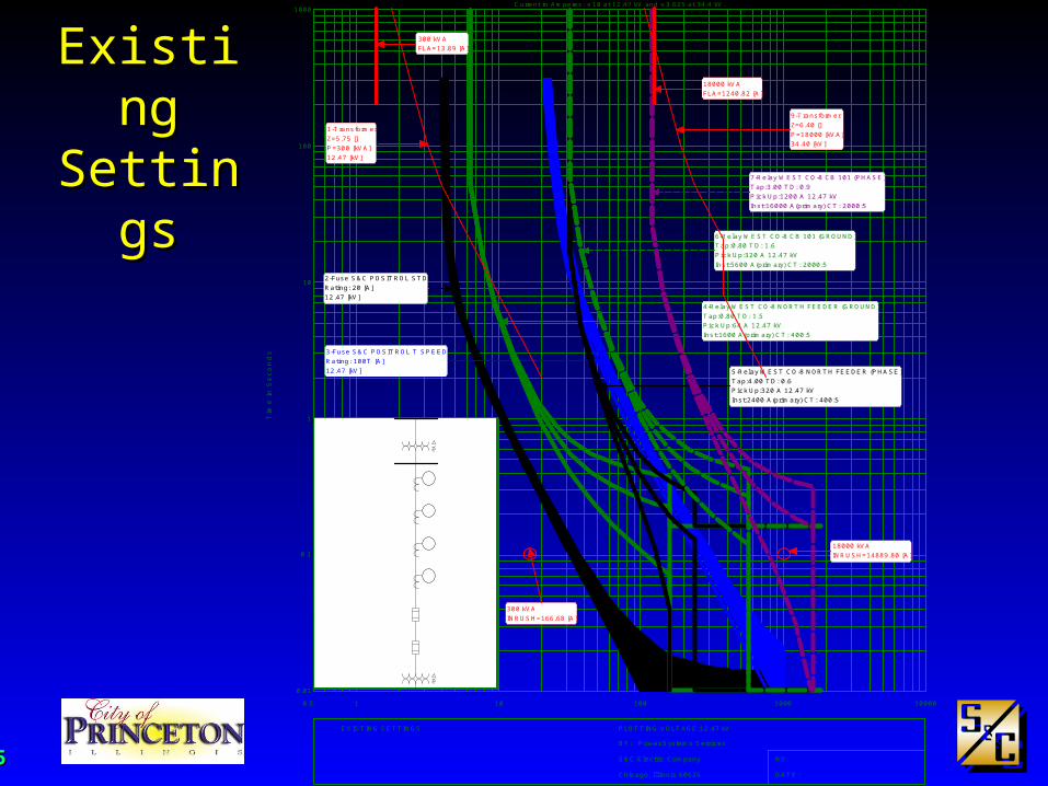
2-Fuse S&C POSITROL STDRating: 20 [A]12.47 [kV]
3-Fuse S&C POSITROL T SPEEDRating: 100T [A]12.47 [kV]
4-Relay WEST CO-8 NORTH FEEDER (GROUND)Tap:0.80 TD: 1.5Pick Up:64 A 12.47 kVInst:1600 A(primary) CT: 400:5
5-Relay WEST CO-8 NORTH FEEDER (PHASE)Tap:4.00 TD: 0.6Pick Up:320 A 12.47 kVInst:2400 A(primary) CT: 400:5
6-Relay WEST CO-8 CB 101 (GROUND)Tap:0.80 TD: 1.6Pick Up:320 A 12.47 kVInst:5600 A(primary) CT: 2000:5
7-Relay WEST CO-8 CB 101 (PHASE)Tap:3.00 TD: 0.9Pick Up:1200 A 12.47 kVInst:16000 A(primary) CT: 2000:5
300 kVAFLA=13.89 [A]
300 kVAINRUSH=166.68 [A]
1-TransformerZ=5.75 []P=300 [kVA]12.47 [kV]
18000 kVAFLA=1240.82 [A]
18000 kVAINRUSH=14889.80 [A]
9-TransformerZ=6.40 []P=18000 [kVA]34.40 [kV]
12.47 kV
34.5 kV
300kVA
18MVA
12.47 kV
34.5 kV
300kVA
18MVA
Existing Existing SettingsSettings

2626
Alternate Alternate SettingsSettings
PLOTTING VOLTAGE:
BY:
DATE:
NO:
ALTERNATE SETTINGS
S&C Electric Company
Chicago, Illinois 60626
Power Systems Services
12.47 kV
0.01
0.1
1
10
100
1000
0.5 1 10 100 1000 10000
Current in Amperes: x 10 at 12.47 kV and x 3.625 at 34.4 kV.
Tim
e in
Se
con
ds
2-Fuse S&C POSITROL STDRating: 20 [A]12.47 [kV]
3-Fuse S&C POSITROL T SPEEDRating: 100T [A]12.47 [kV]
4-Relay WEST CO-8 NORTH FEEDER (GROUND)Tap:0.80 TD: 1.5Pick Up:64 A 12.47 kVInst:1600 A(primary) CT: 400:5
5-Relay WEST CO-8 NORTH FEEDER (PHASE)Tap:4.00 TD: 0.6Pick Up:320 A 12.47 kVInst:2400 A(primary) CT: 400:5
6-Relay WEST CO-8 CB 101 (GROUND)Tap:0.80 TD: 1.6Pick Up:320 A 12.47 kVInst:5600 A(primary) CT: 2000:5
7-Relay WEST CO-8 CB 101 (PHASE)Tap:3.00 TD: 0.9Pick Up:1200 A 12.47 kVInst:16000 A(primary) CT: 2000:5
18000 kVAFLA=1240.82 [A]
18000 kVAINRUSH=14889.80 [A]
9-TransformerZ=6.40 []P=18000 [kVA]34.40 [kV]
300 kVAFLA=13.89 [A]
300 kVAINRUSH=166.68 [A]
1-TransformerZ=5.75 []P=300 [kVA]12.47 [kV]
2727
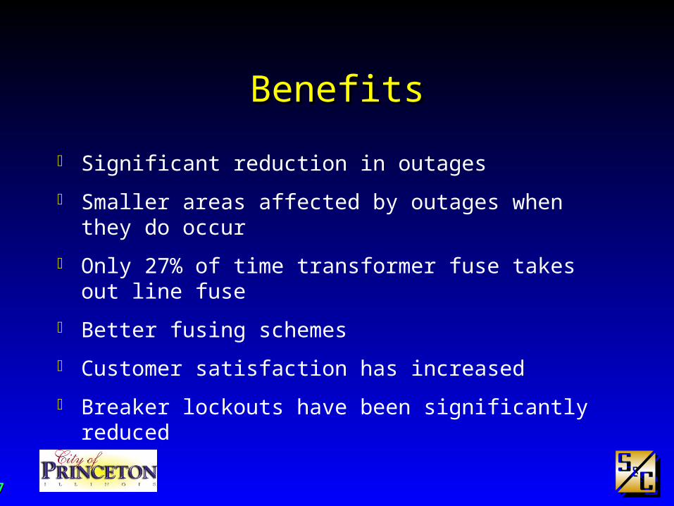
BenefitsBenefits
Significant reduction in outages
Smaller areas affected by outages when they do occur
Only 27% of time transformer fuse takes out line fuse
Better fusing schemes
Customer satisfaction has increased
Breaker lockouts have been significantly reduced