Embed Size (px)
Citation preview
© F
erro
met
al 0
8/20
15
7.65Kysy saatavuus / Ask for availability
Suomi +358- 10 308 11 Latvia & Lithuania +371- 672 80 581
Eesti +372- 6990 470 www.ferrometal.fi
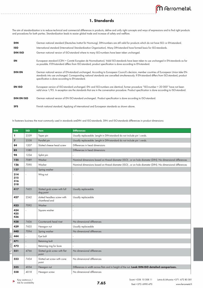
1. Standards
DIN German national standard (Deutsches Institut für Normung). DIN-numbers are still valid for products which do not have ISO- or EN-standard.
ISO International standard (International Standardization Organisation). Many DIN-standard have formed basis for ISO-standards.
DIN ISO German national version of ISO-standard where to many ISO-numbers have been taken unchanged.
EN Euroapean standard (CEN = Comité Européen de Normalisation). Valid ISO-standards have been taken to use unchanged in EN-standards as far as possible. If EN-standard differs from ISO-standard, product specification is done according to EN-standard.
DIN EN German national version of EN-standard unchanged. According to Euroapean Council’s decision, member countries of Euroapean Union take EN- standards into use unchanged. Corresponding national standards are cancelled simultaneously. If EN-standard differs from ISO-standard, product specification is done according to EN-standard.
EN ISO Euroapean version of ISO-standard unchanged. EN- and ISO-numbers are identical, former procedure “ISO-number + 20 000” have not been valid since 1/95. In exception are the standards that are in the conversation procedure. Product specification is done according to ISO-standard.
DIN EN ISO German national version of EN ISO-standard unchanged.. Product specification is done according to ISO-standard.
SFS Finnish national standard. Applying of International and Euroapean standards as shown above.
The aim of standardization is to reduce technical and commercial differences in products, define and unify right concepts and ways of expressions and to find right products and procedures for both parties. Standardization leads to easier global trade and increase of safety and wellfare.
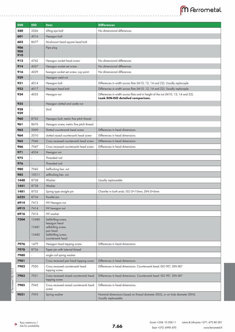
In fasteners business the most commonly used in standards areDIN- and ISO-standards. DIN- and ISO-standards differences in product dimensions:
DIN ISO Item Differences
1 2339 Taper pin Usually replaceable. Lenght in DIN-standard do not include pin´s ends.
7 2338 Parallel pin Usually replaceable. Lenght in DIN-standard do not include pin´s ends.
84 1207 Slotted cheese head screw Differences in head dimensions
85 1580 Differences in head dimensions
94 1234 Splint pin -
125 7089 Washer Nominal dimensions based on thread diameter (ISO) , or on hole diameter (DIN). No dimensional differences
126 7090 Washer Nominal dimensions based on thread diameter (ISO) , or on hole diameter (DIN). No dimensional differences
127 - Spring washer -
314315316318
- Wing nut -
417 7435 Slotted grub screw with full dog point
Usually replaceable
427 2342 slotted headless screw with chamfered end
Usually replaceable
433 7092 Washer -
434 435 436
- Square washer -
438 7436 Countersank head rivet No dimensional differences
439 7435 Hexagon nut Usually replaceable
440 7094 Spring washer No dimensional differences
444 - Eye bolt -
471 - Retaining bolt -
472 - Retaining ring for bore -
551 4766 Slotted grub screw with flat point
No dimensional differences
553 7434 Slotted set screw with cone point
No dimensional differences
555 4034 Hexagon nut Differences in width across flats and in height of the nut. Look DIN-ISO detailed comparison.
558 4018 Hexagon screw No dimensional differences
© F
erro
met
al 0
8/20
15
7.66Kysy saatavuus / Ask for availability
Suomi +358- 10 308 11 Latvia & Lithuania +371- 672 80 581
Eesti +372- 6990 470 www.ferrometal.fi
DIN ISO Item Differences
580 3266 Lifting eye bolt No dimensional differences.
601 4016 Hexagon bolt
603 8677 Mushroom head square head bolt -
906908910
- Pipe plug -
912 4762 Hexagon socket head screw No dimensional differences
914 4027 Hexagon socket set screw No dimensional differences
916 4029 hexagon socket set screw, cup point No dimensional differences
929 - Hexagon weld nut -
931 4014 Hexagon bolt Differences in width across flats (M10, 12, 14 and 22). Usually replacaple
933 4017 Hexagon head bolt Differences in width across flats (M10, 12, 14 and 22). Usually replacaple
934 4032 Hexagon nut Differences in width across flats and in height of the nut (M10, 12, 14 and 22). Look DIN-ISO detailed comparison.
935 - Hexagon slotted and castle nut -
938939
- Stud -
960 8765 Hexagon bolt, metric fine pitch thread -
961 8676 Hexagon screw, metric fine pitch thread -
963 2009 Slotted countersank head screw Differences in head dimensions
964 2010 slotted raised countersank head screw Differences in head dimensions
965 7046 Cross recessed countersank head screw Differences in head dimensions
966 7047 Cross recessed countersank head screw Differences in head dimensions
971 4034 Hexagon nut -
975 - Threaded rod -
976 - Threaded rod -
980 7042 Selflocking hex. nut -
985 10511 selflocking hex. nut
1440 8738 Washer Usually replaceable
1441 8738 Washer -
1481 8752 Spring type straight pin Chamfer in both ends: ISO D<10mm, DIN D<6mm
6325 8734 Parallel pin -
6914 7412 HV Hexagon nut -
6915 7414 HV hexagon nut -
6916 7416 HV washer -
7504 15480
15481
15482
Selfdrilling screw,hexagon headselfdrilling screw,pan headSelfdrilling screw,countersank head
-
7976 1479 Hexagon head tapping screw Differences in head dimensions
7978 8736 Taper pin with internal thread -
7980 - single coil spring washer -
7981 Cross recessed pan head tapping screw Differences in head dimensions
7982 7050 Cross recessed countersank head tapping screw
Differences in head dimensions. Countersank head: ISO 90º, DIN 80º
7983 7051 Cross recessed raised countersank head tapping screw
Differences in head dimensions. Countersank head: ISO 90º, DIN 80º
7985 7045 Cross recessed raised countersank head screw
Differences in head dimensions.
9021 7093 Spring washer Nominal dimensions based on thread diameter (ISO), or on hole diameter (DIN). Usually replaceable.
© F
erro
met
al 0
8/20
15
7.67Kysy saatavuus / Ask for availability
Suomi +358- 10 308 11 Latvia & Lithuania +371- 672 80 581
Eesti +372- 6990 470 www.ferrometal.fi
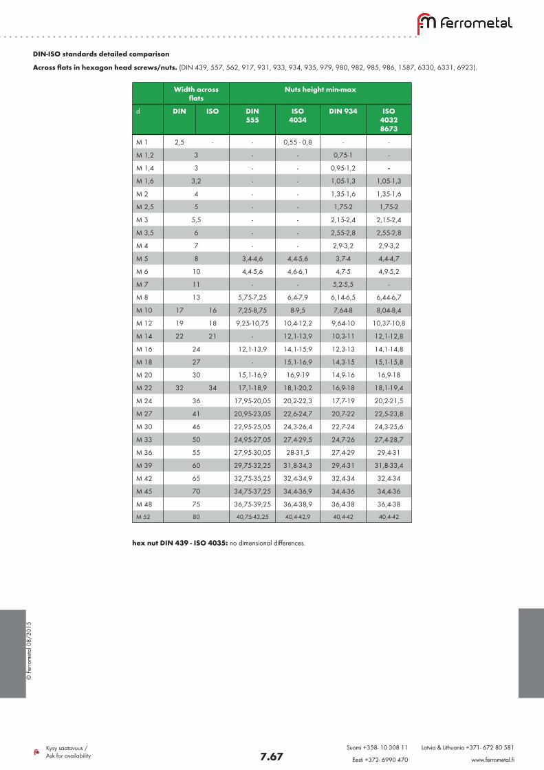
Across flats in hexagon head screws/nuts. (DIN 439, 557, 562, 917, 931, 933, 934, 935, 979, 980, 982, 985, 986, 1587, 6330, 6331, 6923).
Width across flats
Nuts height min-max
d DIN ISO DIN 555
ISO 4034
DIN 934 ISO40328673
M 1 2,5 - - 0,55 - 0,8 - -
M 1,2 3 - - 0,75-1 -
M 1,4 3 - - 0,95-1,2 -
M 1,6 3,2 - - 1,05-1,3 1,05-1,3
M 2 4 - - 1,35-1,6 1,35-1,6
M 2,5 5 - - 1,75-2 1,75-2
M 3 5,5 - - 2,15-2,4 2,15-2,4
M 3,5 6 - - 2,55-2,8 2,55-2,8
M 4 7 - - 2,9-3,2 2,9-3,2
M 5 8 3,4-4,6 4,4-5,6 3,7-4 4,4-4,7
M 6 10 4,4-5,6 4,6-6,1 4,7-5 4,9-5,2
M 7 11 - - 5,2-5,5 -
M 8 13 5,75-7,25 6,4-7,9 6,14-6,5 6,44-6,7
M 10 17 16 7,25-8,75 8-9,5 7,64-8 8,04-8,4
M 12 19 18 9,25-10,75 10,4-12,2 9,64-10 10,37-10,8
M 14 22 21 - 12,1-13,9 10,3-11 12,1-12,8
M 16 24 12,1-13,9 14,1-15,9 12,3-13 14,1-14,8
M 18 27 - 15,1-16,9 14,3-15 15,1-15,8
M 20 30 15,1-16,9 16,9-19 14,9-16 16,9-18
M 22 32 34 17,1-18,9 18,1-20,2 16,9-18 18,1-19,4
M 24 36 17,95-20,05 20,2-22,3 17,7-19 20,2-21,5
M 27 41 20,95-23,05 22,6-24,7 20,7-22 22,5-23,8
M 30 46 22,95-25,05 24,3-26,4 22,7-24 24,3-25,6
M 33 50 24,95-27,05 27,4-29,5 24,7-26 27,4-28,7
M 36 55 27,95-30,05 28-31,5 27,4-29 29,4-31
M 39 60 29,75-32,25 31,8-34,3 29,4-31 31,8-33,4
M 42 65 32,75-35,25 32,4-34,9 32,4-34 32,4-34
M 45 70 34,75-37,25 34,4-36,9 34,4-36 34,4-36
M 48 75 36,75-39,25 36,4-38,9 36,4-38 36,4-38
M 52 80 40,75-43,25 40,4-42,9 40,4-42 40,4-42
hex nut DIN 439 - ISO 4035: no dimensional differences.
DIN-ISO standards detailed comparison
© F
erro
met
al 0
8/20
15
7.68Kysy saatavuus / Ask for availability
Suomi +358- 10 308 11 Latvia & Lithuania +371- 672 80 581
Eesti +372- 6990 470 www.ferrometal.fi
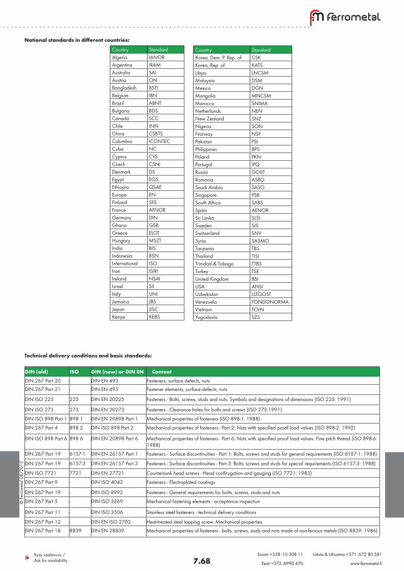
National standards in different countries:
Country StandardAlgeria IANORArgentina IRAMAustralia SAIAustria ONBangladesh BSTIBelgium IBNBrazil ABNTBulgaria BDSCanada SCCChile INNChina CSBTSColumbia ICONTECCuba NCCyprus CYSCzech CSNIDenmark DSEgypt EOSEthiopia QSAEEurope ENFinland SFSFrance AFNORGermany DINGhana GSBGreece ELOTHungary MSZTIndia BISIndonesia BSNInternational ISOIran ISIRIIreland NSAIIsrael SIIItaly UNIJamaica JBSJapan JISCKenya KEBS
Country StandardKorea, Dem. P. Rep. of CSKKorea, Rep. of KATSLibya LNCSMMalaysia DSMMexico DGNMongolia MNCSMMarocco SNIMANetherlands NENNew Zealand SNZNigeria SONNorway NSFPakistan PSIPhilippines BPSPoland PKNPortugal IPQRussia GOSTRomania ASROSaudi Arabia SASOSingapore PSBSouth Africa SABSSpain AENORSri Lanka SLSISweden SISSwitzerland SNVSyria SASMOTanzania TBSThailand TISITrinidad & Tobago TTBSTurkey TSEUnited Kingdom BSIUSA ANSIUzbekistan UZGOSTVenezuela FONDONORMAVietnam TCVNYugoslavia SZS
Technical delivery conditions and basic standards:
DIN (old) ISO DIN (new) or DIN EN ContentDIN 267 Part 20 - DIN EN 493 Fasteners, surface defects, nutsDIN 267 Part 21 - DIN EN 493 Fastener elements, surface defects, nuts
DIN ISO 225 225 DIN EN 20225 Fasteners - Bolts, screws, studs and nuts. Symbols and designations of dimensions (ISO 225: 1991)
DIN ISO 273 273 DIN EN 20273 Fasteners - Clearance holes for bolts and screws (ISO 273:1991)
DIN ISO 898 Part 1 898 1 DIN EN 20898 Part 1 Mechanical properties of fasteners (ISO 898-1: 1988)
DIN 267 Part 4 898 2 DIN ISO 898 Part 2 Mechanical properties of fasteners - Part 2: Nuts with specified proof load values (ISO 898-2: 1992)
DIN ISO 898 Part 6 898 6 DIN EN 20898 Part 6 Mechanical properties of fasteners - Part 6: Nuts with specified proof load values. Fine pitch thread (ISO 898-6: 1988)
DIN 267 Part 19 6157-1 DIN EN 26157 Part 1 Fasteners - Surface discontinuities - Part 1: Bolts, screws and studs for general requirements (ISO 6157-1: 1988)
DIN 267 Part 19 6157-3 DIN EN 26157 Part 3 Fasteners - Surface discontinuities - Part 3: Bolts, screws and studs for special requirements (ISO 6157-3: 1988)
DIN ISO 7721 7721 DIN EN 27721 Countersunk head screws - Head confirugation and gauging (ISO 7721: 1983)
DIN 267 Part 9 - DIN ISO 4042 Fasteners - Electroplated coatings
DIN 267 Part 19 - DIN ISO 8992 Fasteners - General requirements for bolts, screws, studs and nuts
DIN 267 Part 5 - DIN ISO 3269 Mechanical fastening elements - acceptance inspection
DIN 267 Part 11 - DIN ISO 3506 Stainless steel fasteners - technical delivery conditions
DIN 267 Part 12 - DIN EN ISO 2702 Heat-treated steel tapping screw. Mechanical properties.
DIN 267 Part 18 8839 DIN EN 28839 Mechanical properties of fasteners - bolts, screws, studs and nuts made of non-ferrous metals (ISO 8839: 1986)
© F
erro
met
al 0
8/20
15
7.69Kysy saatavuus / Ask for availability
Suomi +358- 10 308 11 Latvia & Lithuania +371- 672 80 581
Eesti +372- 6990 470 www.ferrometal.fi
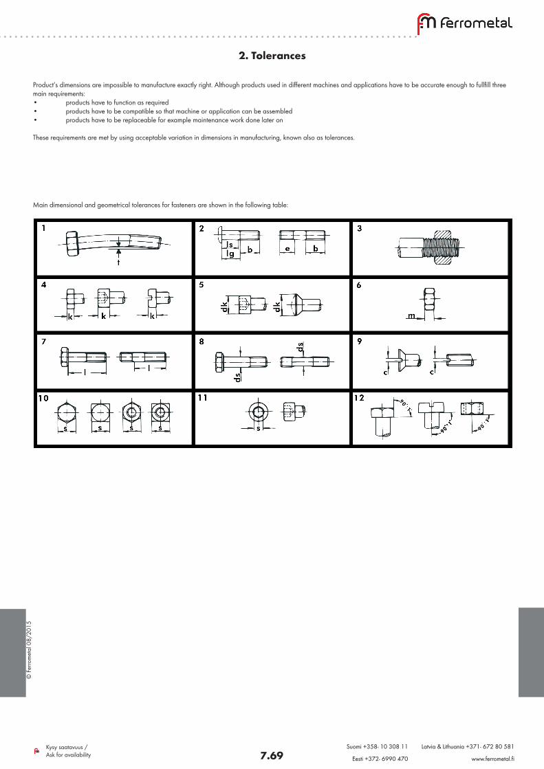
2. Tolerances
Product’s dimensions are impossible to manufacture exactly right. Although products used in different machines and applications have to be accurate enough to fullfill three main requirements:• products have to function as required• products have to be compatible so that machine or application can be assembled• products have to be replaceable for example maintenance work done later on
These requirements are met by using acceptable variation in dimensions in manufacturing, known also as tolerances.
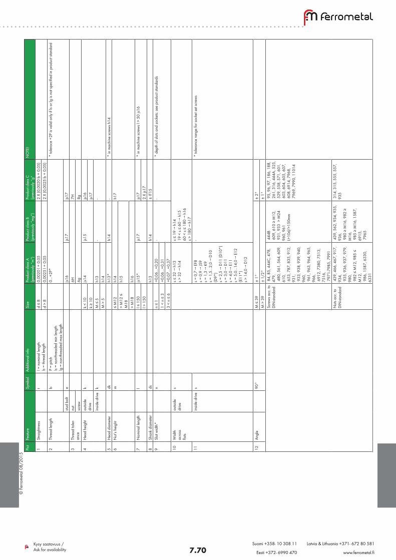
Main dimensional and geometrical tolerances for fasteners are shown in the following table:
© F
erro
met
al 0
8/20
15
7.70Kysy saatavuus / Ask for availability
Suomi +358- 10 308 11 Latvia & Lithuania +371- 672 80 581
Eesti +372- 6990 470 www.ferrometal.fi
Pict
Feat
ure
Sym
bol
Addi
tiona
l inf
oSi
zePr
oduc
t cla
ss A
(p
revio
usly
“m
”)Pr
oduc
t cla
ss B
(p
revio
usly
“m
g”)
Prod
uct c
lass
C
(pre
vious
ly “
g”N
OTE
!
1St
raig
htne
sst
l =
nom
inal
leng
th
b =
thre
ad le
ngth
d ≤
80,
0020
l +
0,05
2 X
(0,0
020
b +
0,05
)d
> 8
0,00
25 l
+ 0,
052
X (0
,002
5 b
+ 0,
05)
2Th
read
leng
thb
P =
pitc
h ls
= n
on-th
read
ed m
in le
ngth
lg
= n
on-th
read
ed m
ax le
ngth
0…+2
P* *
tole
race
+2P
is v
alid
onl
y if
ls or
lg is
not
spec
ified
in p
rodu
ct st
anda
rd
stud
bolt
ejs1
6js1
7js1
73
Thre
ad to
ler-
ance
nut
6H7H
scre
w6g
8g4
Hea
d he
ight
outsi
de
drive
kk
< 10
js14
js15
js16
k ≥
10js1
7in
side
drive
kM
≤ 5
h13
--
M >
5h1
45
Hea
d di
amet
erdk
h13*
h14
- *
in m
achi
ne sc
rew
s h14
6N
ut’s
heig
htm
≤ M
12h1
4h1
7>
M12
≤
M18
h15
> M
18h1
67
Nom
inal
leng
thl
l ≤ 1
50js1
5*js1
7js1
7 *
in m
achi
ne sc
rew
s l >
50
js16
l > 1
502
X js1
78
Shan
k di
amet
erds
h13
h14
± IT
159
Slot
wid
th*
nn
≤ 1
+0,0
6…+0
,20
--
* d
epth
of s
lots
and
sock
ets:
see
prod
uct s
tand
ards
1
< n
≤ 3
+0,0
6…+0
,31
3 <
n ≤
6+0
,07…
+0,3
710
Wid
th
acro
ss
flats
outsi
de
drive
ss ≤
32
→ h
13
s > 3
2 →
h14
s ≤ 1
9 →
h14
19
< s
≤ 60
→ h
15
60 <
s ≤
180
→ h
16
s > 1
80 →
h17
11in
side
drive
ss =
0,7
→ E
F8
s = 0
,9 →
JS9
s = 1
,3 →
K9
s = 1
,5…
2,0
→ D
10
(D9*
) s =
2,5
→ D
11 (D
10*)
s =
3,0
→ D
11
s = 4
,0 →
E11
s =
5,0
…14
,0 →
E12
(E
11*)
s >
14,
0 →
D12
- *
tole
ranc
e ra
nge
for s
ocke
t set
scre
ws
12An
gle
90°
M ≤
39
± 1°
± 2°
M >
39
± 1/
2°±
1°Sc
rew
s acc
. to
DIN
-stan
dard
84,
85,
444
C, 4
78,
479,
4
80, 5
61, 5
64, 6
09,
610,
6
53, 7
87, 8
35, 9
12,
931,
9
33, 9
38, 9
39, 9
40,
960,
9
61, 9
63, 9
64, 9
65,
966,
6
912,
738
0, 7
513,
75
16,
797
1-79
85, 7
991
444
B 6
09, 6
10 ≥
M12
, 9
31, 9
33 >
M24
96
0, 9
61
L>10
d/>1
50m
m
95,
96,
97,
186
, 188
, 2
61, 3
16, 4
44A,
525
, 5
29, 5
58, 5
71, 6
01,
603
, 604
, 605
, 607
, 6
08, 6
914,
796
8,
796
9, 7
990,
110
14
Nut
s acc
. to
DIN
-stan
dard
439
, 466
, 467
, 917
, 93
4,
935
, 936
, 937
, 979
, 98
0,
982
≤ M
12, 9
85 ≤
M
12,
986
, 158
7, 6
330,
63
31
439
, 562
, 934
, 935
, 93
6,
980
≥ M
16, 9
82 ≥
M
16,
985
≥ M
16, 1
587,
69
15,
796
5
314
, 315
, 555
, 557
, 93
5
© F
erro
met
al 0
8/20
15
7.71Kysy saatavuus / Ask for availability
Suomi +358- 10 308 11 Latvia & Lithuania +371- 672 80 581
Eesti +372- 6990 470 www.ferrometal.fi
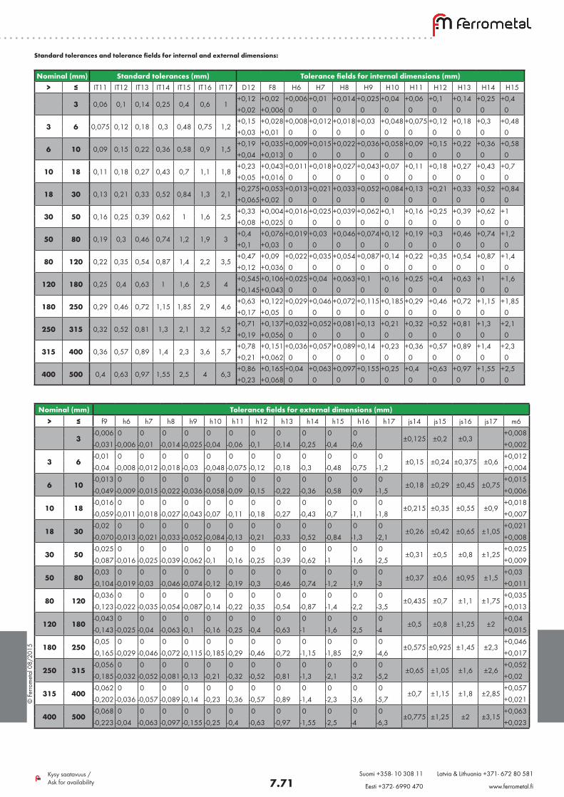
Standard tolerances and tolerance fields for internal and external dimensions:
Nominal (mm) Standard tolerances (mm) Tolerance fields for internal dimensions (mm)> ≤ IT11 IT12 IT13 IT14 IT15 IT16 IT17 D12 F8 H6 H7 H8 H9 H10 H11 H12 H13 H14 H15
3 0,06 0,1 0,14 0,25 0,4 0,6 1+0,12 +0,02 +0,006 +0,01 +0,014 +0,025 +0,04 +0,06 +0,1 +0,14 +0,25 +0,4+0,02 +0,006 0 0 0 0 0 0 0 0 0 0
3 6 0,075 0,12 0,18 0,3 0,48 0,75 1,2+0,15 +0,028 +0,008 +0,012 +0,018 +0,03 +0,048 +0,075 +0,12 +0,18 +0,3 +0,48+0,03 +0,01 0 0 0 0 0 0 0 0 0 0
6 10 0,09 0,15 0,22 0,36 0,58 0,9 1,5+0,19 +0,035 +0,009 +0,015 +0,022 +0,036 +0,058 +0,09 +0,15 +0,22 +0,36 +0,58+0,04 +0,013 0 0 0 0 0 0 0 0 0 0
10 18 0,11 0,18 0,27 0,43 0,7 1,1 1,8+0,23 +0,043 +0,011 +0,018 +0,027 +0,043 +0,07 +0,11 +0,18 +0,27 +0,43 +0,7+0,05 +0,016 0 0 0 0 0 0 0 0 0 0
18 30 0,13 0,21 0,33 0,52 0,84 1,3 2,1+0,275 +0,053 +0,013 +0,021 +0,033 +0,052 +0,084 +0,13 +0,21 +0,33 +0,52 +0,84+0,065 +0,02 0 0 0 0 0 0 0 0 0 0
30 50 0,16 0,25 0,39 0,62 1 1,6 2,5+0,33 +0,004 +0,016 +0,025 +0,039 +0,062 +0,1 +0,16 +0,25 +0,39 +0,62 +1+0,08 +0,025 0 0 0 0 0 0 0 0 0 0
50 80 0,19 0,3 0,46 0,74 1,2 1,9 3+0,4 +0,076 +0,019 +0,03 +0,046 +0,074 +0,12 +0,19 +0,3 +0,46 +0,74 +1,2+0,1 +0,03 0 0 0 0 0 0 0 0 0 0
80 120 0,22 0,35 0,54 0,87 1,4 2,2 3,5+0,47 +0,09 +0,022 +0,035 +0,054 +0,087 +0,14 +0,22 +0,35 +0,54 +0,87 +1,4+0,12 +0,036 0 0 0 0 0 0 0 0 0 0
120 180 0,25 0,4 0,63 1 1,6 2,5 4+0,545 +0,106 +0,025 +0,04 +0,063 +0,1 +0,16 +0,25 +0,4 +0,63 +1 +1,6+0,145 +0,043 0 0 0 0 0 0 0 0 0 0
180 250 0,29 0,46 0,72 1,15 1,85 2,9 4,6+0,63 +0,122 +0,029 +0,046 +0,072 +0,115 +0,185 +0,29 +0,46 +0,72 +1,15 +1,85+0,17 +0,05 0 0 0 0 0 0 0 0 0 0
250 315 0,32 0,52 0,81 1,3 2,1 3,2 5,2+0,71 +0,137 +0,032 +0,052 +0,081 +0,13 +0,21 +0,32 +0,52 +0,81 +1,3 +2,1+0,19 +0,056 0 0 0 0 0 0 0 0 0 0
315 400 0,36 0,57 0,89 1,4 2,3 3,6 5,7+0,78 +0,151 +0,036 +0,057 +0,089 +0,14 +0,23 +0,36 +0,57 +0,89 +1,4 +2,3+0,21 +0,062 0 0 0 0 0 0 0 0 0 0
400 500 0,4 0,63 0,97 1,55 2,5 4 6,3+0,86 +0,165 +0,04 +0,063 +0,097 +0,155 +0,25 +0,4 +0,63 +0,97 +1,55 +2,5+0,23 +0,068 0 0 0 0 0 0 0 0 0 0
Nominal (mm) Tolerance fields for external dimensions (mm)> ≤ f9 h6 h7 h8 h9 h10 h11 h12 h13 h14 h15 h16 h17 js14 js15 js16 js17 m6
3-0,006 0 0 0 0 0 0 0 0 0 0 0
±0,125 ±0,2 ±0,3+0,008
-0,031 -0,006 -0,01 -0,014 -0,025 -0,04 -0,06 -0,1 -0,14 -0,25 -0,4 -0,6 +0,002
3 6-0,01 0 0 0 0 0 0 0 0 0 0 0 0
±0,15 ±0,24 ±0,375 ±0,6+0,012
-0,04 -0,008 -0,012 -0,018 -0,03 -0,048 -0,075 -0,12 -0,18 -0,3 -0,48 -0,75 -1,2 +0,004
6 10-0,013 0 0 0 0 0 0 0 0 0 0 0 0
±0,18 ±0,29 ±0,45 ±0,75+0,015
-0,049 -0,009 -0,015 -0,022 -0,036 -0,058 -0,09 -0,15 -0,22 -0,36 -0,58 -0,9 -1,5 +0,006
10 18-0,016 0 0 0 0 0 0 0 0 0 0 0 0
±0,215 ±0,35 ±0,55 ±0,9+0,018
-0,059 -0,011 -0,018 -0,027 -0,043 -0,07 -0,11 -0,18 -0,27 -0,43 -0,7 -1,1 -1,8 +0,007
18 30-0,02 0 0 0 0 0 0 0 0 0 0 0 0
±0,26 ±0,42 ±0,65 ±1,05+0,021
-0,070 -0,013 -0,021 -0,033 -0,052 -0,084 -0,13 -0,21 -0,33 -0,52 -0,84 -1,3 -2,1 +0,008
30 50-0,025 0 0 0 0 0 0 0 0 0 0 0 0
±0,31 ±0,5 ±0,8 ±1,25+0,025
-0,087 -0,016 -0,025 -0,039 -0,062 -0,1 -0,16 -0,25 -0,39 -0,62 -1 -1,6 -2,5 +0,009
50 80-0,03 0 0 0 0 0 0 0 0 0 0 0 0
±0,37 ±0,6 ±0,95 ±1,5+0,03
-0,104 -0,019 -0,03 -0,046 -0,074 -0,12 -0,19 -0,3 -0,46 -0,74 -1,2 -1,9 -3 +0,011
80 120-0,036 0 0 0 0 0 0 0 0 0 0 0 0
±0,435 ±0,7 ±1,1 ±1,75+0,035
-0,123 -0,022 -0,035 -0,054 -0,087 -0,14 -0,22 -0,35 -0,54 -0,87 -1,4 -2,2 -3,5 +0,013
120 180-0,043 0 0 0 0 0 0 0 0 0 0 0 0
±0,5 ±0,8 ±1,25 ±2+0,04
-0,143 -0,025 -0,04 -0,063 -0,1 -0,16 -0,25 -0,4 -0,63 -1 -1,6 -2,5 -4 +0,015
180 250-0,05 0 0 0 0 0 0 0 0 0 0 0 0
±0,575 ±0,925 ±1,45 ±2,3+0,046
-0,165 -0,029 -0,046 -0,072 -0,115 -0,185 -0,29 -0,46 -0,72 -1,15 -1,85 -2,9 -4,6 +0,017
250 315-0,056 0 0 0 0 0 0 0 0 0 0 0 0
±0,65 ±1,05 ±1,6 ±2,6+0,052
-0,185 -0,032 -0,052 -0,081 -0,13 -0,21 -0,32 -0,52 -0,81 -1,3 -2,1 -3,2 -5,2 +0,02
315 400-0,062 0 0 0 0 0 0 0 0 0 0 0 0
±0,7 ±1,15 ±1,8 ±2,85+0,057
-0,202 -0,036 -0,057 -0,089 -0,14 -0,23 -0,36 -0,57 -0,89 -1,4 -2,3 -3,6 -5,7 +0,021
400 500-0,068 0 0 0 0 0 0 0 0 0 0 0 0
±0,775 ±1,25 ±2 ±3,15+0,063
-0,223 -0,04 -0,063 -0,097 -0,155 -0,25 -0,4 -0,63 -0,97 -1,55 -2,5 -4 -6,3 +0,023
© F
erro
met
al 0
8/20
15
7.72Kysy saatavuus / Ask for availability
Suomi +358- 10 308 11 Latvia & Lithuania +371- 672 80 581
Eesti +372- 6990 470 www.ferrometal.fi
3. Threads
Thread dimensions and accuracy of the profile are crucial when determining:• whether the fastener can be surface treated• whether the parts can be jointed together without problems• whether the thread can transmit the forces for which the components are designed
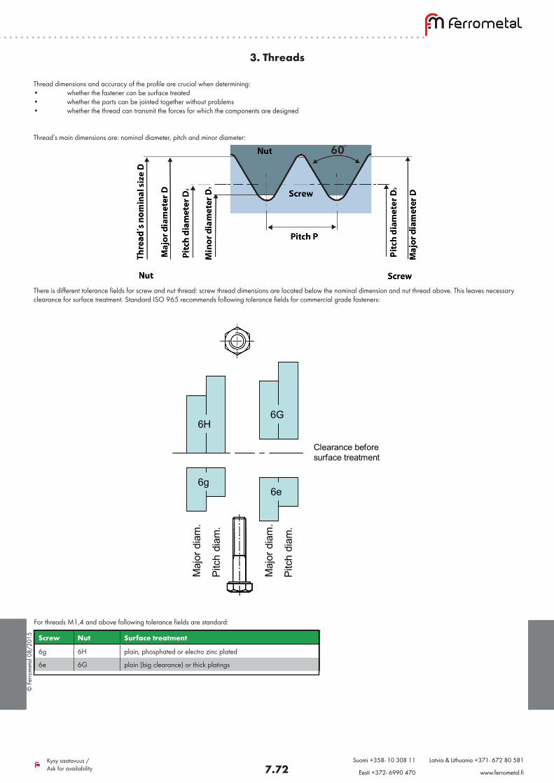
Thread’s main dimensions are: nominal diameter, pitch and minor diameter:
There is different tolerance fields for screw and nut thread: screw thread dimensions are located below the nominal dimension and nut thread above. This leaves necessary clearance for surface treatment. Standard ISO 965 recommends following tolerance fields for commercial grade fasteners:
6H
6g6e
6G
Ulk
ohal
k.
Kylk
ihal
k.
Ulk
ohal
k.
Kylk
ihal
k.
Välys ennen pintakäsittelyä
6H
6g6e
6G
Maj
ordi
am.
Pitc
hdi
am.
Maj
ordi
am.
Pitc
hdi
am.
Clearance beforesurface treatment
For threads M1,4 and above following tolerance fields are standard:
Screw Nut Surface treatment
6g 6H plain, phosphated or electro zinc plated
6e 6G plain (big clearance) or thick platings
© F
erro
met
al 0
8/20
15
7.73Kysy saatavuus / Ask for availability
Suomi +358- 10 308 11 Latvia & Lithuania +371- 672 80 581
Eesti +372- 6990 470 www.ferrometal.fi
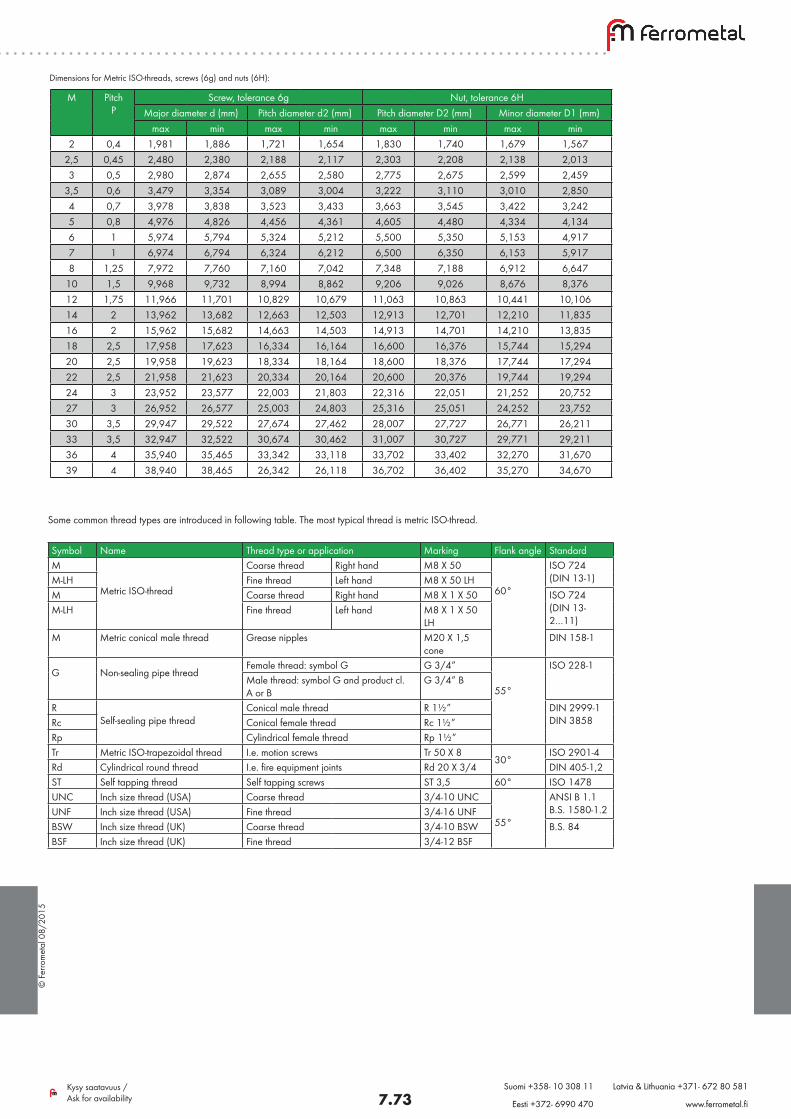
Dimensions for Metric ISO-threads, screws (6g) and nuts (6H):
Some common thread types are introduced in following table. The most typical thread is metric ISO-thread.
M Pitch P
Screw, tolerance 6g Nut, tolerance 6HMajor diameter d (mm) Pitch diameter d2 (mm) Pitch diameter D2 (mm) Minor diameter D1 (mm)
max min max min max min max min2 0,4 1,981 1,886 1,721 1,654 1,830 1,740 1,679 1,567
2,5 0,45 2,480 2,380 2,188 2,117 2,303 2,208 2,138 2,0133 0,5 2,980 2,874 2,655 2,580 2,775 2,675 2,599 2,459
3,5 0,6 3,479 3,354 3,089 3,004 3,222 3,110 3,010 2,8504 0,7 3,978 3,838 3,523 3,433 3,663 3,545 3,422 3,2425 0,8 4,976 4,826 4,456 4,361 4,605 4,480 4,334 4,1346 1 5,974 5,794 5,324 5,212 5,500 5,350 5,153 4,9177 1 6,974 6,794 6,324 6,212 6,500 6,350 6,153 5,9178 1,25 7,972 7,760 7,160 7,042 7,348 7,188 6,912 6,647
10 1,5 9,968 9,732 8,994 8,862 9,206 9,026 8,676 8,37612 1,75 11,966 11,701 10,829 10,679 11,063 10,863 10,441 10,10614 2 13,962 13,682 12,663 12,503 12,913 12,701 12,210 11,83516 2 15,962 15,682 14,663 14,503 14,913 14,701 14,210 13,83518 2,5 17,958 17,623 16,334 16,164 16,600 16,376 15,744 15,29420 2,5 19,958 19,623 18,334 18,164 18,600 18,376 17,744 17,29422 2,5 21,958 21,623 20,334 20,164 20,600 20,376 19,744 19,29424 3 23,952 23,577 22,003 21,803 22,316 22,051 21,252 20,75227 3 26,952 26,577 25,003 24,803 25,316 25,051 24,252 23,75230 3,5 29,947 29,522 27,674 27,462 28,007 27,727 26,771 26,21133 3,5 32,947 32,522 30,674 30,462 31,007 30,727 29,771 29,21136 4 35,940 35,465 33,342 33,118 33,702 33,402 32,270 31,67039 4 38,940 38,465 26,342 26,118 36,702 36,402 35,270 34,670
Symbol Name Thread type or application Marking Flank angle StandardM
Metric ISO-thread
Coarse thread Right hand M8 X 50 60°
ISO 724 (DIN 13-1)M-LH Fine thread Left hand M8 X 50 LH
M Coarse thread Right hand M8 X 1 X 50 ISO 724 (DIN 13-2…11)
M-LH Fine thread Left hand M8 X 1 X 50 LH
M Metric conical male thread Grease nipples M20 X 1,5 cone
DIN 158-1
G Non-sealing pipe threadFemale thread: symbol G G 3/4”
55°
ISO 228-1Male thread: symbol G and product cl. A or B
G 3/4” B
R Self-sealing pipe thread
Conical male thread R 1½” DIN 2999-1 DIN 3858Rc Conical female thread Rc 1½”
Rp Cylindrical female thread Rp 1½”Tr Metric ISO-trapezoidal thread I.e. motion screws Tr 50 X 8
30°ISO 2901-4
Rd Cylindrical round thread I.e. fire equipment joints Rd 20 X 3/4 DIN 405-1,2ST Self tapping thread Self tapping screws ST 3,5 60° ISO 1478UNC Inch size thread (USA) Coarse thread 3/4-10 UNC
55°
ANSI B 1.1 B.S. 1580-1.2UNF Inch size thread (USA) Fine thread 3/4-16 UNF
BSW Inch size thread (UK) Coarse thread 3/4-10 BSW B.S. 84BSF Inch size thread (UK) Fine thread 3/4-12 BSF
© F
erro
met
al 0
8/20
15
7.74Kysy saatavuus / Ask for availability
Suomi +358- 10 308 11 Latvia & Lithuania +371- 672 80 581
Eesti +372- 6990 470 www.ferrometal.fi
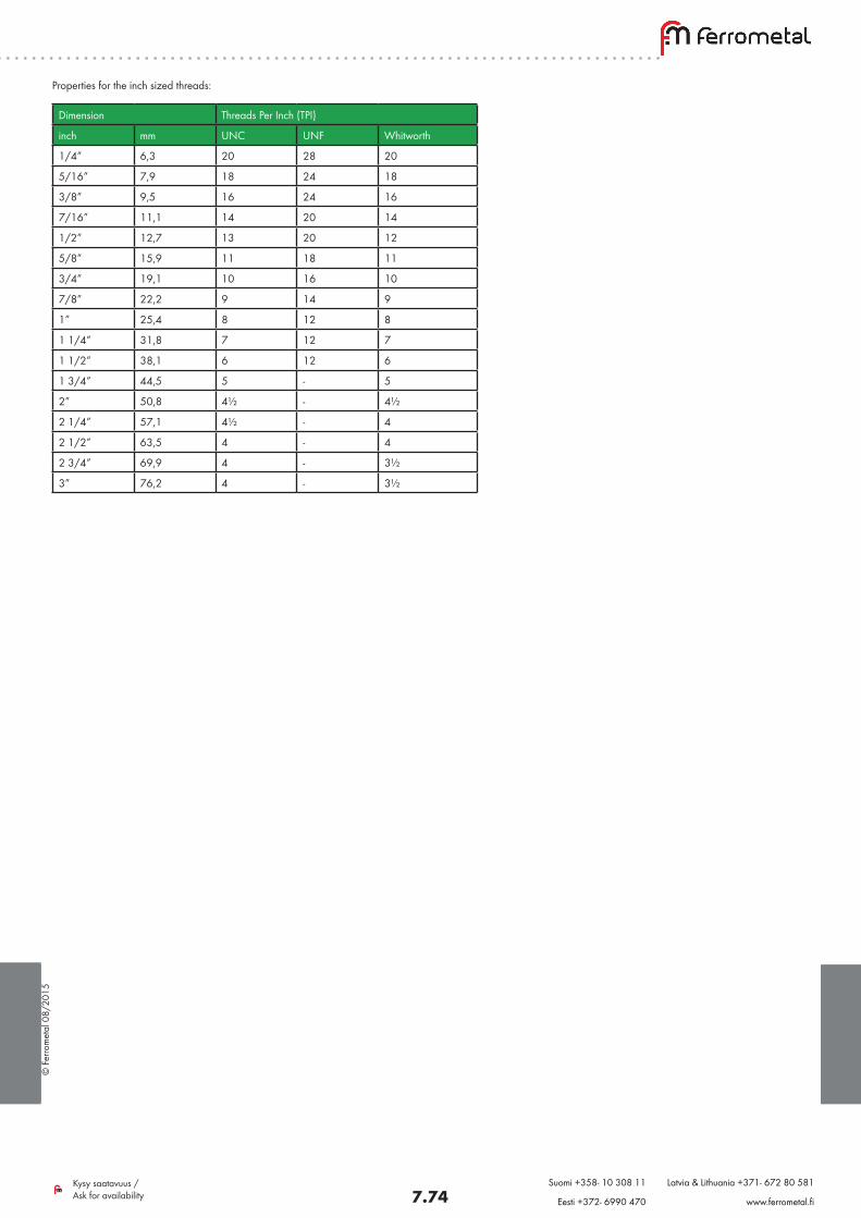
Properties for the inch sized threads:
Dimension Threads Per Inch (TPI)
inch mm UNC UNF Whitworth
1/4” 6,3 20 28 20
5/16” 7,9 18 24 18
3/8” 9,5 16 24 16
7/16” 11,1 14 20 14
1/2” 12,7 13 20 12
5/8” 15,9 11 18 11
3/4” 19,1 10 16 10
7/8” 22,2 9 14 9
1” 25,4 8 12 8
1 1/4” 31,8 7 12 7
1 1/2” 38,1 6 12 6
1 3/4” 44,5 5 - 5
2” 50,8 4½ - 4½
2 1/4” 57,1 4½ - 4
2 1/2” 63,5 4 - 4
2 3/4” 69,9 4 - 3½
3” 76,2 4 - 3½
© F
erro
met
al 0
8/20
15
7.75Kysy saatavuus / Ask for availability
Suomi +358- 10 308 11 Latvia & Lithuania +371- 672 80 581
Eesti +372- 6990 470 www.ferrometal.fi
4. Mechanical properties
Screw’s mechanical properties are presented in short in this section. Identifying these properties, it is essential to know terminology used.
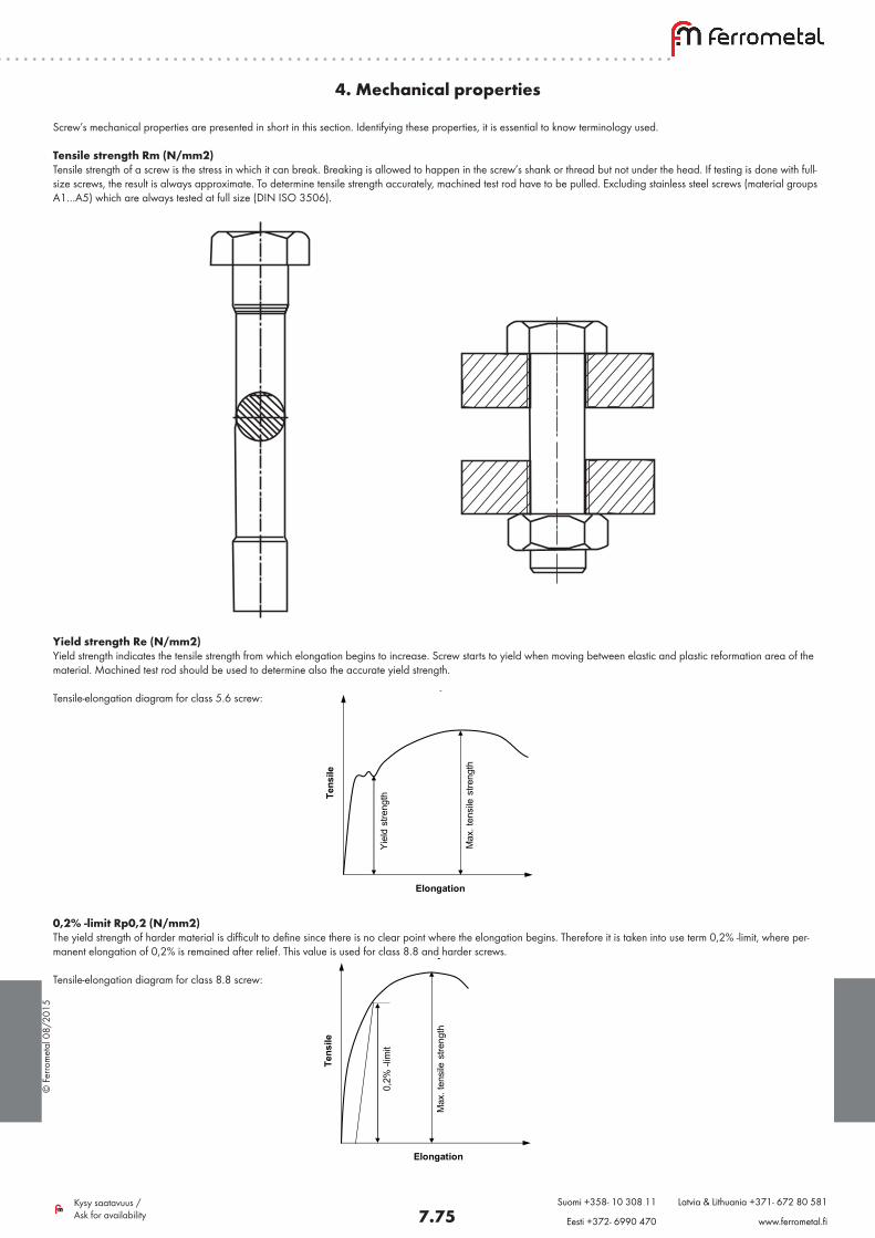
Tensile strength Rm (N/mm2)Tensile strength of a screw is the stress in which it can break. Breaking is allowed to happen in the screw’s shank or thread but not under the head. If testing is done with full-size screws, the result is always approximate. To determine tensile strength accurately, machined test rod have to be pulled. Excluding stainless steel screws (material groups A1…A5) which are always tested at full size (DIN ISO 3506).
Yield strength Re (N/mm2)Yield strength indicates the tensile strength from which elongation begins to increase. Screw starts to yield when moving between elastic and plastic reformation area of the material. Machined test rod should be used to determine also the accurate yield strength.
Tensile-elongation diagram for class 5.6 screw:Venymä
Jänn
itys
Myö
tölu
juus
Max
. vet
omur
tolu
juus
Venymä
Jänn
itys
0,2%
-raj
a
Max
. vet
omur
tolu
juus
Elongation
Tens
ile
Yiel
dst
reng
th
Max
.ten
sile
stre
ngth
Elongation
Tens
ile
0,2%
-lim
it
Max
.ten
sile
stre
ngth
0,2% -limit Rp0,2 (N/mm2)The yield strength of harder material is difficult to define since there is no clear point where the elongation begins. Therefore it is taken into use term 0,2% -limit, where per-manent elongation of 0,2% is remained after relief. This value is used for class 8.8 and harder screws.
Tensile-elongation diagram for class 8.8 screw:
Venymä
Jänn
itys
Myö
tölu
juus
Max
. vet
omur
tolu
juus
Venymä
Jänn
itys
0,2%
-raj
a
Max
. vet
omur
tolu
juus
Elongation
Tens
ile
Yiel
dst
reng
th
Max
.ten
sile
stre
ngth
Elongation
Tens
ile
0,2%
-lim
it
Max
.ten
sile
stre
ngth
© F
erro
met
al 0
8/20
15
7.76Kysy saatavuus / Ask for availability
Suomi +358- 10 308 11 Latvia & Lithuania +371- 672 80 581
Eesti +372- 6990 470 www.ferrometal.fi
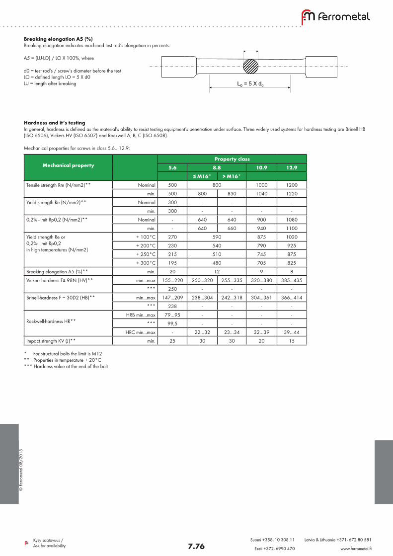
Breaking elongation A5 (%)Breaking elongation indicates machined test rod’s elongation in percents:
A5 = (LU-LO) / LO X 100%, where
d0 = test rod’s / screw’s diameter before the testLO = defined length LO = 5 X d0LU = length after breaking
d0
L0 = 5 X d0
Hardness and it’s testingIn general, hardness is defined as the material’s ability to resist testing equipment’s penetration under surface. Three widely used systems for hardness testing are Brinell HB (ISO 6506), Vickers HV (ISO 6507) and Rockwell A, B, C (ISO 6508).
Mechanical properties for screws in class 5.6…12.9:
Mechanical property
Property class5.6 8.8 10.9 12.9
≤ M16* > M16*Tensile strength Rm (N/mm2)** Nominal 500 800 1000 1200
min. 500 800 830 1040 1220
Yield strength Re (N/mm2)** Nominal 300 - - - -
min. 300 - - - -
0,2% -limit Rp0,2 (N/mm2)** Nominal - 640 640 900 1080
min. - 640 660 940 1100
Yield strength Re or 0,2%- limit Rp0,2 in high temperatures (N/mm2)
+ 100°C 270 590 875 1020
+ 200°C 230 540 790 925
+ 250°C 215 510 745 875
+ 300°C 195 480 705 825
Breaking elongation A5 (%)** min. 20 12 9 8
Vickers-hardness F≤ 98N (HV)** min...max 155...220 250...320 255...335 320...380 385...435
*** 250 - - - -
Brinell-hardness F = 30D2 (HB)** min...max 147...209 238...304 242...318 304...361 366...414
*** 238 - - - -
Rockwell-hardness HR**
HRB min...max 79…95 - - - -
*** 99,5 - - - -
HRC min...max - 22…32 23…34 32…39 39…44
Impact strength KV (J)** min. 25 30 30 20 15
* For structural bolts the limit is M12 ** Properties in temperature + 20°C *** Hardness value at the end of the bolt
© F
erro
met
al 0
8/20
15
7.77Kysy saatavuus / Ask for availability
Suomi +358- 10 308 11 Latvia & Lithuania +371- 672 80 581
Eesti +372- 6990 470 www.ferrometal.fi
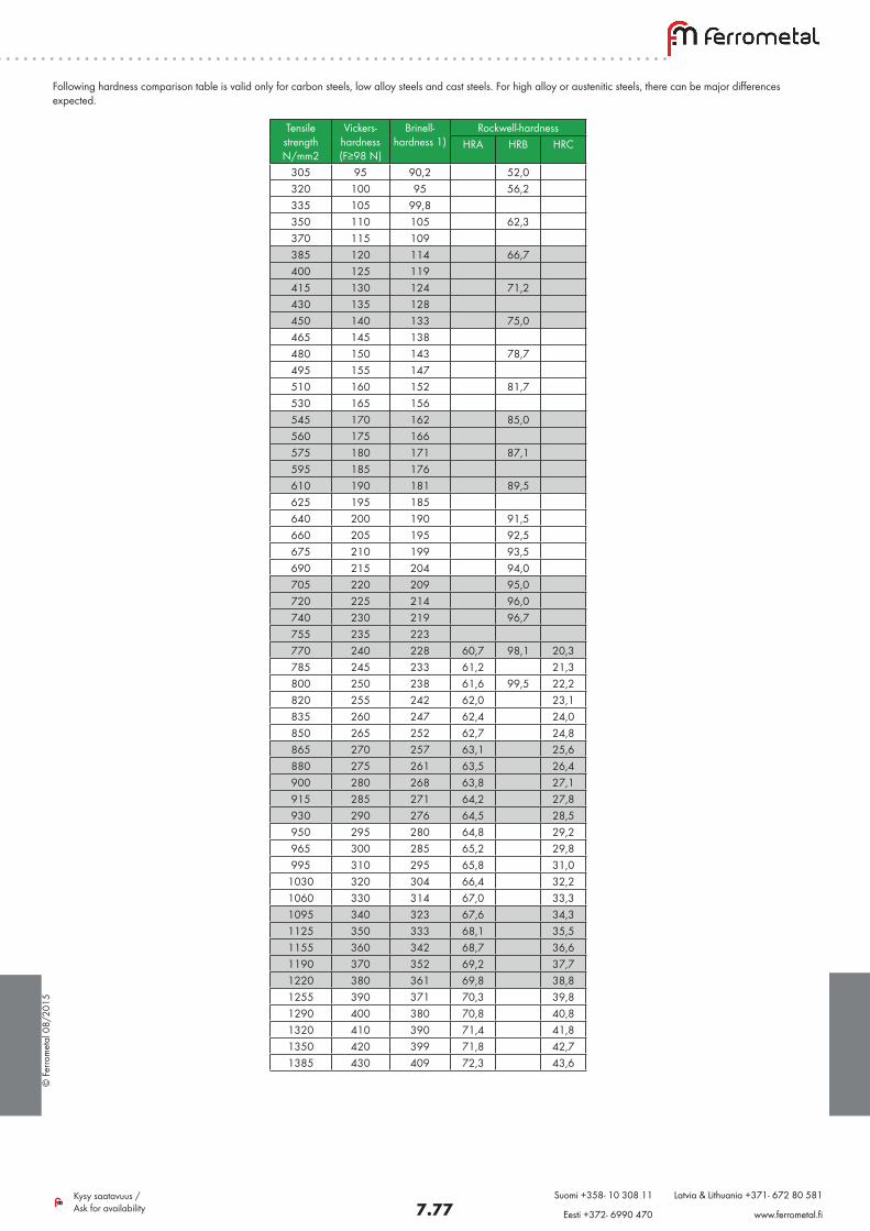
Following hardness comparison table is valid only for carbon steels, low alloy steels and cast steels. For high alloy or austenitic steels, there can be major differences expected.
Tensile strength N/mm2
Vickers- hardness (F≥98 N)
Brinell- hardness 1)
Rockwell-hardnessHRA HRB HRC
305 95 90,2 52,0320 100 95 56,2335 105 99,8350 110 105 62,3370 115 109385 120 114 66,7400 125 119415 130 124 71,2430 135 128450 140 133 75,0465 145 138480 150 143 78,7495 155 147510 160 152 81,7530 165 156545 170 162 85,0560 175 166575 180 171 87,1595 185 176610 190 181 89,5625 195 185640 200 190 91,5660 205 195 92,5675 210 199 93,5690 215 204 94,0705 220 209 95,0720 225 214 96,0740 230 219 96,7755 235 223770 240 228 60,7 98,1 20,3785 245 233 61,2 21,3800 250 238 61,6 99,5 22,2820 255 242 62,0 23,1835 260 247 62,4 24,0850 265 252 62,7 24,8865 270 257 63,1 25,6880 275 261 63,5 26,4900 280 268 63,8 27,1915 285 271 64,2 27,8930 290 276 64,5 28,5950 295 280 64,8 29,2965 300 285 65,2 29,8995 310 295 65,8 31,0
1030 320 304 66,4 32,21060 330 314 67,0 33,31095 340 323 67,6 34,31125 350 333 68,1 35,51155 360 342 68,7 36,61190 370 352 69,2 37,71220 380 361 69,8 38,81255 390 371 70,3 39,81290 400 380 70,8 40,81320 410 390 71,4 41,81350 420 399 71,8 42,71385 430 409 72,3 43,6
© F
erro
met
al 0
8/20
15
7.78Kysy saatavuus / Ask for availability
Suomi +358- 10 308 11 Latvia & Lithuania +371- 672 80 581
Eesti +372- 6990 470 www.ferrometal.fi
Material categories used in fasteners:
Carbon steel Several materials which properties as used in fasteners do not differ greatly from each other.
In exception are cold resistant materials below -50ºC and heat resistant materials over 300ºC.
Mechanical properties according to ISO 898.
Stainless steel Several materials which properties as used in ready end products differs a lot in means of corrosion resistance, heat resistance, weldability, magnetization and hardening.
Mechanical properties according to ISO 3506.
Non-iron metals, e.g. aluminium and copper
Material codes, mechanical properties, testing methods and values and markings according to standards ISO 8839 / EN 28 839.
Other metals, e.g. brass and titanium
No standards. In some cases, mechanical properties of carbon steel screws can be applied.
Plastic No standards
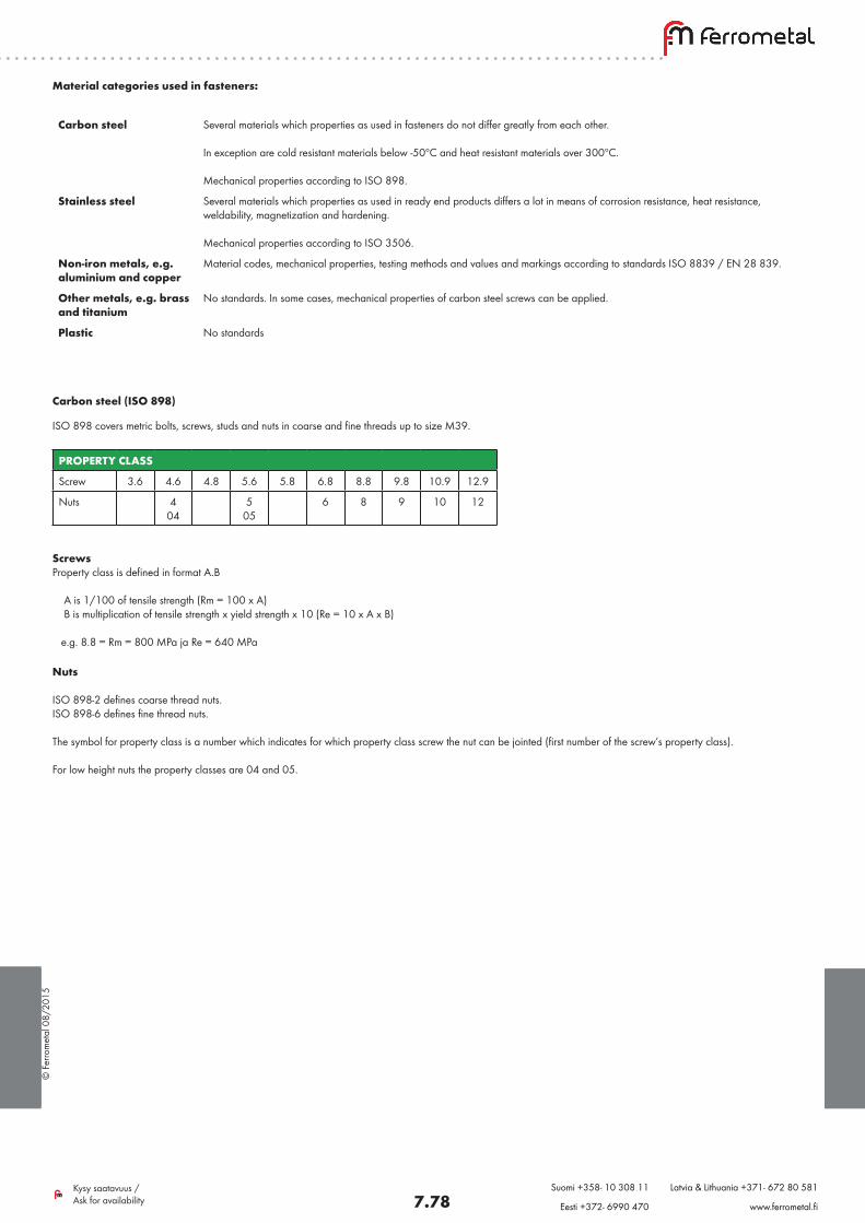
Carbon steel (ISO 898)
ISO 898 covers metric bolts, screws, studs and nuts in coarse and fine threads up to size M39.
PROPERTY CLASS
Screw 3.6 4.6 4.8 5.6 5.8 6.8 8.8 9.8 10.9 12.9
Nuts 4 04
5 05
6 8 9 10 12
ScrewsProperty class is defined in format A.B
A is 1/100 of tensile strength (Rm = 100 x A) B is multiplication of tensile strength x yield strength x 10 (Re = 10 x A x B)
e.g. 8.8 = Rm = 800 MPa ja Re = 640 MPa
Nuts
ISO 898-2 defines coarse thread nuts.ISO 898-6 defines fine thread nuts.
The symbol for property class is a number which indicates for which property class screw the nut can be jointed (first number of the screw’s property class).
For low height nuts the property classes are 04 and 05.
© F
erro
met
al 0
8/20
15
7.79Kysy saatavuus / Ask for availability
Suomi +358- 10 308 11 Latvia & Lithuania +371- 672 80 581
Eesti +372- 6990 470 www.ferrometal.fi
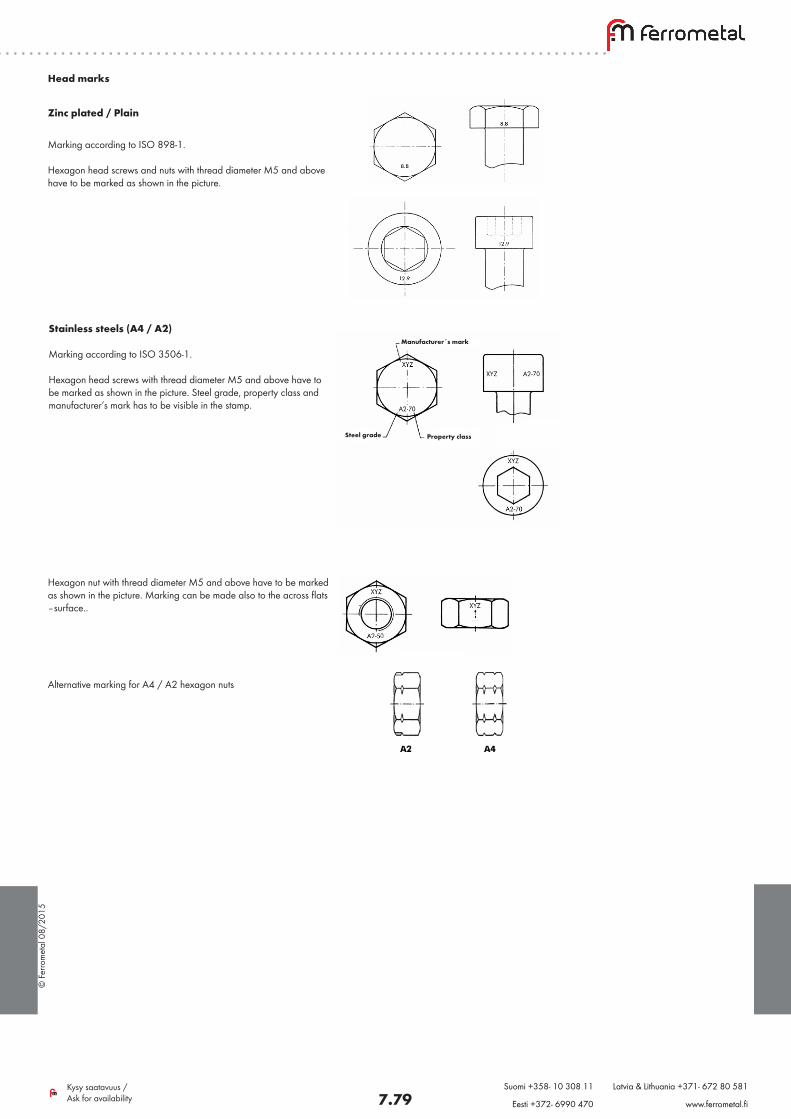
Zinc plated / Plain
Marking according to ISO 898-1.
Hexagon head screws and nuts with thread diameter M5 and above have to be marked as shown in the picture.
Head marks
Stainless steels (A4 / A2)
Marking according to ISO 3506-1.
Hexagon head screws with thread diameter M5 and above have to be marked as shown in the picture. Steel grade, property class and manufacturer’s mark has to be visible in the stamp.
Manufacturer´s mark
Steel grade Property class
Hexagon nut with thread diameter M5 and above have to be marked as shown in the picture. Marking can be made also to the across flats –surface..
Alternative marking for A4 / A2 hexagon nuts
© F
erro
met
al 0
8/20
15
7.80Kysy saatavuus / Ask for availability
Suomi +358- 10 308 11 Latvia & Lithuania +371- 672 80 581
Eesti +372- 6990 470 www.ferrometal.fi
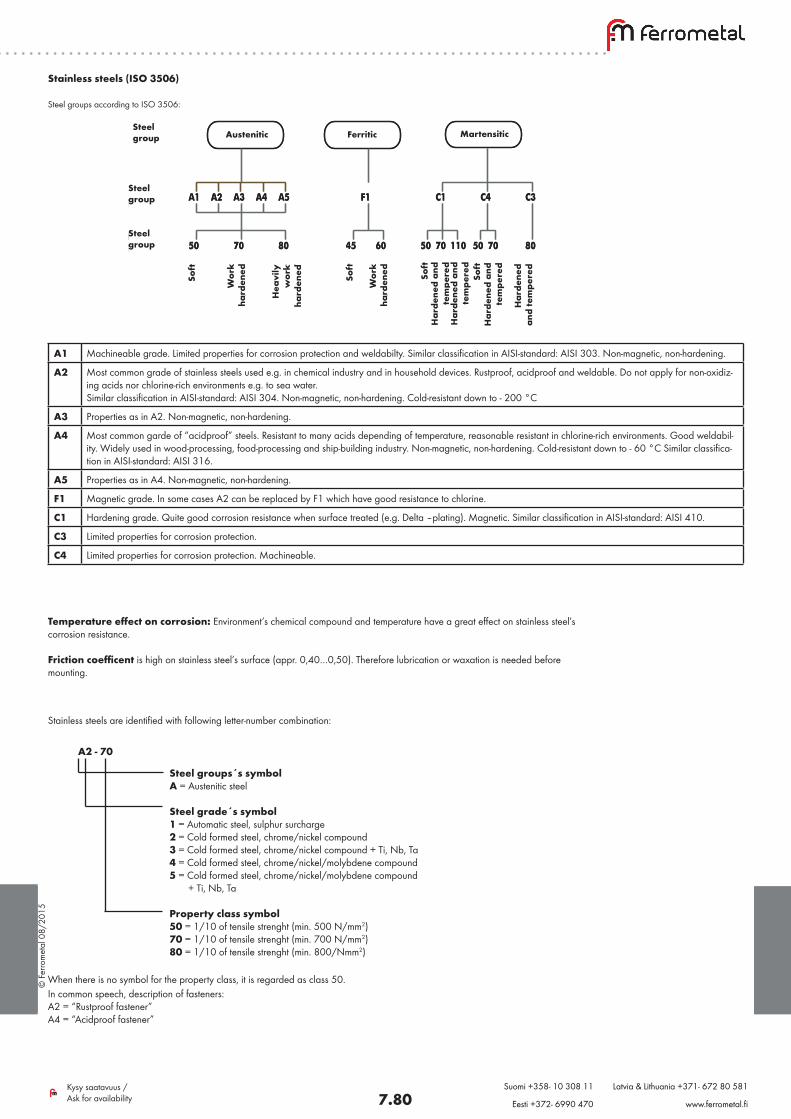
Stainless steels (ISO 3506)
Steel groups according to ISO 3506:
A1 Machineable grade. Limited properties for corrosion protection and weldabilty. Similar classification in AISI-standard: AISI 303. Non-magnetic, non-hardening.
A2 Most common grade of stainless steels used e.g. in chemical industry and in household devices. Rustproof, acidproof and weldable. Do not apply for non-oxidiz-ing acids nor chlorine-rich environments e.g. to sea water. Similar classification in AISI-standard: AISI 304. Non-magnetic, non-hardening. Cold-resistant down to - 200 °C
A3 Properties as in A2. Non-magnetic, non-hardening.
A4 Most common garde of “acidproof” steels. Resistant to many acids depending of temperature, reasonable resistant in chlorine-rich environments. Good weldabil-ity. Widely used in wood-processing, food-processing and ship-building industry. Non-magnetic, non-hardening. Cold-resistant down to - 60 °C Similar classifica-tion in AISI-standard: AISI 316.
A5 Properties as in A4. Non-magnetic, non-hardening.
F1 Magnetic grade. In some cases A2 can be replaced by F1 which have good resistance to chlorine.
C1 Hardening grade. Quite good corrosion resistance when surface treated (e.g. Delta –plating). Magnetic. Similar classification in AISI-standard: AISI 410.
C3 Limited properties for corrosion protection.
C4 Limited properties for corrosion protection. Machineable.
Temperature effect on corrosion: Environment’s chemical compound and temperature have a great effect on stainless steel’s corrosion resistance.
Friction coefficent is high on stainless steel’s surface (appr. 0,40…0,50). Therefore lubrication or waxation is needed before mounting.
Austeniittinen Ferriittinen Martensiittinen
A1 A2 A3 A4 A5 F1 C1 C4 C3
50 70 80 45 60 50 70 110 50 70 80
Pehm
eä
Muokkaus-
lujitt
unut
Voim
akkaast
im
uokkaus-
lujitt
unut
Pehm
eä
Muokkaus-
lujitt
unut
Pehm
eä
Nuorr
ute
ttu
Nuorr
ute
ttu
Pehm
eä
Nuorr
ute
ttu
Nuorr
ute
ttu
TERÄS-RYHMÄ
TERÄS-LUOKKA
LUJUUS-LUOKKA
Austeniittinen Ferriittinen Martensiittinen
A1 A2 A3 A4 A5 F1 C1 C4 C3
50 70 80 45 60 50 70 110 50 70 80
Pehm
eä
Muokkaus-
lujitt
unut
Voim
akkaast
im
uokkaus-
lujitt
unut
Pehm
eä
Muokkaus-
lujitt
unut
Pehm
eä
Nuorr
ute
ttu
Nuorr
ute
ttu
Pehm
eä
Nuorr
ute
ttu
Nuorr
ute
ttu
TERÄS-LUOKKA
LUJUUS-LUOKKA
Steelgroup
Steelgroup
Steelgroup
Austenitic Ferritic Martensitic
Soft
Wor
kha
rden
ed
Hea
vily
w
ork
hard
ened So
ft
Wor
kha
rden
ed Soft
Soft
Har
dene
d an
d te
mpe
red
Har
dene
d an
d te
mpe
red
Har
dene
d an
d te
mpe
red
Har
dene
d an
d te
mpe
red
Stainless steels are identified with following letter-number combination:
A2 - 70
Steel groups´s symbolA = Austenitic steel
Steel grade´s symbol1 = Automatic steel, sulphur surcharge2 = Cold formed steel, chrome/nickel compound3 = Cold formed steel, chrome/nickel compound + Ti, Nb, Ta4 = Cold formed steel, chrome/nickel/molybdene compound 5 = Cold formed steel, chrome/nickel/molybdene compound + Ti, Nb, Ta
Property class symbol50 = 1/10 of tensile strenght (min. 500 N/mm2)70 = 1/10 of tensile strenght (min. 700 N/mm2)80 = 1/10 of tensile strenght (min. 800/Nmm2)
When there is no symbol for the property class, it is regarded as class 50.In common speech, description of fasteners:A2 = “Rustproof fastener”A4 = “Acidproof fastener”
© F
erro
met
al 0
8/20
15
7.81Kysy saatavuus / Ask for availability
Suomi +358- 10 308 11 Latvia & Lithuania +371- 672 80 581
Eesti +372- 6990 470 www.ferrometal.fi
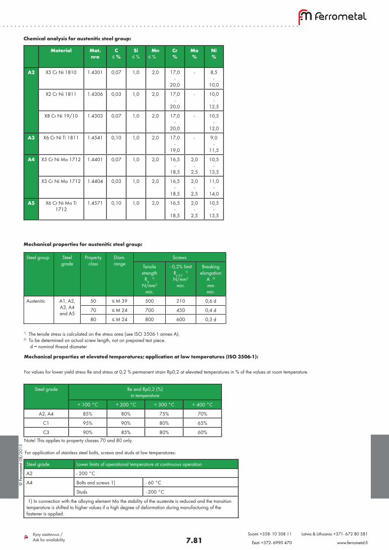
Material Mat.nro
C≤ %
Si≤ %
Mn≤ %
Cr%
Mo%
Ni%
A2 X5 Cr Ni 1810 1.4301 0,07 1,0 2,0 17,0-
20,0
- 8,5-
10,0
X2 Cr Ni 1811 1.4306 0,03 1,0 2,0 17,0-
20,0
- 10,0-
12,5
X8 Cr Ni 19/10 1.4303 0,07 1,0 2,0 17,0-
20,0
- 10,5-
12,0
A3 X6 Cr Ni Ti 1811 1.4541 0,10 1,0 2,0 17,0-
19,0
- 9,0-
11,5
A4 X5 Cr Ni Mo 1712 1.4401 0,07 1,0 2,0 16,5-
18,5
2,0-
2,5
10,5-
13,5
X3 Cr Ni Mo 1712 1.4404 0,03 1,0 2,0 16,5-
18,5
2,0-
2,5
11,0-
14,0
A5 X6 Cr Ni Mo Ti 1712
1.4571 0,10 1,0 2,0 16,5-
18,5
2,0-
2,5
10,5-
13,5
Chemical analysis for austenitic steel group:
Mechanical properties for austenitic steel group:
Steel group Steel grade
Property class
Diam. range
Screws
Tensile strength
Rm 1)
N/mm2
min.
- 0,2% limitRp 0,2
1)
N/mm2
min.
Breaking elongation
A 2)
mmmin.
Austenitic A1, A2, A3, A4 and A5
50 ≤ M 39 500 210 0,6 d
70 ≤ M 24 700 450 0,4 d
80 ≤ M 24 800 600 0,3 d
1) The tensile stress is calculated on the stress area (see ISO 3506-1 annex A). 2) To be determined on actual screw length, not on prepared test piece. d = nominal thread diameter
Mechanical properties at elevated temperatures; application at low temperatures (ISO 3506-1):
For values for lower yield stress Re and stress at 0,2 % permanent strain Rp0,2 at elevated temperatures in % of the values at room temperature.
For application of stainless steel bolts, screws and studs at low temperatures:
Steel grade Re and Rp0,2 (%) in temperature
+ 100 °C + 200 °C + 300 °C + 400 °C
A2, A4 85% 80% 75% 70%
C1 95% 90% 80% 65%
C3 90% 85% 80% 60%Note! This applies to property classes 70 and 80 only.
Steel grade Lower limits of operational temperature at continuous operation
A2 - 200 °C
A4 Bolts and screws 1) - 60 °C
Studs - 200 °C
1) In connection with the alloying element Mo the stability of the austenite is reduced and the transition temperature is shifted to higher values if a high degree of deformation during manufacturing of the fastener is applied.
© F
erro
met
al 0
8/20
15
7.82Kysy saatavuus / Ask for availability
Suomi +358- 10 308 11 Latvia & Lithuania +371- 672 80 581
Eesti +372- 6990 470 www.ferrometal.fi
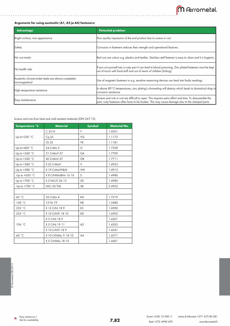
Arguments for using austenitic (A1, A2 ja A4) fasteners:
Advantage Potential problem
Bright surface, nice appearance Poor quality impression of the end product due to screws in rust.
Safety Corrosion in fasteners reduces their strength and operational features.
No rust marks Red rust can colour e.g. plastics and textiles. Stainless stell fastener is easy to clean and it is hygienic.
No health risks If you cut yourself into a rusty part it can lead to blood poisoning. Zinc plated fasteners must be kept out of touch with food stuff and out of reach of children (licking).
Austenitic chrome-nickel steels are almost completely non-magnetical Use of magnetic fasteners in e.g. sensitive measuring devices can lead into faulty readings.
High temperature resistance In above 80°C temperatures, zinc plating’s chromating will destroy which leads to dramatical drop in corrosion resistance.
Easy maintenance Screws and nuts in rust are difficult to open. This requires extra effort and time. To disassemble the joint, rusty fasteners often have to be broken. This may cause damage also to the clamped parts.
Screws and nuts from heat and cold resistant materials (DIN 267-13):
Temperature ˚C Material Symbol Material No.
C 35 N Y 1.0501
Up to+350 ˚C Cq 35 YQ 1.1172
Ck 35 YK 1.1181
Up to+400 ˚C 24 CrMo 5 G 1.7258
Up to +540 ˚C 21 CrMoV 57 GA 1.7709
Up to +540 ˚C 40 CrMoV 47 GB 1.7711
Up to +580 ˚C X 22 CrMoV V 1.4923
Up to +580 ˚C X 19 CrMoVNbN VW 1.4913
Up to +650 ˚C X 8 CrNiMoBNv 16 16 S 1.4986
Up to +700 ˚C X 5 NiCrTi 26 15 SD 1.4980
Up to +700 ˚C NiCr 20 TiAl SB 2.4952
-65 ˚C 26 CrMo 4 KA 1.7219
-140 ˚C 12 Ni 19 KB 1.5680
-253 ˚C X 12 CrNi 18 9 KC 1.6900
-253 ˚C X 10 CrNiTi 18 10 KD 1.6903
X 5 CrNi 18 9 1.4301
-196 ˚C X 5 CrNi 19 11 A2 1.4303
X 10 CrNiTi 18 9 1.4541
-60 ˚C X 10 CrNiMo Ti 18 10 A4 1.4571
X 5 CrNiMo 18 10 1.4401
© F
erro
met
al 0
8/20
15
7.83Kysy saatavuus / Ask for availability
Suomi +358- 10 308 11 Latvia & Lithuania +371- 672 80 581
Eesti +372- 6990 470 www.ferrometal.fi
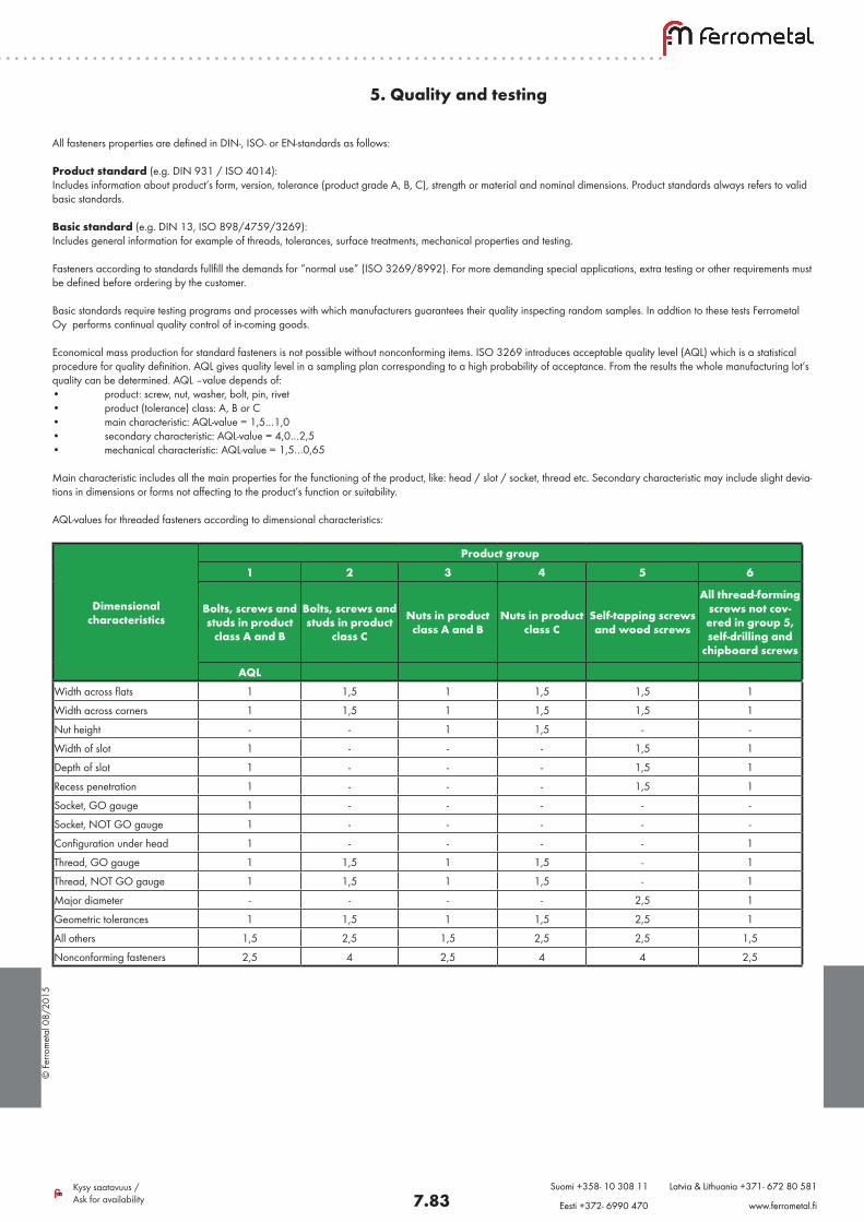
5. Quality and testing
All fasteners properties are defined in DIN-, ISO- or EN-standards as follows:
Product standard (e.g. DIN 931 / ISO 4014):Includes information about product’s form, version, tolerance (product grade A, B, C), strength or material and nominal dimensions. Product standards always refers to valid basic standards.
Basic standard (e.g. DIN 13, ISO 898/4759/3269):Includes general information for example of threads, tolerances, surface treatments, mechanical properties and testing.
Fasteners according to standards fullfill the demands for ”normal use” (ISO 3269/8992). For more demanding special applications, extra testing or other requirements must be defined before ordering by the customer.
Basic standards require testing programs and processes with which manufacturers guarantees their quality inspecting random samples. In addtion to these tests Ferrometal Oy performs continual quality control of in-coming goods.
Economical mass production for standard fasteners is not possible without nonconforming items. ISO 3269 introduces acceptable quality level (AQL) which is a statistical procedure for quality definition. AQL gives quality level in a sampling plan corresponding to a high probability of acceptance. From the results the whole manufacturing lot’s quality can be determined. AQL –value depends of: • product: screw, nut, washer, bolt, pin, rivet• product (tolerance) class: A, B or C• main characteristic: AQL-value = 1,5…1,0• secondary characteristic: AQL-value = 4,0…2,5• mechanical characteristic: AQL-value = 1,5…0,65
Main characteristic includes all the main properties for the functioning of the product, like: head / slot / socket, thread etc. Secondary characteristic may include slight devia-tions in dimensions or forms not affecting to the product’s function or suitability. AQL-values for threaded fasteners according to dimensional characteristics:
Dimensional characteristics
Product group1 2 3 4 5 6
Bolts, screws and studs in product
class A and B
Bolts, screws and studs in product
class C
Nuts in product class A and B
Nuts in product class C
Self-tapping screws and wood screws
All thread-forming screws not cov-ered in group 5, self-drilling and
chipboard screws
AQLWidth across flats 1 1,5 1 1,5 1,5 1
Width across corners 1 1,5 1 1,5 1,5 1
Nut height - - 1 1,5 - -
Width of slot 1 - - - 1,5 1
Depth of slot 1 - - - 1,5 1
Recess penetration 1 - - - 1,5 1
Socket, GO gauge 1 - - - - -
Socket, NOT GO gauge 1 - - - - -
Configuration under head 1 - - - - 1
Thread, GO gauge 1 1,5 1 1,5 - 1
Thread, NOT GO gauge 1 1,5 1 1,5 - 1
Major diameter - - - - 2,5 1
Geometric tolerances 1 1,5 1 1,5 2,5 1
All others 1,5 2,5 1,5 2,5 2,5 1,5
Nonconforming fasteners 2,5 4 2,5 4 4 2,5
© F
erro
met
al 0
8/20
15
7.84Kysy saatavuus / Ask for availability
Suomi +358- 10 308 11 Latvia & Lithuania +371- 672 80 581
Eesti +372- 6990 470 www.ferrometal.fi
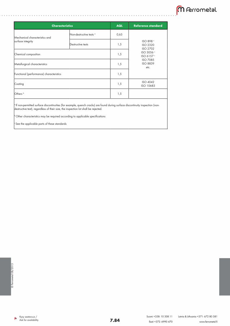
Characteristics AQL Reference standard
Mechanical characteristics and surface integrity
Non-destructive tests a 0,65
ISO 898 c ISO 2320 ISO 2702 ISO 3056 c
ISO 6157 c
ISO 7085 ISO 8839
etc.
Destructive tests 1,5
Chemical composition 1,5
Metallurgical characteristics 1,5
Functional (performance) characteristics 1,5
Coating 1,5 ISO 4042 ISO 10683
Others b 1,5
a If non-permitted surface discontinuities (for example, quench cracks) are found during surface discontinuity inspection (non-destructive test), regardless of their size, the inspection lot shall be rejected. b Other characteristics may be required according to applicable specifications c See the applicable parts of these standards
© F
erro
met
al 0
8/20
15
7.85Kysy saatavuus / Ask for availability
Suomi +358- 10 308 11 Latvia & Lithuania +371- 672 80 581
Eesti +372- 6990 470 www.ferrometal.fi
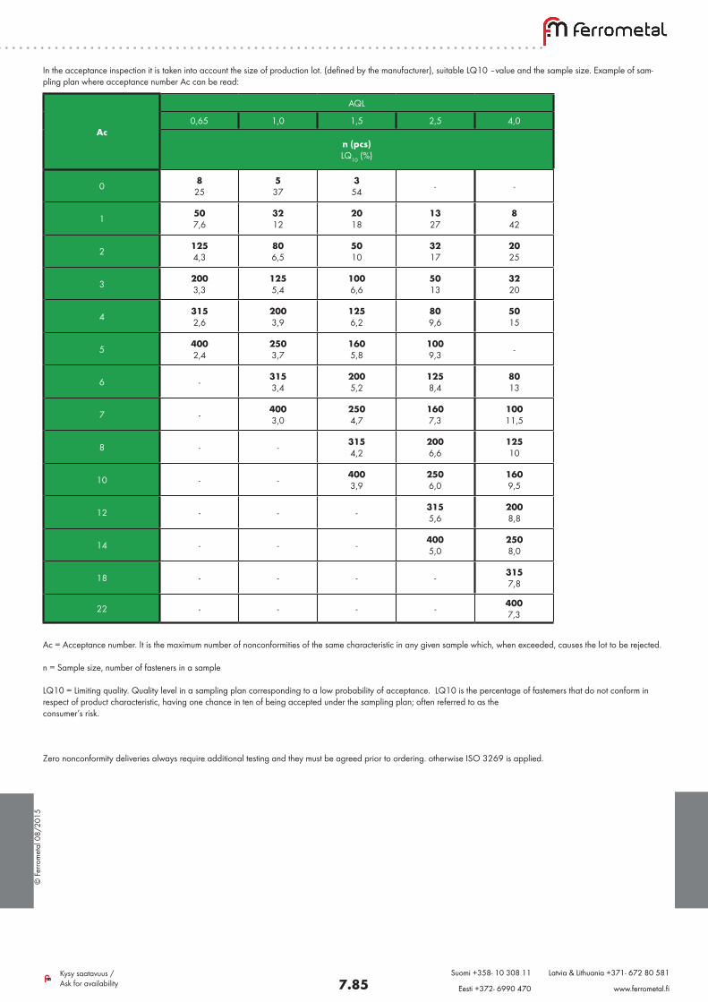
In the acceptance inspection it is taken into account the size of production lot. (defined by the manufacturer), suitable LQ10 –value and the sample size. Example of sam-pling plan where acceptance number Ac can be read:
Ac = Acceptance number. It is the maximum number of nonconformities of the same characteristic in any given sample which, when exceeded, causes the lot to be rejected.
n = Sample size, number of fasteners in a sample
LQ10 = Limiting quality. Quality level in a sampling plan corresponding to a low probability of acceptance. LQ10 is the percentage of fastemers that do not conform in respect of product characteristic, having one chance in ten of being accepted under the sampling plan; often referred to as the consumer’s risk.
Ac
AQL
0,65 1,0 1,5 2,5 4,0
n (pcs) LQ10 (%)
0 8 25
5 37
3 54 - -
1 50 7,6
32 12
20 18
13 27
8 42
2 125 4,3
80 6,5
50 10
32 17
20 25
3 200 3,3
125 5,4
100 6,6
50 13
32 20
4 315 2,6
200 3,9
125 6,2
80 9,6
50 15
5 400 2,4
250 3,7
160 5,8
100 9,3 -
6 - 315 3,4
200 5,2
125 8,4
80 13
7 - 400 3,0
250 4,7
160 7,3
100 11,5
8 - - 315 4,2
200 6,6
125 10
10 - - 400 3,9
250 6,0
160 9,5
12 - - - 315 5,6
200 8,8
14 - - - 400 5,0
250 8,0
18 - - - - 315 7,8
22 - - - - 400 7,3
Zero nonconformity deliveries always require additional testing and they must be agreed prior to ordering. otherwise ISO 3269 is applied.
© F
erro
met
al 0
8/20
15
7.86Kysy saatavuus / Ask for availability
Suomi +358- 10 308 11 Latvia & Lithuania +371- 672 80 581
Eesti +372- 6990 470 www.ferrometal.fi
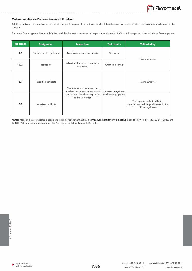
Material certificates, Pressure Equipment Directive.
NOTE! None of these certificates is capable to fullfill the requirements set by the Pressure Equipment Directive (PED; EN 13445, EN 12962, EN 12953, EN 13488). Ask for more information about the PED requirements from Ferrometal Oy sales.
Additional tests can be carried out accordance to the special request of the customer. Results of these tests are documentated into a certificate which is delivered to the customer.
For certain fastener groups, Ferrometal Oy has available the most commonly used Inspection certificate 3.1B. Our catalogue prices do not include certficate expenses.
EN 10204 Designation Inspection Test results Validated by
2.1 Declaration of compliance No determination of test results No results
The manufacturer
2.2 Test report Indication of results of non-specific insopection Chemical analysis
3.1 Inspection certificate
The test unit and the tests to be carried out are defined by the product
specification, the official regulation and/or the order
Chemical analysis and mechanical properties
The manufacturer
3.2 Inspection certificateThe inspector authorized by the
manufacturer and the purchaser or by the official regulations
© F
erro
met
al 0
8/20
15
7.87Kysy saatavuus / Ask for availability
Suomi +358- 10 308 11 Latvia & Lithuania +371- 672 80 581
Eesti +372- 6990 470 www.ferrometal.fi
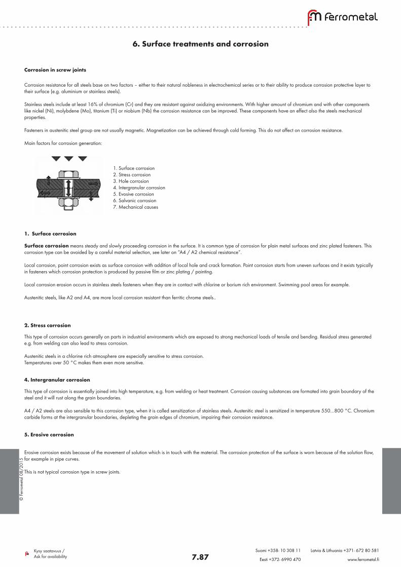
Corrosion in screw joints
1. Surface corrosion2. Stress corrosion3. Hole corrosion4. Intergranular corrosion5. Evosive corrosion6. Salvanic corrosion7. Mechanical causes
Corrosion resistance for all steels base on two factors – either to their natural nobleness in electrochemical series or to their ability to produce corrosion protective layer to their surface (e.g. aluminium or stainless steels).
Stainless steels include at least 16% of chromium (Cr) and they are resistant against oxidizing environments. With higher amount of chromium and with other components like nickel (Ni), molybdene (Mo), titanium (Ti) or niobium (Nb) the corrosion resistance can be improved. These components have an effect also the steels mechanical properties.
Fasteners in austenitic steel group are not usually magnetic. Magnetization can be achieved through cold forming. This do not affect on corrosion resistance.
Main factors for corrosion generation:
1. Surface corrosion
Surface corrosion means steady and slowly proceeding corrosion in the surface. It is common type of corrosion for plain metal surfaces and zinc plated fasteners. This corrosion type can be avoided by a careful material selection, see later on “A4 / A2 chemical resistance”.
Local corrosion, point corrosion exists as surface corrosion with addition of local hole and crack formation. Point corrosion starts from uneven surfaces and it exists typically in fasteners which corrosion protection is produced by passive film or zinc plating / painting.
Local corrosion erosion occurs in stainless steels fasteners when they are in contact with chlorine or borium rich environment. Swimming pool areas for example.
Austenitic steels, like A2 and A4, are more local corrosion resistant than ferritic chrome steels..
6. Surface treatments and corrosion
2. Stress corrosion
This type of corrosion occurs generally on parts in industrial environments which are exposed to strong mechanical loads of tensile and bending. Residual stress generated e.g. from welding can also lead to stress corrosion.
Austenitic steels in a chlorine rich atmosphere are especially sensitive to stress corrosion. Temperatures over 50 °C makes them even more sensitive.
4. Intergranular corrosion
This type of corrosion is essentially joined into high temperature, e.g. from welding or heat treatment. Corrosion causing substances are formated into grain boundary of the steel and it will rust along the grain boundaries.
A4 / A2 steels are also sensible to this corrosion type, when it is called sensitization of stainless steels. Austenitic steel is sensitized in temperature 550…800 °C. Chromium carbide forms at the intergranular boundaries, depleting the grain edges of chromium, impairing their corrosion resistance.
5. Erosive corrosion
Erosive corrosion exists because of the movement of solution which is in touch with the material. The corrosion protection of the surface is worn because of the solution flow, for example in pipe curves.
This is not typical corrosion type in screw joints.
© F
erro
met
al 0
8/20
15
7.88Kysy saatavuus / Ask for availability
Suomi +358- 10 308 11 Latvia & Lithuania +371- 672 80 581
Eesti +372- 6990 470 www.ferrometal.fi
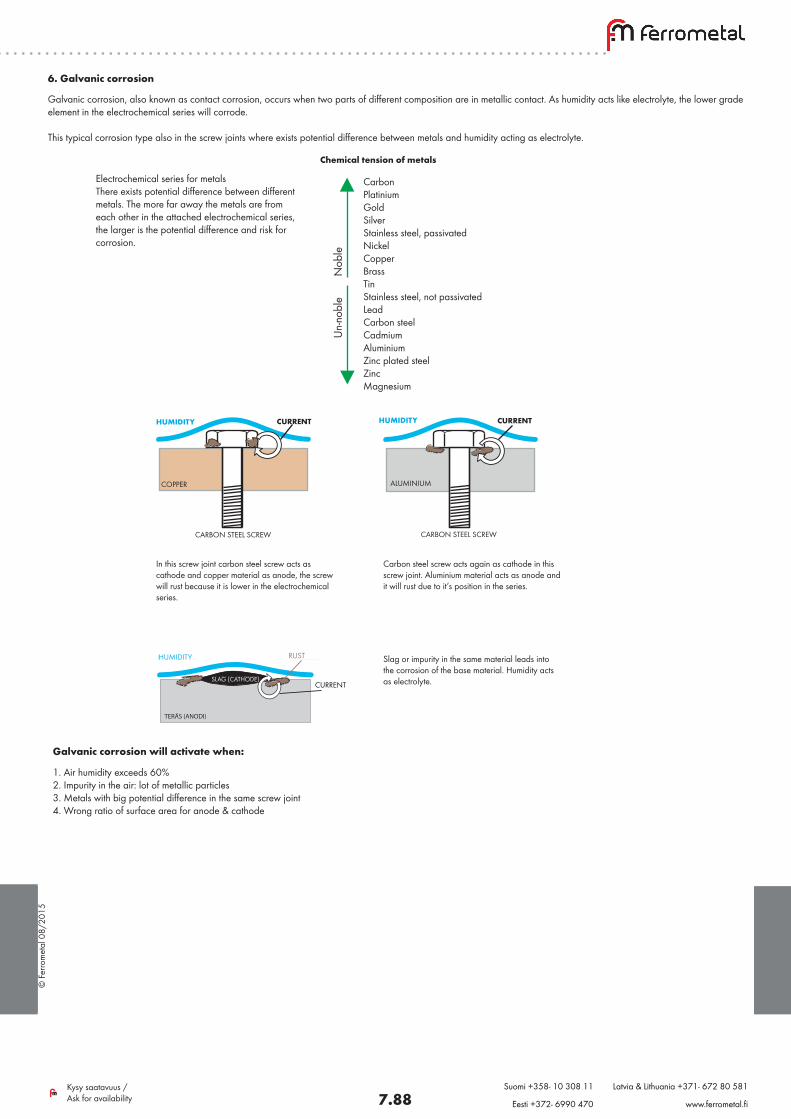
6. Galvanic corrosion
Galvanic corrosion, also known as contact corrosion, occurs when two parts of different composition are in metallic contact. As humidity acts like electrolyte, the lower grade element in the electrochemical series will corrode.
This typical corrosion type also in the screw joints where exists potential difference between metals and humidity acting as electrolyte.
Electrochemical series for metalsThere exists potential difference between different metals. The more far away the metals are from each other in the attached electrochemical series, the larger is the potential difference and risk for corrosion.
Chemical tension of metals
CarbonPlatinium GoldSilver Stainless steel, passivated NickelCopper Brass TinStainless steel, not passivatedLeadCarbon steelCadmiumAluminiumZinc plated steelZincMagnesium
Un-
nobl
e
N
oble
TERÄS (ANODI)
KOSTEUSKALVO (ELEKTROLYYTTI)
KUONA (KATODI)
RUOSTETTA
VIRTA
In this screw joint carbon steel screw acts as cathode and copper material as anode, the screw will rust because it is lower in the electrochemical series.
Carbon steel screw acts again as cathode in this screw joint. Aluminium material acts as anode and it will rust due to it’s position in the series.
Slag or impurity in the same material leads into the corrosion of the base material. Humidity acts as electrolyte.
HUMIDITY CURRENT
COPPER
CARBON STEEL SCREW
HUMIDITY
CARBON STEEL SCREW
ALUMINIUM
HUMIDITY RUST
CURRENTSLAG (CATHODE)
CURRENT
Galvanic corrosion will activate when:
1. Air humidity exceeds 60%2. Impurity in the air: lot of metallic particles3. Metals with big potential difference in the same screw joint4. Wrong ratio of surface area for anode & cathode
© F
erro
met
al 0
8/20
15
7.89Kysy saatavuus / Ask for availability
Suomi +358- 10 308 11 Latvia & Lithuania +371- 672 80 581
Eesti +372- 6990 470 www.ferrometal.fi
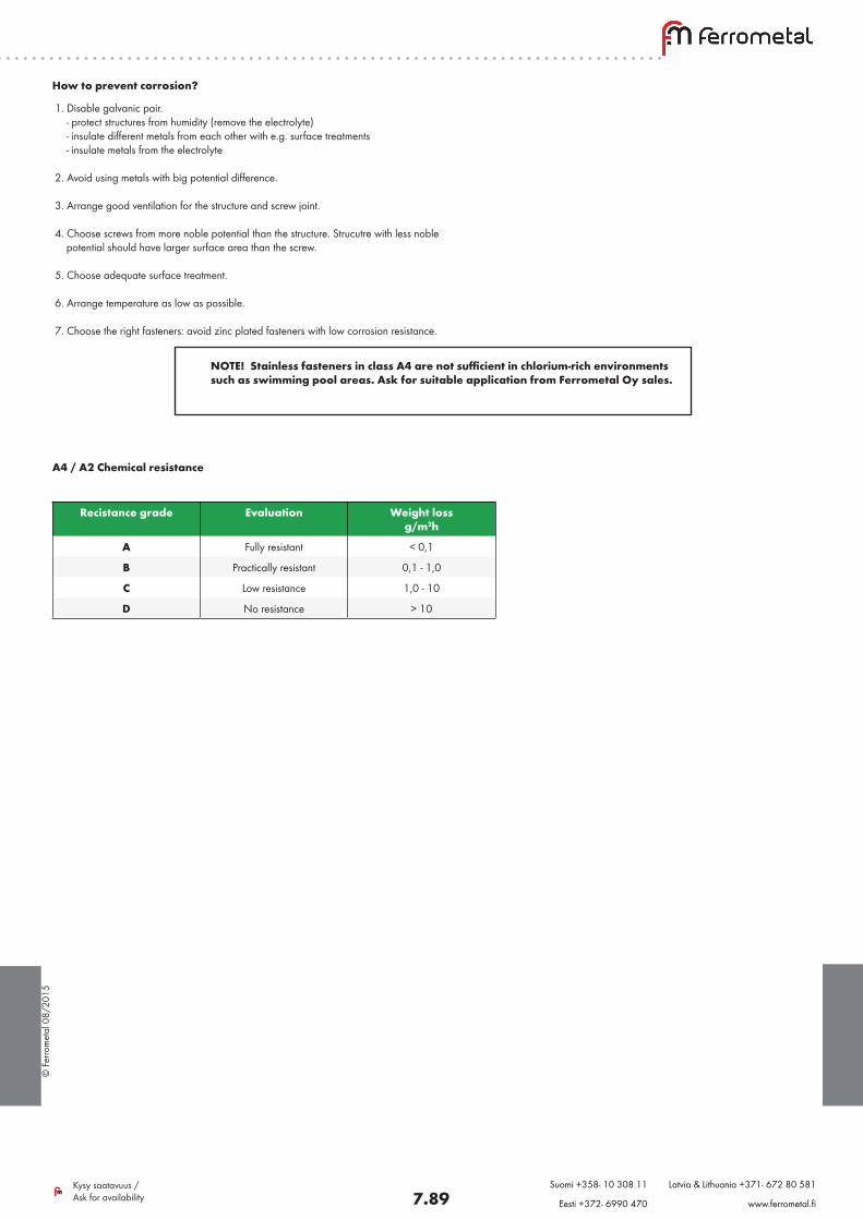
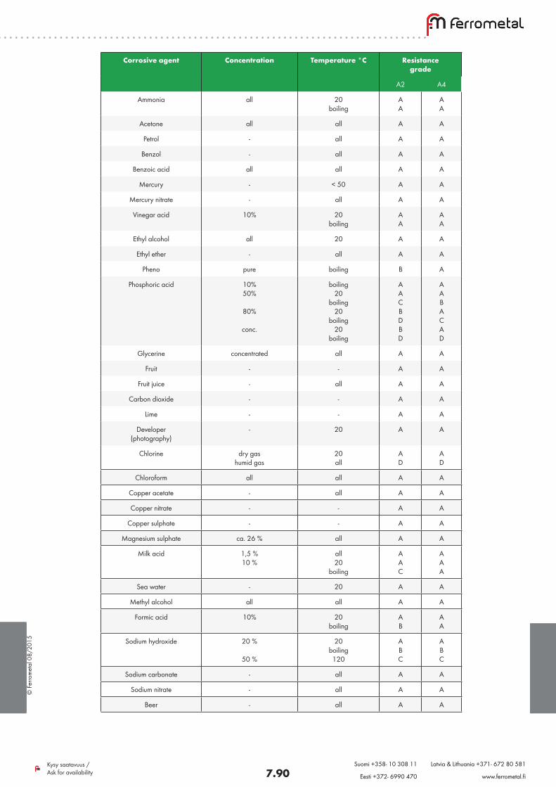
A4 / A2 Chemical resistance
Recistance grade Evaluation Weight lossg/m2h
A Fully resistant < 0,1
B Practically resistant 0,1 - 1,0
C Low resistance 1,0 - 10
D No resistance > 10
How to prevent corrosion?
1. Disable galvanic pair. - protect structures from humidity (remove the electrolyte) - insulate different metals from each other with e.g. surface treatments - insulate metals from the electrolyte
2. Avoid using metals with big potential difference.
3. Arrange good ventilation for the structure and screw joint.
4. Choose screws from more noble potential than the structure. Strucutre with less noble potential should have larger surface area than the screw.
5. Choose adequate surface treatment.
6. Arrange temperature as low as possible.
7. Choose the right fasteners: avoid zinc plated fasteners with low corrosion resistance.
NOTE! Stainless fasteners in class A4 are not sufficient in chlorium-rich environments such as swimming pool areas. Ask for suitable application from Ferrometal Oy sales.
© F
erro
met
al 0
8/20
15
7.90Kysy saatavuus / Ask for availability
Suomi +358- 10 308 11 Latvia & Lithuania +371- 672 80 581
Eesti +372- 6990 470 www.ferrometal.fi
Corrosive agent Concentration Temperature °C Resistancegrade
A2 A4
Ammonia all 20 boiling
AA
AA
Acetone all all A A
Petrol - all A A
Benzol - all A A
Benzoic acid all all A A
Mercury - < 50 A A
Mercury nitrate - all A A
Vinegar acid 10% 20 boiling
AA
AA
Ethyl alcohol all 20 A A
Ethyl ether - all A A
Pheno pure boiling B A
Phosphoric acid 10%50%
80%
conc.
boiling20
boiling20
boiling20
boiling
AACBDBD
AABACAD
Glycerine concentrated all A A
Fruit - - A A
Fruit juice - all A A
Carbon dioxide - - A A
Lime - - A A
Developer(photography)
- 20 A A
Chlorine dry gashumid gas
20 all
AD
AD
Chloroform all all A A
Copper acetate - all A A
Copper nitrate - - A A
Copper sulphate - - A A
Magnesium sulphate ca. 26 % all A A
Milk acid 1,5 %10 %
all20
boiling
AAC
AAA
Sea water - 20 A A
Methyl alcohol all all A A
Formic acid 10% 20boiling
AB
AA
Sodium hydroxide 20 %
50 %
20boiling120
ABC
ABC
Sodium carbonate - all A A
Sodium nitrate - all A A
Beer - all A A
© F
erro
met
al 0
8/20
15
7.91Kysy saatavuus / Ask for availability
Suomi +358- 10 308 11 Latvia & Lithuania +371- 672 80 581
Eesti +372- 6990 470 www.ferrometal.fi
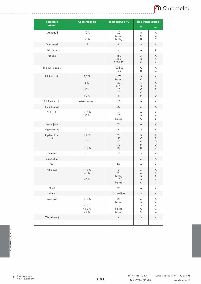
Corrosiveagent
Concentration Temperature °C Resistance grade
A2 A4
Oxalic acid 10 %
50 %
20boilingboiling
BCD
ACC
Tannic acid all all A A
Petroleum - all A A
Fat acid 150180
200-235
ABC
AAA
Sulphuric dioxide - 100-500900
CD
AC
Sulphuric acid 2,5 %
5 %
10%
60 %
< 70boiling
20> 702070all
BCBBCCD
ACABBCD
Sulphurous acid Watery solution 20 A A
Salicylic acid - 20 A A
Citric acid < 10 %50 %
all20
boiling
AAC
AAB
Lemon juice - 20 A A
Sugar solution - all A A
Hydrochloricacid
0,2 %
2 %
< 10 %
2050205020
BCDDD
BBDDD
Cyanide - 20 A A
Industrial air - - A A
Tar - hot A A
Nitric acid < 40 %50 %
90 %
all20
boiling20
boiling
AABAC
AABAC
Blood - 20 A A
Wine - 20 and hot A A
Wine acid < 10 %
> 10 %< 50 %75 %
20boiling
20boilingboiling
A B A C C
A A A C C
Oils (mineral) - all A A
© F
erro
met
al 0
8/20
15
7.92Kysy saatavuus / Ask for availability
Suomi +358- 10 308 11 Latvia & Lithuania +371- 672 80 581
Eesti +372- 6990 470 www.ferrometal.fi
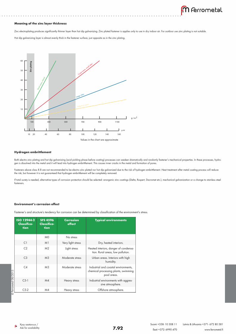
Meaning of the zinc layer thickness
Zinc electroplating produces significantly thinner layer than hot dip galvanizing. Zinc plated fastener is applies only to use in dry indoor air. For outdoor use zinc plating is not suitable.
Hot dip galvanizing layer is almost evenly thick in the fastener surface, just opposite as in the zinc plating.
Hydrogen embrittlement
Both electro zinc plating and hot dip galvanizing (acid pickling phase before coating) processes can weaken dramatically and randomly fastener’s mechanical properties. In these processes, hydro-gen is dissolved into the metal and it will lead into hydrogen embrittlement. This causes inner cracks in the metal and formation of pores.
Fasteners above class 8.8 are not recommended to be electro zinc plated nor hot dip galvanized due to the risk of hydrogen embrittlement. Heat treatment after metal coating process will reduce the risk, but however it is not guaranteed that hydrogen embrittlement will be completely removed.
If total surety is needed, alternative types of corrosion protection should be selected: anorganic zinc coatings (Delta, Ruspert, Dacromet etc.), mechanical galvanization or a change to stainless steel fasteners.
100 300 500 700 900 1100
10
20
30
40
50
60
10 20 40 60 80 100 120 140 160
g / m
µ m
2
Values in the chart are approximate
Zinc
pla
ting
Rura
l are
as, in
land
Coast area
s, small c
ities
Large cities
Industrial areas
Environment’s corrosion effect
Fastener’s and structure’s tendency for corrosion can be determined by classification of the environment’s stress.
ISO 12944-2Classifica-
tion
SFS 4596Classifica-
tion
Corrosioneffect
Typical environments
M0 No stress
C1 M1 Very light stress Dry, heated interiors.
C2 M2 Light stress Heated interiors, danger of condensa-tion. Rural areas, low pollution.
C3 M3 Moderate stress Urban areas. Interiors with high humidity.
C4 M3 Moderate stress Industrial and coastal environments, chemical processing plants, swimming
pool areas.
C5-1 M4 Heavy stress Industrial environments with aggres-sive atmosphere.
C5-2 M4 Heavy stress Offshore atmosphere.
© F
erro
met
al 0
8/20
15
7.93Kysy saatavuus / Ask for availability
Suomi +358- 10 308 11 Latvia & Lithuania +371- 672 80 581
Eesti +372- 6990 470 www.ferrometal.fi
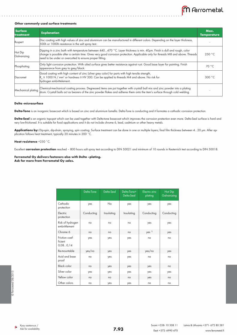
Other commonly used surface treatments
Surface treatment Explanation Max.
Temperature
Ruspert Disc coating with high values of zinc and aluminium can be manufactured in different colors. Depending on the layer thickness, 500h or 1000h resistance in the salt spray test. -
Hot Dip Galvanizing
Dipping in a zinc bath with temperature between 440…470 °C. Layer thickness is min. 40µm. Finish is dull and rough, color change is possible after a certain time. Gives very good corrosion protection. Applicable only for threads M8 and above. Threads need to be under or overcutted to ensure proper fitting.
250 °C
Phosphating Only light corrosion protection. With oiled surface gives better resistance against rust. Good base layer for painting. Finish appearance from grey to grey/black. 70 °C
DacrometGood coating with high content of zinc (silver grey color) for parts with high tensile strength, Rm ≥ 1000 N / mm2 or hardness ≥ HV 300. Can be applied to threads M4 and above. No risk for hydrogen embrittelement.
300 °C
Mechanical plating Chemical-mechanical coating process. Degreased items are put together with crystall ball mix and zinc powder into a plating drum. Crystall balls act as bearers of the zinc powder flakes and adheres them onto the item’s surface through cold welding. -
Delta -microsurface
Delta-Tone is an inorganic basecoat which is based on zinc and aluminium lamella. Delta-Tone is conducting and it formates a cathodic corrosion protection.
Delta-Seal is an organic topcpat which can be used together with Delta-tone basecoat which improves the corrosion protection even more. Delta-Seal surface is hard and very low-frictioned. It is suitable for food applications and it do not include chrome 6, lead, cadmium or other heavy metals.
Applications by: Dip-spin, dip-drain, spraying, spin coating. Surface treatment can be done in one or multiple layers; final film thickness between 4…20 µm. After ap-plication follows heat treatment, typically 20 minutes in 200 ˚C.
Heat resistance +250 ˚C.
Excellent corrosion protection reached – 800 hours salt spray test according to DIN 50021 and minimum of 10 rounds in Kesternich test according to DIN 50018.
Ferrometal Oy delivers fasteners also with Delta –plating. Ask for more from Ferrometal Oy sales.
Delta-Tone Delta-Seal Delta-Tone+Delta-Seal
Electro zincplating
Hot DipGalvanizing
Cathodicprotection
yes No yes yes yes
Electricprotection
Conducting Insulating Insulating Conducting Conducting
Risk of hydrogenembrittlement
no no no yes yes
Chrome 6 no no no yes 1) yes
Friction coef-ficient0,08…0,14
yes yes yes no no
Re-mountable yes/no yes yes yes/no yes
Acid and baseproof
no yes yes no no
Black color no yes yes yes no
Silver color yes yes yes yes yes
Yellow color no no no yes no
Other colors no yes yes no no
© F
erro
met
al 0
8/20
15
7.94Kysy saatavuus / Ask for availability
Suomi +358- 10 308 11 Latvia & Lithuania +371- 672 80 581
Eesti +372- 6990 470 www.ferrometal.fi
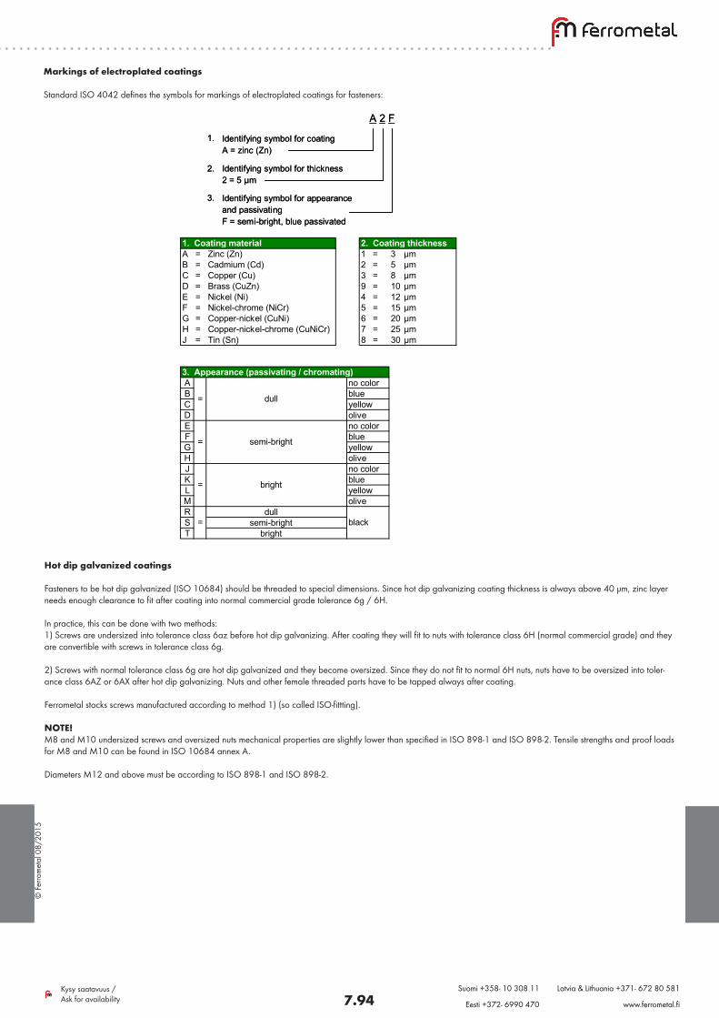
Markings of electroplated coatings
Standard ISO 4042 defines the symbols for markings of electroplated coatings for fasteners:
1. Coating material 2. Coating thicknessA = Zinc (Zn) 1 = 3 µmB = Cadmium (Cd) 2 = 5 µmC = Copper (Cu) 3 = 8 µmD = Brass (CuZn) 9 = 10 µmE = Nickel (Ni) 4 = 12 µmF = Nickel-chrome (NiCr) 5 = 15 µmG = Copper-nickel (CuNi) 6 = 20 µmH = Copper-nickel-chrome (CuNiCr) 7 = 25 µmJ = Tin (Sn) 8 = 30 µm
3. Appearance (passivating / chromating)ABCDEFGHJKLMR dullS semi-brightT bright
= dull
semi-bright
bright
=
=
no colorblueyellowolive
=
no colorblueyellowoliveno colorblueyellow
black
olive
A 2 F
Identifying symbol for coatingA = zinc (Zn)
Identifying symbol for thickness2 = 5 µm
Identifying symbol for appearanceand passivatingF = semi-bright, blue passivated
1.
2.
3.
A 2 F
Identifying symbol for coatingA = zinc (Zn)
Identifying symbol for thickness2 = 5 µm
Identifying symbol for appearanceand passivatingF = semi-bright, blue passivated
1.
2.
3.
Hot dip galvanized coatings
Fasteners to be hot dip galvanized (ISO 10684) should be threaded to special dimensions. Since hot dip galvanizing coating thickness is always above 40 µm, zinc layer needs enough clearance to fit after coating into normal commercial grade tolerance 6g / 6H.
In practice, this can be done with two methods:1) Screws are undersized into tolerance class 6az before hot dip galvanizing. After coating they will fit to nuts with tolerance class 6H (normal commercial grade) and they are convertible with screws in tolerance class 6g.
2) Screws with normal tolerance class 6g are hot dip galvanized and they become oversized. Since they do not fit to normal 6H nuts, nuts have to be oversized into toler-ance class 6AZ or 6AX after hot dip galvanizing. Nuts and other female threaded parts have to be tapped always after coating.
Ferrometal stocks screws manufactured according to method 1) (so called ISO-fittting). NOTE!M8 and M10 undersized screws and oversized nuts mechanical properties are slightly lower than specified in ISO 898-1 and ISO 898-2. Tensile strengths and proof loads for M8 and M10 can be found in ISO 10684 annex A.
Diameters M12 and above must be according to ISO 898-1 and ISO 898-2.
© F
erro
met
al 0
8/20
15
7.95Kysy saatavuus / Ask for availability
Suomi +358- 10 308 11 Latvia & Lithuania +371- 672 80 581
Eesti +372- 6990 470 www.ferrometal.fi
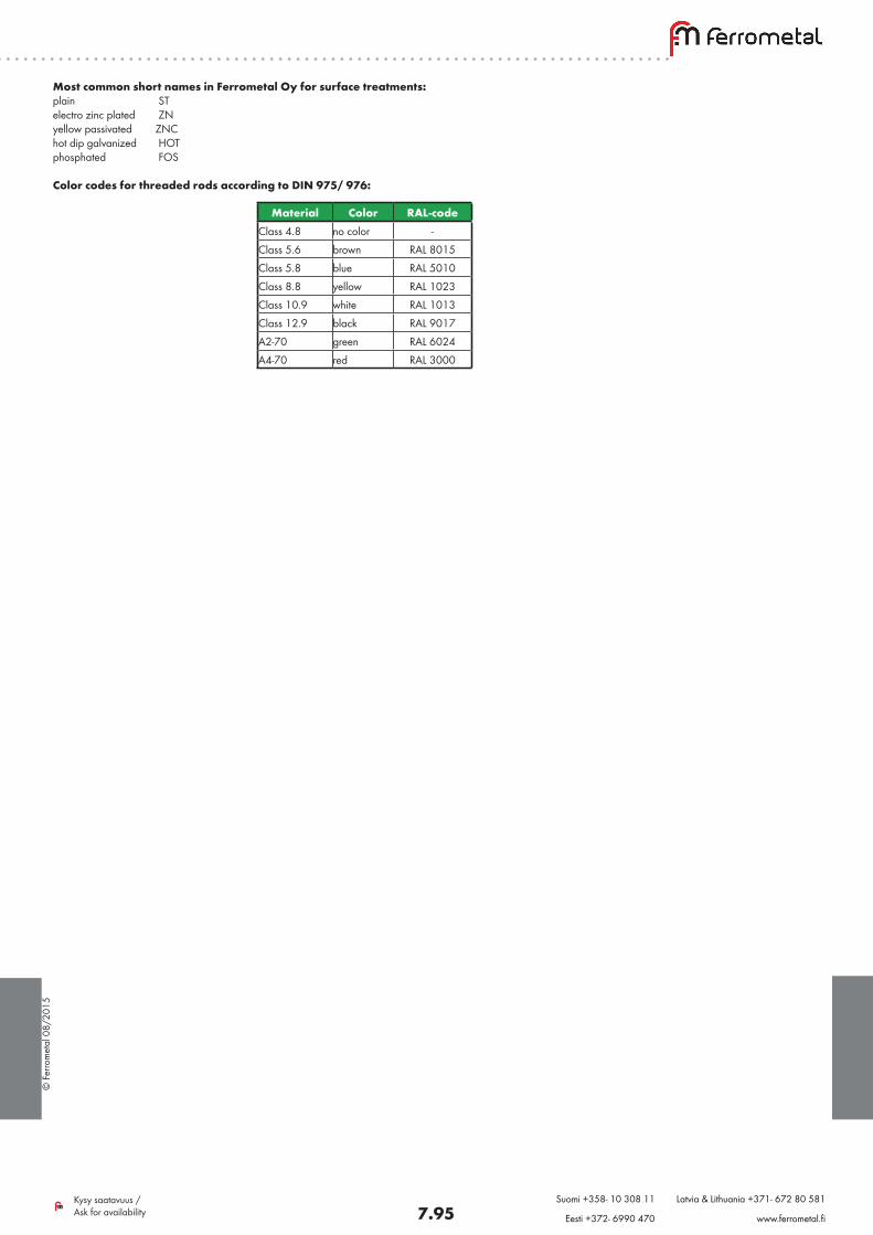
Most common short names in Ferrometal Oy for surface treatments:plain STelectro zinc plated ZNyellow passivated ZNChot dip galvanized HOTphosphated FOS
Color codes for threaded rods according to DIN 975/ 976:
Material Color RAL-codeClass 4.8 no color -Class 5.6 brown RAL 8015Class 5.8 blue RAL 5010Class 8.8 yellow RAL 1023Class 10.9 white RAL 1013Class 12.9 black RAL 9017A2-70 green RAL 6024A4-70 red RAL 3000
© F
erro
met
al 0
8/20
15
7.96Kysy saatavuus / Ask for availability
Suomi +358- 10 308 11 Latvia & Lithuania +371- 672 80 581
Eesti +372- 6990 470 www.ferrometal.fi
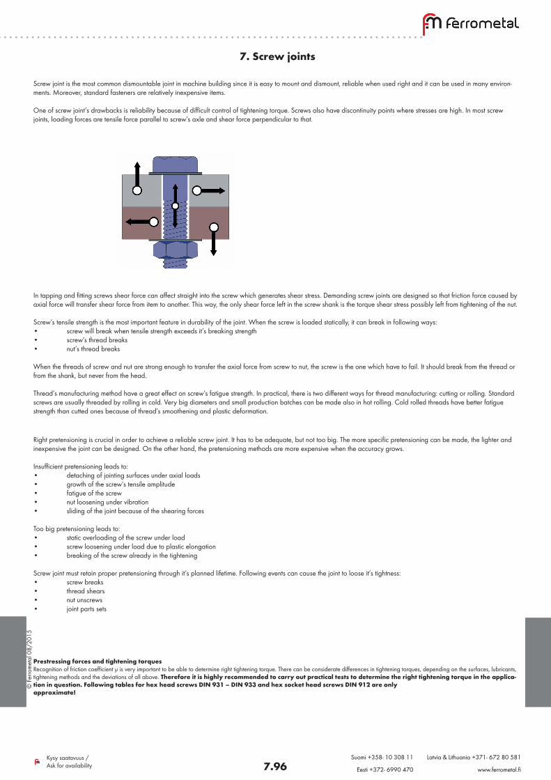
7. Screw joints
Screw joint is the most common dismountable joint in machine building since it is easy to mount and dismount, reliable when used right and it can be used in many environ-ments. Moreover, standard fasteners are relatively inexpensive items.
One of screw joint’s drawbacks is reliability because of difficult control of tightening torque. Screws also have discontinuity points where stresses are high. In most screw joints, loading forces are tensile force parallel to screw’s axle and shear force perpendicular to that.
In tapping and fitting screws shear force can affect straight into the screw which generates shear stress. Demanding screw joints are designed so that friction force caused by axial force will transfer shear force from item to another. This way, the only shear force left in the screw shank is the torque shear stress possibly left from tightening of the nut.
Screw’s tensile strength is the most important feature in durability of the joint. When the screw is loaded statically, it can break in following ways:• screw will break when tensile strength exceeds it’s breaking strength• screw’s thread breaks• nut’s thread breaks
When the threads of screw and nut are strong enough to transfer the axial force from screw to nut, the screw is the one which have to fail. It should break from the thread or from the shank, but never from the head.
Thread’s manufacturing method have a great effect on screw’s fatigue strength. In practical, there is two different ways for thread manufacturing: cutting or rolling. Standard screws are usually threaded by rolling in cold. Very big diameters and small production batches can be made also in hot rolling. Cold rolled threads have better fatigue strength than cutted ones because of thread’s smoothening and plastic deformation.
Right pretensioning is crucial in order to achieve a reliable screw joint. It has to be adequate, but not too big. The more specific pretensioning can be made, the lighter and inexpensive the joint can be designed. On the other hand, the pretensioning methods are more expensive when the accuracy grows.
Insufficient pretensioning leads to:• detaching of jointing surfaces under axial loads• growth of the screw’s tensile amplitude• fatigue of the screw• nut loosening under vibration• sliding of the joint because of the shearing forces
Too big pretensioning leads to:• static overloading of the screw under load• screw loosening under load due to plastic elongation• breaking of the screw already in the tightening
Screw joint must retain proper pretensioning through it’s planned lifetime. Following events can cause the joint to loose it’s tightness:• screw breaks• thread shears• nut unscrews• joint parts sets
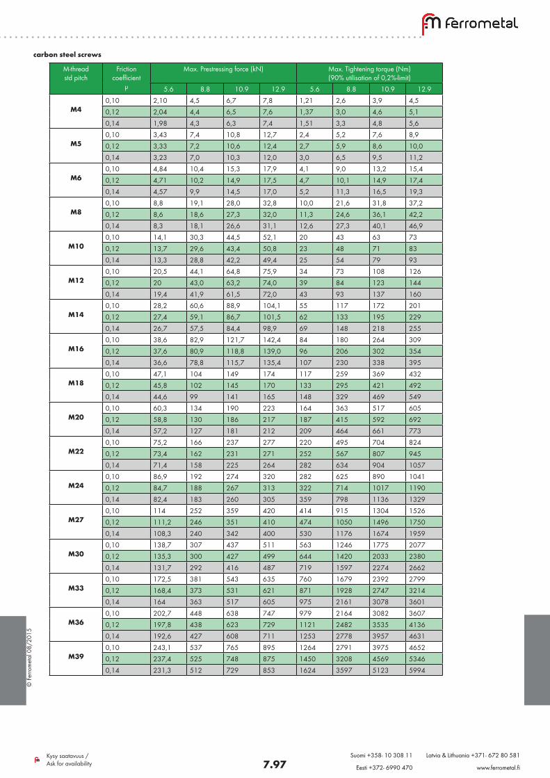
Prestressing forces and tightening torquesRecognition of friction coefficient µ is very important to be able to determine right tightening torque. There can be considerate differences in tightening torques, depending on the surfaces, lubricants, tightening methods and the deviations of all above. Therefore it is highly recommended to carry out practical tests to determine the right tightening torque in the applica-tion in question. Following tables for hex head screws DIN 931 – DIN 933 and hex socket head screws DIN 912 are only approximate!
© F
erro
met
al 0
8/20
15
7.97Kysy saatavuus / Ask for availability
Suomi +358- 10 308 11 Latvia & Lithuania +371- 672 80 581
Eesti +372- 6990 470 www.ferrometal.fi
carbon steel screws
M-thread std pitch
Friction coefficient
µ
Max. Prestressing force (kN) Max. Tightening torque (Nm) (90% utilisation of 0,2%-limit)
5.6 8.8 10.9 12.9 5.6 8.8 10.9 12.9
M40,10 2,10 4,5 6,7 7,8 1,21 2,6 3,9 4,50,12 2,04 4,4 6,5 7,6 1,37 3,0 4,6 5,10,14 1,98 4,3 6,3 7,4 1,51 3,3 4,8 5,6
M5
0,10 3,43 7,4 10,8 12,7 2,4 5,2 7,6 8,90,12 3,33 7,2 10,6 12,4 2,7 5,9 8,6 10,00,14 3,23 7,0 10,3 12,0 3,0 6,5 9,5 11,2
M6
0,10 4,84 10,4 15,3 17,9 4,1 9,0 13,2 15,40,12 4,71 10,2 14,9 17,5 4,7 10,1 14,9 17,40,14 4,57 9,9 14,5 17,0 5,2 11,3 16,5 19,3
M8
0,10 8,8 19,1 28,0 32,8 10,0 21,6 31,8 37,20,12 8,6 18,6 27,3 32,0 11,3 24,6 36,1 42,20,14 8,3 18,1 26,6 31,1 12,6 27,3 40,1 46,9
M10
0,10 14,1 30,3 44,5 52,1 20 43 63 730,12 13,7 29,6 43,4 50,8 23 48 71 830,14 13,3 28,8 42,2 49,4 25 54 79 93
M12
0,10 20,5 44,1 64,8 75,9 34 73 108 1260,12 20 43,0 63,2 74,0 39 84 123 1440,14 19,4 41,9 61,5 72,0 43 93 137 160
M14
0,10 28,2 60,6 88,9 104,1 55 117 172 2010,12 27,4 59,1 86,7 101,5 62 133 195 2290,14 26,7 57,5 84,4 98,9 69 148 218 255
M160,10 38,6 82,9 121,7 142,4 84 180 264 3090,12 37,6 80,9 118,8 139,0 96 206 302 3540,14 36,6 78,8 115,7 135,4 107 230 338 395
M180,10 47,1 104 149 174 117 259 369 4320,12 45,8 102 145 170 133 295 421 4920,14 44,6 99 141 165 148 329 469 549
M20
0,10 60,3 134 190 223 164 363 517 6050,12 58,8 130 186 217 187 415 592 6920,14 57,2 127 181 212 209 464 661 773
M22
0,10 75,2 166 237 277 220 495 704 8240,12 73,4 162 231 271 252 567 807 9450,14 71,4 158 225 264 282 634 904 1057
M24
0,10 86,9 192 274 320 282 625 890 10410,12 84,7 188 267 313 322 714 1017 11900,14 82,4 183 260 305 359 798 1136 1329
M27
0,10 114 252 359 420 414 915 1304 15260,12 111,2 246 351 410 474 1050 1496 17500,14 108,3 240 342 400 530 1176 1674 1959
M30
0,10 138,7 307 437 511 563 1246 1775 20770,12 135,3 300 427 499 644 1420 2033 23800,14 131,7 292 416 487 719 1597 2274 2662
M33
0,10 172,5 381 543 635 760 1679 2392 27990,12 168,4 373 531 621 871 1928 2747 32140,14 164 363 517 605 975 2161 3078 3601
M36
0,10 202,7 448 638 747 979 2164 3082 36070,12 197,8 438 623 729 1121 2482 3535 41360,14 192,6 427 608 711 1253 2778 3957 4631
M39
0,10 243,1 537 765 895 1264 2791 3975 46520,12 237,4 525 748 875 1450 3208 4569 53460,14 231,3 512 729 853 1624 3597 5123 5994
© F
erro
met
al 0
8/20
15
7.98Kysy saatavuus / Ask for availability
Suomi +358- 10 308 11 Latvia & Lithuania +371- 672 80 581
Eesti +372- 6990 470 www.ferrometal.fi
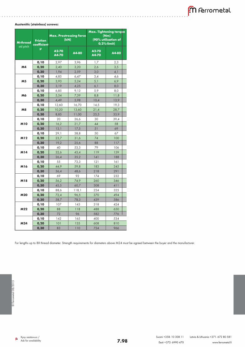
Austenitic (stainless) screws:
For lengths up to 8X thread diameter. Strength requirements for diameters above M24 must be agreed between the buyer and the manufacturer.
M-thread std pitch
Friction coefficient
µ
Max. Prestressing force (kN)
Max. Tightening torque (Nm)
(90% utilisation of 0,2%-limit)
A2-70 A4-70 A4-80 A2-70
A4-70 A4-80
M40,10 2,97 3,96 1,7 2,30,20 2,40 3,20 2,6 3,50,30 1,94 2,59 3,0 4,1
M50,10 4,85 6,47 3,4 4,60,20 3,93 5,24 5,1 6,90,30 3,19 4,25 6,1 8,0
M60,10 6,85 9,13 5,9 8,00,20 5,54 7,39 8,8 11,80,30 4,49 5,98 10,4 13,9
M80,10 12,60 16,70 14,5 19,30,20 10,20 13,60 21,4 28,70,30 8,85 11,00 25,5 33,9
M100,10 20 26,6 30 39,40,20 16,2 21,7 44 580,30 13,1 17,5 51 69
M120,10 29,1 38,8 50 670,20 23,7 31,6 74 1000,30 19,2 25,6 88 117
M140,10 40 53,3 79 1060,20 32,6 43,4 119 1590,30 26,4 35,2 141 188
M160,10 55 73,3 121 1610,20 44,9 59,8 183 2450,30 36,4 48,6 218 291
M180,10 69 92 174 2320,20 56,2 74,9 260 3460,30 45,5 60,7 308 411
M200,10 88,6 118,1 224 3250,20 72,4 96,5 370 4940,30 58,7 78,3 439 586
M220,10 107 143 318 4240,20 88 118 488 6500,30 72 96 582 776
M240,10 142 165 400 5340,20 101 135 608 8100,30 83 110 724 966
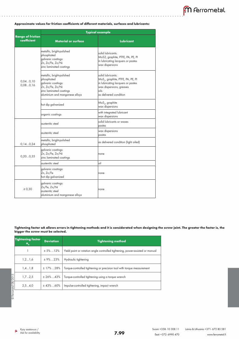
© F
erro
met
al 0
8/20
15
7.99Kysy saatavuus / Ask for availability
Suomi +358- 10 308 11 Latvia & Lithuania +371- 672 80 581
Eesti +372- 6990 470 www.ferrometal.fi
Approximate values for friction coefficients of different materials, surfaces and lubricants:
Range of friction coefficient
Typical example
Material or surface Lubricant
0,04…0,100,08…0,16
metallic, bright-polished phosphated galvanic coatings: Zn, Zn/Fe, Zn/Ni zinc laminated coatings
solid lubricants: MoS2, graphite, PTFE, PA, PE, PI in lubricating lacquers or pastes wax dispersions
metallic, bright-polished phosphated galvanic coatings: Zn, Zn/Fe, Zn/Ni zinc laminated coatings aluminium and manganese alloys
solid lubricants: MoS2, graphite, PTFE, PA, PE, PI in lubricating lacquers or pastes wax dispersions, greases oils as delivered condition
hot dip galvanized MoS2, graphite wax dispersions
organic coatings with integrated lubricant wax dispersions
0,14…0,24
austenitic steel solid lubricants or waxes pastes
austenitic steel wax dispersions pastes
metallic, bright-polished phosphated as delivered condition (light oiled)
0,20…0,35
galvanic coatings: Zn, Zn/Fe, Zn/Ni zinc laminated coatings
none
austenitic steel oil
galvanic coatings: Zn, Zn/Fe hot dip galvanized
none
≥ 0,30
galvanic coatings: Zn/Fe, Zn/Ni austenitic steel aluminium and manganese alloys
none
Tightening factor αA allows errors in tightening methods and it is considerated when designing the screw joint. The greater the factor is, the bigger the screw must be selected.
Tightening factor αA
Deviation Tightening method
1 ± 5% …12% Yield point or rotation angle controlled tightening, power-assisted or manual
1,2…1,6 ± 9% …23% Hydraulic tightening
1,4…1,8 ± 17% …28% Torque-controlled tightening or precision tool with torque measurement
1,7…2,5 ± 26% …43% Torque-controlled tightening using a torque wrench
2,5…4,0 ± 43% …60% Impulse-controlled tightening, impact wrench
© F
erro
met
al 0
8/20
15
7.100Kysy saatavuus / Ask for availability
Suomi +358- 10 308 11 Latvia & Lithuania +371- 672 80 581
Eesti +372- 6990 470 www.ferrometal.fi
Friction grip (HV) fasteners Changeover to EN –product standards in structural fasteners
Changeover
DIN 6914 EN 14399-4
DIN 6915 EN 14399-4
DIN 6916 EN 14399-6
Washers according to DIN 6917 and DIN 6918 remain as they are defined in DIN –standards. In joints where DIN –standardized products are specified EN products can be used since they are technically equivalent or better. This is not the case vice versa.
Ordering information
DIN
Hexagon screw DIN 6914 10.9 HOT M20X80Hexagon nut DIN 6915 10 HOT M20Washer DIN 6916 HOT M20 (21.0)
EN
Hexagon screw / nut assembly EN 14399-4 HV 10.9/10 HOT M16X70Washer EN 14399-6 HOT M20 (21.0)
Deadlines for product standards
Untill September 2007, German national standards DIN 6914, DIN 6915 and DIN 6916 existed side by side with European standards EN 14399-4 and -6. After that only products according to EN with CE –marking are allowed to be produced. HV –sets on stock according to DIN 6914 / 6915 / 6916 are allowed to be supplied and used without any limitation in time.
Properties
HV (Hoch Vorgespannt) is the term used for steel construction joints with high tensile screws. Special requirements are set to these screws, washers and nuts since they have to establish a safe and tested joint. They can be used only for constructions with mainly static load, such as halls, platforms and framework constructions.
The surface treatment in HV –fasteners are usually hot dip galvanizing. Zinc layer thickness is even up to 50…70 µm. This gives sufficient corrosion protection also in the most aggressive atmospheres. Together with known surface properties and defined friction coefficient of nuts treated by MoS2, proper tightening values can be determined. HV –fasteners are also available in plain finish.
Screw and nut set EN 14399-4 and washer EN 14399-6 form a complete set which should be delivered from the same manufacturer. Ferrometal Oy stocks a wide range of HV-sets produced by our high quality partner Peiner Umformtechnik GmbH.
Example:From above tables, search maximum tightening torque and the corresponding maximum prestressing force for hex head screw DIN 931 8.8 ZN M16X80. Joint is assem-bled with torque measuring precision tool and without lubricants.
1) The screw is electro zinc plated and no lubricant is used. Friction coefficient is 0,14…0,24. Lower value 0,14 is chosen.
2) From the carbon steel screw table, search M16 / 0,14 / 8.8 Maximum tightening torque is 230 Nm.
3) From the same table, search maximum prestressing force. 230 Nm results max. prestressing force 78,8 kN.
4) Prestressing force is corrected with the tightening factor αA. Minimum expected prestressing force is 78,8 kN / 1,6 = 49,25 kN.
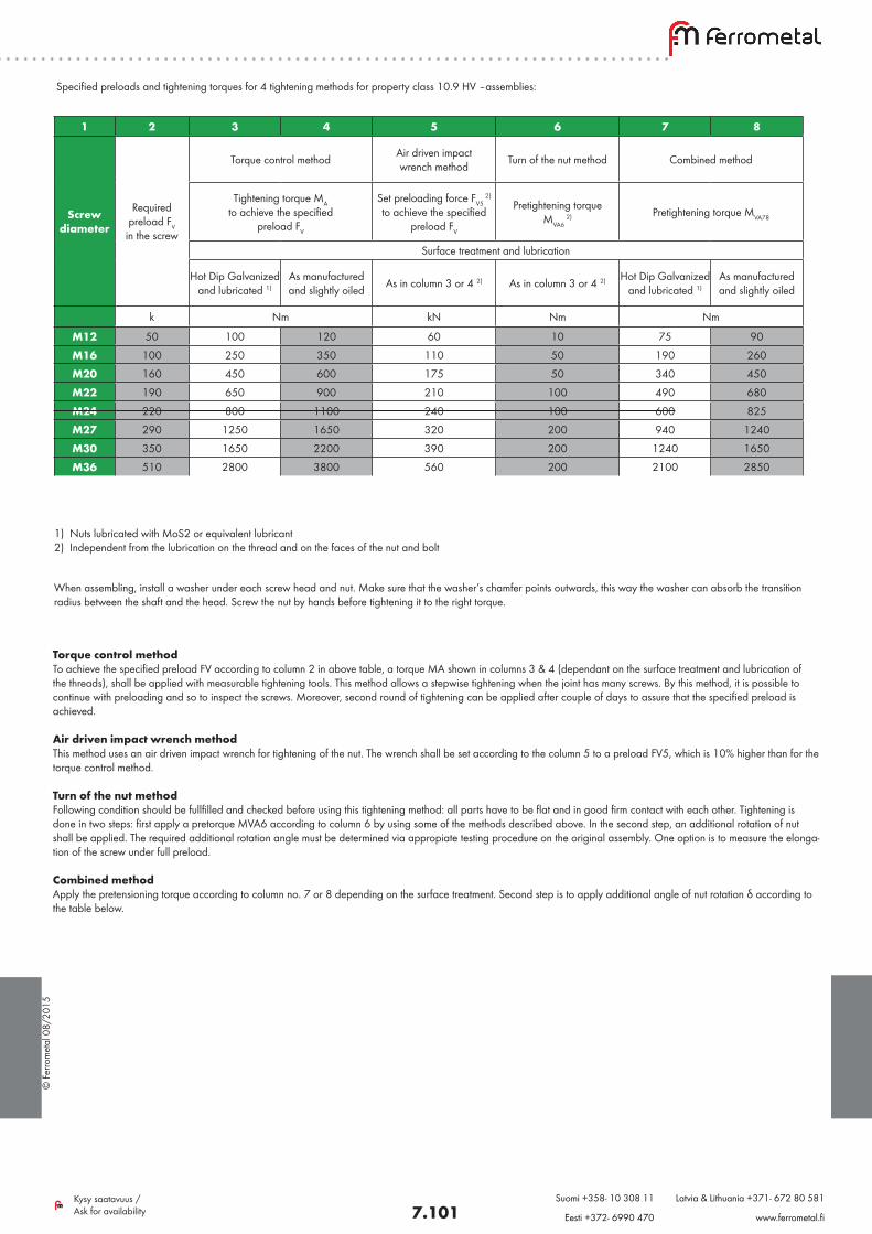
© F
erro
met
al 0
8/20
15
7.101Kysy saatavuus / Ask for availability
Suomi +358- 10 308 11 Latvia & Lithuania +371- 672 80 581
Eesti +372- 6990 470 www.ferrometal.fi
Torque control methodTo achieve the specified preload FV according to column 2 in above table, a torque MA shown in columns 3 & 4 (dependant on the surface treatment and lubrication of the threads), shall be applied with measurable tightening tools. This method allows a stepwise tightening when the joint has many screws. By this method, it is possible to continue with preloading and so to inspect the screws. Moreover, second round of tightening can be applied after couple of days to assure that the specified preload is achieved.
Air driven impact wrench methodThis method uses an air driven impact wrench for tightening of the nut. The wrench shall be set according to the column 5 to a preload FV5, which is 10% higher than for the torque control method.
Turn of the nut methodFollowing condition should be fullfilled and checked before using this tightening method: all parts have to be flat and in good firm contact with each other. Tightening is done in two steps: first apply a pretorque MVA6 according to column 6 by using some of the methods described above. In the second step, an additional rotation of nut shall be applied. The required additional rotation angle must be determined via appropiate testing procedure on the original assembly. One option is to measure the elonga-tion of the screw under full preload.
Combined methodApply the pretensioning torque according to column no. 7 or 8 depending on the surface treatment. Second step is to apply additional angle of nut rotation δ according to the table below.
1 2 3 4 5 6 7 8
Screw diameter
Required preload FV
in the screw
Torque control method Air driven impact wrench method Turn of the nut method Combined method
Tightening torque MA to achieve the specified
preload FV
Set preloading force FV5 2)
to achieve the specified preload FV
Pretightening torque MVA6
2) Pretightening torque MVA78
Surface treatment and lubrication
Hot Dip Galvanized and lubricated 1)
As manufactured and slightly oiled As in column 3 or 4 2) As in column 3 or 4 2) Hot Dip Galvanized
and lubricated 1)As manufactured and slightly oiled
k Nm kN Nm Nm
M12 50 100 120 60 10 75 90
M16 100 250 350 110 50 190 260
M20 160 450 600 175 50 340 450
M22 190 650 900 210 100 490 680
M24 220 800 1100 240 100 600 825
M27 290 1250 1650 320 200 940 1240
M30 350 1650 2200 390 200 1240 1650
M36 510 2800 3800 560 200 2100 2850
1) Nuts lubricated with MoS2 or equivalent lubricant2) Independent from the lubrication on the thread and on the faces of the nut and bolt
When assembling, install a washer under each screw head and nut. Make sure that the washer’s chamfer points outwards, this way the washer can absorb the transition radius between the shaft and the head. Screw the nut by hands before tightening it to the right torque.
Specified preloads and tightening torques for 4 tightening methods for property class 10.9 HV –assemblies:
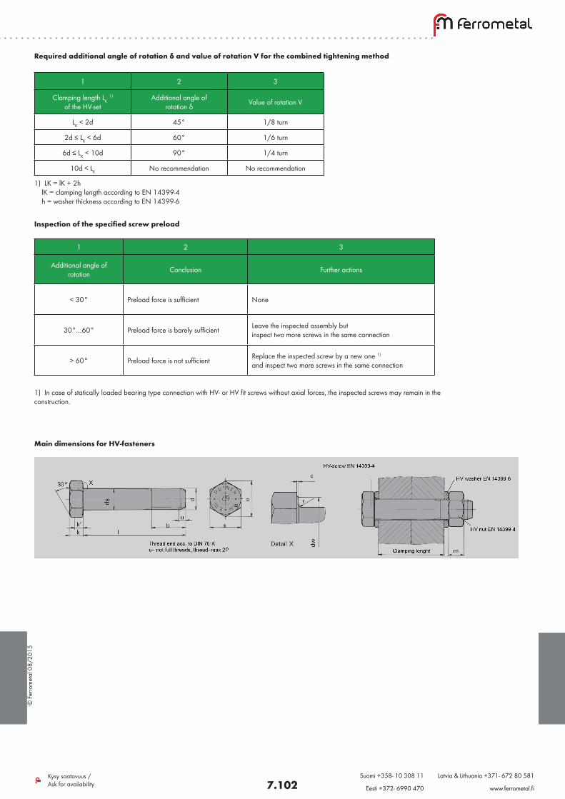
© F
erro
met
al 0
8/20
15
7.102Kysy saatavuus / Ask for availability
Suomi +358- 10 308 11 Latvia & Lithuania +371- 672 80 581
Eesti +372- 6990 470 www.ferrometal.fi
Inspection of the specified screw preload
1) In case of statically loaded bearing type connection with HV- or HV fit screws without axial forces, the inspected screws may remain in the construction.
1 2 3
Additional angle of rotation Conclusion Further actions
< 30° Preload force is sufficient None
30°…60° Preload force is barely sufficient Leave the inspected assembly but inspect two more screws in the same connection
> 60° Preload force is not sufficient Replace the inspected screw by a new one 1) and inspect two more screws in the same connection
1 2 3
Clamping length LK 1)
of the HV-setAdditional angle of
rotation δ Value of rotation V
LK < 2d 45° 1/8 turn
2d ≤ LK < 6d 60° 1/6 turn
6d ≤ LK < 10d 90° 1/4 turn
10d < LK No recommendation No recommendation
1) LK = lK + 2h lK = clamping length according to EN 14399-4 h = washer thickness according to EN 14399-6
Required additional angle of rotation δ and value of rotation V for the combined tightening method
Main dimensions for HV-fasteners
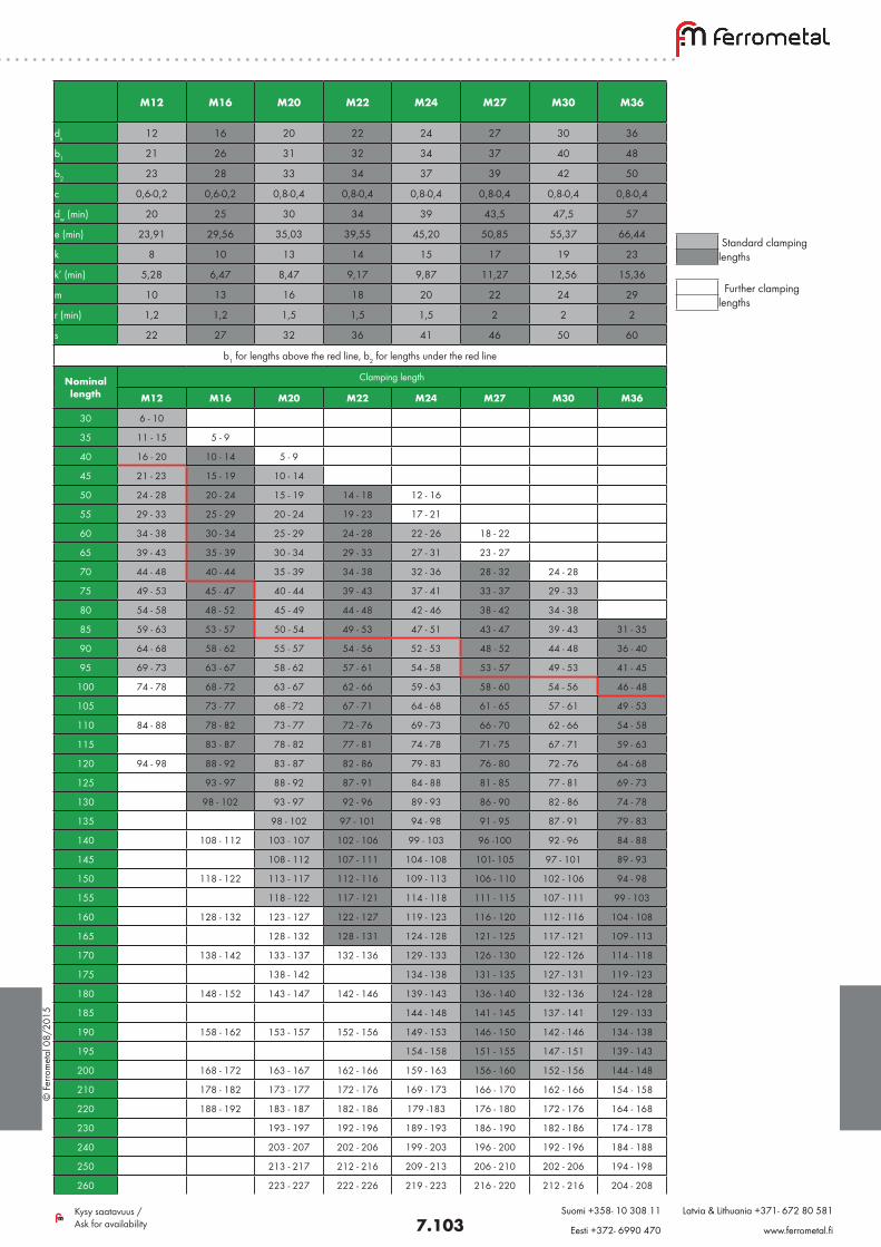
© F
erro
met
al 0
8/20
15
7.103Kysy saatavuus / Ask for availability
Suomi +358- 10 308 11 Latvia & Lithuania +371- 672 80 581
Eesti +372- 6990 470 www.ferrometal.fi
M12 M16 M20 M22 M24 M27 M30 M36
ds 12 16 20 22 24 27 30 36
b1 21 26 31 32 34 37 40 48
b2 23 28 33 34 37 39 42 50
c 0,6-0,2 0,6-0,2 0,8-0,4 0,8-0,4 0,8-0,4 0,8-0,4 0,8-0,4 0,8-0,4
dw (min) 20 25 30 34 39 43,5 47,5 57
e (min) 23,91 29,56 35,03 39,55 45,20 50,85 55,37 66,44
k 8 10 13 14 15 17 19 23
k’ (min) 5,28 6,47 8,47 9,17 9,87 11,27 12,56 15,36
m 10 13 16 18 20 22 24 29
r (min) 1,2 1,2 1,5 1,5 1,5 2 2 2
s 22 27 32 36 41 46 50 60
b1 for lengths above the red line, b2 for lengths under the red line
Nominal length
Clamping length
M12 M16 M20 M22 M24 M27 M30 M36
30 6 - 10
35 11 - 15 5 - 9
40 16 - 20 10 - 14 5 - 9
45 21 - 23 15 - 19 10 - 14
50 24 - 28 20 - 24 15 - 19 14 - 18 12 - 16
55 29 - 33 25 - 29 20 - 24 19 - 23 17 - 21
60 34 - 38 30 - 34 25 - 29 24 - 28 22 - 26 18 - 22
65 39 - 43 35 - 39 30 - 34 29 - 33 27 - 31 23 - 27
70 44 - 48 40 - 44 35 - 39 34 - 38 32 - 36 28 - 32 24 - 28
75 49 - 53 45 - 47 40 - 44 39 - 43 37 - 41 33 - 37 29 - 33
80 54 - 58 48 - 52 45 - 49 44 - 48 42 - 46 38 - 42 34 - 38
85 59 - 63 53 - 57 50 - 54 49 - 53 47 - 51 43 - 47 39 - 43 31 - 35
90 64 - 68 58 - 62 55 - 57 54 - 56 52 - 53 48 - 52 44 - 48 36 - 40
95 69 - 73 63 - 67 58 - 62 57 - 61 54 - 58 53 - 57 49 - 53 41 - 45
100 74 - 78 68 - 72 63 - 67 62 - 66 59 - 63 58 - 60 54 - 56 46 - 48
105 73 - 77 68 - 72 67 - 71 64 - 68 61 - 65 57 - 61 49 - 53
110 84 - 88 78 - 82 73 - 77 72 - 76 69 - 73 66 - 70 62 - 66 54 - 58
115 83 - 87 78 - 82 77 - 81 74 - 78 71 - 75 67 - 71 59 - 63
120 94 - 98 88 - 92 83 - 87 82 - 86 79 - 83 76 - 80 72 - 76 64 - 68
125 93 - 97 88 - 92 87 - 91 84 - 88 81 - 85 77 - 81 69 - 73
130 98 - 102 93 - 97 92 - 96 89 - 93 86 - 90 82 - 86 74 - 78
135 98 - 102 97 - 101 94 - 98 91 - 95 87 - 91 79 - 83
140 108 - 112 103 - 107 102 - 106 99 - 103 96 -100 92 - 96 84 - 88
145 108 - 112 107 - 111 104 - 108 101- 105 97 - 101 89 - 93
150 118 - 122 113 - 117 112 - 116 109 - 113 106 - 110 102 - 106 94 - 98
155 118 - 122 117 - 121 114 - 118 111 - 115 107 - 111 99 - 103
160 128 - 132 123 - 127 122 - 127 119 - 123 116 - 120 112 - 116 104 - 108
165 128 - 132 128 - 131 124 - 128 121 - 125 117 - 121 109 - 113
170 138 - 142 133 - 137 132 - 136 129 - 133 126 - 130 122 - 126 114 - 118
175 138 - 142 134 - 138 131 - 135 127 - 131 119 - 123
180 148 - 152 143 - 147 142 - 146 139 - 143 136 - 140 132 - 136 124 - 128
185 144 - 148 141 - 145 137 - 141 129 - 133
190 158 - 162 153 - 157 152 - 156 149 - 153 146 - 150 142 - 146 134 - 138
195 154 - 158 151 - 155 147 - 151 139 - 143
200 168 - 172 163 - 167 162 - 166 159 - 163 156 - 160 152 - 156 144 - 148
210 178 - 182 173 - 177 172 - 176 169 - 173 166 - 170 162 - 166 154 - 158
220 188 - 192 183 - 187 182 - 186 179 -183 176 - 180 172 - 176 164 - 168
230 193 - 197 192 - 196 189 - 193 186 - 190 182 - 186 174 - 178
240 203 - 207 202 - 206 199 - 203 196 - 200 192 - 196 184 - 188
250 213 - 217 212 - 216 209 - 213 206 - 210 202 - 206 194 - 198
260 223 - 227 222 - 226 219 - 223 216 - 220 212 - 216 204 - 208
Standard clamping lengths
Further clamping lengths
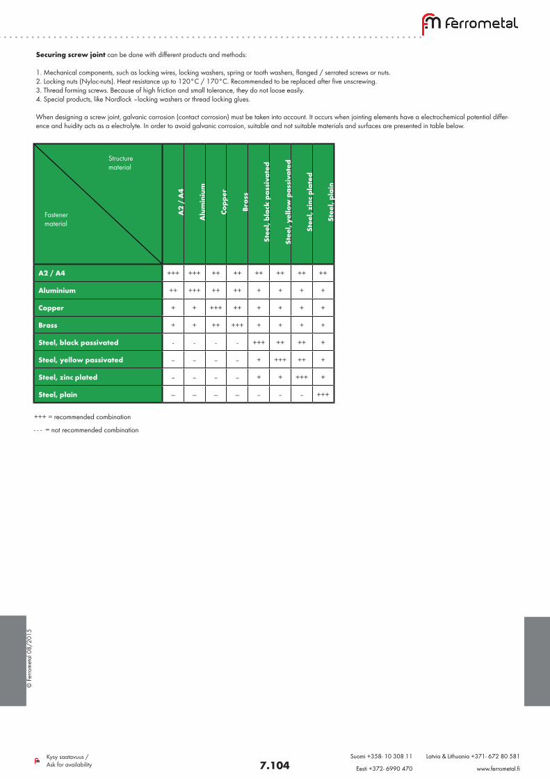
© F
erro
met
al 0
8/20
15
7.104Kysy saatavuus / Ask for availability
Suomi +358- 10 308 11 Latvia & Lithuania +371- 672 80 581
Eesti +372- 6990 470 www.ferrometal.fi
Securing screw joint can be done with different products and methods:
1. Mechanical components, such as locking wires, locking washers, spring or tooth washers, flanged / serrated screws or nuts.2. Locking nuts (Nyloc-nuts). Heat resistance up to 120°C / 170°C. Recommended to be replaced after five unscrewing.3. Thread forming screws. Because of high friction and small tolerance, they do not loose easily.4. Special products, like Nordlock –locking washers or thread locking glues.
When designing a screw joint, galvanic corrosion (contact corrosion) must be taken into account. It occurs when jointing elements have a electrochemical potential differ-ence and huidity acts as a electrolyte. In order to avoid galvanic corrosion, suitable and not suitable materials and surfaces are presented in table below.
A2
/ A
4
Alu
min
ium
Cop
per
Bra
ss
Ste
el, b
lack
pas
siva
ted
Ste
el, y
ello
w p
assi
vate
d
Ste
el, z
inc
plat
ed
Ste
el, p
lain
A2 / A4 +++ +++ ++ ++ ++ ++ ++ ++
Aluminium ++ +++ ++ ++ + + + +
Copper + + +++ ++ + + + +
Brass + + ++ +++ + + + +
Steel, black passivated - - - - +++ ++ ++ +
Steel, yellow passivated -- -- -- -- + +++ ++ +
Steel, zinc plated -- -- -- -- + + +++ +
Steel, plain --- --- --- --- -- -- -- +++
+++ = recommended combination
- - - = not recommended combination
Structure material
Fastener material
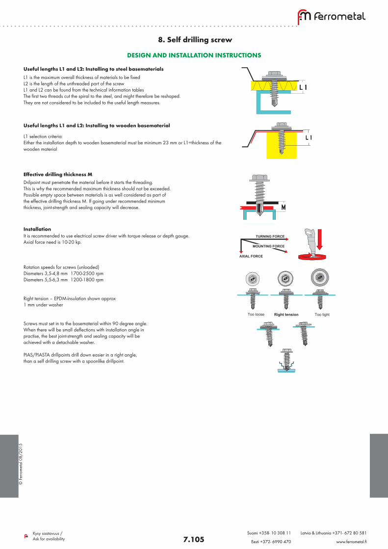
© F
erro
met
al 0
8/20
15
7.105Kysy saatavuus / Ask for availability
Suomi +358- 10 308 11 Latvia & Lithuania +371- 672 80 581
Eesti +372- 6990 470 www.ferrometal.fi
8. Self drilling screw
L1 is the maximum overall thickness of materials to be fixed L2 is the length of the unthreaded part of the screwL1 and L2 can be found from the technical information tables The first two threads cut the spiral to the steel, and might therefore be reshaped. They are not considered to be included to the useful length measures.
DESIGN AND INSTALLATION INSTRUCTIONS
Oikein KireäLöysä
It is recommended to use electrical screw driver with torque release or depth gauge. Axial force need is 10-20 kp.
Rotation speeds for screws (unloaded)Diameters 3,5-4,8 mm 1700-2500 rpmDiameters 5,5-6,3 mm 1200-1800 rpm Right tension – EPDM-insulation shown approx 1 mm under washer Screws must set in to the basematerial within 90 degree angle.When there will be small deflections with installation angle in practise, the best joint-strength and sealing capacity will be achieved with a detachable washer.
PIAS/PIASTA drillpoints drill down easier in a right angle, than a self drilling screw with a spoonlike drillpoint.
Useful lengths L1 and L2: Installing to steel basematerials
Useful lengths L1 and L2: Installing to wooden basematerial
L1 selection criteria: Either the installation depth to wooden basematerial must be minimum 23 mm or L1=thickness of the wooden material
Oikein KireäLöysä
Drilpoint must penetrate the material before it starts the threading.This is why the recommended maximum thickness should not be exceeded.Possible empty space between materials is as well considered as part of the effective drilling thickness M. If going under recommended minimum thickness, joint-strength and sealing capacity will decrease.
Effective drilling thickness M
Oikein KireäLöysä
Installation
Right tension Too tightToo loose
TURNING FORCE
MOUNTING FORCE
AXIAL FORCE
Right tension Too tightToo loose
TURNING FORCE
MOUNTING FORCE
AXIAL FORCE
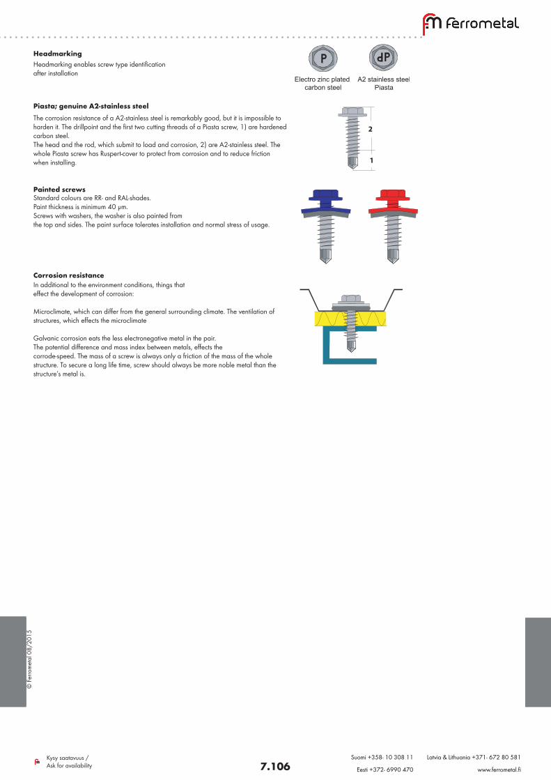
© F
erro
met
al 0
8/20
15
7.106Kysy saatavuus / Ask for availability
Suomi +358- 10 308 11 Latvia & Lithuania +371- 672 80 581
Eesti +372- 6990 470 www.ferrometal.fi
HeadmarkingHeadmarking enables screw type identification after installation
A2 stainless steelPiasta
Electro zinc plated carbon steel
Pias
2
1
Piasta; genuine A2-stainless steel The corrosion resistance of a A2-stainless steel is remarkably good, but it is impossible to harden it. The drillpoint and the first two cutting threads of a Piasta screw, 1) are hardened carbon steel. The head and the rod, which submit to load and corrosion, 2) are A2-stainless steel. The whole Piasta screw has Ruspert-cover to protect from corrosion and to reduce friction when installing.
Ruostumaton A2Sinkitty hiiliteräs Pias Piast a
2
1
Painted screws Standard colours are RR- and RAL-shades.Paint thickness is minimum 40 µm.Screws with washers, the washer is also painted from the top and sides. The paint surface tolerates installation and normal stress of usage.
Ruostumaton A2Sinkitty hiiliteräs Pias Piast a
2
1
Corrosion resistance In additional to the environment conditions, things that effect the development of corrosion:
Microclimate, which can differ from the general surrounding climate. The ventilation of structures, which effects the microclimate
Galvanic corrosion eats the less electronegative metal in the pair. The potential difference and mass index between metals, effects the corrode-speed. The mass of a screw is always only a friction of the mass of the whole structure. To secure a long life time, screw should always be more noble metal than the structure’s metal is.
Ruostumaton A2Sinkitty hiiliteräs Pias Piast a
2
1
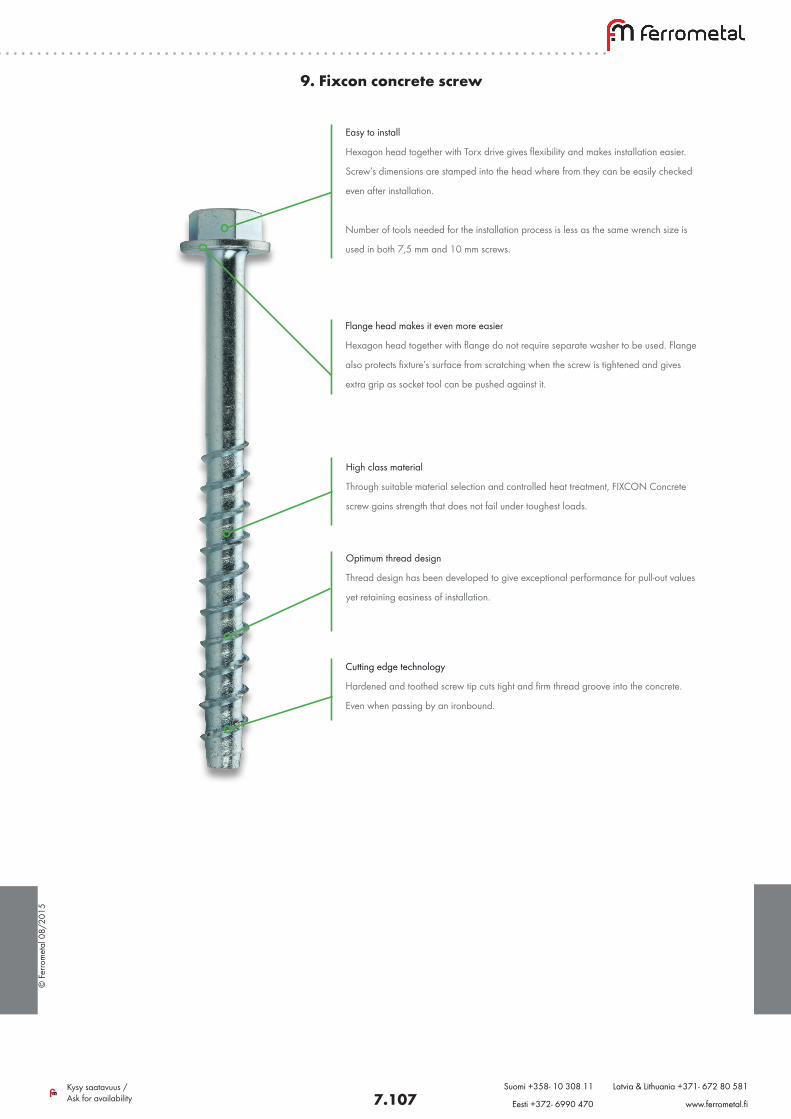
© F
erro
met
al 0
8/20
15
7.107Kysy saatavuus / Ask for availability
Suomi +358- 10 308 11 Latvia & Lithuania +371- 672 80 581
Eesti +372- 6990 470 www.ferrometal.fi
9. Fixcon concrete screw
Easy to install
Hexagon head together with Torx drive gives flexibility and makes installation easier.
Screw’s dimensions are stamped into the head where from they can be easily checked
even after installation.
Number of tools needed for the installation process is less as the same wrench size is
used in both 7,5 mm and 10 mm screws.
Flange head makes it even more easier
Hexagon head together with flange do not require separate washer to be used. Flange
also protects fixture’s surface from scratching when the screw is tightened and gives
extra grip as socket tool can be pushed against it.
Optimum thread design
Thread design has been developed to give exceptional performance for pull-out values
yet retaining easiness of installation.
Cutting edge technology
Hardened and toothed screw tip cuts tight and firm thread groove into the concrete.
Even when passing by an ironbound.
High class material
Through suitable material selection and controlled heat treatment, FIXCON Concrete
screw gains strength that does not fail under toughest loads.
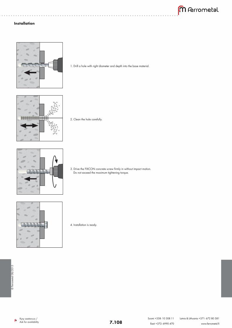
© F
erro
met
al 0
8/20
15
7.108Kysy saatavuus / Ask for availability
Suomi +358- 10 308 11 Latvia & Lithuania +371- 672 80 581
Eesti +372- 6990 470 www.ferrometal.fi
Installation
1. Drill a hole with right diameter and depth into the base material.
2. Clean the hole carefully.
3. Drive the FIXCON concrete screw firmly in without impact motion. Do not exceed the maximum tightening torque.
4. Installation is ready.
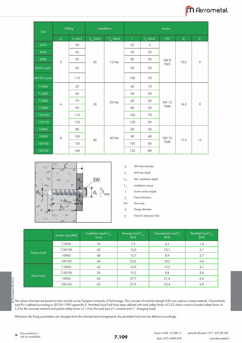
© F
erro
met
al 0
8/20
15
7.109Kysy saatavuus / Ask for availability
Suomi +358- 10 308 11 Latvia & Lithuania +371- 672 80 581
Eesti +372- 6990 470 www.ferrometal.fi
L
df
SW
Tinst
dc
d0
d0 Drill hole diameter
h1 Drill hole depth
hinst Min. installation depth
Tinst Installation torque
L Screw anchor length
tfix Fixture thickness
SW Drive size
df Flange diameter
dc Fixture’s clearance hole
SizeDrilling Installation Anchor
d0 h1 (min) hinst (min) Tinst (max) L tfix (max) SW df dc
6X35
5
50
30 12 Nm
35 5
SW 8 TX25 10,5 9
6X50 65 50 20
6X80 95 80 50
6X50 c-sunk. 65 50 20
6X100 c-sunk. 115 100 70
7,5X40
6
55
30 20 Nm
40 10
SW 13 TX40 16,5 9
7,5X50 65 50 20
7,5X60 75 60 30
7,5X80 95 80 50
7,5X100 115 100 70
7,5X120 135 120 90
10X60
8
80
40 40 Nm
60 20
SW 13 TX40 17,5 12
10X80 100 80 40
10X100 120 100 60
10X120 140 120 80
Anchor size [dXL] Installation depth hinst [mm]
Average load Fmax [kN]
Characteristic load Fk [kN]
Permitted load Fsall [kN]
Tension load
7,5X50 30 7,3 4,5 1,4
7,5X100 45 15,0 10,1 3,1
10X60 40 12,7 8,9 2,7
10X120 60 23,6 18,2 5,6
Shear load
7,5X50 45 14,9 13,3 4,1
7,5X100 55 15,2 9,8 3,0
10X60 45 27,7 21,4 6,6
10X120 65 27,9 22,4 6,9
The values informed are based on tests carried out by Tampere University of Technology. The concrete of nominal strength K30 was used as a base material. Characteristic load Fk is defined according to SFS EN 1990 appendix D. Permitted load Fsall have been defined with total safety factor of 3,22 which consist of partial safety factor of 2,3 for the concrete material and partial safety factor of 1,4 for the load type (½ constant and ½ changing load).
Whenever the fixing parameters are changed from the informed test arrangements, the permitted load must be defined accordingly.
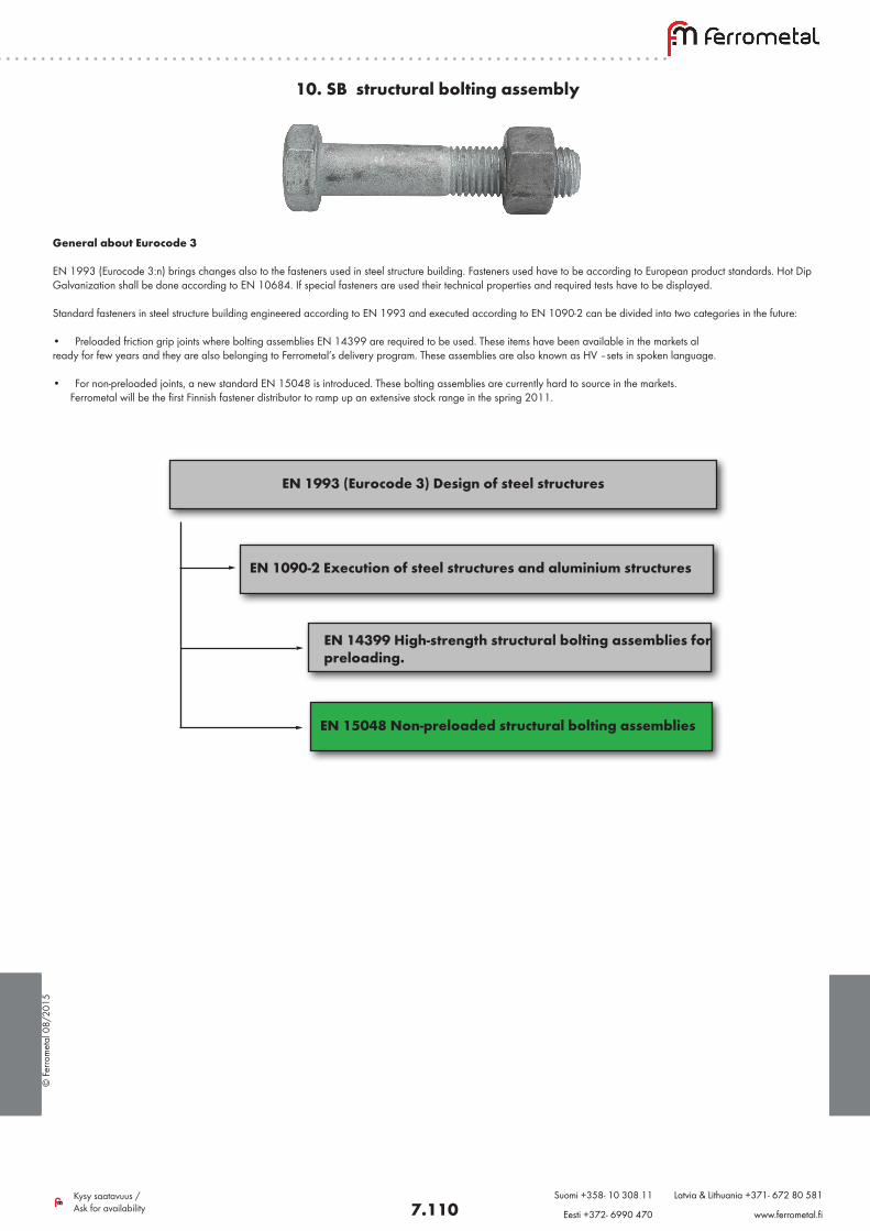
© F
erro
met
al 0
8/20
15
7.110Kysy saatavuus / Ask for availability
Suomi +358- 10 308 11 Latvia & Lithuania +371- 672 80 581
Eesti +372- 6990 470 www.ferrometal.fi
10. SB structural bolting assembly
General about Eurocode 3
EN 1993 (Eurocode 3:n) brings changes also to the fasteners used in steel structure building. Fasteners used have to be according to European product standards. Hot Dip Galvanization shall be done according to EN 10684. If special fasteners are used their technical properties and required tests have to be displayed.
Standard fasteners in steel structure building engineered according to EN 1993 and executed according to EN 1090-2 can be divided into two categories in the future:
• Preloaded friction grip joints where bolting assemblies EN 14399 are required to be used. These items have been available in the markets al ready for few years and they are also belonging to Ferrometal’s delivery program. These assemblies are also known as HV –sets in spoken language.
• For non-preloaded joints, a new standard EN 15048 is introduced. These bolting assemblies are currently hard to source in the markets. Ferrometal will be the first Finnish fastener distributor to ramp up an extensive stock range in the spring 2011.
EN 1993 (Eurocode 3) Design of steel structures
EN 1090-2 Execution of steel structures and aluminium structures
EN 14399 High-strength structural bolting assemblies for preloading.
EN 15048 Non-preloaded structural bolting assemblies
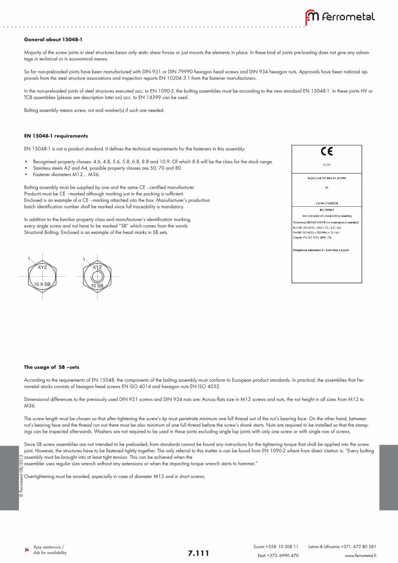
© F
erro
met
al 0
8/20
15
7.111Kysy saatavuus / Ask for availability
Suomi +358- 10 308 11 Latvia & Lithuania +371- 672 80 581
Eesti +372- 6990 470 www.ferrometal.fi
General about 15048-1
Majority of the screw joints in steel structures bears only static shear forces or just mounts the elements in place. In these kind of joints pre-loading does not give any advan-tage in technical or in economical means.
So far non-preloaded joints have been manufactured with DIN 931 or DIN 79990 hexagon head screws and DIN 934 hexagon nuts. Approvals have been national ap-provals from the steel structure associations and inspection reports EN 10204 3.1 from the fastener manufacturers. In the non-preloaded joints of steel structures executed acc. to EN 1090-2, the bolting assemblies must be according to the new standard EN 15048-1. In these joints HV or TCB assemblies (please see description later on) acc. to EN 14399 can be used.
Bolting assembly means screw, nut and washer(s) if such are needed.
EN 15048-1 requirements
EN 15048-1 is not a product standard. It defines the technical requirements for the fasteners in this assembly:
• Recognised property classes: 4.6, 4.8, 5.6, 5.8, 6.8, 8.8 and 10.9. Of which 8.8 will be the class for the stock range.• Stainless steels A2 and A4, possible property classes are 50, 70 and 80. • Fastener diameters M12… M36.
Bolting assembly must be supplied by one and the same CE –certified manufacturer. Products must be CE –marked although marking just in the packing is sufficient. Enclosed is an example of a CE –marking attached into the box. Manufacturer’s production batch identification number shall be marked since full traceability is mandatory.
In addition to the familiar property class and manufacturer’s identification marking, every single screw and nut have to be marked ”SB” which comes from the words Structural Bolting. Enclosed is an example of the head marks in SB sets.
The usage of SB –sets
According to the requirements of EN 15048, the components of the bolting assembly must conform to European product standards. In practical, the assemblies that Fer-rometal stocks consists of hexagon head screws EN ISO 4014 and hexagon nuts EN ISO 4032.
Dimensional differences to the previously used DIN 931 screws and DIN 934 nuts are: Across flats size in M12 screws and nuts, the nut height in all sizes from M12 to M36.
The screw length must be chosen so that after tightening the screw’s tip must penetrate minimum one full thread out of the nut’s bearing face. On the other hand, between nut’s bearing face and the thread run out there must be also minimum of one full thread before the screw’s shank starts. Nuts are required to be installed so that the stamp-ings can be inspected afterwards. Washers are not required to be used in these joints excluding single lap joints with only one screw or with single row of screws.
Since SB screw assemblies are not intended to be preloaded, from standards cannot be found any instructions for the tightening torque that shall be applied into the screw joint. However, the structures have to be fastened tightly together. The only referral to this matter is can be found from EN 1090-2 where from direct citation is: “Every bolting assembly must be brought into at least tight tension. This can be achieved when the assembler uses regular size wrench without any extensions or when the impacting torque wrench starts to hammer.”
Overtightening must be avoided, especially in case of diameter M12 and in short screws.
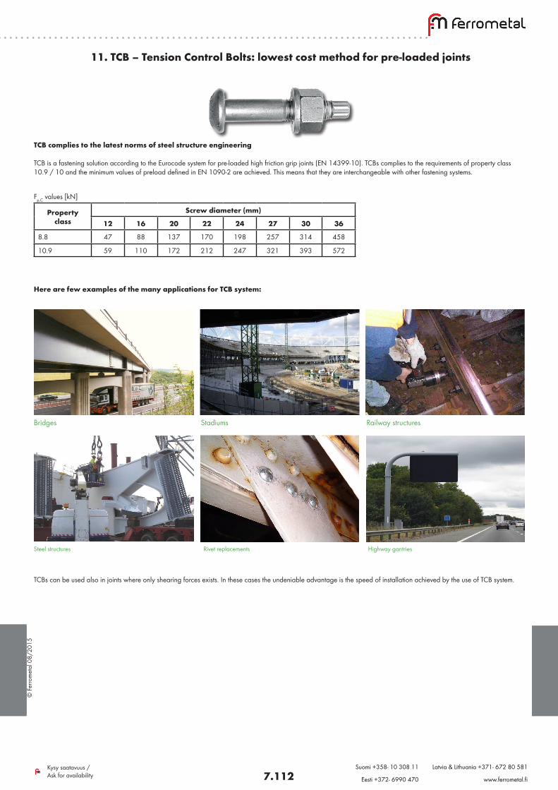
© F
erro
met
al 0
8/20
15
7.112Kysy saatavuus / Ask for availability
Suomi +358- 10 308 11 Latvia & Lithuania +371- 672 80 581
Eesti +372- 6990 470 www.ferrometal.fi
11. TCB – Tension Control Bolts: lowest cost method for pre-loaded joints
TCB complies to the latest norms of steel structure engineering
TCB is a fastening solution according to the Eurocode system for pre-loaded high friction grip joints (EN 14399-10). TCBs complies to the requirements of property class 10.9 / 10 and the minimum values of preload defined in EN 1090-2 are achieved. This means that they are interchangeable with other fastening systems.
Here are few examples of the many applications for TCB system:
Bridges Stadiums Railway structures
Steel structures Rivet replacements Highway gantries
TCBs can be used also in joints where only shearing forces exists. In these cases the undeniable advantage is the speed of installation achieved by the use of TCB system.
Fp,C values [kN]
Property class
Screw diameter (mm)
12 16 20 22 24 27 30 36
8.8 47 88 137 170 198 257 314 458
10.9 59 110 172 212 247 321 393 572
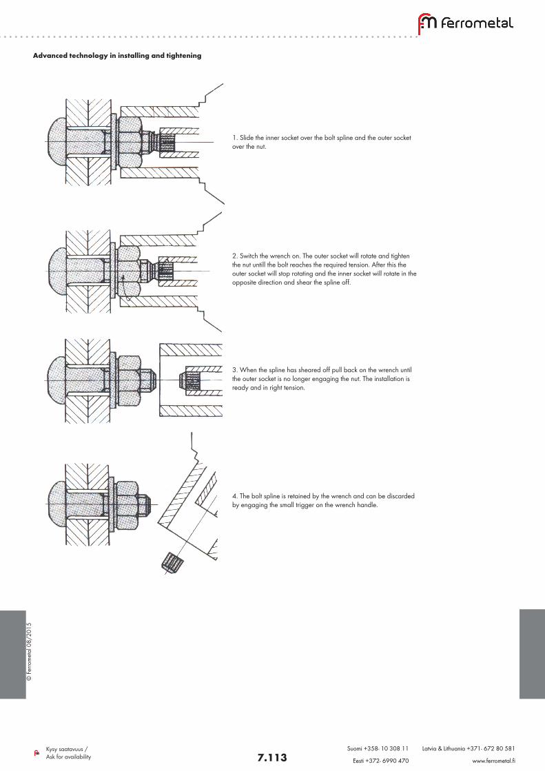
© F
erro
met
al 0
8/20
15
7.113Kysy saatavuus / Ask for availability
Suomi +358- 10 308 11 Latvia & Lithuania +371- 672 80 581
Eesti +372- 6990 470 www.ferrometal.fi
Advanced technology in installing and tightening
1. Slide the inner socket over the bolt spline and the outer socket over the nut.
2. Switch the wrench on. The outer socket will rotate and tighten the nut untill the bolt reaches the required tension. After this the outer socket will stop rotating and the inner socket will rotate in the opposite direction and shear the spline off.
3. When the spline has sheared off pull back on the wrench until the outer socket is no longer engaging the nut. The installation is ready and in right tension.
4. The bolt spline is retained by the wrench and can be discarded by engaging the small trigger on the wrench handle.
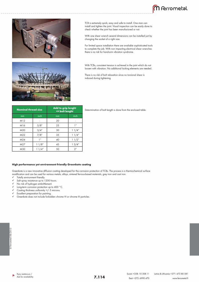
© F
erro
met
al 0
8/20
15
7.114Kysy saatavuus / Ask for availability
Suomi +358- 10 308 11 Latvia & Lithuania +371- 672 80 581
Eesti +372- 6990 470 www.ferrometal.fi
TCB is extremely quick, easy and safe to install. One man can install and tighten the joint. Visual inspection can be easily done to check whether the joint has been manufactured or not.
With one shear wrench several dimensions can be installed just by changing the socket of a right size.
For limited space installation there are available sophisticated tools to complete the job. With non impacting electrical shear wrenches there is no risk for hand-arm vibration syndrome.
With TCBs, consistent tension is achieved in the joint which do not loosen with vibration. No additional locking elements are needed.
There is no risk of bolt relaxation since no torsional shear is induced during tightening
Determination of bolt length is done from the enclosed table.Nominal thread size Add to grip lenght => bolt lenght
mm inch mm inch
M12 - 20 -
M16 5/8” 25 1”
M20 3/4” 30 1 1/4”
M22 7/8” 35 1 1/4”
M24 1” 40 1 1/2”
M27 1 1/8” 45 1 3/4”
M30 1 1/4” 50 2”
High performance yet environment friendly Greenkote coating
Greenkote is a new innovative diffusion coating developed for the corrosion protection of TCBs. The process is a thermochemical surface modification and can be used for various metals, alloys, sintered ferrous-based materials, grey iron and cast iron. Totally environment friendly. Salt spray resistance up to 1200 hours. No risk of hydrogen embrittlement. Long-term corrosion protection up to 400 °C. Coating thickness uniformity +/- 5 microns. Excellent preparation for painting. Greenkote does not include forbidden chrome VI or chrome III particles.
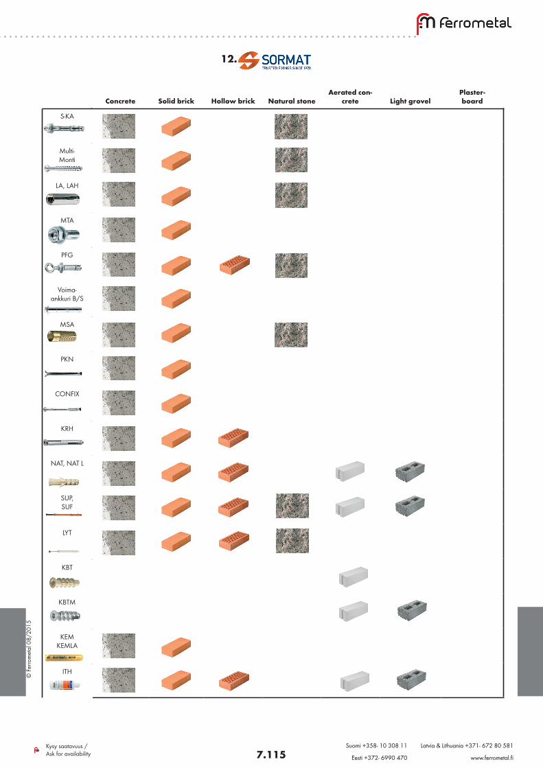
© F
erro
met
al 0
8/20
15
7.115Kysy saatavuus / Ask for availability
Suomi +358- 10 308 11 Latvia & Lithuania +371- 672 80 581
Eesti +372- 6990 470 www.ferrometal.fi
Concrete Solid brick Hollow brick Natural stone
Aerated con-crete Light grovel
Plaster- board
S-KA
Multi- Monti
LA, LAH
MTA
PFG
Voima- ankkuri B/S
MSA
PKN
CONFIX
KRH
NAT, NAT L
SUP, SUF
LYT
KBT
KBTM
KEM KEMLA
ITH
12.
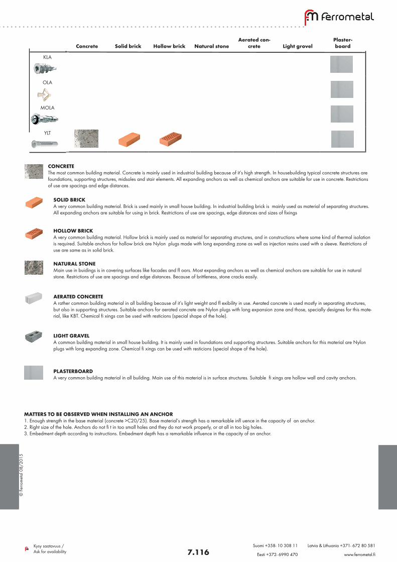
© F
erro
met
al 0
8/20
15
7.116Kysy saatavuus / Ask for availability
Suomi +358- 10 308 11 Latvia & Lithuania +371- 672 80 581
Eesti +372- 6990 470 www.ferrometal.fi
Concrete
Solid brick
Hollow brick
Natural stone
Aerated con-crete
Light grovel
Plaster- board
KLA
OLA
MOLA
YLT
CONCRETE The most common building material. Concrete is mainly used in industrial building because of it’s high strength. In housebuilding typical concrete structures are foundations, supporting structures, midsoles and stair elements. All expanding anchors as well as chemical anchors are suitable for use in concrete. Restrictions of use are spacings and edge distances.
SOLID BRICK A very common building material. Brick is used mainly in small house building. In industrial building brick is mainly used as material of separating structures. All expanding anchors are suitable for using in brick. Restrictions of use are spacings, edge distances and sizes of fixings
HOLLOW BRICK A very common building material. Hollow brick is mainly used as material for separating structures, and in constructions where some kind of thermal isolation is required. Suitable anchors for hollow brick are Nylon plugs made with long expanding zone as well as injection resins used with a sleeve. Restrictions of use are same as in solid brick.
NATURAL STONE Main use in buidings is in covering surfaces like facades and fl oors. Most expanding anchors as well as chemical anchors are suitable for use in natural stone. Restrictions of use are spacings and edge distances. Because of brittleness, stone cracks easily.
AERATED CONCRETE A rather common building material in all building because of it’s light weight and fl exibility in use. Aerated concrete is used mostly in separating structures, but also in supporting structures. Suitable anchors for aerated concrete are Nylon plugs with long expansion zone and those, specially designes for this mate-rial, like KBT. Chemical fi xings can be used with resticions (special shape of the hole).
LIGHT GRAVEL A common building material in small house building. It is mainly used in foundations and supporting structures. Suitable anchors for this material are Nylon plugs with long expanding zone. Chemical fi xings can be used with resticions (special shape of the hole).
PLASTERBOARD A very common building material in all building. Main use of this material is in surface structures. Suitable fi xings are hollow wall and cavity anchors.
MATTERS TO BE OBSERVED WHEN INSTALLING AN ANCHOR 1. Enough strength in the base material (concrete >C20/25). Base material’s strength has a remarkable infl uence in the capacity of an anchor. 2. Right size of the hole. Anchors do not fi t in too small holes and they do not work properly, or at all in too big holes. 3. Embedment depth according to instructions. Embedment depth has a remarkable influence in the capacity of an anchor.
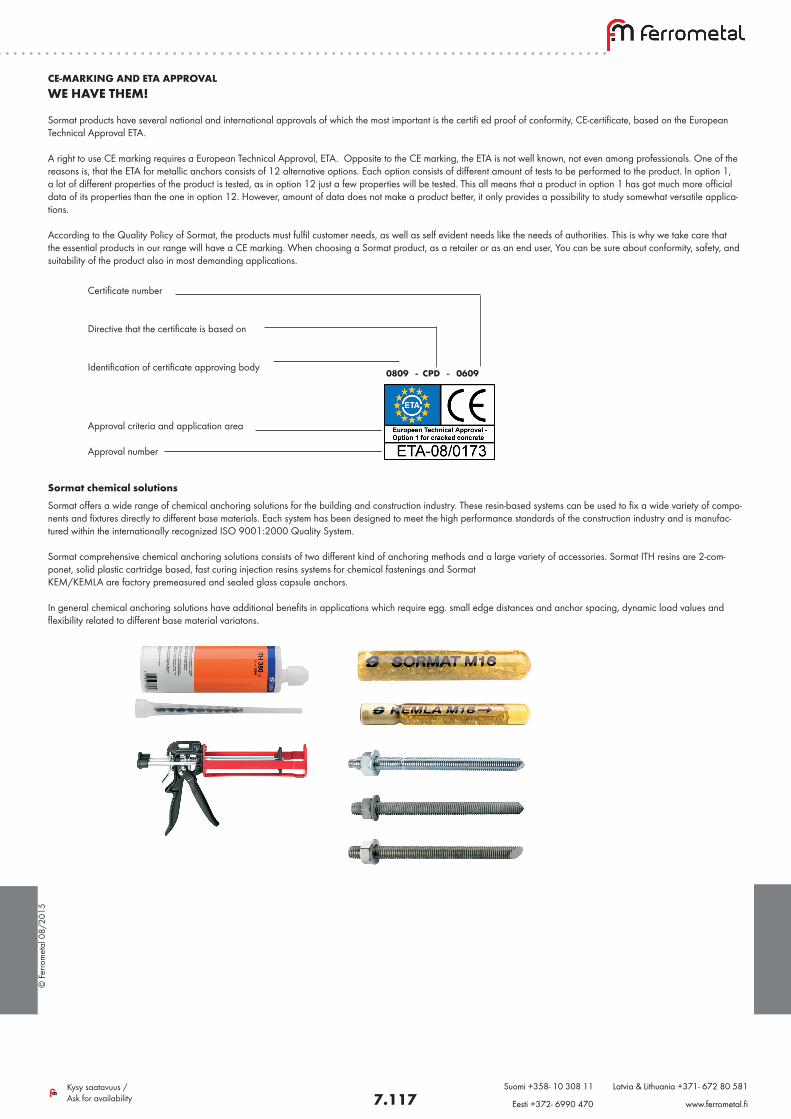
© F
erro
met
al 0
8/20
15
7.117Kysy saatavuus / Ask for availability
Suomi +358- 10 308 11 Latvia & Lithuania +371- 672 80 581
Eesti +372- 6990 470 www.ferrometal.fi
CE-MARKING AND ETA APPROVAL WE HAVE THEM! Sormat products have several national and international approvals of which the most important is the certifi ed proof of conformity, CE-certificate, based on the European Technical Approval ETA. A right to use CE marking requires a European Technical Approval, ETA. Opposite to the CE marking, the ETA is not well known, not even among professionals. One of the reasons is, that the ETA for metallic anchors consists of 12 alternative options. Each option consists of different amount of tests to be performed to the product. In option 1, a lot of different properties of the product is tested, as in option 12 just a few properties will be tested. This all means that a product in option 1 has got much more official data of its properties than the one in option 12. However, amount of data does not make a product better, it only provides a possibility to study somewhat versatile applica-tions. According to the Quality Policy of Sormat, the products must fulfil customer needs, as well as self evident needs like the needs of authorities. This is why we take care that the essential products in our range will have a CE marking. When choosing a Sormat product, as a retailer or as an end user, You can be sure about conformity, safety, and suitability of the product also in most demanding applications.
0809 - CPD - 0609
Certificate number
Directive that the certificate is based on
Identification of certificate approving body
Approval criteria and application area
Approval number
Sormat chemical solutionsSormat offers a wide range of chemical anchoring solutions for the building and construction industry. These resin-based systems can be used to fix a wide variety of compo-nents and fixtures directly to different base materials. Each system has been designed to meet the high performance standards of the construction industry and is manufac-tured within the internationally recognized ISO 9001:2000 Quality System. Sormat comprehensive chemical anchoring solutions consists of two different kind of anchoring methods and a large variety of accessories. Sormat ITH resins are 2-com-ponet, solid plastic cartridge based, fast curing injection resins systems for chemical fastenings and Sormat KEM/KEMLA are factory premeasured and sealed glass capsule anchors. In general chemical anchoring solutions have additional benefits in applications which require egg. small edge distances and anchor spacing, dynamic load values and flexibility related to different base material variatons.
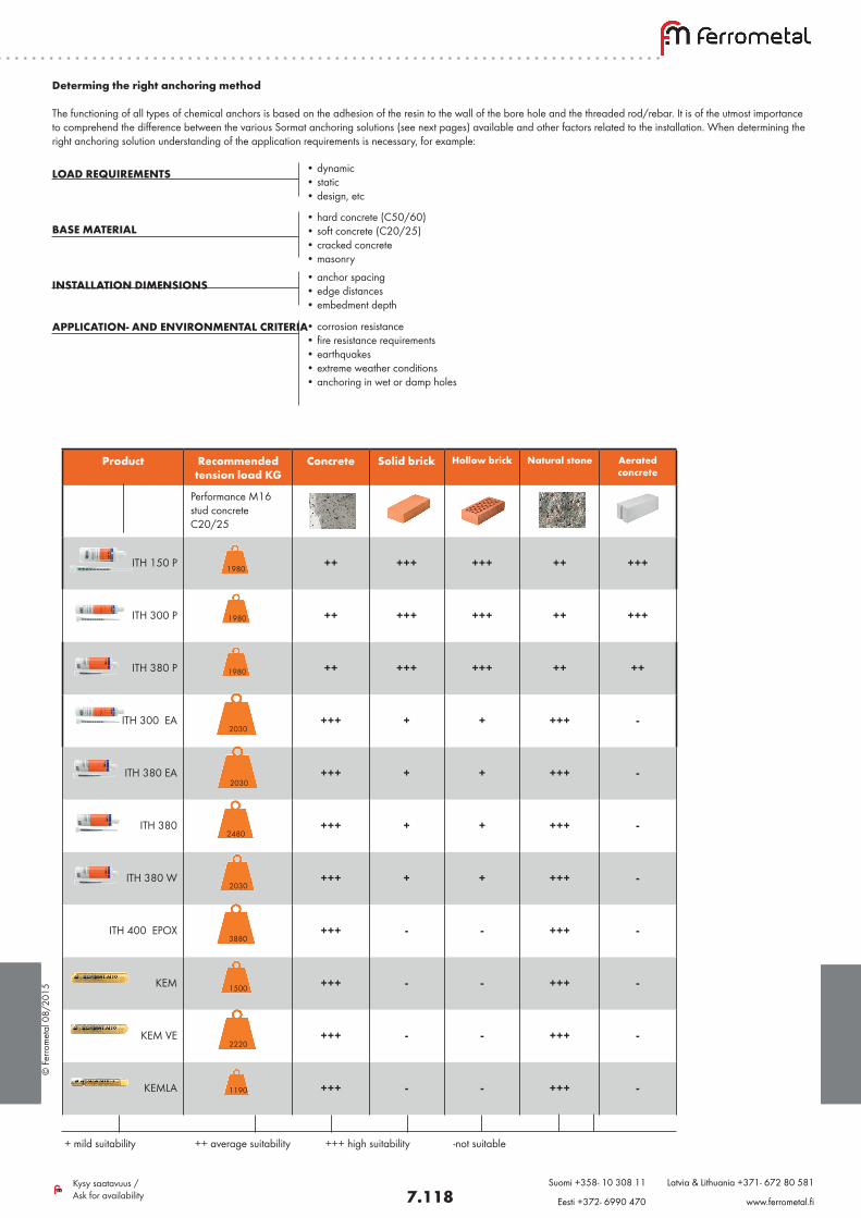
© F
erro
met
al 0
8/20
15
7.118Kysy saatavuus / Ask for availability
Suomi +358- 10 308 11 Latvia & Lithuania +371- 672 80 581
Eesti +372- 6990 470 www.ferrometal.fi
Determing the right anchoring method The functioning of all types of chemical anchors is based on the adhesion of the resin to the wall of the bore hole and the threaded rod/rebar. It is of the utmost importance to comprehend the difference between the various Sormat anchoring solutions (see next pages) available and other factors related to the installation. When determining the right anchoring solution understanding of the application requirements is necessary, for example:
LOAD REQUIREMENTS BASE MATERIAL
INSTALLATION DIMENSIONS APPLICATION- AND ENVIRONMENTAL CRITERIA
• dynamic • static • design, etc
• hard concrete (C50/60) • soft concrete (C20/25) • cracked concrete • masonry• anchor spacing • edge distances • embedment depth
• corrosion resistance • fire resistance requirements • earthquakes • extreme weather conditions • anchoring in wet or damp holes
Product Recommended tension load KG
Concrete Solid brick Hollow brick Natural stone Aerated concrete
Performance M16 stud concrete C20/25
ITH 150 P
++
+++
+++
++
+++
ITH 300 P
++
+++ +++ ++ +++
ITH 380 P
++ +++ +++ ++ ++
ITH 300 EA
+++
+
+
+++
-
ITH 380 EA +++ + + +++ -
ITH 380
+++
+
+
+++
-
ITH 380 W
+++ + + +++ -
ITH 400 EPOX +++ - - +++ -
KEM +++ - - +++ -
KEM VE +++ - - +++ -
KEMLA +++ - - +++ -
+ mild suitability ++ average suitability +++ high suitability -not suitable
1980
2030
2480
2030
1500
2220
1190
1980
1980
2030
3880
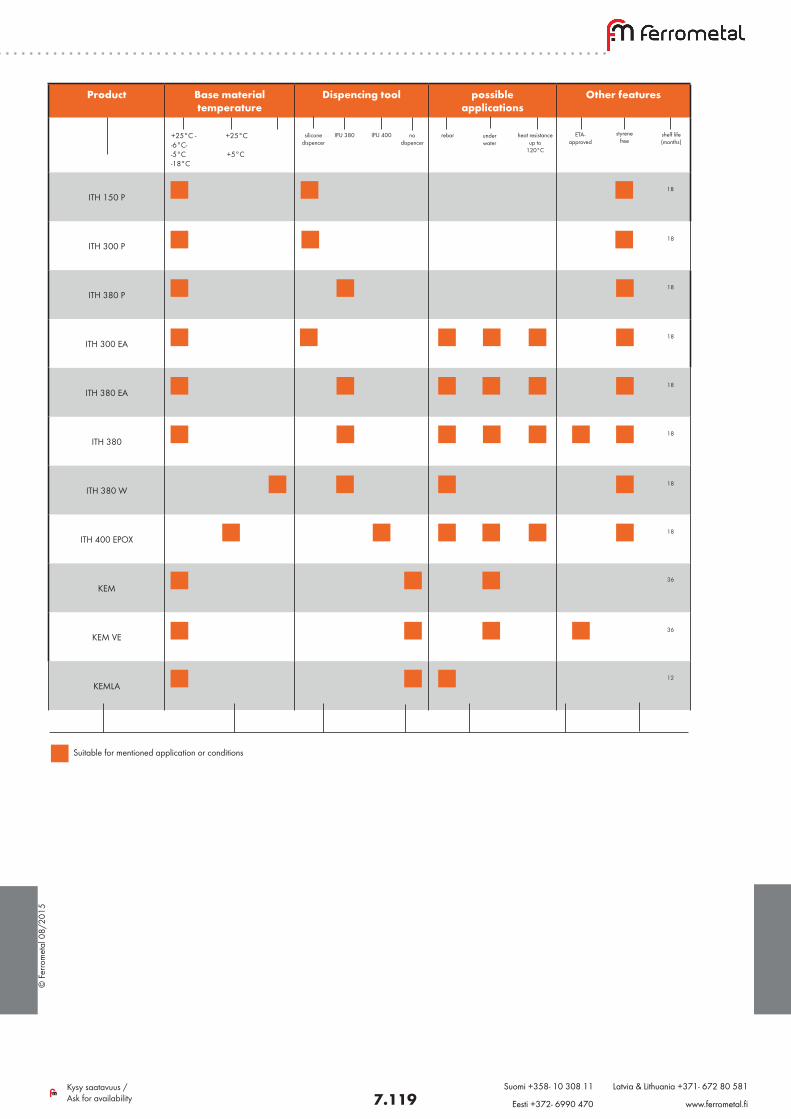
© F
erro
met
al 0
8/20
15
7.119Kysy saatavuus / Ask for availability
Suomi +358- 10 308 11 Latvia & Lithuania +371- 672 80 581
Eesti +372- 6990 470 www.ferrometal.fi
Product Base material temperature
Dispencing tool possible applications
Other features
+25°C - +25°C -6°C- -5°C +5°C -18°C
ITH 150 P
ITH 300 P
ITH 380 P
ITH 300 EA
ITH 380 EA
ITH 380
ITH 380 W
ITH 400 EPOX
KEM
KEM VE
KEMLA
Suitable for mentioned application or conditions
IPU 380
18
18
18
18
18
36
36
12
18
18
18
IPU 400 silicone dispencer
rebar under water
heat resistance up to
120°C
ETA- approved
styrene free
shelf life(months)
no dispencer
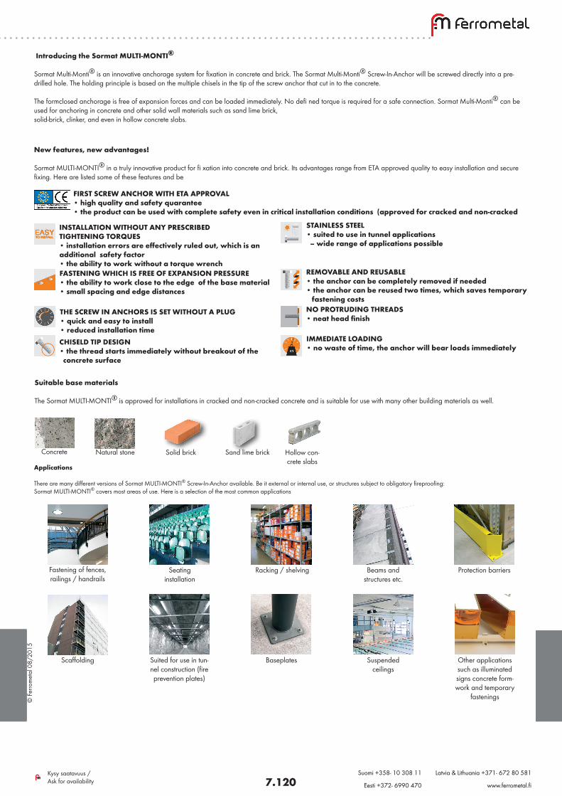
© F
erro
met
al 0
8/20
15
7.120Kysy saatavuus / Ask for availability
Suomi +358- 10 308 11 Latvia & Lithuania +371- 672 80 581
Eesti +372- 6990 470 www.ferrometal.fi
Introducing the Sormat MULTI-MONTI® Sormat Multi-Monti® is an innovative anchorage system for fixation in concrete and brick. The Sormat Multi-Monti® Screw-In-Anchor will be screwed directly into a pre-drilled hole. The holding principle is based on the multiple chisels in the tip of the screw anchor that cut in to the concrete. The formclosed anchorage is free of expansion forces and can be loaded immediately. No defi ned torque is required for a safe connection. Sormat Multi-Monti® can be used for anchoring in concrete and other solid wall materials such as sand lime brick, solid-brick, clinker, and even in hollow concrete slabs.
New features, new advantages! Sormat MULTI-MONTI® in a truly innovative product for fi xation into concrete and brick. Its advantages range from ETA approved quality to easy installation and secure fixing. Here are listed some of these features and be
FIRST SCREW ANCHOR WITH ETA APPROVAL • high quality and safety quarantee • the product can be used with complete safety even in critical installation conditions (approved for cracked and non-cracked
INSTALLATION WITHOUT ANY PRESCRIBED TIGHTENING TORQUES • installation errors are effectively ruled out, which is an additional safety factor • the ability to work without a torque wrenchFASTENING WHICH IS FREE OF EXPANSION PRESSURE • the ability to work close to the edge of the base material • small spacing and edge distances
THE SCREW IN ANCHORS IS SET WITHOUT A PLUG • quick and easy to install • reduced installation timeCHISELD TIP DESIGN • the thread starts immediately without breakout of the concrete surface
STAINLESS STEEL • suited to use in tunnel applications – wide range of applications possible
REMOVABLE AND REUSABLE • the anchor can be completely removed if needed • the anchor can be reused two times, which saves temporary fastening costsNO PROTRUDING THREADS • neat head finish
IMMEDIATE LOADING • no waste of time, the anchor will bear loads immediately
Suitable base materials The Sormat MULTI-MONTI® is approved for installations in cracked and non-cracked concrete and is suitable for use with many other building materials as well.
Applications There are many different versions of Sormat MULTI-MONTI® Screw-In-Anchor available. Be it external or internal use, or structures subject to obligatory fireproofing: Sormat MULTI-MONTI® covers most areas of use. Here is a selection of the most common applications
Concrete Natural stone Solid brick Sand lime brick Hollow con-crete slabs
Fastening of fences, railings / handrails
Seating installation
Racking / shelving Beams and structures etc.
Protection barriers
Scaffolding Suited for use in tun-nel construction (fire prevention plates)
Baseplates Suspended ceilings
Other applications such as illuminated signs concrete form-work and temporary
fastenings
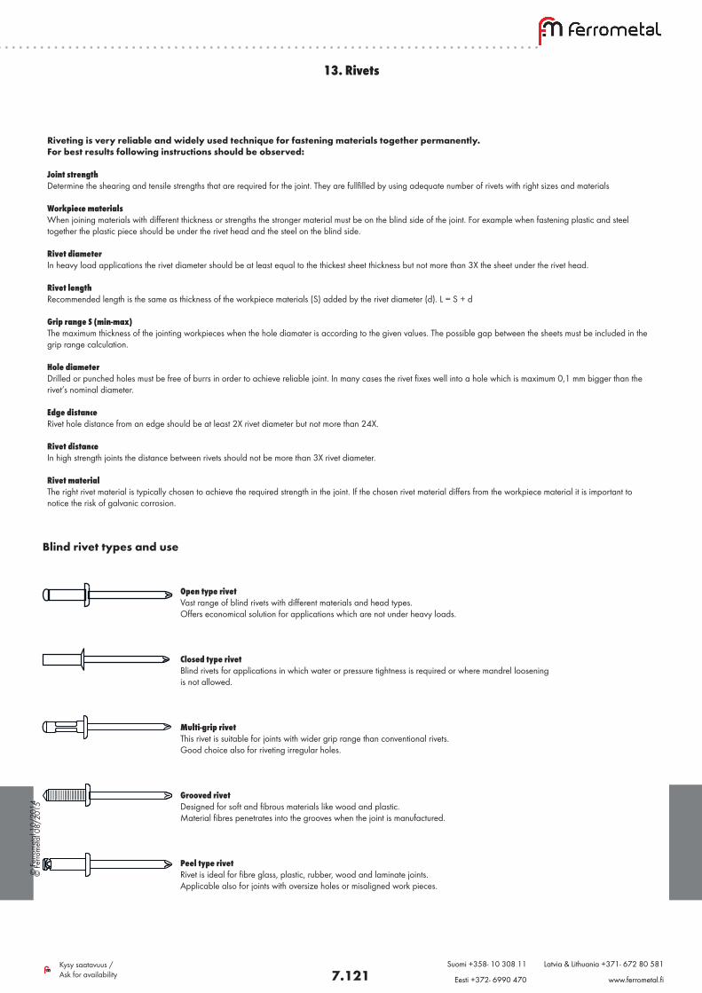
© F
erro
met
al 0
8/20
15
7.121Kysy saatavuus / Ask for availability
Suomi +358- 10 308 11 Latvia & Lithuania +371- 672 80 581
Eesti +372- 6990 470 www.ferrometal.fi
13. Rivets
Riveting is very reliable and widely used technique for fastening materials together permanently.For best results following instructions should be observed:
Joint strengthDetermine the shearing and tensile strengths that are required for the joint. They are fullfilled by using adequate number of rivets with right sizes and materials
Workpiece materialsWhen joining materials with different thickness or strengths the stronger material must be on the blind side of the joint. For example when fastening plastic and steel together the plastic piece should be under the rivet head and the steel on the blind side.
Rivet diameterIn heavy load applications the rivet diameter should be at least equal to the thickest sheet thickness but not more than 3X the sheet under the rivet head.
Rivet lengthRecommended length is the same as thickness of the workpiece materials (S) added by the rivet diameter (d). L = S + d
Grip range S (min-max)The maximum thickness of the jointing workpieces when the hole diamater is according to the given values. The possible gap between the sheets must be included in the grip range calculation.
Hole diameterDrilled or punched holes must be free of burrs in order to achieve reliable joint. In many cases the rivet fixes well into a hole which is maximum 0,1 mm bigger than the rivet’s nominal diameter.
Edge distanceRivet hole distance from an edge should be at least 2X rivet diameter but not more than 24X.
Rivet distanceIn high strength joints the distance between rivets should not be more than 3X rivet diameter.
Rivet materialThe right rivet material is typically chosen to achieve the required strength in the joint. If the chosen rivet material differs from the workpiece material it is important to notice the risk of galvanic corrosion.
Open type rivetVast range of blind rivets with different materials and head types. Offers economical solution for applications which are not under heavy loads. Closed type rivetBlind rivets for applications in which water or pressure tightness is required or where mandrel loosening is not allowed.
Multi-grip rivetThis rivet is suitable for joints with wider grip range than conventional rivets. Good choice also for riveting irregular holes.
Grooved rivetDesigned for soft and fibrous materials like wood and plastic.Material fibres penetrates into the grooves when the joint is manufactured.
Peel type rivetRivet is ideal for fibre glass, plastic, rubber, wood and laminate joints. Applicable also for joints with oversize holes or misaligned work pieces.
Blind rivet types and use
© F
erro
met
al 1
0/20
14
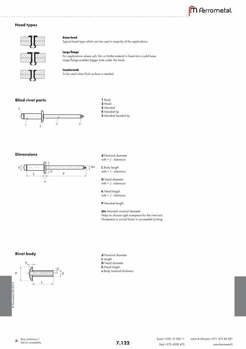
© F
erro
met
al 0
8/20
15
7.122Kysy saatavuus / Ask for availability
Suomi +358- 10 308 11 Latvia & Lithuania +371- 672 80 581
Eesti +372- 6990 470 www.ferrometal.fi
Dome headTypical head type which can be used in majority of the applications.
Large flangeFor applications where soft, thin or brittle material is fixed into a solid base. Large flange enables bigger hole under the head.
CountersunkTo be used when flush surface is needed.
Head types
1 Body2 Head3 Mandrel4 Mandrel tip5 Mandrel beveled tip
d Nominal diameter with + / - tolerance
L Body lengthwith + / - tolerance
D Head diameterwith + / - tolerance
k Head heightwith + / - tolerance
P Mandrel length
dm Mandrel nominal diameterHelps to choose right nosepiece for the rivet tool.Nosepiece is crucial factor in succeeded jointing.
d Nominal diameterL LengthD Head diameterk Head heights Body material thickness
L PD
k
dmd
5321
4
Blind rivet parts
Dimensions
Rivet body
k
D
L
d
s
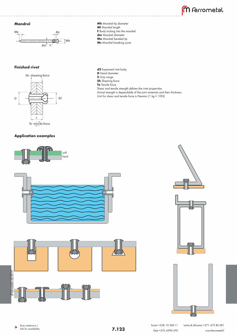
© F
erro
met
al 0
8/20
15
7.123Kysy saatavuus / Ask for availability
Suomi +358- 10 308 11 Latvia & Lithuania +371- 672 80 581
Eesti +372- 6990 470 www.ferrometal.fi
Mh Mandrel tip diameterMl Mandrel lengthF Body locking into the mandreldm Mandrel diameterMe Mandrel beveled tipMc Mandrel breaking zone
d2 Expansed rivet body D Head diameterS Grip range Sh Shearing force Te Tensile force Shear and tensile strength defines the rivet properrtiesActual strength is dependable of the joint materials and their thicknessUnit for shear and tensile force is Newton (1 kg ≈ 10N)
s
D d2
Te- tencile force
Sh- shearing force
Mandrel
Finished rivet
Me Mc
Mhdm F
Application examples
soft hard
© F
erro
met
al 1
0/20
14
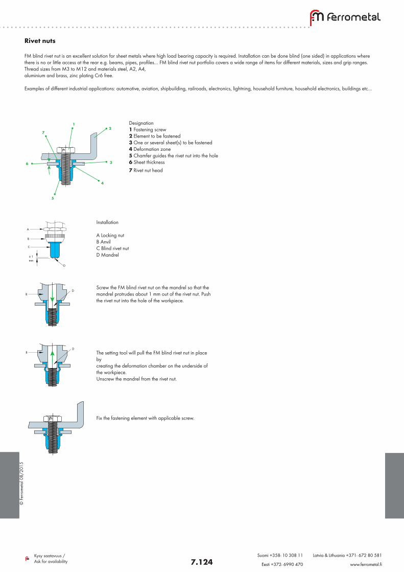
© F
erro
met
al 0
8/20
15
7.124Kysy saatavuus / Ask for availability
Suomi +358- 10 308 11 Latvia & Lithuania +371- 672 80 581
Eesti +372- 6990 470 www.ferrometal.fi
Designation1 Fastening screw2 Element to be fastened3 One or several sheet(s) to be fastened4 Deformation zone5 Chamfer guides the rivet nut into the hole6 Sheet thickness7 Rivet nut head
C
B
A
± 1mm
D
DB
DB
1
7
6
5
4
3
2
Installation
A Locking nutB AnvilC Blind rivet nutD Mandrel
Screw the FM blind rivet nut on the mandrel so that the mandrel protrudes about 1 mm out of the rivet nut. Push the rivet nut into the hole of the workpiece.
The setting tool will pull the FM blind rivet nut in place bycreating the deformation chamber on the underside of the workpiece.Unscrew the mandrel from the rivet nut.
Fix the fastening element with applicable screw.
Rivet nuts FM blind rivet nut is an excellent solution for sheet metals where high load bearing capacity is required. Installation can be done blind (one sided) in applications where there is no or little access at the rear e.g. beams, pipes, profiles… FM blind rivet nut portfolio covers a wide range of items for different materials, sizes and grip ranges. Thread sizes from M3 to M12 and materials steel, A2, A4, aluminium and brass, zinc plating Cr6 free.
Examples of different industrial applications: automotive, aviation, shipbuilding, railroads, electronics, lightning, household furniture, household electronics, buildings etc…
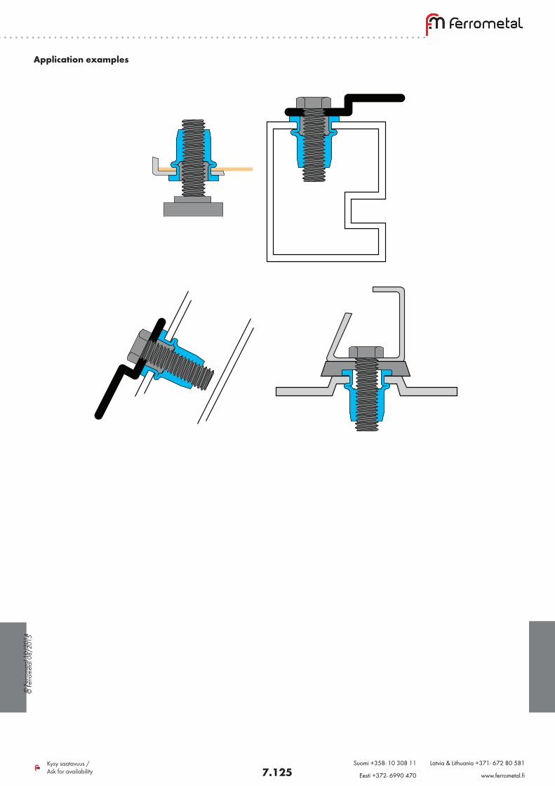
© F
erro
met
al 0
8/20
15
7.125Kysy saatavuus / Ask for availability
Suomi +358- 10 308 11 Latvia & Lithuania +371- 672 80 581
Eesti +372- 6990 470 www.ferrometal.fi
Application examples
© F
erro
met
al 1
0/20
14
© F
erro
met
al 0
8/20
15
7.126Kysy saatavuus / Ask for availability
Suomi +358- 10 308 11 Latvia & Lithuania +371- 672 80 581
Eesti +372- 6990 470 www.ferrometal.fi
© F
erro
met
al 1
0/20
14