Embed Size (px)
Citation preview

IVES Customer Service:1-877-613-87661-877-424-8494 FAX
©2003 Ingersoll-Rand Form IV-2001C Rev. 4/03 Printed in USA
DIVISION
8
i
Table of Contents
General InformationIndex by Product Description . . . . . . . . . . . . . . . . . . . . . . . . . . . . . . . . . . . . . . . . . . . . . . . . . . . . . . . . . . .ii, iii Alphanumeric Index . . . . . . . . . . . . . . . . . . . . . . . . . . . . . . . . . . . . . . . . . . . . . . . . . . . . . . . . . . . . . . . .iv – viiFinish List . . . . . . . . . . . . . . . . . . . . . . . . . . . . . . . . . . . . . . . . . . . . . . . . . . . . . . . . . . . . . . . . . . . . . . . .viii, ixPackaging, Handing . . . . . . . . . . . . . . . . . . . . . . . . . . . . . . . . . . . . . . . . . . . . . . . . . . . . . . . . . . . . . . . . . . . .xIves & Glynn-Johnson Product Conversions . . . . . . . . . . . . . . . . . . . . . . . . . . . . . . . . . . . . . . . . . . .xi, xii, xiii
Product Category Section
Flush Bolts, Coordinators . . . . . . . . . . . . . . . . . . . . . . . . . . . . . . . . . . . . . . . . . . . . . . . . . . . . . . . . . . . . . . . .APivots . . . . . . . . . . . . . . . . . . . . . . . . . . . . . . . . . . . . . . . . . . . . . . . . . . . . . . . . . . . . . . . . . . . . . . . . . . . . . . .BArchitectural Door Trim . . . . . . . . . . . . . . . . . . . . . . . . . . . . . . . . . . . . . . . . . . . . . . . . . . . . . . . . . . . . . . . . . .CFloor Stops, Wall Stops, Bumpers, Silencers . . . . . . . . . . . . . . . . . . . . . . . . . . . . . . . . . . . . . . . . . . . . . . . . .DSurface Bolts, Dutch Door Bolts, Door Guards . . . . . . . . . . . . . . . . . . . . . . . . . . . . . . . . . . . . . . . . . . . . . . . .EExterior Door Hardware . . . . . . . . . . . . . . . . . . . . . . . . . . . . . . . . . . . . . . . . . . . . . . . . . . . . . . . . . . . . . . . . . .FLatches, Catches & Mortise Door Bolts . . . . . . . . . . . . . . . . . . . . . . . . . . . . . . . . . . . . . . . . . . . . . . . . . . . . .G Hooks & Brackets . . . . . . . . . . . . . . . . . . . . . . . . . . . . . . . . . . . . . . . . . . . . . . . . . . . . . . . . . . . . . . . . . . . . . .HWindow Hardware . . . . . . . . . . . . . . . . . . . . . . . . . . . . . . . . . . . . . . . . . . . . . . . . . . . . . . . . . . . . . . . . . . . . . .IHinges . . . . . . . . . . . . . . . . . . . . . . . . . . . . . . . . . . . . . . . . . . . . . . . . . . . . . . . . . . . . . . . . . . . . . . . . . . . . . . .JCabinet Knobs & Pulls . . . . . . . . . . . . . . . . . . . . . . . . . . . . . . . . . . . . . . . . . . . . . . . . . . . . . . . . . . . . . . . . . .KHobby Hardware . . . . . . . . . . . . . . . . . . . . . . . . . . . . . . . . . . . . . . . . . . . . . . . . . . . . . . . . . . . . . . . . . . . . . . .L
ii
Index by Product Description
A Page(s)Adjustable catch . . . . . . . . . . . . . . . . . . . . .I6Adjuster, casement . . . . . . . . . . . . . . . .I4, I5Applied stop . . . . . . . . . . . . . . . . . . . . . . .G4Architectural door trim . . . . . . . . . . .C1-C17Armor plates . . . . . . . . . . . . . . . . . . . . . .C14Automatic floor holder . . . . . . . . . . .D9, D10Automatic flush bolt . . . . . . . . . . . . . .A1, A2Automatic wall holder . . . . . . . . . . . . . . .D19Auxiliary pusher . . . . . . . . . . . . . . . . . . . .G6
BBack plate, knob . . . . . . . . . . . . . . . . . . . .K1Back plate, mail slot . . . . . . . . . . . .F14-F17Ball catch . . . . . . . . . . . . .G5, G6, G11, G12Base door stop . . . . . . . . . . . . . . . .D22, D23Bar window lift . . . . . . . . . . . . . . . . . . . . . .I3Barrel bolt (HH*) . . . . . . . . . . . . . . . . . . . .L1Beaded pull . . . . . . . . . . . . . . . . . . . . . . . .K3Blind holdbacks . . . . . . . . . . . . . . . . . . . . .I6Bolt, door . . . . . . . . . . . . . . . . . . . . .G14, K7Bolt, dutch door . . . . . . . . . . . . . . . . . . .E10Bolt, flush . . . . . . . . . . . . . .A1-A8, A10, A11Bolt, mortise . . . . . . . . . . . . . . . . . . . . . .G14Bolt, security . . . . . . . . . . . . . . . . . . . . . .E11Bolt, surface . . . . . . . . . . . . . . . . . . . .E1-E9Bracket (HH*) . . . . . . . . . . . . . . . . . . . . . .L7Bracket, handrail . . . . . . . . . . . . . . . .H1, H2Bumper, roller . . . . . . . . . . . . . . . . . . . . .D22Bumper, wall . . . . . . . . . . . . . . . . . .D13-D18
CCabinet catch . . . . . . . . . . . . . . . . . . . . . .K4Cabinet knob (HH*) . . . . . . . . . . . . . . . . .L2Cabinet knob . . . . . . . . . . . . . . . . . . .K1, K2Cabinet latch . . . . . . . . . . . . . . . . . . .G5, G6 Carry bar . . . . . . . . . . . . . . . . . . . . . . . . .A16Casement adjuster . . . . . . . . . . . . . . . .I4, I5Casement fastener . . . . . . . . . . . . . . . . . . .I4Catch, adjustable . . . . . . . . . . . . . . . . . . . .I6Catch, ball . . . . . . . . . . . .G5, G6, G11, G12Catch, cabinet . . . . . . . . . . . . . . . . . . . . . .K4Catch, draw (HH*) . . . . . . . . . . . . . . .L7, L8Catch, friction (HH*) . . . . . . . . . . . . . . . . .L1Catch, magnetic . . . . . . . . . . . . . . . . .G7, G8Catch, roller . . . . . . . . . . . . . . . . . . .G9, G10Catch, snap (HH*) . . . . . . . . . . . . . . . . . .L8Catch, transom . . . . . . . . . . . . . . . . . . . . . .I5Ceiling hook . . . . . . . . . . . . . . . . . . . . . . .H5
Center hung pivot . . . . . . . . . . . . . .B16-B20Chain door guard . . . . . . . . . . . . . . . . . .E12Chain, transom . . . . . . . . . . . . . . . . . . . . .I5Chest handle (HH*) . . . . . . . . . . . . . . . . .L8Chime, door . . . . . . . . . . . . . . . . . . . . . . .F5Closer, pneumatic door . . . . . . . . . . . . . .F18Closet pole sockets . . . . . . . . . . . . . . . . .H6Coat and hat hook . . . . . . . . . . . . . . . . .H3-5Combination rollerlatch/applied stop . . . . . . . . . . . . . . . . . . .G2Constant latching flush bolt . . . . . . . .A3, A4Continuous hinge (HH*) . . . . . . . . . . . . . .L2Coordinator, bar . . . . . . . . . . . . . . .A12-A15Coordinator, gravity arm . . . . . . . . . . . . .A16Corners (HH*) . . . . . . . . . . . . . . . . . . . . . .L7Countersunk washer . . . . . . . . . . . . . . . . .I6Crash stop . . . . . . . . . . . . . . . . . . . . . . . .F4Cupboard turn (latch) . . . . . . . . . . . . . . .G13
DDome stop . . . . . . . . . . . . . . . . . . . . .D1-D3Door bolt, mortise . . . . . . . . . . . . . . . . .G14Door bolt, pocket . . . . . . . . . . . . . . . . . . .K7Dome chime . . . . . . . . . . . . . . . . . . . . . . .F5Door edge pull . . . . . . . . . . . . . . . . . . . . .K7Door guard . . . . . . . . . . . . . . . . . . . . . . .E12Door knocker . . . . . . . . . . . . . . . . . . .F8-F11Door latch, storm . . . . . . . . . . . . . . . . . . .F5Door lock, sliding . . . . . . . . . . . . . . . . . . .K8Door protection plates . . . . . . . . . .C14, C15Door pull, architectural . . . . . . . . . .C1-C13Door pull, screen . . . . . . . . . . . . . . . . . . .F5Door silencers . . . . . . . . . . . . . . . . . . . .D21Door stops . . . . . . . . .see floor or wall stopsDoor trim, architectural . . . . . . . . . .C1-C17Door viewer . . . . . . . . . . . . . . . . . . . .F6-F11Draw catch (HH*) . . . . . . . . . . . . . . . .L7, L8Drawer pull . . . . . . . . . . . . . . . . . . . . . . . .K4Drop leaf support (HH*) . . . . . . . . . . . . . .L7Dust proof strikes . . . . . . . . . . . . . . . . . . .A9Dutch door bolt . . . . . . . . . . . . . . . . . . . .E10Dutch door quadrant . . . . . . . . . . . . . . . .E10
EElbow cabinet catch . . . . . . . . . . . . . . . . .K4
FFastener guide, architectural door trim . . . . . . . . . .C11-C13
Fastener, casement . . . . . . . . . . . . . . . . . . .I4Filler bar for coordinators . . . . . . . . . . . .A12Finger pull . . . . . . . . . . . . . . . . . . . . .K5-K7Flexible door stop . . . . . . . . . . . . . . . . . .D22Floor stop and/or holder . . . . . . . . .D1-D12,
D22, D23Floor stop, automatic holder . . . . . .D9, D10Floor stop, dome . . . . . . . . . . . . . . . .D1-D3Floor stop, kick down . . . . . . . . . . . . . . .D12Floor stop, plunger type . . . . . . . . . . . . .D11Floor stop, security . . . . . . . . . . . . . . . . .D4Flush bolt, automatic . . . . . . . . . . . . .A1, A2Flush bolt, constant latching . . . . . . .A3, A4Flush bolt, manual . . . . . . .A5-A8, A10, A11Flush pull . . . . . . . . . . . . . . . . . . . . . .K5-K7Flush pull ring (HH*) . . . . . . . . . . . . . . . .L1Flush ring pull . . . . . . . . . . . . . . . . . . . . .K7Friction casement adjuster . . . . . . . . . . . . .I4Friction catch (HH*) . . . . . . . . . . . . . . . . .L1Friction lid support (HH*) . . . . . . . . . . . . .L6
GGasket tape, kick plate . . . . . . . . . . . . . .C14Gravity arm coordinator . . . . . . . . . . . . .A16Guard, door . . . . . . . . . . . . . . . . . . . . . . .E12Guard, lock . . . . . . . . . . . . . . . . . . . . .F1-F3
HHandrail bracket . . . . . . . . . . . . . . . . .H1, H2Hasp (HH*) . . . . . . . . . . . . . . . . . . . . .L5, L6Hinge pin door stop . . . . . . . . . . . . . . . .D23Hinge, butt (HH*) . . . . . . . . . . . . . . . .L2, L3Hinge, continuous (HH*) . . . . . . . . . . . . .L2Hinge, decorative (HH*) . . . . . . . . . . .L4, L5Hinge, residential . . . . . . . . . . . . . . . . . . .J8Hinge, support (HH*) . . . . . . . . . . . . . . . .L6Hobby hardware (HH*) . . . . . . . . . . . .L1-L8Holdbacks, blind . . . . . . . . . . . . . . . . . . . .I6Hook and staple (HH*) . . . . . . . . . . . . . . .L1Hook, ceiling . . . . . . . . . . . . . . . . . . . . . .H5Hook, coat and hat . . . . . . . . . . . . . . .H3-H5Hook, wardrobe . . . . . . . . . . . . . . . . . . . .H5Hook window lift . . . . . . . . . . . . . . . . . . . .I3House numbers . . . . . . . . . . . . . . .F12, F13Hinge architectural . . . . . . . . . . . . . . . .J1-J7
iii
Index by Product Description
IInvisible latch . . . . . . . . . . . . . . . . . . . . . .G6
KKick down floor stop . . . . . . . . . . . . . . .D12Kick plates . . . . . . . . . . . . . . . . . . . . . . .C14Kick plate gasket tape . . . . . . . . . . . . . . .C14Knob back plate . . . . . . . . . . . . . . . . . . . .K1Knob, cabinet . . . . . . . . . . . . . . . . . . .K1, K2Knob, cabinet (HH*) . . . . . . . . . . . . . . . . .L2Knocker, door . . . . . . . . . . . . . . . . . .F8-F11
LLatch, invisible . . . . . . . . . . . . . . . . . . . . .G6Latch, push . . . . . . . . . . . . . . . . . . . . . . .G13Latch, roller . . . . . . . . . . . . . . . . . . . .G1, G2Latch, storm door . . . . . . . . . . . . . . . . . . .F5Latch, touch . . . . . . . . . . . . . . . . . . . . . .G13Letter Box Plates . . . . . . . . . . . . . . .F14-F17Lid support (HH*) . . . . . . . . . . . . . . . . . . .L6Line cleat . . . . . . . . . . . . . . . . . . . . . . . . .H6Lock guard . . . . . . . . . . . . . . . . . . . . .F1-F3Lock, sliding door . . . . . . . . . . . . . . . . . . .K8Lock, window . . . . . . . . . . . . . . . . . . . .I1, I2
MMagnetic catch . . . . . . . . . . . . . . . . .G7, G8Magnetic kick plates . . . . . . . . . . . . . . . .C15Mail sleeve . . . . . . . . . . . . . . . . . . .F16, F17Mail slot . . . . . . . . . . . . . . . . . . . . .F14-F17Manual flush bolt . . . . . . . .A5-A8, A10, A11Mop plates . . . . . . . . . . . . . . . . . . . . . . .C14Mortise bolt . . . . . . . . . . . . . . . . . . . . . .G14Mounting brackets (coordinators) . . . . .A13
NNumbers, house . . . . . . . . . . . . . . .F12, F13
OOffset pivot . . . . . . . . . . . . . . . .B1-B15, B20Open window lock . . . . . . . . . . . . . . . . . . .I2
PPadlock with key (HH*) . . . . . . . . . . . . . . .L1Pivots, center hung . . . . . . . . . . . . .B16-B20Pivots, offset . . . . . . . . . . . . . . .B1-B15, B20Pivots, pocket . . . . . . . . . . . . . . . . .B21, B22Pivots, power transfer . . . . . . . . . . .B20, B21Plate, door protection (kick plates) . . . . . . . . . . . . . . . . . .C14, C15Plate, pull . . . . . . . . . . . . . . . . . . . . .C8-C10
Plate, push . . . . . . . . . . . . . . . . . . . . . . . .C8Plunger door holder . . . . . . . . . . . . . . . .D11Pneumatic door closer . . . . . . . . . . . . . .F18Pocket door bolt . . . . . . . . . . . . . . . . . . . .K8Pocket pivot . . . . . . . . . . . . . . . . . .B21, B22Pull plate . . . . . . . . . . . . . . . . . . . . .C8-C10Pull, architectural door . . . . . . . . . . .C1-C10Pull, beaded . . . . . . . . . . . . . . . . . . . . . . .K3Pull, door edge . . . . . . . . . . . . . . . . . . . . .K7Pull, drawer . . . . . . . . . . . . . . . . . . . . . . .K4Pull, finger . . . . . . . . . . . . . . . . . . . . .K5-K7Pull, flush . . . . . . . . . . . . . . . . . . . . . .K5-K7Pull, flush ring . . . . . . . . . . . . . . . . . . . . .K7Pull, screen door . . . . . . . . . . . . . . . . . . . .F5Pull, sliding door . . . . . . . . . . . . . . . .K7, K8Pull, utility . . . . . . . . . . . . . . . . . . . . . . . . .I3Pull, wire . . . . . . . . . . . . . . . . . . . . . .K3, K4Push latch . . . . . . . . . . . . . . . . . . . . . . .G13Push plate . . . . . . . . . . . . . . . . . . . . . . . .C8Pusher, auxiliary . . . . . . . . . . . . . . . . . . . .G6
QQuadrant, dutch door . . . . . . . . . . . . . . .E10
RResidential hinges . . . . . . . . . . . . . . . . . . .J8Risers, dome stops . . . . . . . . . . . . . . .D1-D3Roller bumper . . . . . . . . . . . . . . . . . . . . .D20Roller catch . . . . . . . . . . . . . . . . . . .G9, G10Roller latch . . . . . . . . . . . . . . . . . . . .G1, G2
SScreen door pull . . . . . . . . . . . . . . . . . . . .F5Security bolt . . . . . . . . . . . . . . . . . . . . . .E11Security floor/wall stop . . . . . . . . . . . . . .D4Sex bolts . . . . . . . . . . . . . . . . .with productsShutter bar . . . . . . . . . . . . . . . . . . . . . . . . .I5Shutter holdbacks . . . . . . . . . . . . . . . . . . .I6Side window lock . . . . . . . . . . . . . . . . . . . .I2Silencers, door . . . . . . . . . . . . . . . . . . . .D21Sliding door lock . . . . . . . . . . . . . . . . . . .K8Sliding door pull . . . . . . . . . . . . . . . .K7, K8Snap catch . . . . . . . . . . . . . . . . . . . . . . .128Sockets, closet pole . . . . . . . . . . . . . . . . .H6Storm door latch . . . . . . . . . . . . . . . . . . . .F5Stretcher plates . . . . . . . . . . . . . . . . . . . .C14Strikes, optional roller latch . . . . . . . . . . .G3Support hinge (HH*) . . . . . . . . . . . . . . . . .L6Surface bolt . . . . . . . . . . . . . . . . . . . . .E1-E9
TTouch latch . . . . . . . . . . . . . . . . . . . . . . .G13Transom catch . . . . . . . . . . . . . . . . . . . . . .I5Transom chain . . . . . . . . . . . . . . . . . . . . . .I5Trim, architectural door . . . . . . . . . .C1-C17Trim, vandal-resistant . . . . . . . . . .C16, C17
UUtility pull . . . . . . . . . . . . . . . . . . . . . . . . .I3
VVandal-resistant trim . . . . . . . . . . .C16, C17Viewer, door . . . . . . . . . . . . . . . . . . .F6-F11
WWall bumpers . . . . . . . . . . . . . . . . .D13-D18Wall stop and/or holder . . . . . . . . .D13-D23Wall, automatic holder . . . . . . . . . . . . . .D19Wardrobe hook . . . . . . . . . . . . . . . . . . . . .H5Washers, countersunk . . . . . . . . . . . . . . . .I6Window lift . . . . . . . . . . . . . . . . . . . . . . . . .I3Window lock . . . . . . . . . . . . . . . . . . . . .I1, I2Window stop adjusters . . . . . . . . . . . . . . .I6Wire coat and hat hook . . . . . . . . . . . . . . .H4Wire pull . . . . . . . . . . . . . . . . . . . . . . .K3, K4Wire pull base . . . . . . . . . . . . . . . . . . . . . .K4
* Denotes Hobby Hardware (HH)
iv
Alphanumeric Index
A Page(s)AS18 . . . . . . . . . . . . . . . . . . . . . . . . . . . .G4AS895 . . . . . . . . . . . . . . . . . . . . . . . . . . .G4
CCB1 . . . . . . . . . . . . . . . . . . . . . . . . . . . .A16CL11 . . . . . . . . . . . . . . . . . . . . . . . . . . . .G6CL12 . . . . . . . . . . . . . . . . . . . . . . . . . . . .G6CL14 . . . . . . . . . . . . . . . . . . . . . . . . . . . .G6CL21 . . . . . . . . . . . . . . . . . . . . . . . . . . . .G5CL21A . . . . . . . . . . . . . . . . . . . . . . . . . . .G5CL22 . . . . . . . . . . . . . . . . . . . . . . . . . . . .G5COR7G . . . . . . . . . . . . . . . . . . . . . . . . . .A16COR9G . . . . . . . . . . . . . . . . . . . . . . . . . .A16COR32 . . . . . . . . . . . . . . . . . . . . . .A12-A15COR42 . . . . . . . . . . . . . . . . . . . . . .A12-A15COR52 . . . . . . . . . . . . . . . . . . . . . .A12-A15COR60 . . . . . . . . . . . . . . . . . . . . . .A12-A15COR72 . . . . . . . . . . . . . . . . . . . . . .A12-A15CS115 . . . . . . . . . . . . . . . . . . . . . . . . . . . .F4
DDP1 . . . . . . . . . . . . . . . . . . . . . . . . . . . . .A9DP2 . . . . . . . . . . . . . . . . . . . . . . . . . . . . .A9DP3 . . . . . . . . . . . . . . . . . . . . . . . . . . . . .A9DP4 . . . . . . . . . . . . . . . . . . . . . . . . . . . . .A9
FFB31 . . . . . . . . . . . . . . . . . . . . . . . . . . . . .A1FB32 . . . . . . . . . . . . . . . . . . . . . . . . . . . . .A1FB33 . . . . . . . . . . . . . . . . . . . . . . . . . . . . .A1FB41 . . . . . . . . . . . . . . . . . . . . . . . . . . . . .A2FB42 . . . . . . . . . . . . . . . . . . . . . . . . . . . . .A2FB51 . . . . . . . . . . . . . . . . . . . . . . . . . . . . .A3FB52 . . . . . . . . . . . . . . . . . . . . . . . . . . . . .A3FB53 . . . . . . . . . . . . . . . . . . . . . . . . . . . . .A3FB61 . . . . . . . . . . . . . . . . . . . . . . . . . . . . .A4FB62 . . . . . . . . . . . . . . . . . . . . . . . . . . . . .A4FB256N . . . . . . . . . . . . . . . . . . . . . . . . . .A5FB257N . . . . . . . . . . . . . . . . . . . . . . . . . .A5FB258N . . . . . . . . . . . . . . . . . . . . . . . . . .A5FB358 . . . . . . . . . . . . . . . . . . . . . . . . . . . .A6FB457 . . . . . . . . . . . . . . . . . . . . . . . . . . . .A7FB457N . . . . . . . . . . . . . . . . . . . . . . . . . .A7FB458 . . . . . . . . . . . . . . . . . . . . . . . . . . . .A8FB458N . . . . . . . . . . . . . . . . . . . . . . . . . .A8FB0458N . . . . . . . . . . . . . . . . . . . . . . . . .A8FL20 . . . . . . . . . . . . . . . . . . . . . . . . . . . .A14FL32 . . . . . . . . . . . . . . . . . . . . . . . . . . . .A14
FL44 . . . . . . . . . . . . . . . . . . . . . . . . . . . .A14FS9 . . . . . . . . . . . . . . . . . . . . . . . . . . . . . .D8FS13 . . . . . . . . . . . . . . . . . . . . . . . . . . . . .D1FS17 . . . . . . . . . . . . . . . . . . . . . . . . . . . . .D1FS18S . . . . . . . . . . . . . . . . . . . . . . . . . . .D4FS18L . . . . . . . . . . . . . . . . . . . . . . . . . . . .D4FS40 . . . . . . . . . . . . . . . . . . . . . . . . . . . . .D9FS41 . . . . . . . . . . . . . . . . . . . . . . . . . . . . .D9FS42 . . . . . . . . . . . . . . . . . . . . . . . . . . . . .D9FS43 . . . . . . . . . . . . . . . . . . . . . . . . . . . . .D9FS434 . . . . . . . . . . . . . . . . . . . . . . . . . . . .D4FS436 . . . . . . . . . . . . . . . . . . . . . . . . . . . .D2FS438 . . . . . . . . . . . . . . . . . . . . . . . . . . . .D2FS441 . . . . . . . . . . . . . . . . . . . . . . . . . . . .D5FS442 . . . . . . . . . . . . . . . . . . . . . . . . . . . .D5FS444 . . . . . . . . . . . . . . . . . . . . . . . . . . . .D6FS446 . . . . . . . . . . . . . . . . . . . . . . . . . . . .D7FS448 . . . . . . . . . . . . . . . . . . . . . . . . . . . .D6FS450 . . . . . . . . . . . . . . . . . . . . . . . . . . . .D7FS451 . . . . . . . . . . . . . . . . . . . . . . . . . . . .D7FS452 . . . . . . . . . . . . . . . . . . . . . . . . . . .D12FS455 . . . . . . . . . . . . . . . . . . . . . . . . . . .D12FS495 . . . . . . . . . . . . . . . . . . . . . . . . . . .D10FS496 . . . . . . . . . . . . . . . . . . . . . . . . . . .D10FS497 . . . . . . . . . . . . . . . . . . . . . . . . . . .D10FS544 . . . . . . . . . . . . . . . . . . . . . . . . . . .D12FS555 . . . . . . . . . . . . . . . . . . . . . . . . . . .D12FS1153 . . . . . . . . . . . . . . . . . . . . . . . . . .D11FS1154 . . . . . . . . . . . . . . . . . . . . . . . . . .D11
HHB158 . . . . . . . . . . . . . . . . . . . . . . . . . . .H1HB159A . . . . . . . . . . . . . . . . . . . . . . . . . .H1HB159A . . . . . . . . . . . . . . . . . . . . . . . . . .H1HB162 . . . . . . . . . . . . . . . . . . . . . . . . . . .H2
LLG1 . . . . . . . . . . . . . . . . . . . . . . . . . . . . . .F1LG7 . . . . . . . . . . . . . . . . . . . . . . . . . . . . . .F1LG10 . . . . . . . . . . . . . . . . . . . . . . . . . . . . .F2LG11 . . . . . . . . . . . . . . . . . . . . . . . . . . . . .F2LG12 . . . . . . . . . . . . . . . . . . . . . . . . . . . . .F2LG13 . . . . . . . . . . . . . . . . . . . . . . . . . . . . .F3LG14 . . . . . . . . . . . . . . . . . . . . . . . . . . . . .F3
MMB1 . . . . . . . . . . . . . . . . . . . . . . . . . . . .A13MB1F . . . . . . . . . . . . . . . . . . . . . . . . . . .A13MB1V . . . . . . . . . . . . . . . . . . . . . . . . . . .A13
MB2 . . . . . . . . . . . . . . . . . . . . . . . . . . . .A13MB2F . . . . . . . . . . . . . . . . . . . . . . . . . . .A13MB2V . . . . . . . . . . . . . . . . . . . . . . . . . . .A13MB3 . . . . . . . . . . . . . . . . . . . . . . . . . . . .A13MB3F . . . . . . . . . . . . . . . . . . . . . . . . . . .A13MB3V . . . . . . . . . . . . . . . . . . . . . . . . . . .A13
RR14 . . . . . . . . . . . . . . . . . . . . . . . . . . . . . .D1R435 . . . . . . . . . . . . . . . . . . . . . . . . . . . . .D2R437 . . . . . . . . . . . . . . . . . . . . . . . . . . . . .D3RB470 . . . . . . . . . . . . . . . . . . . . . . . . . .D20RB471 . . . . . . . . . . . . . . . . . . . . . . . . . .D20RB472 . . . . . . . . . . . . . . . . . . . . . . . . . .D20RL30 . . . . . . . . . . . . . . . . . . . . . . . . . . . . .G1RL32 . . . . . . . . . . . . . . . . . . . . . . . . . . . . .G1RL36 . . . . . . . . . . . . . . . . . . . . . . . . . . . . .G2RL38 . . . . . . . . . . . . . . . . . . . . . . . . . . . . .G2RL1152 . . . . . . . . . . . . . . . . . . . . . . . . . . .G2
SSB360 . . . . . . . . . . . . . . . . . . . . . . . . . . . .E3SB453 . . . . . . . . . . . . . . . . . . . . . . . . . . . .E4SB454 . . . . . . . . . . . . . . . . . . . . . . . . . . . .E5SB0454 . . . . . . . . . . . . . . . . . . . . . . . . . . .E6SB1600M1 . . . . . . . . . . . . . . . . . . . . . . . .E2SB1600M2 . . . . . . . . . . . . . . . . . . . . . . . .E2SB1630 . . . . . . . . . . . . . . . . . . . . . . . . . . .E1SB1640 . . . . . . . . . . . . . . . . . . . . . . . . . . .E1SR64 . . . . . . . . . . . . . . . . . . . . . . . . . . .D21SR65 . . . . . . . . . . . . . . . . . . . . . . . . . . .D21SR66 . . . . . . . . . . . . . . . . . . . . . . . . . . .D21STK685 . . . . . . . . . . . . . . . . . . . . . . . . . .G3STK685L . . . . . . . . . . . . . . . . . . . . . . . . .G3STK726 . . . . . . . . . . . . . . . . . . . . . . . . . .G3
VVR900 . . . . . . . . . . . . . . . . . . . . . . . . . .C16VR910 . . . . . . . . . . . . . . . . . . . . . .C16, C17
WWS11 . . . . . . . . . . . . . . . . . . . . . . . . . . .D16WS11X . . . . . . . . . . . . . . . . . . . . . . . . . .D16WS20 . . . . . . . . . . . . . . . . . . . . . . . . . . .D18WS20X . . . . . . . . . . . . . . . . . . . . . . . . . .D18WS33 . . . . . . . . . . . . . . . . . . . . . . . . . . .D16WS33X . . . . . . . . . . . . . . . . . . . . . . . . . .D16WS40 . . . . . . . . . . . . . . . . . . . . . . . . . . .D19WS45 . . . . . . . . . . . . . . . . . . . . . . . . . . .D19
Products with Alpha Model Names are listed first, then followed by Products with Numeric Model Names.
v
Alphanumeric Index
WS45X . . . . . . . . . . . . . . . . . . . . . . . . . .D19WS65 . . . . . . . . . . . . . . . . . . . . . . . . . . .D17WS401CCV . . . . . . . . . . . . . . . . . . . . . .D13WS401CVX . . . . . . . . . . . . . . . . . . . . . .D13WS402CCV . . . . . . . . . . . . . . . . . . . . . .D13WS402CVX . . . . . . . . . . . . . . . . . . . . . .D13WS404CVX . . . . . . . . . . . . . . . . . . . . . .D13WS406CCV . . . . . . . . . . . . . . . . . . . . . .D14WS406CVX . . . . . . . . . . . . . . . . . . . . . .D14WS407CCV . . . . . . . . . . . . . . . . . . . . . .D14WS407CVX . . . . . . . . . . . . . . . . . . . . . .D14WS443 . . . . . . . . . . . . . . . . . . . . . . . . . .D17WS445 . . . . . . . . . . . . . . . . . . . . . . . . . .D18WS447 . . . . . . . . . . . . . . . . . . . . . . . . . .D17WS449 . . . . . . . . . . . . . . . . . . . . . . . . . .D18
0 - 990 . . . . . . . . . . . . . . . . . . . . . . . . . . . . . . . .I21 . . . . . . . . . . . . . . . . . . . . . . . . . . . . . . . .I62 . . . . . . . . . . . . . . . . . . . . . . . . . . . . . . . .K43CB1 . . . . . . . . . . . . . . . . . . . . . . . . . . . . .J43CB1 NRP . . . . . . . . . . . . . . . . . . . . . . . . .J43CB1HW . . . . . . . . . . . . . . . . . . . . . . . . . .J53CB1HW NRP . . . . . . . . . . . . . . . . . . . . . .J53PB1 . . . . . . . . . . . . . . . . . . . . . . . . . . . . .J43SP1 . . . . . . . . . . . . . . . . . . . . . . . . . . . . .J54 . . . . . . . . . . . . . . . . . . . . . . . . . . . . . . . .I15 . . . . . . . . . . . . . . . . . . . . . . . . . . . . . . .G145BB1 . . . . . . . . . . . . . . . . . . . . . . . . . . . . .J65BB1 NRP . . . . . . . . . . . . . . . . . . . . . . . . .J65BB1HW . . . . . . . . . . . . . . . . . . . . . . . . . .J75BB1HW NRP . . . . . . . . . . . . . . . . . . . . . .J75BB1SC . . . . . . . . . . . . . . . . . . . . . . . . . .J75BB1SH . . . . . . . . . . . . . . . . . . . . . . . . . .J65PB1 . . . . . . . . . . . . . . . . . . . . . . . . . . . . .J66 . . . . . . . . . . . . . . . . . . . . . . . . . . . . . . . .I607 . . . . . . . . . . . . . . . . . . . . . . . . . . . . . . .I19 . . . . . . . . . . . . . . . . . . . . . . . . . . . . . . . .I114 . . . . . . . . . . . . . . . . . . . . . . . . . . . . . . .I315 . . . . . . . . . . . . . . . . . . . . . . . . . . . . . . F422 . . . . . . . . . . . . . . . . . . . . . . . . . . . . . . .K525 . . . . . . . . . . . . . . . . . . . . . . . . . . . . . . .F5026 . . . . . . . . . . . . . . . . . . . . . . . . . . . . . .I326 . . . . . . . . . . . . . . . . . . . . . . . . . . . . . . .I327 . . . . . . . . . . . . . . . . . . . . . . . . . . . . . . .I331 . . . . . . . . . . . . . . . . . . . . . . . . . . . . . . .I533 . . . . . . . . . . . . . . . . . . . . . . . . . . . . . . K334 . . . . . . . . . . . . . . . . . . . . . . . . . . . . . . K336 . . . . . . . . . . . . . . . . . . . . . . . . . . . . . . .K337 . . . . . . . . . . . . . . . . . . . . . . . . . . . . . . .K338 . . . . . . . . . . . . . . . . . . . . . . . . . . . . . . K3
40 . . . . . . . . . . . . . . . . . . . . . . . . . . . . . . .E742 . . . . . . . . . . . . . . . . . . . . . . . . . . . . . . .K7043 . . . . . . . . . . . . . . . . . . . . . . . . . . . . . .E743 . . . . . . . . . . . . . . . . . . . . . . . . . . . . . . .E7S48 . . . . . . . . . . . . . . . . . . . . . . . . . . . . .G14054 . . . . . . . . . . . . . . . . . . . . . . . . . . . . .E1055 . . . . . . . . . . . . . . . . . . . . . . . . . . . . . .E1056 . . . . . . . . . . . . . . . . . . . . . . . . . . . . . .E10059 . . . . . . . . . . . . . . . . . . . . . . . . . . . . . .H259 . . . . . . . . . . . . . . . . . . . . . . . . . . . . . .H2060 . . . . . . . . . . . . . . . . . . . . . . . . . . . . .D2260 . . . . . . . . . . . . . . . . . . . . . . . . . . . . . .D22061 . . . . . . . . . . . . . . . . . . . . . . . . . . . . .D2261 . . . . . . . . . . . . . . . . . . . . . . . . . . . . . .D22062 . . . . . . . . . . . . . . . . . . . . . . . . . . . . .D2262 . . . . . . . . . . . . . . . . . . . . . . . . . . . . . .D2264 . . . . . . . . . . . . . . . . . . . . . . . . . . . . . .D2365 . . . . . . . . . . . . . . . . . . . . . . . . . . . . . .D17066 . . . . . . . . . . . . . . . . . . . . . . . . . . . . . .I466 . . . . . . . . . . . . . . . . . . . . . . . . . . . . . . .I469 . . . . . . . . . . . . . . . . . . . . . . . . . . . . . .D2370 . . . . . . . . . . . . . . . . . . . . . . . . . . . . . .D2371 . . . . . . . . . . . . . . . . . . . . . . . . . . . . . . .I578 . . . . . . . . . . . . . . . . . . . . . . . . . . . . . . .L180 . . . . . . . . . . . . . . . . . . . . . . . . . . . . . . .I582 . . . . . . . . . . . . . . . . . . . . . . . . . . . . . . .I586 . . . . . . . . . . . . . . . . . . . . . . . . . . . . . . .L187 . . . . . . . . . . . . . . . . . . . . . . . . . . . . . .E1189 . . . . . . . . . . . . . . . . . . . . . . . . . . . . . . .L190 . . . . . . . . . . . . . . . . . . . . . . . . . . . . . . .I2
100 - 199115 . . . . . . . . . . . . . . . . . . . . . . . . . . . . . .F4133 . . . . . . . . . . . . . . . . . . . . . . . . . . . . . .K3137 . . . . . . . . . . . . . . . . . . . . . . . . . . . . . .K4144 . . . . . . . . . . . . . . . . . . . . . . . . . . . . . .E8145 . . . . . . . . . . . . . . . . . . . . . . . . . . . . G14146 . . . . . . . . . . . . . . . . . . . . . . . . . . . .G14147 . . . . . . . . . . . . . . . . . . . . . . . . . . . . G14148 . . . . . . . . . . . . . . . . . . . . . . . . . . . .G14149 . . . . . . . . . . . . . . . . . . . . . . . . . . . .G14150 . . . . . . . . . . . . . . . . . . . . . . . . . . . .G14151 . . . . . . . . . . . . . . . . . . . . . . . . . . . .G14152 . . . . . . . . . . . . . . . . . . . . . . . . . . . .G14153 . . . . . . . . . . . . . . . . . . . . . . . . . . . .G14154 . . . . . . . . . . . . . . . . . . . . . . . . . . . .G14155 . . . . . . . . . . . . . . . . . . . . . . . . . . . .G14158 . . . . . . . . . . . . . . . . . . . . . . . . . . . . . .H1159A . . . . . . . . . . . . . . . . . . . . . . . . . . . . .H1159A . . . . . . . . . . . . . . . . . . . . . . . . . . . . .H1162 . . . . . . . . . . . . . . . . . . . . . . . . . . . . . .H2
200 - 299218 . . . . . . . . . . . . . . . . . . . . . . . . . . . . . K5220 . . . . . . . . . . . . . . . . . . . . . . . . . . . . . .K5221 . . . . . . . . . . . . . . . . . . . . . . . . . . . . . .K5222 . . . . . . . . . . . . . . . . . . . . . . . . . . . . . .K6223 . . . . . . . . . . . . . . . . . . . . . . . . . . . . . .K6225 . . . . . . . . . . . . . . . . . . . . . . . . . . . . . .K6226 . . . . . . . . . . . . . . . . . . . . . . . . . . . . . .K6227 . . . . . . . . . . . . . . . . . . . . . . . . . . . . . .K6230 . . . . . . . . . . . . . . . . . . . . . . . . . . . . . .K7253 . . . . . . . . . . . . . . . . . . . . . . . . . . . . . E8256 . . . . . . . . . . . . . . . . . . . . . . . . . . . . . .A5257 . . . . . . . . . . . . . . . . . . . . . . . . . . . . . .A5258 . . . . . . . . . . . . . . . . . . . . . . . . . . . . . .A5260 . . . . . . . . . . . . . . . . . . . . . . . . . . . . A10261 . . . . . . . . . . . . . . . . . . . . . . . . . . . . A10262 . . . . . . . . . . . . . . . . . . . . . . . . . . . .A10263 . . . . . . . . . . . . . . . . . . . . . . . . . . . .A10264 . . . . . . . . . . . . . . . . . . . . . . . . . . . .A11265 . . . . . . . . . . . . . . . . . . . . . . . . . . . .A11266 . . . . . . . . . . . . . . . . . . . . . . . . . . . .A11287 . . . . . . . . . . . . . . . . . . . . . . . . . . . . . .I4288 . . . . . . . . . . . . . . . . . . . . . . . . . . . . . .I4
300 - 399323 . . . . . . . . . . . . . . . . . . . . . . . . . . . . .G7324 . . . . . . . . . . . . . . . . . . . . . . . . . . . . .G7325 . . . . . . . . . . . . . . . . . . . . . . . . . . . . .G7326 . . . . . . . . . . . . . . . . . . . . . . . . . . . . .G8327 . . . . . . . . . . . . . . . . . . . . . . . . . . . . .G8328 . . . . . . . . . . . . . . . . . . . . . . . . . . . . . .L1330 . . . . . . . . . . . . . . . . . . . . . . . . . . . . .G9335 . . . . . . . . . . . . . . . . . . . . . . . . . . . . .G9336 . . . . . . . . . . . . . . . . . . . . . . . . . . . . .G9337 . . . . . . . . . . . . . . . . . . . . . . . . . . . .G10345 . . . . . . . . . . . . . . . . . . . . . . . . . . . .G11346 . . . . . . . . . . . . . . . . . . . . . . . . . . . .G11347 . . . . . . . . . . . . . . . . . . . . . . . . . . . .G11348 . . . . . . . . . . . . . . . . . . . . . . . . . . . .G12349 . . . . . . . . . . . . . . . . . . . . . . . . . . . .G12350 . . . . . . . . . . . . . . . . . . . . . . . . . . . . . .I6353 . . . . . . . . . . . . . . . . . . . . . . . . . . . . . .E8354 . . . . . . . . . . . . . . . . . . . . . . . . . . . . . .E9358 . . . . . . . . . . . . . . . . . . . . . . . . . . . . . A6360 . . . . . . . . . . . . . . . . . . . . . . . . . . . . . .E3PRS375 . . . . . . . . . . . . . . . . . . . . . . . . . . .I6
400 - 499 401 . . . . . . . . . . . . . . . . . . . . . . . . . . . . .D13401 1 /2 . . . . . . . . . . . . . . . . . . . . . . . . .D13402 . . . . . . . . . . . . . . . . . . . . . . . . . . . . .D13
vi
Alphanumeric Index
402 1 /2 . . . . . . . . . . . . . . . . . . . . . . . . .D13404 . . . . . . . . . . . . . . . . . . . . . . . . . . . . .D13405 . . . . . . . . . . . . . . . . . . . . . . . . . . . . . .H3406 . . . . . . . . . . . . . . . . . . . . . . . . . . . . .D14406 1 /2 . . . . . . . . . . . . . . . . . . . . . . . . .D14407 . . . . . . . . . . . . . . . . . . . . . . . . . . . . .D14407 1 /2 . . . . . . . . . . . . . . . . . . . . . . . .D14408 . . . . . . . . . . . . . . . . . . . . . . . . . . . . .D15408 1 /2 . . . . . . . . . . . . . . . . . . . . . . . . .D15409 1 /2 . . . . . . . . . . . . . . . . . . . . . . . . .D15411R . . . . . . . . . . . . . . . . . . . . . . . . . . . .D15420 . . . . . . . . . . . . . . . . . . . . . . . . . . . . . .L1425 . . . . . . . . . . . . . . . . . . . . . . . . . . . . . .K7426 . . . . . . . . . . . . . . . . . . . . . . . . . . . . . .K7430 . . . . . . . . . . . . . . . . . . . . . . . . . . . . .D23434 . . . . . . . . . . . . . . . . . . . . . . . . . . . . . D4435 . . . . . . . . . . . . . . . . . . . . . . . . . . . . .D2436 . . . . . . . . . . . . . . . . . . . . . . . . . . . . .D2437 . . . . . . . . . . . . . . . . . . . . . . . . . . . . . D3438 . . . . . . . . . . . . . . . . . . . . . . . . . . . . . .D2441 . . . . . . . . . . . . . . . . . . . . . . . . . . . . . .D5442 . . . . . . . . . . . . . . . . . . . . . . . . . . . . . D5443 . . . . . . . . . . . . . . . . . . . . . . . . . . . . D17444 . . . . . . . . . . . . . . . . . . . . . . . . . . . . .D6445 . . . . . . . . . . . . . . . . . . . . . . . . . . . . D18446 . . . . . . . . . . . . . . . . . . . . . . . . . . . . . D7447 . . . . . . . . . . . . . . . . . . . . . . . . . . . .D17448 . . . . . . . . . . . . . . . . . . . . . . . . . . . . . .D6449 . . . . . . . . . . . . . . . . . . . . . . . . . . . . D18450 . . . . . . . . . . . . . . . . . . . . . . . . . . . . . .D7451 . . . . . . . . . . . . . . . . . . . . . . . . . . . . . .D7452 . . . . . . . . . . . . . . . . . . . . . . . . . . . .D12453 . . . . . . . . . . . . . . . . . . . . . . . . . . . . .E40454 . . . . . . . . . . . . . . . . . . . . . . . . . . . . .E6454 . . . . . . . . . . . . . . . . . . . . . . . . . . . . . E5455 . . . . . . . . . . . . . . . . . . . . . . . . . . . . .D12457 . . . . . . . . . . . . . . . . . . . . . . . . . . . . . .A7457 1 /2 . . . . . . . . . . . . . . . . . . . . . . . . . .A7458 . . . . . . . . . . . . . . . . . . . . . . . . . . . . . .A8458 1 /2 . . . . . . . . . . . . . . . . . . . . . . . . . .A80458 . . . . . . . . . . . . . . . . . . . . . . . . . . . . .A8466 . . . . . . . . . . . . . . . . . . . . . . . . . . . .F13470 . . . . . . . . . . . . . . . . . . . . . . . . . . . .D20471 . . . . . . . . . . . . . . . . . . . . . . . . . . . .D20472 . . . . . . . . . . . . . . . . . . . . . . . . . . . .D20481 . . . . . . . . . . . . . . . . . . . . . . . . . . . . .E12482 . . . . . . . . . . . . . . . . . . . . . . . . . . . . .E12495 . . . . . . . . . . . . . . . . . . . . . . . . . . . . .D10496 . . . . . . . . . . . . . . . . . . . . . . . . . . . . .D10497 . . . . . . . . . . . . . . . . . . . . . . . . . . . . .D10
500 - 599504 . . . . . . . . . . . . . . . . . . . . . . . . . . . . . .K4513 . . . . . . . . . . . . . . . . . . . . . . . . . . . . .K1520 . . . . . . . . . . . . . . . . . . . . . . . . . . . . . .L2521 . . . . . . . . . . . . . . . . . . . . . . . . . . . . . K1523 . . . . . . . . . . . . . . . . . . . . . . . . . . . . . .K1524 . . . . . . . . . . . . . . . . . . . . . . . . . . . . .K2530 . . . . . . . . . . . . . . . . . . . . . . . . . . . . . K2535 . . . . . . . . . . . . . . . . . . . . . . . . . . . . . .K2540 . . . . . . . . . . . . . . . . . . . . . . . . .G13, K4571 . . . . . . . . . . . . . . . . . . . . . . . . . . . . .H3572 . . . . . . . . . . . . . . . . . . . . . . . . . . . . .H3573 . . . . . . . . . . . . . . . . . . . . . . . . . . . . .H4574 . . . . . . . . . . . . . . . . . . . . . . . . . . . . .H4575 . . . . . . . . . . . . . . . . . . . . . . . . . . . . .H4580 . . . . . . . . . . . . . . . . . . . . . . . . . . . . .H5581 . . . . . . . . . . . . . . . . . . . . . . . . . . . . .H5582 . . . . . . . . . . . . . . . . . . . . . . . . . . . . .H5583 . . . . . . . . . . . . . . . . . . . . . . . . . . . . .H6585 . . . . . . . . . . . . . . . . . . . . . . . . . . . . . .H6586 . . . . . . . . . . . . . . . . . . . . . . . . . . . . .H6587 . . . . . . . . . . . . . . . . . . . . . . . . . . . . .H6
600 - 699600 . . . . . . . . . . . . . . . . . . . . . . . . . . . . .F16601 . . . . . . . . . . . . . . . . . . . . . . . . . . . . .F16602 . . . . . . . . . . . . . . . . . . . . . . . . . . . . .F16603 . . . . . . . . . . . . . . . . . . . . . . . . . . . . .F17618 . . . . . . . . . . . . . . . . . . . . . . . . . . . . .F14619 . . . . . . . . . . . . . . . . . . . . . . . . . . . . .F14620 . . . . . . . . . . . . . . . . . . . . . . . . . . . . .F14621 . . . . . . . . . . . . . . . . . . . . . . . . . . . . F14622 . . . . . . . . . . . . . . . . . . . . . . . . . . . . F15623 . . . . . . . . . . . . . . . . . . . . . . . . . . . . F15624 . . . . . . . . . . . . . . . . . . . . . . . . . . . . F15625 . . . . . . . . . . . . . . . . . . . . . . . . . . . . F15626 . . . . . . . . . . . . . . . . . . . . . . . . . . . . F16627 . . . . . . . . . . . . . . . . . . . . . . . . . . . . F16650 . . . . . . . . . . . . . . . . . . . . . . . . . . . . F17651 . . . . . . . . . . . . . . . . . . . . . . . . . . . . F17652 . . . . . . . . . . . . . . . . . . . . . . . . . . . . F17690 . . . . . . . . . . . . . . . . . . . . . . . . . . . . . .L2691 . . . . . . . . . . . . . . . . . . . . . . . . . . . . . .L2U696 . . . . . . . . . . . . . . . . . . . . . . . . . . . . .F6U697 . . . . . . . . . . . . . . . . . . . . . . . . . . . . .F6698 . . . . . . . . . . . . . . . . . . . . . . . . . . . . .F6U698 . . . . . . . . . . . . . . . . . . . . . . . . . . . . .F6
700 - 799700 . . . . . . . . . . . . . . . . . . . . . . . . . . . . . .F7U700 . . . . . . . . . . . . . . . . . . . . . . . . . . . . .F7
701 . . . . . . . . . . . . . . . . . . . . . . . . . . . . . .F7U701 . . . . . . . . . . . . . . . . . . . . . . . . . . . . .F7763 . . . . . . . . . . . . . . . . . . . . . . . . . . . . . .F8U763 x U700 . . . . . . . . . . . . . . . . . . . . . . .F8764 . . . . . . . . . . . . . . . . . . . . . . . . . . . . . .F8U764 x U700 . . . . . . . . . . . . . . . . . . . . . . .F8771 . . . . . . . . . . . . . . . . . . . . . . . . . . . . . .F8U771 x U696 . . . . . . . . . . . . . . . . . . . . . . .F8U771 x U698 . . . . . . . . . . . . . . . . . . . . . . .F8U771 x U700 . . . . . . . . . . . . . . . . . . . . . . .F8774 . . . . . . . . . . . . . . . . . . . . . . . . . . . . . .F9U774 x U698 . . . . . . . . . . . . . . . . . . . . . . .F9U774 x U700 . . . . . . . . . . . . . . . . . . . . . . .F9U774 x U701 . . . . . . . . . . . . . . . . . . . . . . .F9780 . . . . . . . . . . . . . . . . . . . . . . . . . . . . .F5
800 - 2999820 . . . . . . . . . . . . . . . . . . . . . . . . . . . .G13821 . . . . . . . . . . . . . . . . . . . . . . . . . . . .G13927 . . . . . . . . . . . . . . . . . . . . . . . . . . . . .F18980 . . . . . . . . . . . . . . . . . . . . . . . . . . . . .F5990 . . . . . . . . . . . . . . . . . . . . . . . . . . . . .K8991 . . . . . . . . . . . . . . . . . . . . . . . . . . . . . K8992 . . . . . . . . . . . . . . . . . . . . . . . . . . . . .K81000 . . . . . . . . . . . . . . . . . . . . . . . . . . . . .J81001 . . . . . . . . . . . . . . . . . . . . . . . . . . . . .J81010 . . . . . . . . . . . . . . . . . . . . . . . . . . . . .J81011 . . . . . . . . . . . . . . . . . . . . . . . . . . . . .J81020 . . . . . . . . . . . . . . . . . . . . . . . . . . . . .J81021 . . . . . . . . . . . . . . . . . . . . . . . . . . . . .J81401 . . . . . . . . . . . . . . . . . . . . . . . . . . . . .I1
3000 - 309902-3000 . . . . . . . . . . . . . . . . . . . . . . . . .F1202-3001 . . . . . . . . . . . . . . . . . . . . . . . . .F1202-3003 . . . . . . . . . . . . . . . . . . . . . . . . .F1202-3004 . . . . . . . . . . . . . . . . . . . . . . . . .F1302-3005 . . . . . . . . . . . . . . . . . . . . . . . . .F1302-3010 . . . . . . . . . . . . . . . . . . . . . . . . .F1202-3011 . . . . . . . . . . . . . . . . . . . . . . . . .F1202-3013 . . . . . . . . . . . . . . . . . . . . . . . . .F1202-3014 . . . . . . . . . . . . . . . . . . . . . . . . .F1302-3015 . . . . . . . . . . . . . . . . . . . . . . . . .F1302-3020 . . . . . . . . . . . . . . . . . . . . . . . . .F1202-3021 . . . . . . . . . . . . . . . . . . . . . . . . .F1202-3023 . . . . . . . . . . . . . . . . . . . . . . . . .F1202-3024 . . . . . . . . . . . . . . . . . . . . . . . . .F1302-3025 . . . . . . . . . . . . . . . . . . . . . . . . .F1302-3030 . . . . . . . . . . . . . . . . . . . . . . . . .F1202-3031 . . . . . . . . . . . . . . . . . . . . . . . . .F1202-3033 . . . . . . . . . . . . . . . . . . . . . . . . .F12
Products with Alpha Model Names are listed first, then followed by Products with Numeric Model Names.
vii
Alphanumeric Index
02-3034 . . . . . . . . . . . . . . . . . . . . . . . . .F1302-3035 . . . . . . . . . . . . . . . . . . . . . . . . .F1302-3040 . . . . . . . . . . . . . . . . . . . . . . . . .F1202-3041 . . . . . . . . . . . . . . . . . . . . . . . . .F1202-3043 . . . . . . . . . . . . . . . . . . . . . . . . .F1202-3044 . . . . . . . . . . . . . . . . . . . . . . . . .F1302-3045 . . . . . . . . . . . . . . . . . . . . . . . . .F1302-3050 . . . . . . . . . . . . . . . . . . . . . . . . .F1202-3051 . . . . . . . . . . . . . . . . . . . . . . . . .F1202-3053 . . . . . . . . . . . . . . . . . . . . . . . . .F1202-3054 . . . . . . . . . . . . . . . . . . . . . . . . .F1302-3055 . . . . . . . . . . . . . . . . . . . . . . . . .F1302-3060 . . . . . . . . . . . . . . . . . . . . . . . . .F1202-3061 . . . . . . . . . . . . . . . . . . . . . . . . .F1202-3063 . . . . . . . . . . . . . . . . . . . . . . . . .F1202-3064 . . . . . . . . . . . . . . . . . . . . . . . . .F1302-3065 . . . . . . . . . . . . . . . . . . . . . . . . .F1302-3070 . . . . . . . . . . . . . . . . . . . . . . . . .F1202-3071 . . . . . . . . . . . . . . . . . . . . . . . . .F1202-3073 . . . . . . . . . . . . . . . . . . . . . . . . .F1202-3074 . . . . . . . . . . . . . . . . . . . . . . . . .F1302-3075 . . . . . . . . . . . . . . . . . . . . . . . . .F1302-3080 . . . . . . . . . . . . . . . . . . . . . . . . . F1202-3081 . . . . . . . . . . . . . . . . . . . . . . . . .F1202-3083 . . . . . . . . . . . . . . . . . . . . . . . . .F1202-3084 . . . . . . . . . . . . . . . . . . . . . . . . .F1302-3085 . . . . . . . . . . . . . . . . . . . . . . . . .F1302-3090 . . . . . . . . . . . . . . . . . . . . . . . . .F1202-3091 . . . . . . . . . . . . . . . . . . . . . . . . .F1202-3093 . . . . . . . . . . . . . . . . . . . . . . . . .F1202-3094 . . . . . . . . . . . . . . . . . . . . . . . . .F1302-3095 . . . . . . . . . . . . . . . . . . . . . . . . .F13
3100 & 3100 Series 02-3100 . . . . . . . . . . . . . . . . . . . . . . . . . .F902-3101 . . . . . . . . . . . . . . . . . . . . . . . . . .F902-3102 . . . . . . . . . . . . . . . . . . . . . . . . .F1002-3107 . . . . . . . . . . . . . . . . . . . . . . . . .F1002-3107MAG . . . . . . . . . . . . . . . . . . . . .F1002-3115 . . . . . . . . . . . . . . . . . . . . . . . . .F1002-3122 . . . . . . . . . . . . . . . . . . . . . . . . .F1102-3125 . . . . . . . . . . . . . . . . . . . . . . . . .F1102-31001 . . . . . . . . . . . . . . . . . . . . . . . . .F902-31001U . . . . . . . . . . . . . . . . . . . . . . . .F902-31002 . . . . . . . . . . . . . . . . . . . . . . . . .F902-31011U . . . . . . . . . . . . . . . . . . . . . . . .F902-31012 . . . . . . . . . . . . . . . . . . . . . . . . .F902-31012U . . . . . . . . . . . . . . . . . . . . . . . .F902-31021 . . . . . . . . . . . . . . . . . . . . . . . .F1002-31021U . . . . . . . . . . . . . . . . . . . . . . .F1002-31022 . . . . . . . . . . . . . . . . . . . . . . . .F1002-31022U . . . . . . . . . . . . . . . . . . . . . . .F10
02-31072 . . . . . . . . . . . . . . . . . . . . . . . .F1002-31221 . . . . . . . . . . . . . . . . . . . . . . . .F1102-31221U . . . . . . . . . . . . . . . . . . . . . . .F1102-31222 . . . . . . . . . . . . . . . . . . . . . . . .F1102-31222U . . . . . . . . . . . . . . . . . . . . . . .F1102-31251 . . . . . . . . . . . . . . . . . . . . . . . .F1102-31251U . . . . . . . . . . . . . . . . . . . . . . .F1102-31252 . . . . . . . . . . . . . . . . . . . . . . . .F1102-31252U . . . . . . . . . . . . . . . . . . . . . . .F11
7000 - 79997212 . . . . . . . . . . . . . . . . . . . . . . . . .B5, B147212V . . . . . . . . . . . . . . . . . . . . . . . .B5, B147215 . . . . . . . . . . . . . . . . . . . . . . . .B6, B147215F . . . . . . . . . . . . . . . . . . . . . . . .B6, B147215PT . . . . . . . . . . . . . . . . . . . . . . . . . .B207222 . . . . . . . . . . . . . . . . . . . . . . . . .B7, B147226 . . . . . . . . . . . . . . . . . . . . . . . . .B8, B147226F . . . . . . . . . . . . . . . . . . . . . . . .B8, B147226PT . . . . . . . . . . . . . . . . . . . . . . . . . .B207227 . . . . . . . . . . . . . . . . . . . . . . . . .B9, B147227F . . . . . . . . . . . . . . . . . . . . . . . .B9, B147227PT . . . . . . . . . . . . . . . . . . . . . . . . . .B207230F . . . . . . . . . . . . . . . . . . . . . . .B10, B157237F . . . . . . . . . . . . . . . . . . . . . . .B11, B157244F . . . . . . . . . . . . . . . . . . . . . . .B12, B157245F . . . . . . . . . . . . . . . . . . . . . . .B13, B157253 . . . . . . . . . . . . . . . . . . . . . . . . . . .B167255 . . . . . . . . . . . . . . . . . . . . . . . . . . . .B177255J . . . . . . . . . . . . . . . . . . . . . . . . . . .B177256 . . . . . . . . . . . . . . . . . . . . . . . . . . . .B187259 . . . . . . . . . . . . . . . . . . . . . . . . . . . .B19
8000 - 911058102 . . . . . . . . . . . . . . . . . . . . . . . . . . . . .C18103 . . . . . . . . . . . . . . . . . . . . . . . . . . . . .C18103EZ . . . . . . . . . . . . . . . . . . . . . . . . . . .C28105 . . . . . . . . . . . . . . . . . . . . . . . . . . . . .C28111 . . . . . . . . . . . . . . . . . . . . . . . . . . . . .C38112 . . . . . . . . . . . . . . . . . . . . . . . . . . . . .C38113 . . . . . . . . . . . . . . . . . . . . . . . . . . . . .C48114 . . . . . . . . . . . . . . . . . . . . . . . . . . . . .C48121 . . . . . . . . . . . . . . . . . . . . . . . . . . . . .C58190 . . . . . . . . . . . . . . . . . . . . . . . . . . . . .C58200 . . . . . . . . . . . . . . . . . . . . . . . . . . . . .C88300 . . . . . . . . . . . . . . . . . . . . . . . . . . . . C88302 . . . . . . . . . . . . . . . . . . . . . . . . . . . . .C98303 . . . . . . . . . . . . . . . . . . . . . . . . . . . . .C98303EZ . . . . . . . . . . . . . . . . . . . . . . . . . . .C98305 . . . . . . . . . . . . . . . . . . . . . . . . . . . . .C98311 . . . . . . . . . . . . . . . . . . . . . . . . . . . .C108314 . . . . . . . . . . . . . . . . . . . . . . . . . . . .C10
8400 . . . . . . . . . . . . . . . . . . . . . . . . . . . .C148401 . . . . . . . . . . . . . . . . . . . . . . . . . . . .C149010 . . . . . . . . . . . . . . . . . . . . . . . . . . . . .L29011 . . . . . . . . . . . . . . . . . . . . . . . . . . . . .L39012 . . . . . . . . . . . . . . . . . . . . . . . . . . . . .L39020 . . . . . . . . . . . . . . . . . . . . . . . . . . . . L29021 . . . . . . . . . . . . . . . . . . . . . . . . . . . . L39022 . . . . . . . . . . . . . . . . . . . . . . . . . . . .L39031 . . . . . . . . . . . . . . . . . . . . . . . . . . . . .L39032 . . . . . . . . . . . . . . . . . . . . . . . . . . . . .L39033 . . . . . . . . . . . . . . . . . . . . . . . . . . . . .L39040 . . . . . . . . . . . . . . . . . . . . . . . . . . . . L29041 . . . . . . . . . . . . . . . . . . . . . . . . . . . . .L39042 . . . . . . . . . . . . . . . . . . . . . . . . . . . . .L39043 . . . . . . . . . . . . . . . . . . . . . . . . . . . . .L39051 . . . . . . . . . . . . . . . . . . . . . . . . . . . . .L39060 . . . . . . . . . . . . . . . . . . . . . . . . . . . . L49061 . . . . . . . . . . . . . . . . . . . . . . . . . . . . L49070 . . . . . . . . . . . . . . . . . . . . . . . . . . . . .L49071 . . . . . . . . . . . . . . . . . . . . . . . . . . . . .L49080 . . . . . . . . . . . . . . . . . . . . . . . . . . . . .L59081 . . . . . . . . . . . . . . . . . . . . . . . . . . . . L59090 . . . . . . . . . . . . . . . . . . . . . . . . . . . .L59100 . . . . . . . . . . . . . . . . . . . . . . . . . . . . .C69103 . . . . . . . . . . . . . . . . . . . . . . . . . . . . .C69103EZ . . . . . . . . . . . . . . . . . . . . . . . . . . .C79110 . . . . . . . . . . . . . . . . . . . . . . . . . . . . .L59120 . . . . . . . . . . . . . . . . . . . . . . . . . . . . .L59121 . . . . . . . . . . . . . . . . . . . . . . . . . . . . .L59122 . . . . . . . . . . . . . . . . . . . . . . . . . . . . .L59130 . . . . . . . . . . . . . . . . . . . . . . . . . . . . .L59190 . . . . . . . . . . . . . . . . . . . . . . . . . . . . .C79210 . . . . . . . . . . . . . . . . . . . . . . . . . . . . .L69220 . . . . . . . . . . . . . . . . . . . . . . . . . . . . .L69230 . . . . . . . . . . . . . . . . . . . . . . . . . . . . .L69240 . . . . . . . . . . . . . . . . . . . . . . . . . . . . .L69250 . . . . . . . . . . . . . . . . . . . . . . . . . . . . .L79310 . . . . . . . . . . . . . . . . . . . . . . . . . . . . .L79311 . . . . . . . . . . . . . . . . . . . . . . . . . . . . .L79312 . . . . . . . . . . . . . . . . . . . . . . . . . . . . .L79320 . . . . . . . . . . . . . . . . . . . . . . . . . . . . .L79321 . . . . . . . . . . . . . . . . . . . . . . . . . . . . .L79330 . . . . . . . . . . . . . . . . . . . . . . . . . . . . .L79331 . . . . . . . . . . . . . . . . . . . . . . . . . . . . .L89332 . . . . . . . . . . . . . . . . . . . . . . . . . . . . .L89333 . . . . . . . . . . . . . . . . . . . . . . . . . . . . .L89334 . . . . . . . . . . . . . . . . . . . . . . . . . . . . .L89335 . . . . . . . . . . . . . . . . . . . . . . . . . . . . .L89340 . . . . . . . . . . . . . . . . . . . . . . . . . . . . .L891105F . . . . . . . . . . . . . . . . . . . . . .B21, B22E91105F-PT . . . . . . . . . . . . . . . . . .B21, B22

viii
Finish List
KEY TO BASE MATERIALS & PROCESS SYMBOLSIVES MATERIAL SYMBOL MATERIAL PROCESS
A Aluminum BurnishedMA & PA Aluminum PolishedB & MB Brass or Bronze PolishedBB Brass or Bronze BurnishedF Iron or Steel BurnishedP Plastic n/aR Rubber n/aS Stainless Steel PolishedZ Zinc Burnished
KEY TO FINISHESIves Finish No.
If other than ANSI/BHMA Nearest U.S. ANSI/BHMA Code Finish Description Base Material Equivalent
AP - Aluminum, Prime Painted Aluminum -A - Almond Epoxy Coated Aluminum -BLK - Black Epoxy Coated Aluminum -BLK - Black Plastic Plastic -BRN - Brown Plastic Plastic -CLR - Clear Plastic Plastic -P - Plastic Plastic -R - Rubber Rubber -R - Red Epoxy Coated Aluminum -T - Teal Epoxy Coated Aluminum -W - White Epoxy Coated Aluminum -505 - Bright Brass, Lifetime Finish Brass -FP or USP 600 Primed for painting Steel USP2C or 2G 603 Zinc plated Steel US2G2G 604 Zinc plated and dichromate sealed Steel US2G3 605 Bright brass, clear coated Brass US34 606 Satin brass, clear coated Brass US45 609 Satin brass, blackened, satin relieved, clear coated Brass US59 611 Bright bronze, clear coated Bronze US910 612 Satin bronze, clear coated Bronze US1010B 613 Dark oxidized satin bronze, oil rubbed Bronze US10B14 618 Bright nickel plated, clear coated Brass, Bronze US1415 619 Satin nickel plated, clear coated Brass, Bronze US1515A 620 Satin nickel plated, blackened, satin relieved, clear coated Brass, Bronze US15A19 or SPBLK 622 Flat Black Coated Brass, Bronze US1920A 624 Dark oxidized, statuary bronze, clear coated Bronze US20A26 625 Bright chromium plated Brass, Bronze US2626D 626 Satin chromium plated Brass, Bronze US26D27 627 Satin aluminum, clear anodizedAluminum Aluminum US2728BE - Etched, Black Anodized Aluminum -
IVES finish designations include both the U.S. Standard Finish Symbol used for many years throughout the Builders Hardware Industry and the ANSI/BHMA. Standard for Materials and Finishes.
This cross reference of ANSI/BHMA three digit designations and the nearest U.S. Standard equivalent is provided for your convenience in selecting the product, base material and finish required.
ANSI/BHMA STANDARD FOR MATERIALS AND FINISHES
American National Standards Institute Inc.Builders Hardware Manufacturers Association

ix
Finish List
KEY TO FINISHES (continued)Ives Finish No.
If other than ANSI/BHMA Nearest U.S. ANSI/BHMA Code Finish Description Base Material Equivalent
28 628 Satin aluminum, clear anodized Aluminum US2832 629 Bright stainless steel Stainless steel 300 series US3232D 630 Satin stainless steel Stainless steel 300 series US32D18A or SPBLK 631 Flat Black Coated Steel US193 632 Plated bright brass, clear coated Steel US34 633 Plated satin brass, clear coated Steel US45 638 Plated satin brass, blackened, satin relieved, clear coated Steel US510 639 Plated satin bronze, clear coated Steel US1010B 640 Oxidized satin bronze plated over copper plate, oil rubbed Steel US10B14 645 Bright nickel plated, clear coated Steel US1415 646 Satin nickel plated, clear coated Steel US1515A 647 Satin nickel plated, blackened, satin relieved, clear coated Steel US15A20A 650 Plated dark oxidized statuary bronze, clear coated Steel US20A26 651 Bright chromium plated Steel US2626D 652 Satin chromium plated Steel US26D3 or 3AL 666 Plated bright brass, clear coated Aluminum US34 667 Plated satin brass, clear coated Aluminum US410 or 10AL 668 Plated satin bronze, clear coated Aluminum US1014 669 Bright nickel plated Aluminum US1415 670 Satin nickel plated Aluminum US1519 671 Flat Black Coated Aluminum US1926 672 Bright chromium plated Aluminum US2692 673 Aluminum clear coated AluminumUSP 674 Primed for painting Zinc USPSPBLK 676 Flat Black Coated Zinc US1928G or 3AL 688 Satin aluminum, gold anodized Aluminum US465 or SP28 689 Aluminum painted Any US2869 690 Dark bronze painted Any US20SP10 691 Light bronze painted Any US10SPBLK 693 Black painted Any (Black Aluminum
Hard Coat)SP313 695 Dark bronze painted Any (Dark Bronze
Aluminum Hard Coat)63 696 Satin brass painted Any US426D 702 Satin chromium plated Aluminum US26D10B 703 Oxidized satin bronze plated, oil rubbed Aluminum US10BSP4 706 Brass313AN 710 Dark Bronze Anodized Aluminum 313AN315AN 711 Black Anodized Aluminum 315AN4A 720 Mill finish, Brass, uncoated Brass US4A3A 721 Bright Brass, uncoated Brass US3A10A 722 Dark oxidized bronze, oil, rubbed Bronze US10A
x
Packaging, Handing
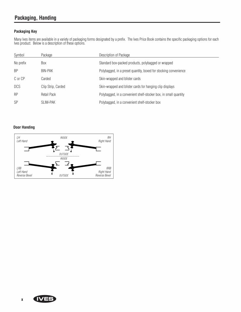
Packaging Key
Many Ives items are available in a variety of packaging forms designated by a prefix. The Ives Price Book contains the specific packaging options for eachIves product. Below is a description of these options.
Symbol Package Description of Package
No prefix Box Standard box-packed products, polybagged or wrapped
BP BIN-PAK Polybagged, in a preset quantity, boxed for stocking convenience
C or CP Carded Skin-wrapped and blister cards
DCS Clip Strip, Carded Skin-wrapped and blister cards for hanging clip displays
RP Retail Pack Polybagged, in a convenient shelf-stocker box, in small quantity
SP SLIM-PAK Polybagged, in a convenient shelf-stocker box
Door Handing
LH INSIDE RHLeft Hand Right Hand
LRB RRB Left Hand Right HandReverse Bevel OUTSIDE Reverse Bevel
OUTSIDE
INSIDE
xi
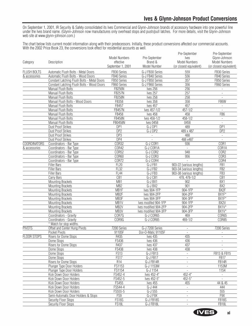
Ives & Glynn-Johnson Product ConversionsOn September 1, 2001, IR Security & Safety consolidated its Ives Commercial and Glynn-Johnson brands of accessory hardware into one powerful lineunder the Ives brand name. (Glynn-Johnson now manufactures only overhead stops and push/pull latches. For more details, visit the Glynn-Johnsonweb site at www.glynn-johnson.com.)
The chart below lists current model information along with their predecessors. Initially, these product conversions affected our commercial accounts.With the 2002 Price Book 23, the conversions took effect for residential accounts as well.
Pre-September Pre-SeptemberModel Numbers Pre-September Ives Glynn-Johnson
Category Description effective Brand & Model Numbers Model NumbersSeptember 1, 2001 Model Number (or closest equivalent) (or closest equivalent)
FLUSH BOLTS Automatic Flush Bolts - Metal Doors FB30 Series G-J FB30 Series 559 FB30 Series& accessories Automatic Flush Bolts - Wood Doors FB40 Series G-J FB40 Series 556 FB40 Series
Constant Latching Flush Bolts - Metal Doors FB50 Series G-J FB50 Series 357 FB50 SeriesConstant Latching Flush Bolts - Wood Doors FB60 Series G-J FB60 Series 356 FB60 SeriesManual Flush Bolts FB256N Ives 256 256 -Manual Flush Bolts FB257N Ives 257 257 -Manual Flush Bolts FB258N Ives 258 258 -Manual Flush Bolts - Wood Doors FB358 Ives 358 358 FB6WManual Flush Bolts FB457 Ives 457 457 -Manual Flush Bolts FB457N Ives 457-1/2 457-1/2 -Manual Flush Bolts FB458 Ives 458 458 FB6Manual Flush Bolts FB458N Ives 458-1/2 458-1/2 -Manual Flush Bolts FB0458N Ives 0458 0458 -Dust Proof Strikes DP1 G-J DP1 489 DP1Dust Proof Strikes DP2 G-J DP2 489 x 487 DP2Dust Proof Strikes DP3 - 488 -Dust Proof Strikes DP4 - 488 x487 -
COORDINATORS Coordinators - Bar Type COR32 G-J COR1 936 COR1& accessories Coordinators - Bar Type COR42 G-J COR1A - COR1A
Coordinators - Bar Type COR52 G-J COR2 948 COR2Coordinators - Bar Type COR60 G-J COR3 956 COR3Coordinators - Bar Type COR72 G-J COR4 - COR4Filler Bars FL20 G-J FB1 903-22 (various lengths) FB1Filler Bars FL32 G-J FB2 903-34 (various lengths) FB2Filler Bars FL44 G-J FB3 903-38 (various lengths) FB3Carry Bars CB1 G-J CB1 478, 478-1/2 CB1Mounting Brackets MB1 G-J BX1 902 BX1Mounting Brackets MB2 G-J BX2 901 BX2Mounting Brackets MB1F Ives 904-1FP 904-1FP BX2FMounting Brackets MB2F Ives 904-2FP 904-2FP BX1F*Mounting Brackets MB3F Ives 904-3FP 904-3FP BX1F*Mounting Brackets MB1V Ives modifed 904-1FP 904-1FP BX2VMounting Brackets MB2V Ives modified 904-2FP 904-2FP BX1V*Mounting Brackets MB3V Ives modified 904-3FP 904-3FP BX1V*Coordinators - Gravity COR7G G-J COR65 469 COR65Coordinators - Gravity COR9G G-J COR85 469-1/2 COR85* Watch for stop widths.
PIVOTS Offset and Center Hung Pivots 7200 Series G-J 7200 Series - 7200 SeriesPocket Pivots 91105F Dor-O-Matic 91105F - -
FLOOR STOPS Risers for Dome Stops R435 Ives 435 435 -Dome Stops FS436 Ives 436 436 -Risers for Dome Stops R437 Ives 437 437 -Dome Stops FS438 Ives 438 438 -Dome Stops FS13 G-J FB13 - FB13 & FB15Dome Stops FS17 G-J FB17 - FB17Risers for Dome Stops R14 G-J FB14R - FB14RPlunger Type Door Holders FS1153 G-J 1153M - 1153MPlunger Type Door Holders FS1154 G-J 1154 - 1154Kick Down Door Holders FS452-4 Ives 452-4" 452-4" -Kick Down Door Holders FS452-5 Ives 452-5" 452-5" -Kick Down Door Holders FS455 Ives 455 455 44 & 45Kick Down Door Holders FS544-4 G-J 444 - 444Kick Down Door Holders FS555-5 G-J 555 - 555Semi-Automatic Door Holders & Stops FS9 G-J F9X - F9XSecurity Floor Stops FS18S G-J FB18S - FB18SSecurity Floor Stops FS18L G-J FB18L - FB18L

xii
Pre-September Pre-SeptemberModel Numbers Pre-September Ives Glynn-Johnson
Category Description effective Brand & Model Numbers Model NumbersSeptember 1, 2001 Model Number (or closest equivalent) (or closest equivalent)
FLOOR STOPS Lock Guards LG14 G-J XLP12 - XLP12Floor Stops FS434 Ives 434 434 -Floor Door Stops FS441 Ives 441 441 -Floor Door Stops FS441-WS Ives 441-WS 441-WS -Floor Door Stops FS442 Ives 442 442 FB19XFloor Door Stops FS442-WS Ives 442-WS 442-WS FB19Heavy Duty Door Stops FS444 Ives 444 444 FB36Heavy Duty Door Stops & Holders FS446 Ives 446 446 F-26Heavy Duty Door Stops FS448 Ives 448 448 -Heavy Duty Door Stops & Holders FS450 Ives 450 450 -Door Stop & Holders FS451 Ives 451 451 F20XDoor Stop & Holders FS451-WS Ives 451-WS 451-WS F20Automatic Door Stops & Holders FS495 Ives 495 495 -Automatic Door Stops & Holders FS496 Ives 496 496 -Automatic Door Stops & Holders FS40 G-J F40A - F40AAutomatic Door Stops & Holders FS41 G-J F41A - F41AAutomatic Door Stops & Holders FS42 G-J F42A - F42AAutomatic Door Stops & Holders FS43 G-J F43A - F43AStrikes for FS40 Series STK40 G-J F40 - F40Strikes for FS40 Series STK41 G-J F41 - F41Strikes for FS40 Series STK42 G-J F42 - F42Strikes for FS40 Series STK43 G-J F43 - F43
WALL STOPS Wall Stops WS11 G-J WB11 - WB11Wall Stops WS11X G-J WB11X - WB11XWall Stop Holders & Strikes WS20 G-J W20 - W20Wall Stops WS20X G-J W20X - W20XWall Stops WS33 G-J WB33 - WB33Wall Stops WS33X G-J WB33X - WB33XAutomatic Holders & Stops WS40 G-J W40 - W40Automatic Holders & Stops WS45 G-J W-45A - W-45AAutomatic Holders & Stops WS45X G-J W-45AX - W-45AXBase Door Stops WS65 Ives 65 65 -Heavy Duty Wall Stops & Holders WS443 Ives 443 443 -Heavy Duty Wall Stops & Holders WS445 Ives 445 445 W-27Heavy Duty Wall Stops & Holders WS447 Ives 447 447 WB35Heavy Duty Wall Stops & Holders WS449 Ives 449 449 -Wall Bumpers WS401CVX Ives 401 401 50C-Wood ScrewsWall Bumpers WS401CCV Ives 401-1/2 401-1/2 60C-Wood ScrewsWall Bumpers WS402CVX Ives 402 402 50CWall Bumpers WS402CCV Ives 402-1/2 402-1/2 60CWall Bumpers WS404CVX Ives 404 404 25CWall Bumpers WS406CVX Ives 406 406 50W-Wood ScrewsWall Bumpers WS406CCV Ives 406-1/2 406-1/2 60W-Wood ScrewsWall Bumpers WS407CVX Ives 407 407 50WWall Bumpers WS407CCV Ives 407-1/2 407-1/2 60W
SILENCERS Silencers SR64 GJ 64 20R 64Silencers SR65 GJ 65 21R 65Silencers SR66 GJ 66 - 66
ROLLER BUMPERS Roller Bumpers RB470 Ives 470 470 RB3Roller Bumpers RB471 Ives 471 471 RB4Roller Bumpers RB472 Ives 472 472 RB6
Ives & Glynn-Johnson Product Conversions
Pre-September Pre-SeptemberModel Numbers Pre-September Ives Glynn-Johnson
Category Description effective Brand & Model Numbers Model NumbersSeptember 1, 2001 Model Number (or closest equivalent) (or closest equivalent)
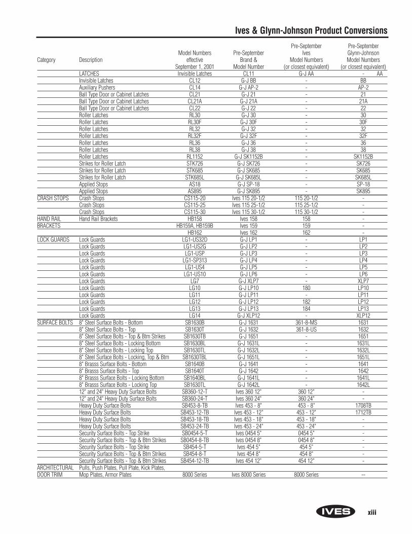
LATCHES Invisible Latches CL11 G-J AA - AAInvisible Latches CL12 G-J BB - BBAuxiliary Pushers CL14 G-J AP-2 - AP-2Ball Type Door or Cabinet Latches CL21 G-J 21 - 21Ball Type Door or Cabinet Latches CL21A G-J 21A - 21ABall Type Door or Cabinet Latches CL22 G-J 22 - 22Roller Latches RL30 G-J 30 - 30Roller Latches RL30F G-J 30F - 30FRoller Latches RL32 G-J 32 - 32Roller Latches RL32F G-J 32F - 32FRoller Latches RL36 G-J 36 - 36Roller Latches RL38 G-J 38 - 38Roller Latches RL1152 G-J SK1152B - SK1152BStrikes for Roller Latch STK726 G-J SK726 - SK726Strikes for Roller Latch STK685 G-J SK685 - SK685Strikes for Roller Latch STK685L G-J SK685L - SK685LApplied Stops AS18 G-J SP-18 - SP-18Applied Stops AS895 G-J SK895 - SK895
CRASH STOPS Crash Stops CS115-20 Ives 115 20-1/2 115 20-1/2 -Crash Stops CS115-25 Ives 115 25-1/2 115 25-1/2 -Crash Stops CS115-30 Ives 115 30-1/2 115 30-1/2 -
HAND RAIL Hand Rail Brackets HB158 Ives 158 158 -BRACKETS HB159A, HB159B Ives 159 159 -
HB162 Ives 162 162 -LOCK GUARDS Lock Guards LG1-US32D G-J LP1 - LP1
Lock Guards LG1-US2G G-J LP2 - LP2Lock Guards LG1-USP G-J LP3 - LP3Lock Guards LG1-SP313 G-J LP4 - LP4Lock Guards LG1-US4 G-J LP5 - LP5Lock Guards LG1-US10 G-J LP6 - LP6Lock Guards LG7 G-J XLP7 - XLP7Lock Guards LG10 G-J LP10 180 LP10Lock Guards LG11 G-J LP11 - LP11Lock Guards LG12 G-J LP12 182 LP12Lock Guards LG13 G-J LP13 184 LP13Lock Guards LG14 G-J XLP12 - XLP12
SURFACE BOLTS 8" Steel Surface Bolts - Bottom SB1630B G-J 1631 361-8-MS 16318" Steel Surface Bolts - Top SB1630T G-J 1632 361-8-US 16328" Steel Surface Bolts - Top & Btm Strikes SB1630TB G-J 1651 - 16518" Steel Surface Bolts - Locking Bottom SB1630BL G-J 1631L - 1631L8" Steel Surface Bolts - Locking Top SB1630TL G-J 1632L - 1632L8" Steel Surface Bolts - Locking, Top & Btm SB1630TBL G-J 1651L - 1651L8" Brasss Surface Bolts - Bottom SB1640B G-J 1641 - 16418" Brasss Surface Bolts - Top SB1640T G-J 1642 - 16428" Brasss Surface Bolts - Locking Bottom SB1640BL G-J 1641L - 1641L8" Brasss Surface Bolts - Locking Top SB1630TL G-J 1642L - 1642L12" and 24" Heavy Duty Surface Bolts SB360-12-T Ives 360 12" 360 12" -12" and 24" Heavy Duty Surface Bolts SB360-24-T Ives 360 24" 360 24" -Heavy Duty Surface Bolts SB453-8-TB Ives 453 - 8" 453 - 8" 1708TBHeavy Duty Surface Bolts SB453-12-TB Ives 453 - 12" 453 - 12" 1712TBHeavy Duty Surface Bolts SB453-18-TB Ives 453 - 18" 453 - 18" -Heavy Duty Surface Bolts SB453-24-TB Ives 453 - 24" 453 - 24" -Security Surface Bolts - Top Strike SB0454-5-T Ives 0454 5" 0454 5" -Security Surface Bolts - Top & Btm Strikes SB0454-8-TB Ives 0454 8" 0454 8" -Security Surface Bolts - Top Strike SB454-5-T Ives 454 5" 454 5" -Security Surface Bolts - Top & Btm Strikes SB454-8-T Ives 454 8" 454 8" -Security Surface Bolts - Top & Btm Strikes SB454-12-TB Ives 454 12" 454 12" -
ARCHITECTURAL Pulls, Push Plates, Pull Plate, Kick Plates,DOOR TRIM Mop Plates, Armor Plates 8000 Series Ives 8000 Series 8000 Series --
xiii
Ives & Glynn-Johnson Product Conversions

xiv
Notes
xv
Ives & Glynn-Johnson Product Conversions
xvi
Notes
Section AFlush Bolts andCoordinators
A1
Automatic Flush Bolts - Metal Doors
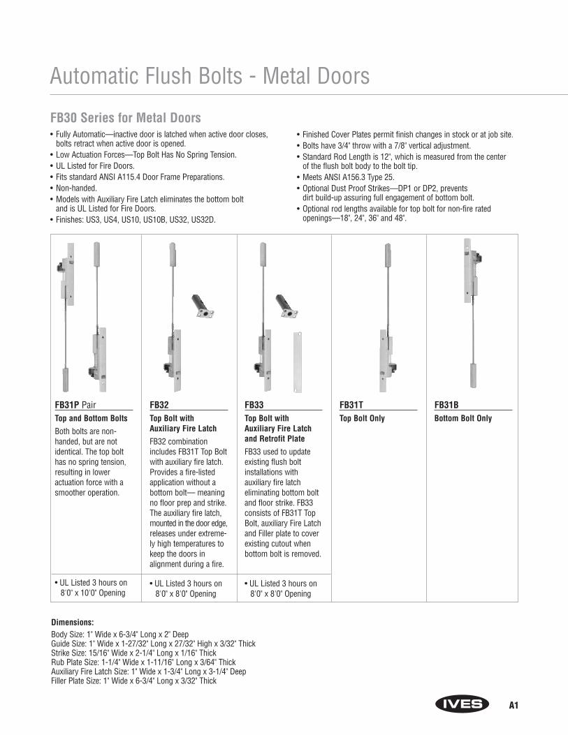
FB30 Series for Metal Doors• Fully Automatic—inactive door is latched when active door closes,
bolts retract when active door is opened.• Low Actuation Forces—Top Bolt Has No Spring Tension.• UL Listed for Fire Doors.• Fits standard ANSI A115.4 Door Frame Preparations.• Non-handed.• Models with Auxiliary Fire Latch eliminates the bottom bolt
and is UL Listed for Fire Doors.• Finishes: US3, US4, US10, US10B, US32, US32D.
• Finished Cover Plates permit finish changes in stock or at job site.• Bolts have 3/4" throw with a 7/8" vertical adjustment.• Standard Rod Length is 12", which is measured from the center
of the flush bolt body to the bolt tip. • Meets ANSI A156.3 Type 25.• Optional Dust Proof Strikes—DP1 or DP2, prevents
dirt build-up assuring full engagement of bottom bolt.• Optional rod lengths available for top bolt for non-fire rated
openings—18", 24", 36" and 48".
FB31P PairTop and Bottom Bolts
Both bolts are non-handed, but are notidentical. The top bolthas no spring tension,resulting in lower actuation force with asmoother operation.
• UL Listed 3 hours on8'0" x 10'0" Opening
FB32Top Bolt with Auxiliary Fire Latch
FB32 combinationincludes FB31T Top Boltwith auxiliary fire latch.Provides a fire-listedapplication without abottom bolt— meaningno floor prep and strike.The auxiliary fire latch,mounted in the door edge,releases under extreme-ly high temperatures tokeep the doors in alignment during a fire.
• UL Listed 3 hours on8'0" x 8'0" Opening
FB33Top Bolt with Auxiliary Fire Latch and Retrofit Plate
FB33 used to updateexisting flush boltinstallations with auxiliary fire latch eliminating bottom boltand floor strike. FB33consists of FB31T TopBolt, auxiliary Fire Latchand Filler plate to coverexisting cutout whenbottom bolt is removed.
• UL Listed 3 hours on8'0" x 8'0" Opening
FB31TTop Bolt Only
FB31BBottom Bolt Only
Dimensions:Body Size: 1" Wide x 6-3/4" Long x 2" DeepGuide Size: 1" Wide x 1-27/32" Long x 27/32" High x 3/32" ThickStrike Size: 15/16" Wide x 2-1/4" Long x 1/16" ThickRub Plate Size: 1-1/4" Wide x 1-11/16" Long x 3/64" Thick Auxiliary Fire Latch Size: 1" Wide x 1-3/4" Long x 3-1/4" DeepFiller Plate Size: 1" Wide x 6-3/4" Long x 3/32" Thick
A2
Automatic Flush Bolts - Wood Doors
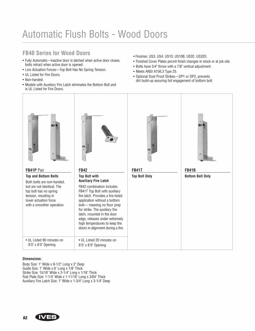
FB40 Series for Wood Doors• Fully Automatic—inactive door is latched when active door closes,
bolts retract when active door is opened.• Low Actuation Forces—Top Bolt Has No Spring Tension.• UL Listed for Fire Doors.• Non-handed.• Models with Auxiliary Fire Latch eliminates the Bottom Bolt and
is UL Listed for Fire Doors.
• Finishes: US3, US4, US10, US10B, US32, US32D.• Finished Cover Plates permit finish changes in stock or at job site.• Bolts have 3/4" throw with a 7/8" vertical adjustment.• Meets ANSI A156.3 Type 25.• Optional Dust Proof Strikes—DP1 or DP2, prevents
dirt build-up assuring full engagement of bottom bolt.
FB41P PairTop and Bottom Bolts
Both bolts are non-handed, but are not identical. The top bolt has no spring tension, resulting in lower actuation forcewith a smoother operation.
• UL Listed 90 minutes on 8'0" x 8'0" Opening
FB42Top Bolt with Auxiliary Fire Latch
FB42 combination includesFB41T Top Bolt with auxiliaryfire latch. Provides a fire-listed application without a bottombolt— meaning no floor prepfor strike. The auxiliary firelatch, mounted in the dooredge, releases under extremelyhigh temperatures to keep thedoors in alignment during a fire.
• UL Listed 20 minutes on 8'0" x 8'0" Opening
FB41TTop Bolt Only
FB41BBottom Bolt Only
Dimensions:Body Size: 1" Wide x 8-1/2" Long x 2" DeepGuide Size: 1" Wide x 6" Long x 1/8" ThickStrike Size: 15/16" Wide x 2-1/4" Long x 1/16" ThickRub Plate Size: 1-1/4" Wide x 1-11/16" Long x 3/64" ThickAuxiliary Fire Latch Size: 1" Wide x 1-3/4" Long x 3-1/4" Deep
A3
Constant Latching Flush Bolts - Metal Doors
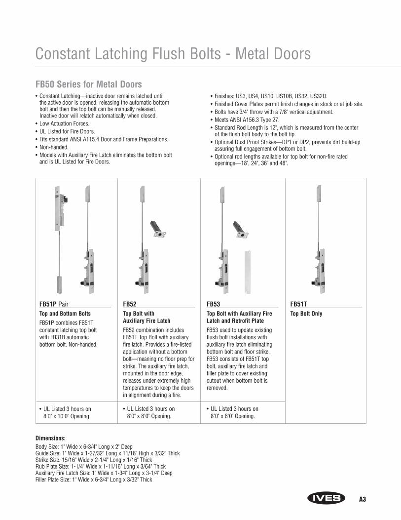
FB50 Series for Metal Doors• Constant Latching—inactive door remains latched until
the active door is opened, releasing the automatic bottom bolt and then the top bolt can be manually released. Inactive door will relatch automatically when closed.
• Low Actuation Forces.• UL Listed for Fire Doors.• Fits standard ANSI A115.4 Door and Frame Preparations.• Non-handed.• Models with Auxiliary Fire Latch eliminates the bottom bolt
and is UL Listed for Fire Doors.
• Finishes: US3, US4, US10, US10B, US32, US32D.• Finished Cover Plates permit finish changes in stock or at job site.• Bolts have 3/4" throw with a 7/8" vertical adjustment.• Meets ANSI A156.3 Type 27.• Standard Rod Length is 12", which is measured from the center
of the flush bolt body to the bolt tip. • Optional Dust Proof Strikes—DP1 or DP2, prevents dirt build-up
assuring full engagement of bottom bolt.• Optional rod lengths available for top bolt for non-fire rated
openings—18", 24", 36" and 48".
FB51P PairTop and Bottom Bolts
FB51P combines FB51T constant latching top bolt with FB31B automatic bottom bolt. Non-handed.
• UL Listed 3 hours on 8'0" x 10'0" Opening.
FB52Top Bolt with Auxiliary Fire Latch
FB52 combination includesFB51T Top Bolt with auxiliaryfire latch. Provides a fire-listedapplication without a bottombolt—meaning no floor prep forstrike. The auxiliary fire latch,mounted in the door edge,releases under extremely hightemperatures to keep the doorsin alignment during a fire.
• UL Listed 3 hours on 8'0" x 8'0" Opening.
FB53Top Bolt with Auxiliary FireLatch and Retrofit Plate
FB53 used to update existingflush bolt installations with auxiliary fire latch eliminatingbottom bolt and floor strike.FB53 consists of FB51T topbolt, auxiliary fire latch andfiller plate to cover existingcutout when bottom bolt isremoved.
• UL Listed 3 hours on 8'0" x 8'0" Opening.
FB51TTop Bolt Only
Dimensions:Body Size: 1" Wide x 6-3/4" Long x 2" DeepGuide Size: 1" Wide x 1-27/32" Long x 11/16" High x 3/32" ThickStrike Size: 15/16" Wide x 2-1/4" Long x 1/16" ThickRub Plate Size: 1-1/4" Wide x 1-11/16" Long x 3/64" ThickAuxiliary Fire Latch Size: 1" Wide x 1-3⁄4" Long x 3-1/4" DeepFiller Plate Size: 1" Wide x 6-3/4" Long x 3/32" Thick

A4
Constant Latching Flush Bolts - Wood Doors
FB60 Series for Wood Doors• Constant Latching—inactive door remains latched until the
active door is opened, releasing the automatic bottom bolt andthen the top bolt can be manually released. Inactive door willrelatch automatically when door closes.
• Low Actuation Forces.• UL Listed for Fire Doors.• Non-handed.
• Models with Auxiliary Fire Latch eliminates the bottom bolt and is UL Listed for Fire Doors.
• Finishes: US3, US4, US10, US10B, US32, US32D.• Finished Cover Plates permit finish changes in stock or at job site.• Bolts have 3/4" throw with a 7/8" vertical adjustment.• Meets ANSI A156.3 Type 27.• Optional Dust Proof Strikes—DP1 or DP2, prevents
dirt build-up assuring full engagement of bottom bolt.
FB61P PairTop and Bottom Bolts
FB61P combines FB61T constant latching top bolt with FB41B bottom bolt.
• UL Listed 90 minutes on 8'0" x 8'0" Opening
FB62Top Bolt with Auxiliary Fire Latch
FB62 combination includes FB61T top boltwith Auxiliary Fire Latch. Provides a fire-listed application without a bottombolt—meaning no floor prep for strike. The Auxiliary Fire Latch, mounted in thedoor edge, releases under extremely high temperatures to keep the doors in alignment during a fire.
• UL Listed 20 minutes on 8'0" x 8'0" Opening
FB61TTop Bolt Only
Dimensions:Body Size: 1" Wide x 8-1/2" Long x 2" DeepGuide Size: 1" Wide x 6" Long x 1/8" ThickStrike Size: 15/16" Wide x 2-1/4" Long x 1/16" ThickRub Plate Size: 1-1/4" Wide x 1-11/16" Long x 3/64" ThickAuxiliary Fire Latch Size: 1" Wide x 1-3/4" Long x 3-1/4" Deep
A5
Manual Flush Bolts - Metal Doors
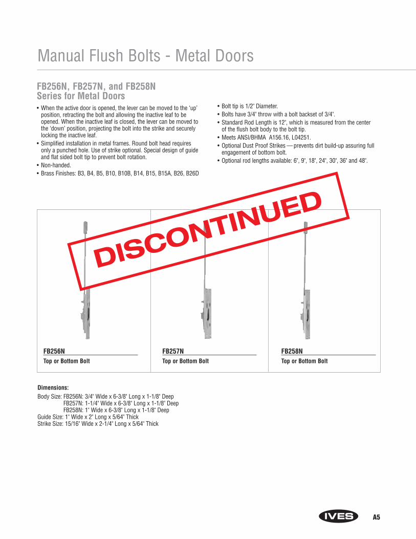
FB256N, FB257N, and FB258NSeries for Metal Doors• When the active door is opened, the lever can be moved to the ‘up’
position, retracting the bolt and allowing the inactive leaf to beopened. When the inactive leaf is closed, the lever can be moved tothe ‘down’ position, projecting the bolt into the strike and securelylocking the inactive leaf.
• Simplified installation in metal frames. Round bolt head requiresonly a punched hole. Use of strike optional. Special design of guideand flat sided bolt tip to prevent bolt rotation.
• Non-handed.• Brass Finishes: B3, B4, B5, B10, B10B, B14, B15, B15A, B26, B26D
• Bolt tip is 1/2" Diameter.• Bolts have 3/4" throw with a bolt backset of 3/4".• Standard Rod Length is 12", which is measured from the center
of the flush bolt body to the bolt tip. • Meets ANSI/BHMA A156.16, L04251.• Optional Dust Proof Strikes — prevents dirt build-up assuring full
engagement of bottom bolt.• Optional rod lengths available: 6", 9", 18", 24", 30", 36" and 48".
FB256NTop or Bottom Bolt
FB257NTop or Bottom Bolt
FB258NTop or Bottom Bolt
Dimensions:Body Size: FB256N: 3/4" Wide x 6-3/8" Long x 1-1/8" Deep
FB257N: 1-1/4" Wide x 6-3/8" Long x 1-1/8" DeepFB258N: 1" Wide x 6-3/8" Long x 1-1/8" Deep
Guide Size: 1" Wide x 2" Long x 5/64" ThickStrike Size: 15/16" Wide x 2-1/4" Long x 5/64" Thick
DISCONTINUED
A6
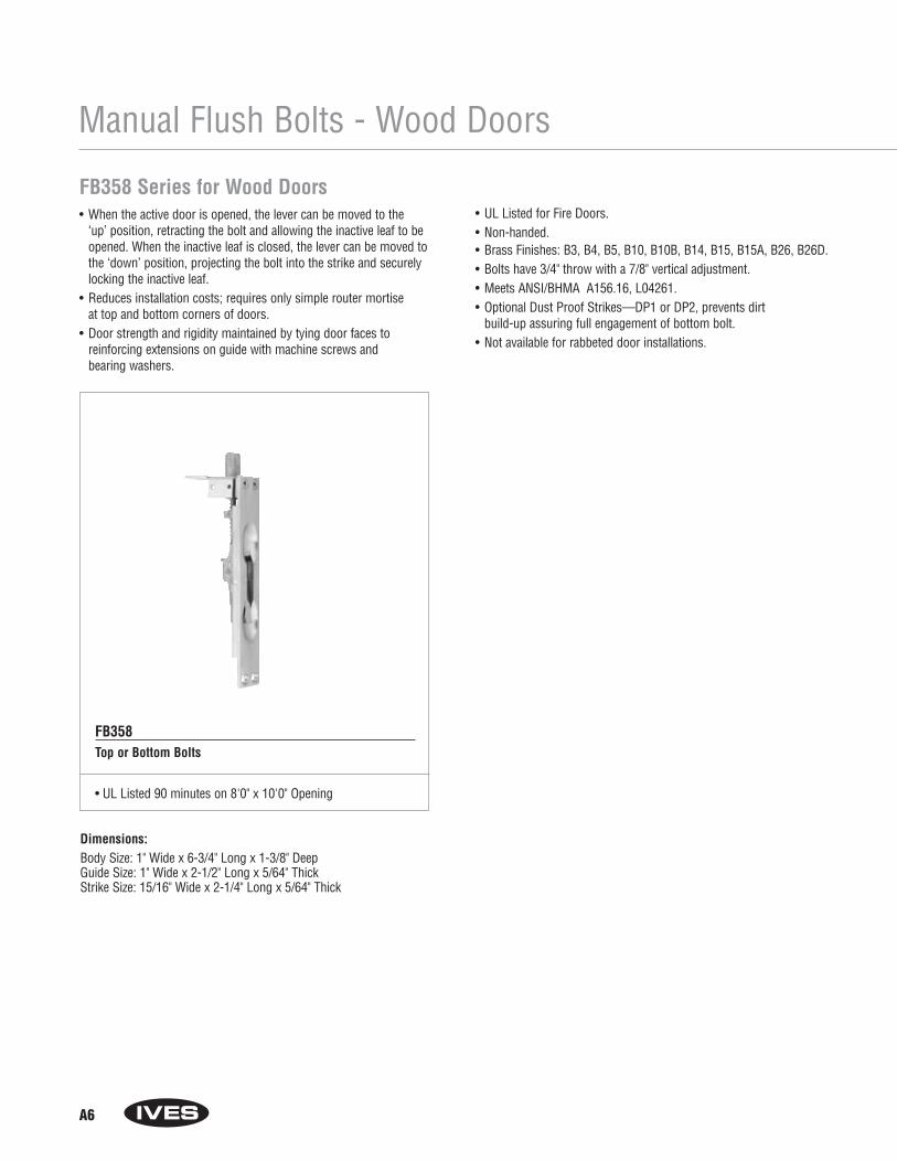
FB358 Series for Wood Doors• When the active door is opened, the lever can be moved to the
‘up’ position, retracting the bolt and allowing the inactive leaf to beopened. When the inactive leaf is closed, the lever can be moved tothe ‘down’ position, projecting the bolt into the strike and securelylocking the inactive leaf.
• Reduces installation costs; requires only simple router mortise at top and bottom corners of doors.
• Door strength and rigidity maintained by tying door faces to reinforcing extensions on guide with machine screws and bearing washers.
• UL Listed for Fire Doors.• Non-handed.• Brass Finishes: B3, B4, B5, B10, B10B, B14, B15, B15A, B26, B26D.• Bolts have 3/4" throw with a 7/8" vertical adjustment.• Meets ANSI/BHMA A156.16, L04261.• Optional Dust Proof Strikes—DP1 or DP2, prevents dirt
build-up assuring full engagement of bottom bolt.• Not available for rabbeted door installations.
FB358Top or Bottom Bolts
• UL Listed 90 minutes on 8'0" x 10'0" Opening
Manual Flush Bolts - Wood Doors
Dimensions:Body Size: 1" Wide x 6-3/4" Long x 1-3/8" DeepGuide Size: 1" Wide x 2-1/2" Long x 5/64" ThickStrike Size: 15/16" Wide x 2-1/4" Long x 5/64" Thick
A7
Manual Flush Bolts - Metal Doors
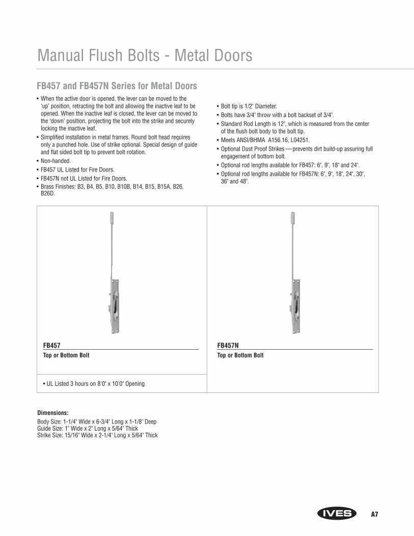
FB457 and FB457N Series for Metal Doors• When the active door is opened, the lever can be moved to the
‘up’ position, retracting the bolt and allowing the inactive leaf to beopened. When the inactive leaf is closed, the lever can be moved tothe ‘down’ position, projecting the bolt into the strike and securelylocking the inactive leaf.
• Simplified installation in metal frames. Round bolt head requiresonly a punched hole. Use of strike optional. Special design of guideand flat sided bolt tip to prevent bolt rotation.
• Non-handed.• FB457 UL Listed for Fire Doors.• FB457N not UL Listed for Fire Doors.• Brass Finishes: B3, B4, B5, B10, B10B, B14, B15, B15A, B26,
B26D.
• Bolt tip is 1/2" Diameter.• Bolts have 3/4" throw with a bolt backset of 3/4".• Standard Rod Length is 12", which is measured from the center
of the flush bolt body to the bolt tip. • Meets ANSI/BHMA A156.16, L04251.• Optional Dust Proof Strikes — prevents dirt build-up assuring full
engagement of bottom bolt.• Optional rod lengths available for FB457: 6", 9", 18" and 24".• Optional rod lengths available for FB457N: 6", 9", 18", 24", 30",
36" and 48".
FB457Top or Bottom Bolt
• UL Listed 3 hours on 8'0" x 10'0" Opening
FB457NTop or Bottom Bolt
Dimensions:Body Size: 1-1/4" Wide x 6-3/4" Long x 1-1/8" DeepGuide Size: 1" Wide x 2" Long x 5/64" ThickStrike Size: 15/16" Wide x 2-1/4" Long x 5/64" Thick
A8
Manual Flush Bolts - Metal Doors
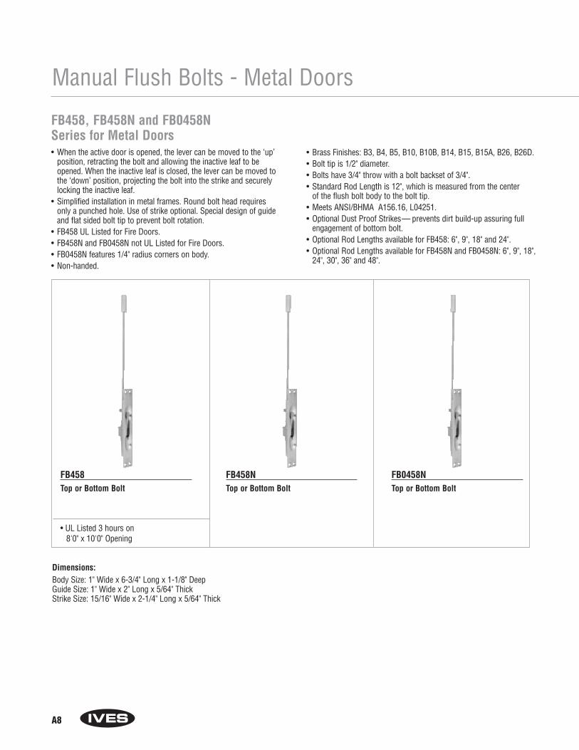
FB458, FB458N and FB0458N Series for Metal Doors• When the active door is opened, the lever can be moved to the ‘up’
position, retracting the bolt and allowing the inactive leaf to beopened. When the inactive leaf is closed, the lever can be moved tothe ‘down’ position, projecting the bolt into the strike and securelylocking the inactive leaf.
• Simplified installation in metal frames. Round bolt head requiresonly a punched hole. Use of strike optional. Special design of guideand flat sided bolt tip to prevent bolt rotation.
• FB458 UL Listed for Fire Doors.• FB458N and FB0458N not UL Listed for Fire Doors.• FB0458N features 1/4" radius corners on body.• Non-handed.
• Brass Finishes: B3, B4, B5, B10, B10B, B14, B15, B15A, B26, B26D.• Bolt tip is 1/2" diameter.• Bolts have 3/4" throw with a bolt backset of 3/4".• Standard Rod Length is 12", which is measured from the center
of the flush bolt body to the bolt tip. • Meets ANSI/BHMA A156.16, L04251.• Optional Dust Proof Strikes— prevents dirt build-up assuring full
engagement of bottom bolt.• Optional Rod Lengths available for FB458: 6", 9", 18" and 24".• Optional Rod Lengths available for FB458N and FB0458N: 6", 9", 18",
24", 30", 36" and 48".
FB458Top or Bottom Bolt
• UL Listed 3 hours on 8'0" x 10'0" Opening
FB458NTop or Bottom Bolt
FB0458NTop or Bottom Bolt
Dimensions:Body Size: 1" Wide x 6-3/4" Long x 1-1/8" DeepGuide Size: 1" Wide x 2" Long x 5/64" ThickStrike Size: 15/16" Wide x 2-1/4" Long x 5/64" Thick
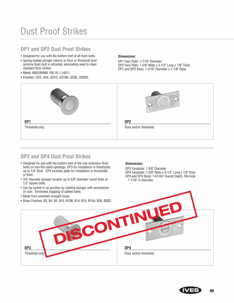
A9
Dust Proof Strikes
DP1 and DP2 Dust Proof Strikes• Designed for use with the bottom bolt of all flush bolts. • Spring-loaded plunger returns to floor or threshold level
anytime flush bolt is retracted, eliminating need to clean standard floor strikes.
• Meets ANSI/BHMA 156.16, L14011.• Finishes: US3, US4, US10, US10B, US26, US26D.
Dimensions:DP1 Face Plate: 1-7/16" DiameterDP2 Face Plate: 1-5/8" Wide x 3-1/2" Long x 1/8" ThickDP1 and DP2 Body: 1-3/16" Diameter x 1-7/8" Deep
DP1Threshold only.
DP2Floor and/or threshold.
DP3 and DP4 Dust Proof Strikes• Designed for use with the bottom bolt of the Ives extension flush
bolts on non-fire rated openings. DP3 for installation in thresholdsup to 1/4" thick. DP4 includes plate for installation in thresholds or floor.
• 3/4" diameter plunger accepts up to 5/8" diameter round bolts or1/2" square bolts.
• Can be locked in up position by rotating plunger with screwdriver or coin. Eliminates trapping of spiked heels.
• Made from polished wrought brass.• Brass Finishes: B3, B4, B5, B10, B10B, B14, B15, B15A, B26, B26D.
Dimensions:DP3 Faceplate: 1-3/8" DiameterDP4 Faceplate: 1-5/8" Wide x 3-1/2" Long x 1/8" thickDP3 and DP4 Body: 1-61/64" Overall Depth, Fits Hole
1-1/16" in Diameter
DP3Threshold only.
DP4Floor and/or threshold.
DISCONTINUED

A10
Manual Flush Bolts
260 Series• Designed with face plate rounded for simple, one-step router
installation.• Steel bolt head in nylon bushing combined with dual action spring
lock to hold bolt projected or retracted provides easy, one-fingeroperation.
• Economically priced for the volume builder.• Made from polished wrought brass.• Finishes: B3, B4, B5, B10, B10B, B14, B15, B15A, B19, B26, B26D.
Dimensions:Body Size: 3/4" Wide x 6-3/4" Long x 5/8" DeepStrike Size: 5/8" Wide x 1-1/2" LongRod Backset: 3/8"Diameter of Bolt Head: 5/16"Throw: 3/4"
261 Series• An exceptionally smooth working flush bolt with sharp, crisp lines.• Double action spring design provides automatic holding of brass
bolt in projected or retracted position, and assures ease of operation in conjunction with deep cup finger hole.
• Made from polished cast brass.• Finishes: B3, B4, B5, B10, B10B, B14, B15, B15A, B19, B26, B26D.
Dimensions:Body Size: 3/4" Wide x 4" Long x 1-1/8" DeepStrike Size: 5/8" Wide x 1-1/2" LongRod Backset: 15/32"Diameter of Bolt Head: 5/16"Throw: 3/4"
Dimensions:Body Size: 3/4" Wide x 6" Long x 1-11/32" DeepStrike Size: 7/8" Wide x 1-3/4" LongRod Backset: 15/32"Diameter of Bolt Head: 1/2"Throw: 1"
Dimensions:Body Size: 3/4" Wide x 5" Long x 1-1/2" DeepStrike Size: 5/8" Wide x 1-1/2" LongRod Backset: 15/32"Diameter of Bolt Head: 5/16"Throw: 3/4"
262 Series• An exceptionally smooth working flush bolt with sharp, crisp lines.• Double action spring design provides automatic holding of brass
bolt in projected or retracted position, and assures ease of operation in conjunction with deep cup finger hole.
• Made from polished cast brass.• Finishes: B3, B4, B5, B10, B10B, B14, B15, B15A, B19, B26, B26D.
263 Series• A compact flush bolt designed specifically for easy, low cost
installation.• Rounded faceplate and lip for simplified installation.• Double action spring design provides automatic holding of brass
bolt in projected or retracted position, and assures ease of operation in conjunction with deep cup finger hole.
• Made from polished cast brass.• Finishes: B3, B4, B5, B10, B10B, B14, B15, B15A, B19, B26, B26D.
DISCONTINUED
DISCONTINUED
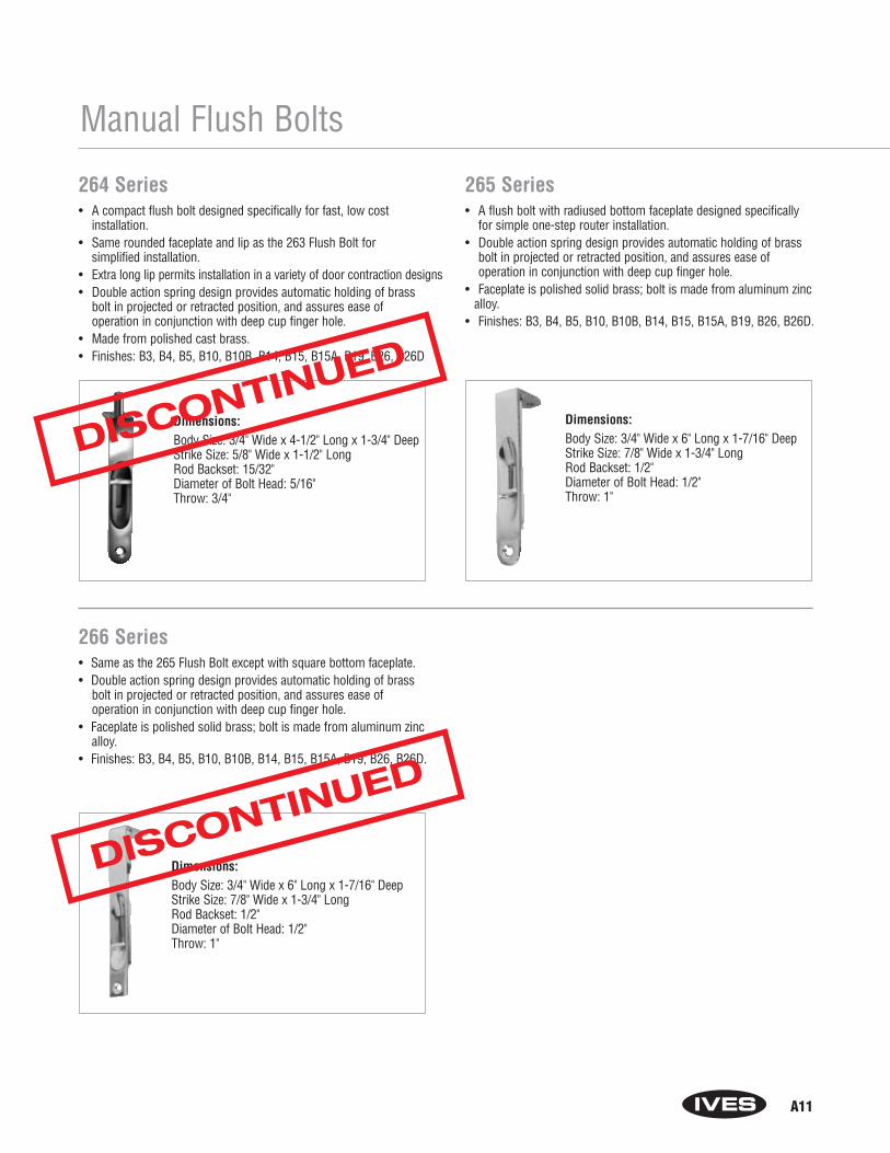
A11
Manual Flush Bolts
264 Series• A compact flush bolt designed specifically for fast, low cost
installation.• Same rounded faceplate and lip as the 263 Flush Bolt for
simplified installation.• Extra long lip permits installation in a variety of door contraction designs• Double action spring design provides automatic holding of brass
bolt in projected or retracted position, and assures ease of operation in conjunction with deep cup finger hole.
• Made from polished cast brass.• Finishes: B3, B4, B5, B10, B10B, B14, B15, B15A, B19, B26, B26D
265 Series• A flush bolt with radiused bottom faceplate designed specifically
for simple one-step router installation.• Double action spring design provides automatic holding of brass
bolt in projected or retracted position, and assures ease of operation in conjunction with deep cup finger hole.
• Faceplate is polished solid brass; bolt is made from aluminum zinc alloy.
• Finishes: B3, B4, B5, B10, B10B, B14, B15, B15A, B19, B26, B26D.
Dimensions:Body Size: 3/4" Wide x 4-1/2" Long x 1-3/4" DeepStrike Size: 5/8" Wide x 1-1/2" LongRod Backset: 15/32"Diameter of Bolt Head: 5/16"Throw: 3/4"
Dimensions:Body Size: 3/4" Wide x 6" Long x 1-7/16" DeepStrike Size: 7/8" Wide x 1-3/4" LongRod Backset: 1/2"Diameter of Bolt Head: 1/2"Throw: 1"
Dimensions:Body Size: 3/4" Wide x 6" Long x 1-7/16" DeepStrike Size: 7/8" Wide x 1-3/4" LongRod Backset: 1/2"Diameter of Bolt Head: 1/2"Throw: 1"
266 Series• Same as the 265 Flush Bolt except with square bottom faceplate. • Double action spring design provides automatic holding of brass
bolt in projected or retracted position, and assures ease of operation in conjunction with deep cup finger hole.
• Faceplate is polished solid brass; bolt is made from aluminum zinc alloy.
• Finishes: B3, B4, B5, B10, B10B, B14, B15, B15A, B19, B26, B26D.
DISCONTINUED
DISCONTINUED
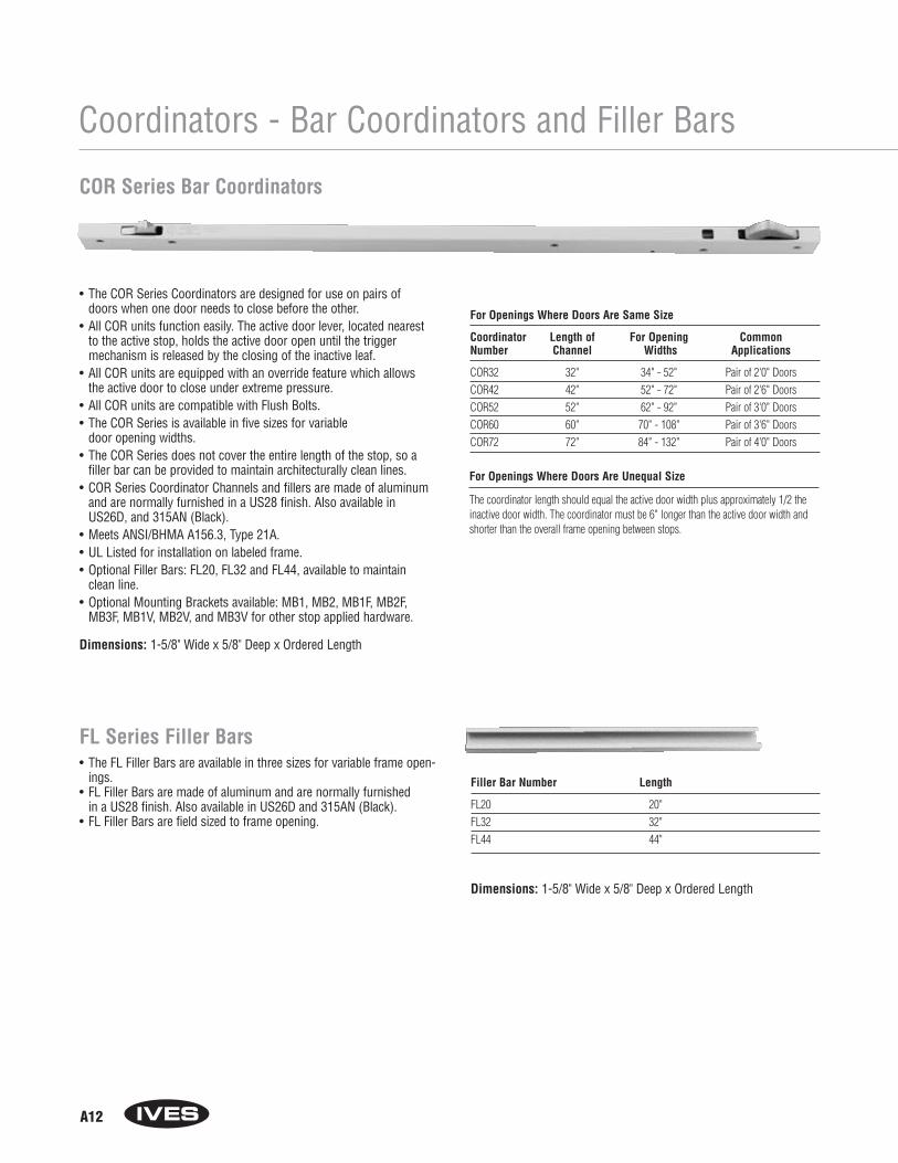
A12
Coordinators - Bar Coordinators and Filler Bars
• The COR Series Coordinators are designed for use on pairs ofdoors when one door needs to close before the other.
• All COR units function easily. The active door lever, located nearestto the active stop, holds the active door open until the triggermechanism is released by the closing of the inactive leaf.
• All COR units are equipped with an override feature which allowsthe active door to close under extreme pressure.
• All COR units are compatible with Flush Bolts. • The COR Series is available in five sizes for variable
door opening widths.• The COR Series does not cover the entire length of the stop, so a
filler bar can be provided to maintain architecturally clean lines. • COR Series Coordinator Channels and fillers are made of aluminum
and are normally furnished in a US28 finish. Also available inUS26D, and 315AN (Black).
• Meets ANSI/BHMA A156.3, Type 21A.• UL Listed for installation on labeled frame.• Optional Filler Bars: FL20, FL32 and FL44, available to maintain
clean line.• Optional Mounting Brackets available: MB1, MB2, MB1F, MB2F,
MB3F, MB1V, MB2V, and MB3V for other stop applied hardware.
COR Series Bar Coordinators
For Openings Where Doors Are Same Size
Coordinator Length of For Opening CommonNumber Channel Widths Applications
COR32 32" 34" - 52" Pair of 2'0" DoorsCOR42 42" 52" - 72" Pair of 2'6" DoorsCOR52 52" 62" - 92" Pair of 3'0" DoorsCOR60 60" 70" - 108" Pair of 3'6" DoorsCOR72 72" 84" - 132" Pair of 4'0" Doors
Filler Bar Number Length
FL20 20"FL32 32"FL44 44"
Dimensions: 1-5/8" Wide x 5/8" Deep x Ordered Length
For Openings Where Doors Are Unequal Size
The coordinator length should equal the active door width plus approximately 1/2 theinactive door width. The coordinator must be 6" longer than the active door width andshorter than the overall frame opening between stops.
FL Series Filler Bars• The FL Filler Bars are available in three sizes for variable frame open-
ings.• FL Filler Bars are made of aluminum and are normally furnished
in a US28 finish. Also available in US26D and 315AN (Black).• FL Filler Bars are field sized to frame opening.
Dimensions: 1-5/8" Wide x 5/8" Deep x Ordered Length

A13
Coordinators - Mounting Brackets
MB1 and MB2• Allows stop mounted hardware to be properly installed without
damaging the COR coordinator, such as a parallel arm closer or a non-fire-rated surface vertical rod strike.
• Stop mounted hardware will need to be lowered to compensate for the height of the coordinator and mounting bracket.
• MB mounting brackets are made of aluminum and normally furnished in a USP finish. Powder Coated Finishes: SP28 andSPBLK.
MB1F, MB2F and MB3F• Allows stop mounted hardware to be properly installed without
damaging the COR coordinator. Example: strike for fire-rated surface vertical rod exit device.
• Stop mounted hardware will need to be lowered to compensate for the height of the coordinator and mounting bracket.
• MBF mounting brackets are made of 3/8" thick steel and normally furnished in a USP finish. Powder Coated Finishes: SP28and SPBLK.
MB1V, MB2V and MB3V (not shown)Same as MB1F, MB2F and MB3F with factory preparation for the Von Duprin 8827-F soffit latch.
Mounting Brackets
MB1 MB2
MB1F MB2F MB3F
Product Jamb Depth Stop Width
MB1 4-3/4" Min. Over 2-1/2"MB2 4-3/4" Min. Up to 2-1/2"
Dimensions: MB1: 4" Wide x 3" Deep x 15/16" TallMB2: 4" Wide x 3-1/4" Deep x 1-5/8" Tall
Product Jamb Depth Stop Width
MB1F 5" Min. 1-1/2" to 2-1/4"MB2F 5-7/8" Min. 2-3/8" to 3-1/4"MB3F 6-7/8" Min. 3-3/8" and Wider
Dimensions: MB1F: 4" Wide x 3" Deep x 1-5/8" TallMB2F: 4" Wide x 4" Deep x 1-5/8" TallMB3F: 4" Wide x 3-1/2" Deep x 1" Tall
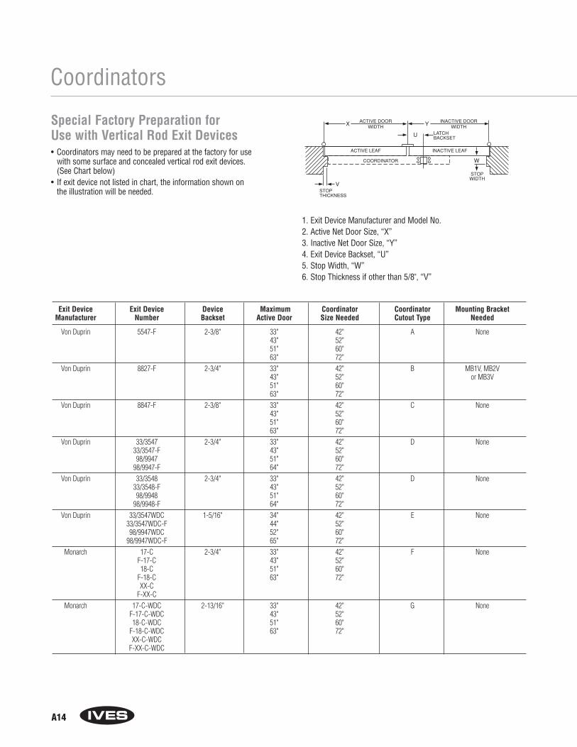
Exit Device Exit Device Device Maximum Coordinator Coordinator Mounting BracketManufacturer Number Backset Active Door Size Needed Cutout Type Needed
Von Duprin 5547-F 2-3/8" 33" 42" A None43" 52"51" 60"63" 72"
Von Duprin 8827-F 2-3/4" 33" 42" B MB1V, MB2V43" 52" or MB3V51" 60"63" 72"
Von Duprin 8847-F 2-3/8" 33" 42" C None43" 52"51" 60"63" 72"
Von Duprin 33/3547 2-3/4" 33" 42" D None33/3547-F 43" 52"98/9947 51" 60"
98/9947-F 64" 72"Von Duprin 33/3548 2-3/4" 33" 42" D None
33/3548-F 43" 52"98/9948 51" 60"
98/9948-F 64" 72"Von Duprin 33/3547WDC 1-5/16" 34" 42" E None
33/3547WDC-F 44" 52"98/9947WDC 52" 60"
98/9947WDC-F 65" 72"Monarch 17-C 2-3/4" 33" 42" F None
F-17-C 43" 52"18-C 51" 60"
F-18-C 63" 72"XX-C
F-XX-CMonarch 17-C-WDC 2-13/16" 33" 42" G None
F-17-C-WDC 43" 52"18-C-WDC 51" 60"
F-18-C-WDC 63" 72"XX-C-WDC
F-XX-C-WDC
A14
Coordinators
Special Factory Preparation for Use with Vertical Rod Exit Devices• Coordinators may need to be prepared at the factory for use
with some surface and concealed vertical rod exit devices. (See Chart below)
• If exit device not listed in chart, the information shown on the illustration will be needed.
1. Exit Device Manufacturer and Model No.2. Active Net Door Size, “X”3. Inactive Net Door Size, “Y”4. Exit Device Backset, “U”5. Stop Width, “W”6. Stop Thickness if other than 5/8", “V”

A15
Ordering Guide for Bar Coordinators
To determine the size COR you need:
1. Start with the active door size (X).2. Next consider the overall frame opening between stops (F). 3. Preferably, the coordinator would equal the active door
width (X) + approximately 1/2 inactive door width (Y). Keep in mind the coordinator must be 6" longer than the active door width (X) and less than the overall frame opening between stop (F).
Examples:
• Pair of 30" Doors, 5/8" Stops Active Door Size, X = 30"Overall Frame Opening between Stops, F = 58-3/4"Recommended Coordinator: COR42
• Pair of 36" Doors, 5/8" StopsActive Door Size, X = 36"Overall Frame Opening between Stops, F = 70-3/4"Recommended Coordinator: COR52
COORDINATOR
ACTIVE LEAF INACTIVE LEAF
ACTIVE DOOR�WIDTH
INACTIVE DOOR�WIDTH
X Y
W
V
�
STOP THICKNESS
STOP WIDTH
F
COR 52 US28 FL20 D 36" 2-MB2__ - ____ - ____ - __ - __ - _____
How to Order COR and Accessories
COR Size: 32, 42, 52, 60, 72
Finishes: US28, US26D, 315AN (Black)
Filler Bar (if desired): FL20, FL32, FL44
Vertical Rod Exit Device Cutout Type (if applicable): A, B, C, D, E, F, GIf other Vertical Rod Exit Device not listed on chart, from page A14,include information as shown on page A14.
Net Active Door Size – Required for ALL Vertical Rod Exit Device Applications
Mounting Bracket:Indicate quantity, then bracket. MB1, MB2, MB1F, MB2F, MB3F, MB1V, MB2V, MB3VMounting brackets are sold and packaged separately from coordinators.
• 36" Active Door, 18" Inactive door, 5/8" StopsActive Door Size, X = 36"Overall Frame Opening between Stops, F = 52-3/4"Recommended Coordinator: COR42
• 48" Active Door, 24" Inactive Door, 5/8" StopsActive Door Size, X = 48"Overall Frame Opening between Stops, F = 94-3/4"Recommended Coordinator: COR60
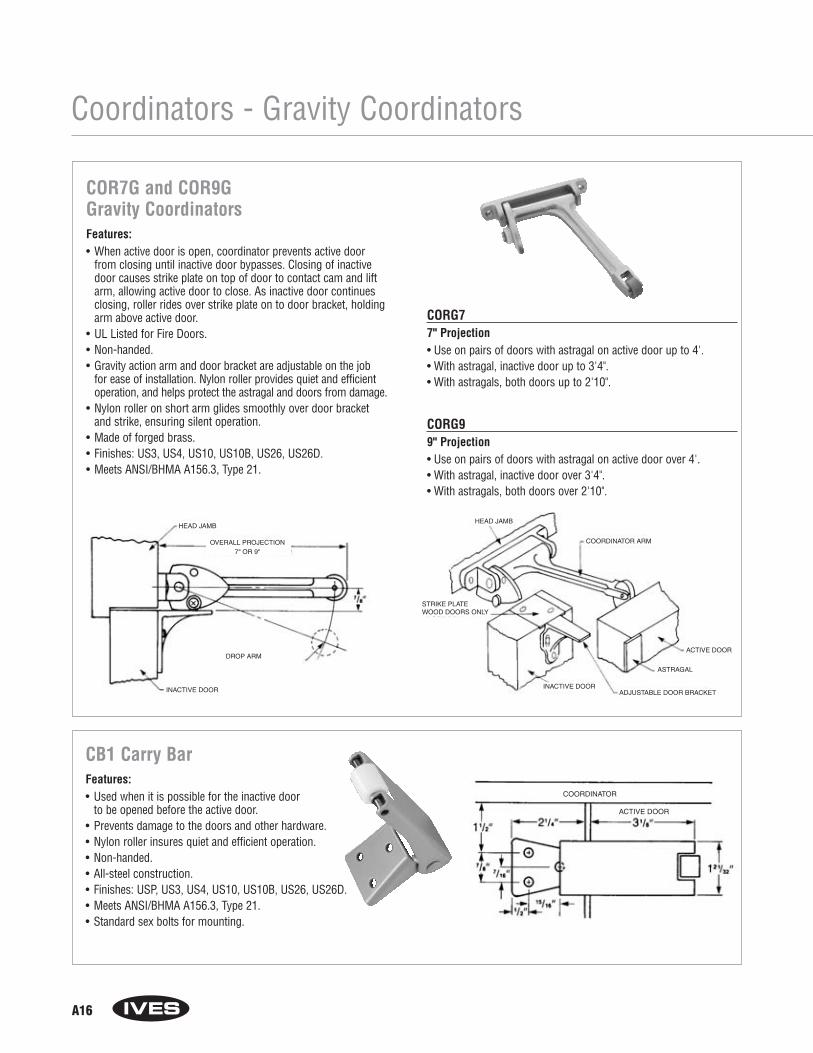
A16
COR7G and COR9G Gravity CoordinatorsFeatures:• When active door is open, coordinator prevents active door
from closing until inactive door bypasses. Closing of inactivedoor causes strike plate on top of door to contact cam and liftarm, allowing active door to close. As inactive door continuesclosing, roller rides over strike plate on to door bracket, holdingarm above active door.
• UL Listed for Fire Doors.• Non-handed.• Gravity action arm and door bracket are adjustable on the job
for ease of installation. Nylon roller provides quiet and efficientoperation, and helps protect the astragal and doors from damage.
• Nylon roller on short arm glides smoothly over door bracket and strike, ensuring silent operation.
• Made of forged brass.• Finishes: US3, US4, US10, US10B, US26, US26D.• Meets ANSI/BHMA A156.3, Type 21.
CORG77" Projection• Use on pairs of doors with astragal on active door up to 4'.• With astragal, inactive door up to 3'4".• With astragals, both doors up to 2'10".
CORG99" Projection• Use on pairs of doors with astragal on active door over 4'.• With astragal, inactive door over 3'4".• With astragals, both doors over 2'10".
Coordinators - Gravity Coordinators
CB1 Carry BarFeatures:• Used when it is possible for the inactive door
to be opened before the active door.• Prevents damage to the doors and other hardware.• Nylon roller insures quiet and efficient operation. • Non-handed.• All-steel construction.• Finishes: USP, US3, US4, US10, US10B, US26, US26D.• Meets ANSI/BHMA A156.3, Type 21.• Standard sex bolts for mounting.

Section BPivots
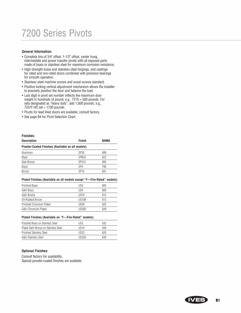
B1
7200 Series Pivots
General Information:• Complete line of 3/4" offset, 1-1/2" offset, center hung,
intermediate and power transfer pivots with all exposed parts made of brass or stainless steel for maximum corrosion resistance.
• High strength brass and stainless steel forgings, and castings for rated and non-rated doors combined with precision bearingsfor smooth operation.
• Stainless steel machine screws and wood screws standard.• Positive locking vertical adjustment mechanism allows the installer
to precisely position the door and balance the load.• Last digit in pivot set number reflects the maximum door
weight in hundreds of pound, e.g., 7215 = 500 pounds. For sets designated as “heavy duty”, add 1,000 pounds, e.g., 7237F HD set = 1700 pounds.
• Pivots for lead lined doors are available, consult factory.• See page B4 for Pivot Selection Chart.
Finishes:Description Finish BHMA
Powder-Coated Finishes (Available on all models)
Aluminum SP28 689Black SPBLK 622Dark Bronze SP313 695Brass SP4 706Bronze SP10 691
Plated Finishes (Available on all models except “F—Fire-Rated” models)
Polished Brass US3 605Satin Brass US4 606Satin Bronze US10 612Oil-Rubbed Bronze US10B 613Polished Chromium Plated US26 625Satin Chromium Plated US26D 626
Plated Finishes (Available on “F—Fire-Rated” models)
Polished Brass on Stainless Steel US3 632Plated Satin Bronze on Stainless Steel US10 639Polished Stainless Steel US32 629Satin Stainless Steel US32D 630
Optional Finishes:
Consult factory for availability. Special powder-coated finishes are available.

B2
7200 Series Pivots - Overview
3/4" Offset Pivots - 200 Lb. Doors
3/4" Offset Pivots - Standard and Fire-Rated - 500 to 700 Lb. Doors
3/4" Offset Pivots - Fire-Rated - 1000 to 1750 Lb. Doors
7212-7215-7222-7226-7227 Top Pivot
7212-7215-7222-7226-7227 Top Pivot7215F-7226F-7227F Top Pivot
7230F-7237F Top Pivot
7212 Bottom Pivot
7212V Top Pivot Optional
Optional
Optional
7212Bottom Pivot
7212V PIVOT SET
7212-7212V-7222Intermediate Pivot
7212 PIVOT SET 7222 PIVOT SET
7222Bottom Pivot
7215 Bottom Pivot7215F Bottom Pivot
7227-7227F-Bottom Pivot
7230FBottom Pivot
7237FBottom Pivot
7215-7226-7227PTPower Transfer
Intermediate Pivot
7230F-7237FIntermediate Pivot
7226-Bottom Pivot7226F-Bottom Pivot
7215 OR 7215FPIVOT SET
7230FPIVOT SET
7237FPIVOT SET
7227 OR 7227FPIVOT SET
7215-7226-7227 Intermediate Pivot
7215F-7226F-7227F Intermediate Pivot
7226 OR 7226FPIVOT SET
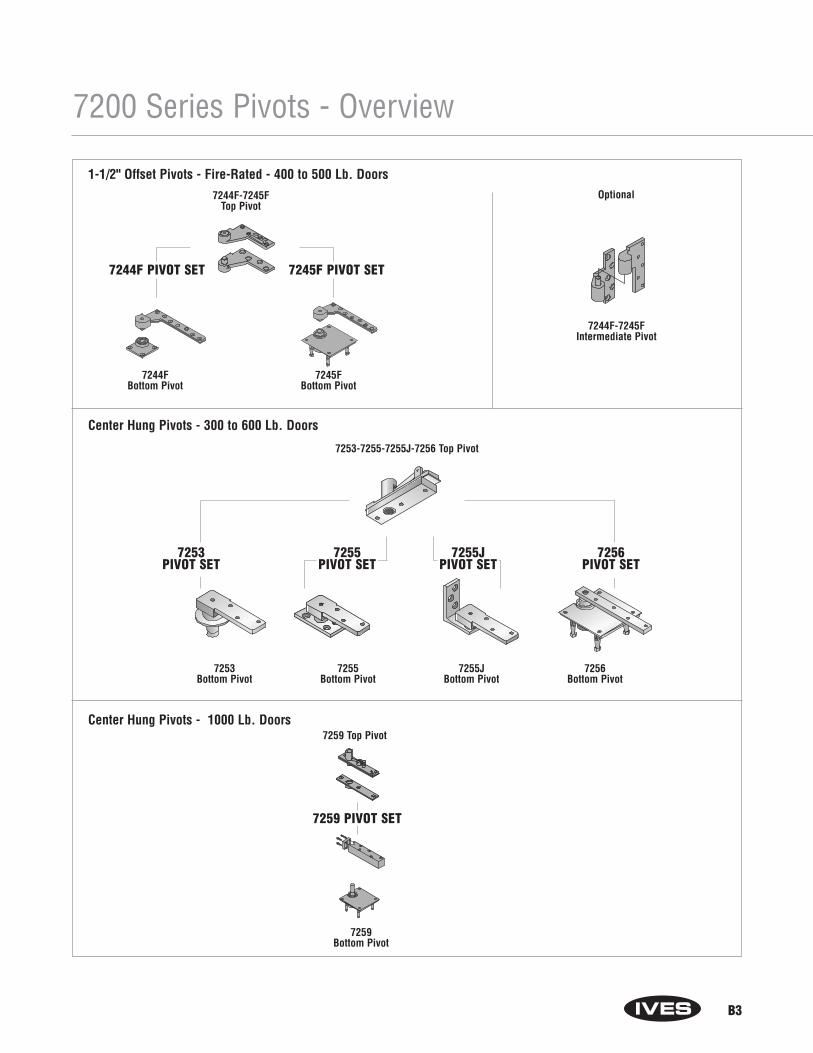
B3
7200 Series Pivots - Overview
1-1/2" Offset Pivots - Fire-Rated - 400 to 500 Lb. Doors
Center Hung Pivots - 300 to 600 Lb. Doors
Center Hung Pivots - 1000 Lb. Doors
7253Bottom Pivot
7255Bottom Pivot
7255JBottom Pivot
7256Bottom Pivot
7253-7255-7255J-7256 Top Pivot
7259 Top Pivot
7259Bottom Pivot
7256PIVOT SET
7255JPIVOT SET
7255PIVOT SET
7253PIVOT SET
7244F-7245FTop Pivot
7244F Bottom Pivot
Optional
7244F-7245FIntermediate Pivot
7244F PIVOT SET 7245F PIVOT SET
7245FBottom Pivot
7259 PIVOT SET

B4
7200 Series Pivot Selection ChartPivot UL Top Bottom Bottom Pivot Recommended 3/4" 1-1/2" Center Max Door HandedSet Rating Pivot Pivot Mounting Intermediate Pivot Offset Offset Hung Weight
7212 None 7212-7215-7222-7226-7227 7212 BTM Jamb 7212-7212V-7222 Yes 200 YesTOP Mounted INT
7212V None 7212V 7212 BTM Jamb 7212-7212V-7222 Yes 200 YesTOP Mounted INT
7215 20 min 7212-7215-7222-7226-7227 7215 BTM Jamb 7215-7226-7227 Yes 500 YesTOP Mounted INT
7215F 3 hr 7215F-7226F-7227F 7215F BTM Jamb 7215F-7226F-7227F Yes 500 YesTOP Mounted INT
7222 None 7212-7215-7222-7226-7227 7222 BTM Floor 7212-7212V-7222 Yes 200 YesTOP Mounted INT
7226 20 min 7212-7215-7222-7226-7227 7226 BTM Floor 7215-7226-7227 Yes 600 NoTOP Mounted INT
7226F 3 hr 7215F-7226F-7227F 7226F BTM Floor 7215F-7226F-7227F Yes 600 NoTOP Mounted INT
7227 20 min 7212-7215-7222-7226-7227 7227 BTM Mortised 7215-7226-7227 Yes 700 NoTOP Cement Case INT
7227F 3 hr 7215F-7226F-7227F 7227 BTM Mortised 7215F-7226F-7227F Yes 700 NoTOP Cement Case INT
7230F 3 hr 7230F-7237F 7230F BTM Floor 7230F-7237F Yes 1000 NoTOP Mounted INT
7237F 3 hr 7230F-7237F 7237F BTM Mortised 7230F-7237F Yes 1750 NoTOP Cement Case INT
7244F 3 hr 7244F-7245F 7244F BTM Floor 7244F-7245F Yes 400 NoTOP Mounted INT
7245F 3 hr 7244F-7245F 7245F BTM Mortised 7244F-7245F Yes 500 NoTOP Cement Case INT
7253 None 7253-7255-7255J-7256 7253 BTM Floor None Yes 300 NoTOP Mounted
7255 None 7253-7255-7255J-7256 7255 BTM Floor None Yes 500 NoTOP Mounted
7255J None 7253-7255-7255J-7256 7255J BTM Jamb None Yes 500 NoTOP Mounted
7256 None 7253-7255-7255J-7256 7256 BTM Mortised None Yes 600 NoTOP Cement Case
7259 None 7259 7259 BTM Mortised None Yes 1000 NoTOP Cement Case
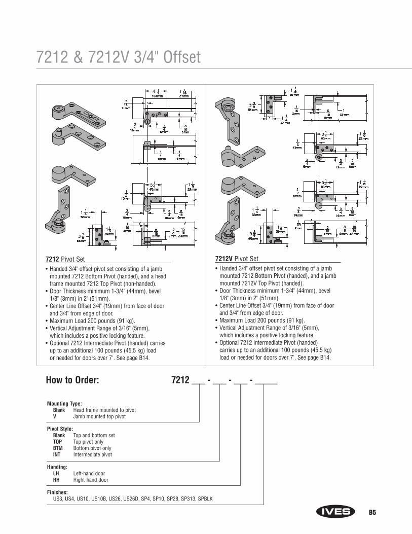
B5
7212V Pivot Set
7212 & 7212V 3/4" Offset
7212 Pivot Set• Handed 3/4" offset pivot set consisting of a jamb
mounted 7212 Bottom Pivot (handed), and a headframe mounted 7212 Top Pivot (non-handed).
• Door Thickness minimum 1-3/4" (44mm), bevel 1/8" (3mm) in 2" (51mm).
• Center Line Offset 3/4" (19mm) from face of door and 3/4" from edge of door.
• Maximum Load 200 pounds (91 kg).• Vertical Adjustment Range of 3/16" (5mm),
which includes a positive locking feature.• Optional 7212 Intermediate Pivot (handed) carries
up to an additional 100 pounds (45.5 kg) load or needed for doors over 7'. See page B14.
7212V Pivot Set• Handed 3/4" offset pivot set consisting of a jamb
mounted 7212 Bottom Pivot (handed), and a jambmounted 7212V Top Pivot (handed).
• Door Thickness minimum 1-3/4" (44mm), bevel1/8" (3mm) in 2" (51mm).
• Center Line Offset 3/4" (19mm) from face of door and 3/4" from edge of door.
• Maximum Load 200 pounds (91 kg).• Vertical Adjustment Range of 3/16" (5mm),
which includes a positive locking feature.• Optional 7212 intermediate Pivot (handed)
carries up to an additional 100 pounds (45.5 kg)load or needed for doors over 7'. See page B14.
Mounting Type: Blank Head frame mounted to pivotV Jamb mounted top pivot
Pivot Style: Blank Top and bottom setTOP Top pivot onlyBTM Bottom pivot onlyINT Intermediate pivot
Handing:LH Left-hand doorRH Right-hand door
Finishes: US3, US4, US10, US10B, US26, US26D, SP4, SP10, SP28, SP313, SPBLK
How to Order: 7212 ___ - ___ - ___ - _____

B6
7215 & 7215F 3/4" Offset
7215F Pivot Set
Rating: Blank Non-fire-rated F Fire-rated
Pivot Style: Blank Top and bottom setTOP Top pivot onlyBTM Bottom pivot onlyINT Intermediate pivot onlyPT INT Power transfer intermediate pivot only
Handing: LH Left-hand doorRH Right-hand door
Finishes: Non-Fire-Rated US3, US4, US10, US10B, US26, US26D, SP4, SP10, SP28, SP313, SPBLKFire-Rated US3, US10, US32, US32D, SP4, SP10, SP28, SP313, SPBLK
How to Order:7215 ___ - ___ - ___ - ____
7215 or 7215F Pivot Sets• Handed 3/4" offset pivot set consisting of a jamb
mounted 7215 or 7215F Bottom Pivot (handed) and a head frame mounted 7215 or 7215F Top Pivot,(non-handed).
• Door Thickness minimum 1-3/4" (44mm), bevel 1/8" (3mm) in 2" (51mm).
• Center Line Offset 3/4" (19mm) from face of door and 3/4" from edge of door.
• Maximum Load 500 pounds (227 kg).• UL Listed
7215 for 20 minute rated door.7215F for 3 hour rated door.
• 7215F meets ANSI/BHMA Grade 1.• Vertical Adjustment Range of 3/16" (5mm),
which includes a positive locking feature.• Optional Intermediate Pivot
For 7215 set use 7215 Intermediate Pivot (handed).For 7215F set use 7215 Intermediate Pivot (handed).Each Intermediate Pivot carries up to an additional 100 pounds (45.5 kg) load or needed for doors over 7'. See page B14.
• Optional 7215 PT Power Transfer Intermediate Pivot(handed). Provides 4 wire transfer with no weight bearing capabilities. See page B20.
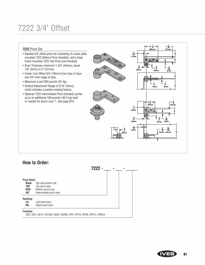
B7
7222 3/4" Offset
7222 Pivot Set• Handed 3/4" offset pivot set consisting of a base plate
mounted 7222 Bottom Pivot (handed), and a headframe mounted 7222 Top Pivot (non-handed).
• Door Thickness minimum 1-3/4" (44mm), bevel 1/8" (3mm) in 2" (51mm).
• Center Line Offset 3/4" (19mm) from face of door and 3/4" from edge of door.
• Maximum Load 200 pounds (91 kg).• Vertical Adjustment Range of 3/16" (5mm),
which includes a positive locking feature.• Optional 7222 Intermediate Pivot (handed) carries
up to an additional 100 pounds (45.5 kg) load or needed for doors over 7'. See page B14.
How to Order:7222 - ___ - ___ - _____
Pivot Style:Blank Top and bottom setTOP Top pivot onlyBTM Bottom pivot onlyINT Intermediate pivot only
Handing: LH Left-hand doorRH Right-hand door
Finishes: US3, US4, US10, US10B, US26, US26D, SP4, SP10, SP28, SP313, SPBLK
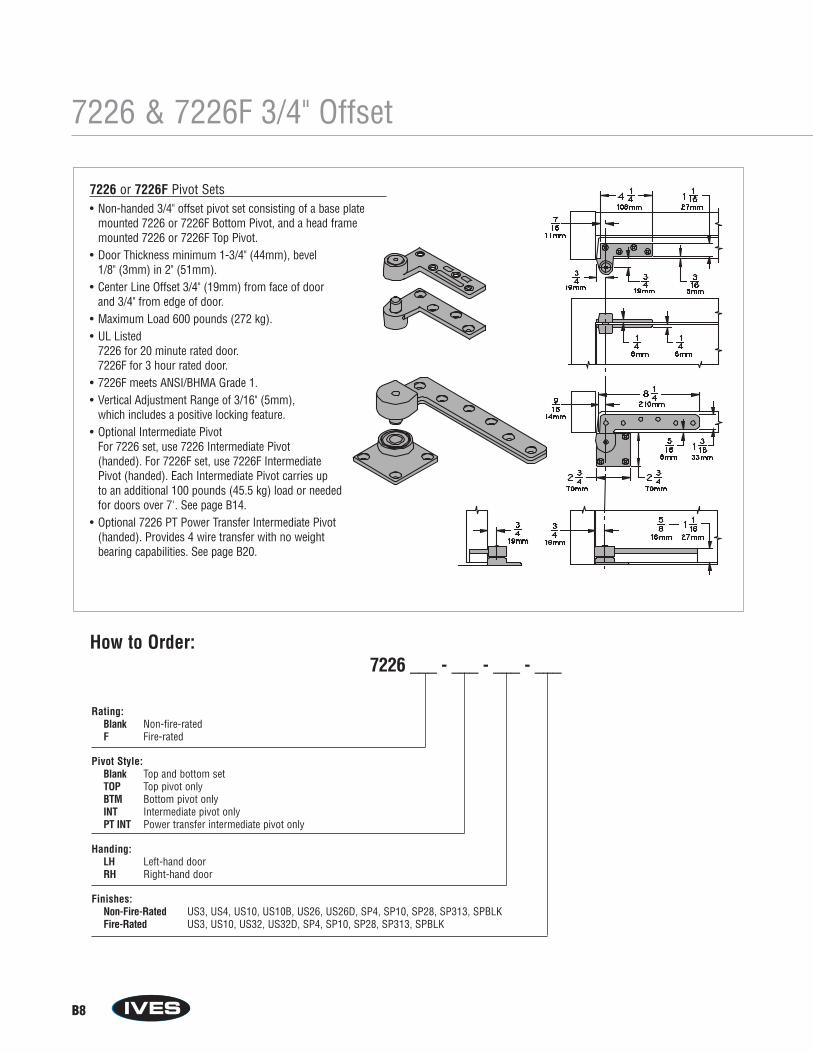
B8
7226 & 7226F 3/4" Offset
7226 Pivot Set7226F Pivot Set
How to Order:7226 ___ - ___ - ___ - ___
Rating: Blank Non-fire-rated F Fire-rated
Pivot Style: Blank Top and bottom setTOP Top pivot onlyBTM Bottom pivot onlyINT Intermediate pivot onlyPT INT Power transfer intermediate pivot only
Handing: LH Left-hand doorRH Right-hand door
Finishes: Non-Fire-Rated US3, US4, US10, US10B, US26, US26D, SP4, SP10, SP28, SP313, SPBLKFire-Rated US3, US10, US32, US32D, SP4, SP10, SP28, SP313, SPBLK
7226 or 7226F Pivot Sets• Non-handed 3/4" offset pivot set consisting of a base plate
mounted 7226 or 7226F Bottom Pivot, and a head framemounted 7226 or 7226F Top Pivot.
• Door Thickness minimum 1-3/4" (44mm), bevel 1/8" (3mm) in 2" (51mm).
• Center Line Offset 3/4" (19mm) from face of door and 3/4" from edge of door.
• Maximum Load 600 pounds (272 kg).• UL Listed
7226 for 20 minute rated door.7226F for 3 hour rated door.
• 7226F meets ANSI/BHMA Grade 1.• Vertical Adjustment Range of 3/16" (5mm),
which includes a positive locking feature.• Optional Intermediate Pivot
For 7226 set, use 7226 Intermediate Pivot (handed). For 7226F set, use 7226F Intermediate Pivot (handed). Each Intermediate Pivot carries up to an additional 100 pounds (45.5 kg) load or needed for doors over 7'. See page B14.
• Optional 7226 PT Power Transfer Intermediate Pivot (handed). Provides 4 wire transfer with no weight bearing capabilities. See page B20.

B9
7227 & 7227F 3/4" Offset
27F Pivot Set
Rating: Blank Non-fire-rated F Fire-rated
Pivot Style: Blank Top and bottom setTOP Top pivot onlyBTM Bottom pivot onlyINT Intermediate pivot onlyPT INT Power transfer intermediate pivot only
Handing: LH Left-hand doorRH Right-hand door
Finishes: Non-Fire-Rated US3, US4, US10, US10B, US26, US26D, SP4, SP10, SP28, SP313, SPBLKFire-Rated US3, US10, US32, US32D, SP4, SP10, SP28, SP313, SPBLK
How to Order:7227___ - ___ - ___ - ____
7227 or 7227F Pivot Sets• Non-handed 3/4" offset pivot set consisting of mortised
cement case mounted 7227 or 7227F Bottom Pivot and a head frame mounted 7227 or 7227F Top Pivot.
• Door Thickness minimum 1-3/4" (44mm), bevel 1/8" (3mm) in 2" (51mm).
• Center Line Offset 3/4" (19mm) from face of door and 3/4" from edge of door.
• Maximum Load 700 pounds (318 kg).• UL Listed
7227 for 20 minute rated door.7227F for 3 hour rated door.
• 7227F meets ANSI/BHMA Grade 1.• Vertical Adjustment Range of 3/16" (5mm),
which includes a positive locking feature.• Optional Intermediate Pivot
For 7227 set use 7227 Intermediate Pivot (handed).For 7227F set use 7227F Intermediate Pivot (handed).Each Intermediate Pivot carries up to an additional 100 pounds (45.5 kg) load or needed for doors over 7'. See page B14.
• Optional 7227 PT Power Transfer Intermediate Pivot(handed). Provides 4 wire transfer with no weight bearing capabilities. See page B20.
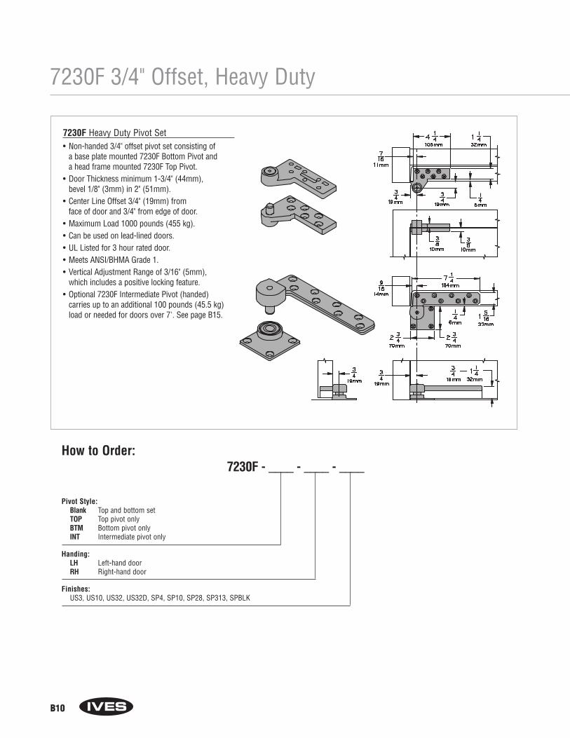
B10
7230F 3/4" Offset, Heavy Duty
How to Order:7230F - ____ - ____ - ____
Pivot Style:Blank Top and bottom setTOP Top pivot onlyBTM Bottom pivot onlyINT Intermediate pivot only
Handing: LH Left-hand doorRH Right-hand door
Finishes: US3, US10, US32, US32D, SP4, SP10, SP28, SP313, SPBLK
7230F Pivot Set7230F Heavy Duty Pivot Set• Non-handed 3/4" offset pivot set consisting of
a base plate mounted 7230F Bottom Pivot and a head frame mounted 7230F Top Pivot.
• Door Thickness minimum 1-3/4" (44mm), bevel 1/8" (3mm) in 2" (51mm).
• Center Line Offset 3/4" (19mm) from face of door and 3/4" from edge of door.
• Maximum Load 1000 pounds (455 kg).• Can be used on lead-lined doors.• UL Listed for 3 hour rated door.• Meets ANSI/BHMA Grade 1.• Vertical Adjustment Range of 3/16" (5mm),
which includes a positive locking feature.• Optional 7230F Intermediate Pivot (handed)
carries up to an additional 100 pounds (45.5 kg)load or needed for doors over 7'. See page B15.
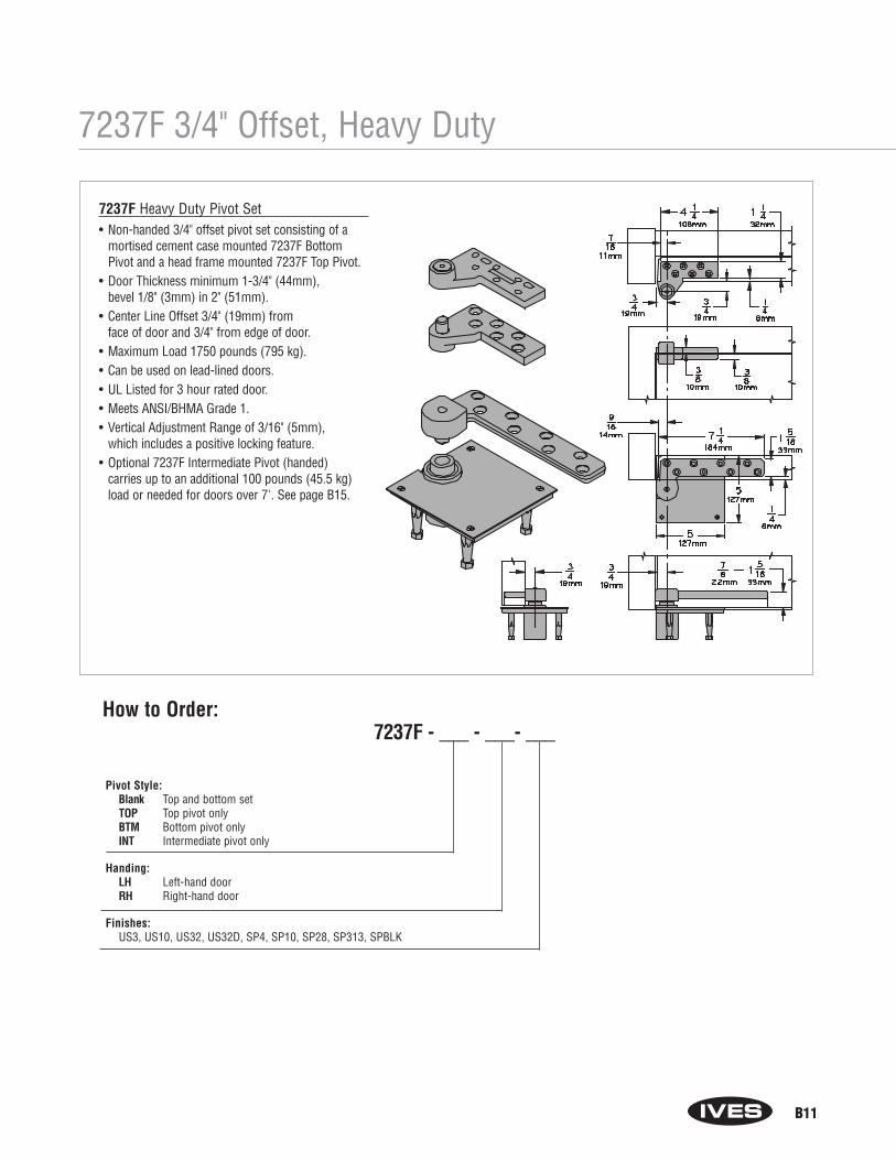
B11
7237F Pivot Set
7237F 3/4" Offset, Heavy Duty
How to Order:7237F - ___ - ___- ___
Pivot Style:Blank Top and bottom setTOP Top pivot onlyBTM Bottom pivot onlyINT Intermediate pivot only
Handing: LH Left-hand doorRH Right-hand door
Finishes: US3, US10, US32, US32D, SP4, SP10, SP28, SP313, SPBLK
7237F Heavy Duty Pivot Set• Non-handed 3/4" offset pivot set consisting of a
mortised cement case mounted 7237F BottomPivot and a head frame mounted 7237F Top Pivot.
• Door Thickness minimum 1-3/4" (44mm), bevel 1/8" (3mm) in 2" (51mm).
• Center Line Offset 3/4" (19mm) from face of door and 3/4" from edge of door.
• Maximum Load 1750 pounds (795 kg).• Can be used on lead-lined doors.• UL Listed for 3 hour rated door.• Meets ANSI/BHMA Grade 1.• Vertical Adjustment Range of 3/16" (5mm),
which includes a positive locking feature.• Optional 7237F Intermediate Pivot (handed)
carries up to an additional 100 pounds (45.5 kg)load or needed for doors over 7'. See page B15.
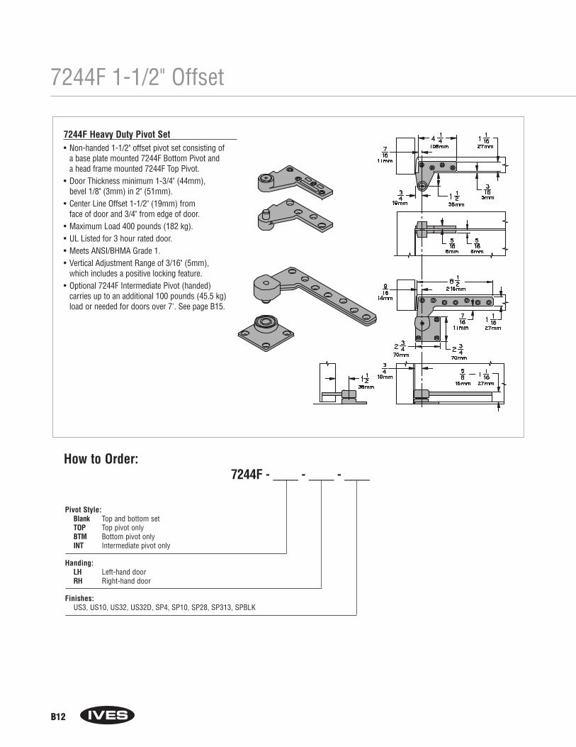
B12
7244F 1-1/2" Offset
7244F Heavy Duty Pivot Set• Non-handed 1-1/2" offset pivot set consisting of
a base plate mounted 7244F Bottom Pivot and a head frame mounted 7244F Top Pivot.
• Door Thickness minimum 1-3/4" (44mm), bevel 1/8" (3mm) in 2" (51mm).
• Center Line Offset 1-1/2" (19mm) from face of door and 3/4" from edge of door.
• Maximum Load 400 pounds (182 kg).• UL Listed for 3 hour rated door.• Meets ANSI/BHMA Grade 1.• Vertical Adjustment Range of 3/16" (5mm),
which includes a positive locking feature.• Optional 7244F Intermediate Pivot (handed)
carries up to an additional 100 pounds (45.5 kg)load or needed for doors over 7'. See page B15.
How to Order:7244F - ____ - ____ - ____
Pivot Style:Blank Top and bottom setTOP Top pivot onlyBTM Bottom pivot onlyINT Intermediate pivot only
Handing: LH Left-hand doorRH Right-hand door
Finishes: US3, US10, US32, US32D, SP4, SP10, SP28, SP313, SPBLK
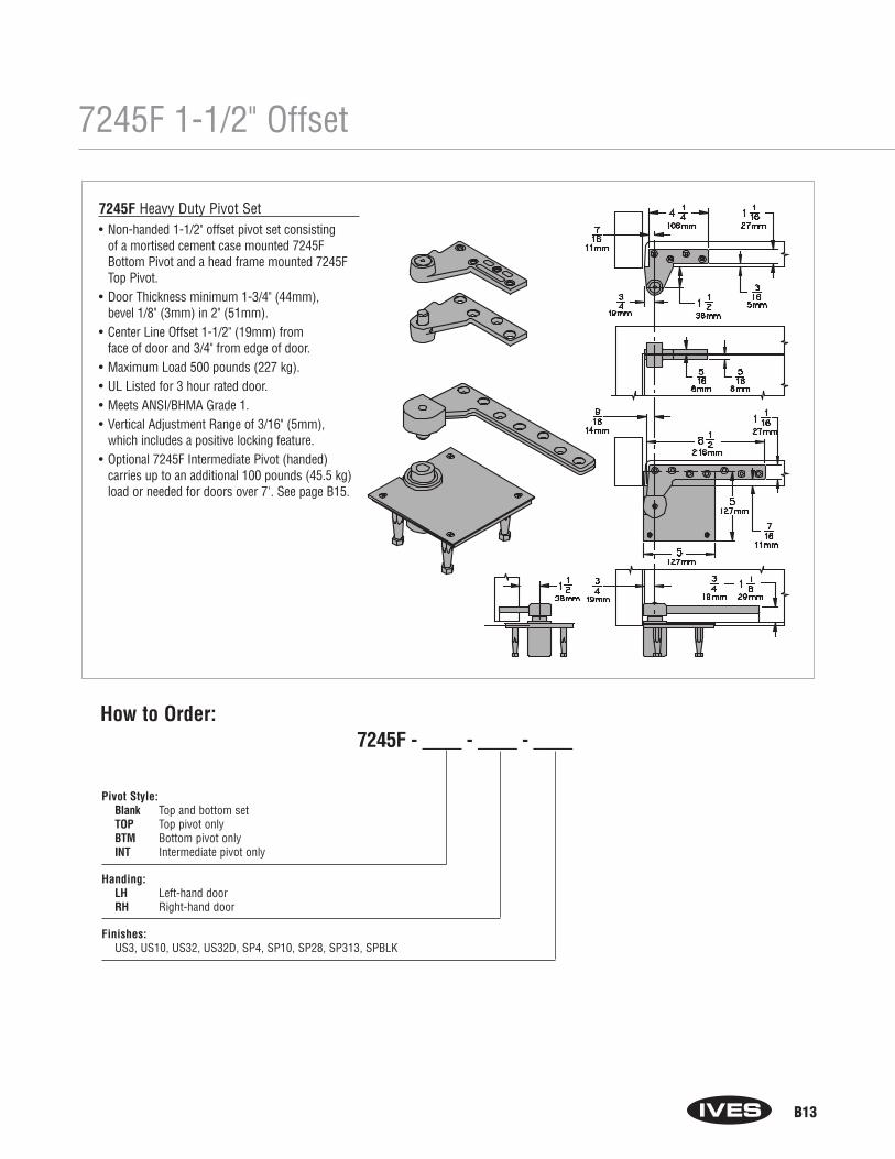
B13
7245F 1-1/2" Offset
7245F Heavy Duty Pivot Set• Non-handed 1-1/2" offset pivot set consisting
of a mortised cement case mounted 7245FBottom Pivot and a head frame mounted 7245FTop Pivot.
• Door Thickness minimum 1-3/4" (44mm), bevel 1/8" (3mm) in 2" (51mm).
• Center Line Offset 1-1/2" (19mm) from face of door and 3/4" from edge of door.
• Maximum Load 500 pounds (227 kg).• UL Listed for 3 hour rated door.• Meets ANSI/BHMA Grade 1.• Vertical Adjustment Range of 3/16" (5mm),
which includes a positive locking feature.• Optional 7245F Intermediate Pivot (handed)
carries up to an additional 100 pounds (45.5 kg)load or needed for doors over 7'. See page B15.
How to Order:7245F - ____ - ____ - ____
Pivot Style:Blank Top and bottom setTOP Top pivot onlyBTM Bottom pivot onlyINT Intermediate pivot only
Handing: LH Left-hand doorRH Right-hand door
Finishes: US3, US10, US32, US32D, SP4, SP10, SP28, SP313, SPBLK
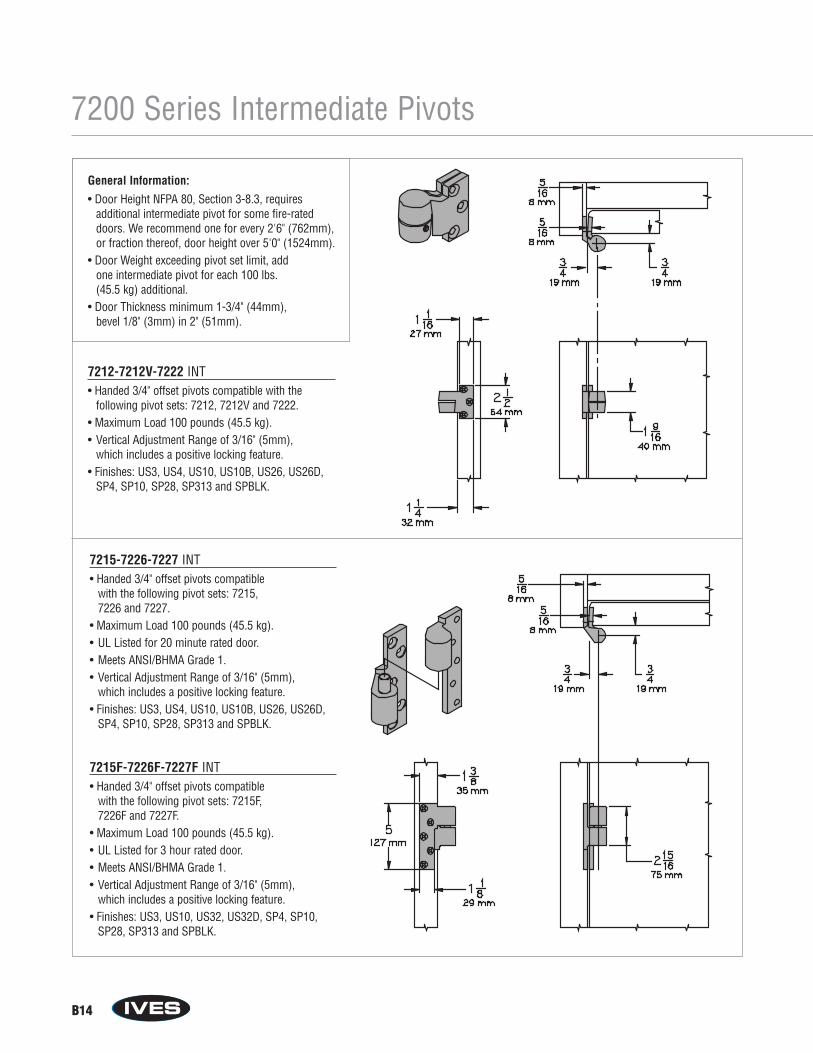
B14
7200 Series Intermediate Pivots
General Information:
• Door Height NFPA 80, Section 3-8.3, requires additional intermediate pivot for some fire-rateddoors. We recommend one for every 2'6" (762mm),or fraction thereof, door height over 5'0" (1524mm).
• Door Weight exceeding pivot set limit, add one intermediate pivot for each 100 lbs. (45.5 kg) additional.
• Door Thickness minimum 1-3/4" (44mm), bevel 1/8" (3mm) in 2" (51mm).
7212-7212V-7222 INT• Handed 3/4" offset pivots compatible with the
following pivot sets: 7212, 7212V and 7222.• Maximum Load 100 pounds (45.5 kg).• Vertical Adjustment Range of 3/16" (5mm),
which includes a positive locking feature.• Finishes: US3, US4, US10, US10B, US26, US26D,
SP4, SP10, SP28, SP313 and SPBLK.
15-7226-7227 INT15F-7226F-7227F INT
7215-7226-7227 INT• Handed 3/4" offset pivots compatible
with the following pivot sets: 7215, 7226 and 7227.
• Maximum Load 100 pounds (45.5 kg).• UL Listed for 20 minute rated door.• Meets ANSI/BHMA Grade 1.• Vertical Adjustment Range of 3/16" (5mm),
which includes a positive locking feature.• Finishes: US3, US4, US10, US10B, US26, US26D,
SP4, SP10, SP28, SP313 and SPBLK.
7215F-7226F-7227F INT• Handed 3/4" offset pivots compatible
with the following pivot sets: 7215F, 7226F and 7227F.
• Maximum Load 100 pounds (45.5 kg).• UL Listed for 3 hour rated door.• Meets ANSI/BHMA Grade 1.• Vertical Adjustment Range of 3/16" (5mm),
which includes a positive locking feature.• Finishes: US3, US10, US32, US32D, SP4, SP10,
SP28, SP313 and SPBLK.
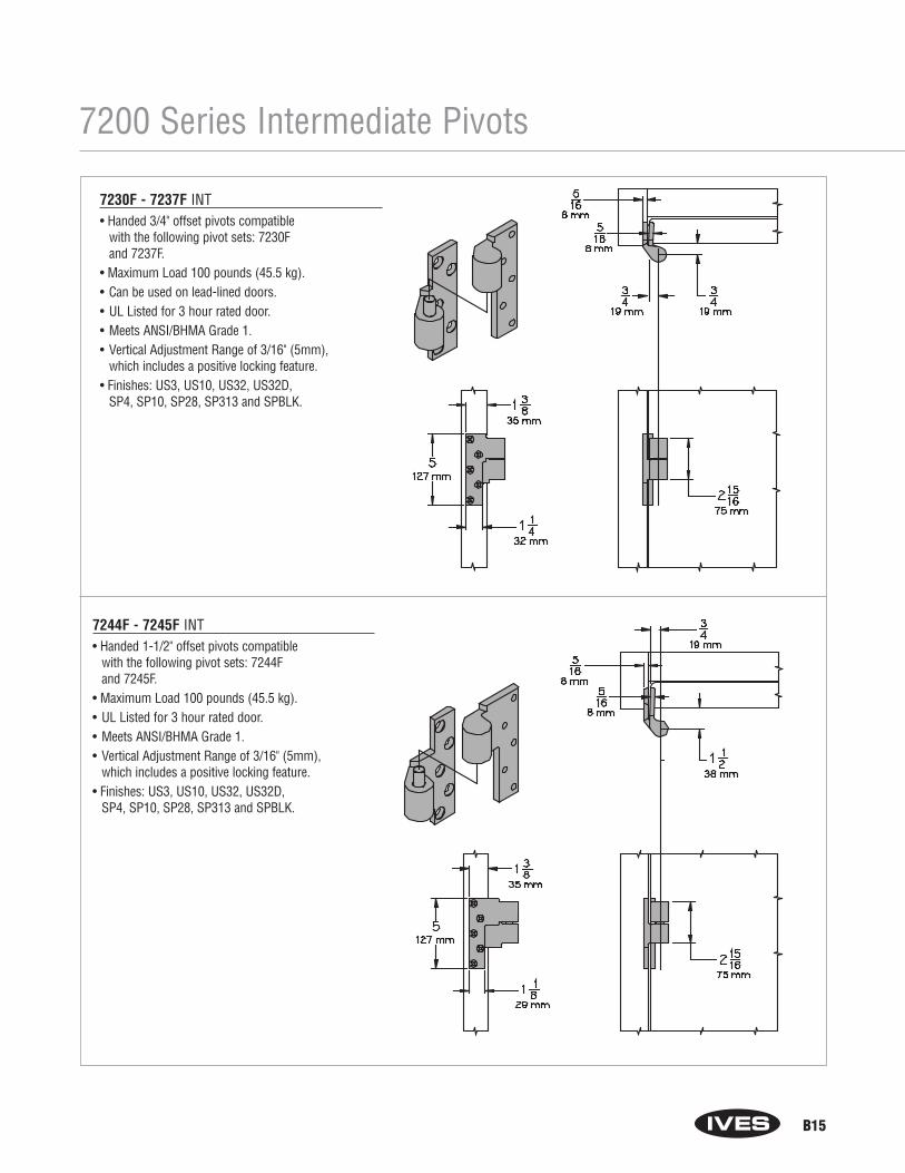
B15
7200 Series Intermediate Pivots
Intermediate Pivot7244F-7245F INT
0F 7237F INT
7244F - 7245F INT• Handed 1-1/2" offset pivots compatible
with the following pivot sets: 7244F and 7245F.
• Maximum Load 100 pounds (45.5 kg).• UL Listed for 3 hour rated door.• Meets ANSI/BHMA Grade 1.• Vertical Adjustment Range of 3/16" (5mm),
which includes a positive locking feature.• Finishes: US3, US10, US32, US32D,
SP4, SP10, SP28, SP313 and SPBLK.
7230F - 7237F INT• Handed 3/4" offset pivots compatible
with the following pivot sets: 7230F and 7237F.
• Maximum Load 100 pounds (45.5 kg).• Can be used on lead-lined doors.• UL Listed for 3 hour rated door.• Meets ANSI/BHMA Grade 1.• Vertical Adjustment Range of 3/16" (5mm),
which includes a positive locking feature.• Finishes: US3, US10, US32, US32D,
SP4, SP10, SP28, SP313 and SPBLK.
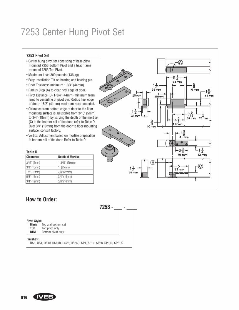
B16
7253 Pivot Set
7253 Center Hung Pivot Set
Table DClearance Depth of Mortise
3/16" (5mm) 1-3/16" (30mm)3/8" (10mm) 1" (25mm)1/2" (13mm) 7/8" (22mm)5/8" (16mm) 3/4" (19mm)3/4" (19mm) 5/8" (16mm)
How to Order:7253 - ___ - ____
Pivot Style:Blank Top and bottom setTOP Top pivot onlyBTM Bottom pivot only
Finishes: US3, US4, US10, US10B, US26, US26D, SP4, SP10, SP28, SP313, SPBLK
7253 Pivot Set• Center hung pivot set consisting of base plate
mounted 7253 Bottom Pivot and a head framemounted 7253 Top Pivot.
• Maximum Load 300 pounds (136 kg).• Easy Installation Tilt on bearing and bearing pin.• Door Thickness minimum 1-3/4" (44mm).• Radius Stop (A) to clear heel edge of door.• Pivot Distance (B) 1-3/4" (44mm) minimum from
jamb to centerline of pivot pin. Radius heel edge of door, 1-5/8" (41mm) minimum recommended.
• Clearance from bottom edge of door to the floormounting surface is adjustable from 3/16" (5mm) to 3/4" (19mm) by varying the depth of the mortise(C) in the bottom rail of the door, refer to Table D.Over 3/4" (19mm) from the door to floor mountingsurface, consult factory.
• Vertical Adjustment based on mortise preparation in bottom rail of the door. Refer to Table D.
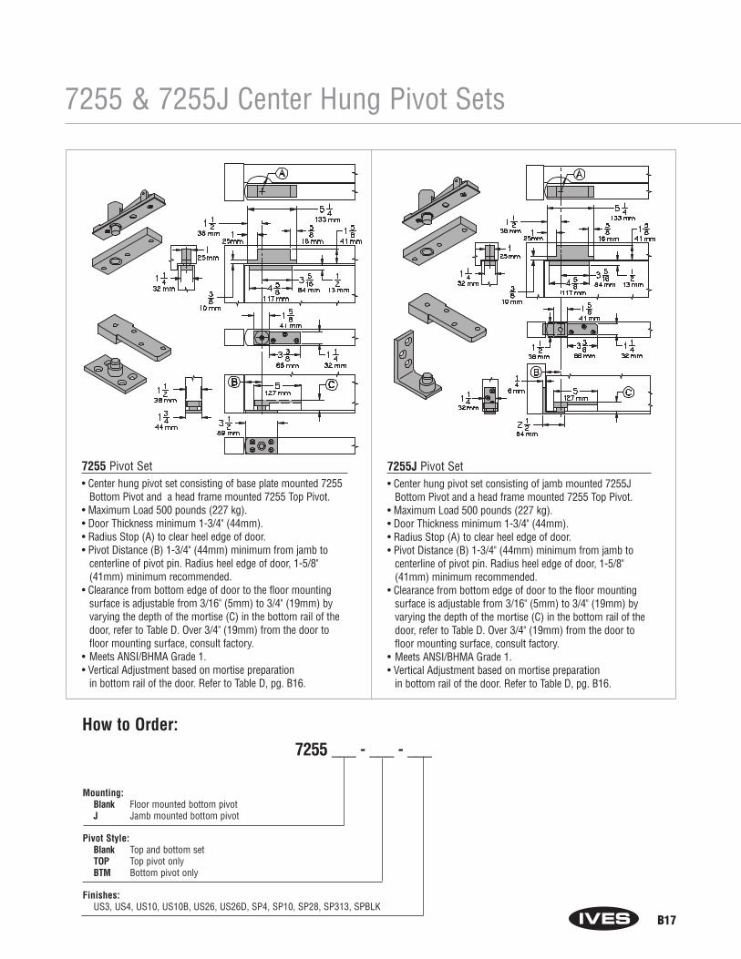
B17
7255 & 7255J Center Hung Pivot Sets
Mounting: Blank Floor mounted bottom pivotJ Jamb mounted bottom pivot
Pivot Style: Blank Top and bottom setTOP Top pivot onlyBTM Bottom pivot only
Finishes: US3, US4, US10, US10B, US26, US26D, SP4, SP10, SP28, SP313, SPBLK
How to Order:7255 ___ - ___ - ___
7255 Pivot Set• Center hung pivot set consisting of base plate mounted 7255
Bottom Pivot and a head frame mounted 7255 Top Pivot.• Maximum Load 500 pounds (227 kg).• Door Thickness minimum 1-3/4" (44mm).• Radius Stop (A) to clear heel edge of door.• Pivot Distance (B) 1-3/4" (44mm) minimum from jamb to
centerline of pivot pin. Radius heel edge of door, 1-5/8"(41mm) minimum recommended.
• Clearance from bottom edge of door to the floor mountingsurface is adjustable from 3/16" (5mm) to 3/4" (19mm) byvarying the depth of the mortise (C) in the bottom rail of thedoor, refer to Table D. Over 3/4" (19mm) from the door tofloor mounting surface, consult factory.
• Meets ANSI/BHMA Grade 1.• Vertical Adjustment based on mortise preparation
in bottom rail of the door. Refer to Table D, pg. B16.
7255J Pivot Set• Center hung pivot set consisting of jamb mounted 7255J
Bottom Pivot and a head frame mounted 7255 Top Pivot.• Maximum Load 500 pounds (227 kg).• Door Thickness minimum 1-3/4" (44mm).• Radius Stop (A) to clear heel edge of door.• Pivot Distance (B) 1-3/4" (44mm) minimum from jamb to
centerline of pivot pin. Radius heel edge of door, 1-5/8"(41mm) minimum recommended.
• Clearance from bottom edge of door to the floor mountingsurface is adjustable from 3/16" (5mm) to 3/4" (19mm) byvarying the depth of the mortise (C) in the bottom rail of thedoor, refer to Table D. Over 3/4" (19mm) from the door tofloor mounting surface, consult factory.
• Meets ANSI/BHMA Grade 1.• Vertical Adjustment based on mortise preparation
in bottom rail of the door. Refer to Table D, pg. B16.

B18
7256 Pivot Set
7256 Center Hung Pivot Set
Table DClearance Depth of Mortise
3/16" (5mm) 1-3/16" (30mm)3/8" (10mm) 1" (25mm)1/2" (13mm) 7/8" (22mm)5/8" (16mm) 3/4" (19mm)3/4" (19mm) 5/8" (16mm)
Pivot Style: Blank Top and bottom setTOP Top pivot onlyBTM Bottom pivot only
Finishes:US3, US4, US10, US10B, US26, US26D, SP4, SP10, SP28, SP313, SPBLK
How to Order:7256 - ___ - _____
7256 Pivot Set• Center hung pivot set consisting of mortised cement
case mounted 7256 Bottom Pivot and a head framemounted 7256 Top Pivot.
• Door Thickness minimum 1-3/4" (44mm).• Radius Stop (A) to clear heel edge of door.• Pivot Distance (B) 1-3/4" (44mm) minimum
from jamb to centerline of pivot pin. Radius heel edge of door, 1-5/8" (41mm) minimum recommended.
• Clearance from bottom edge of door to the floormounting surface is adjustable from 3/16" (5mm) to 3/4" (19mm) by varying the depth of the mortise(C) in the bottom rail of the door, refer to Table D.Over 3/4" (19mm) from the door to floor mountingsurface, consult factory.
• Maximum Load 600 pounds (272 kg).• Meets ANSI/BHMA Grade 1.• Vertical Adjustment based on mortise preparation
in bottom rail of the door. Refer to Table D.
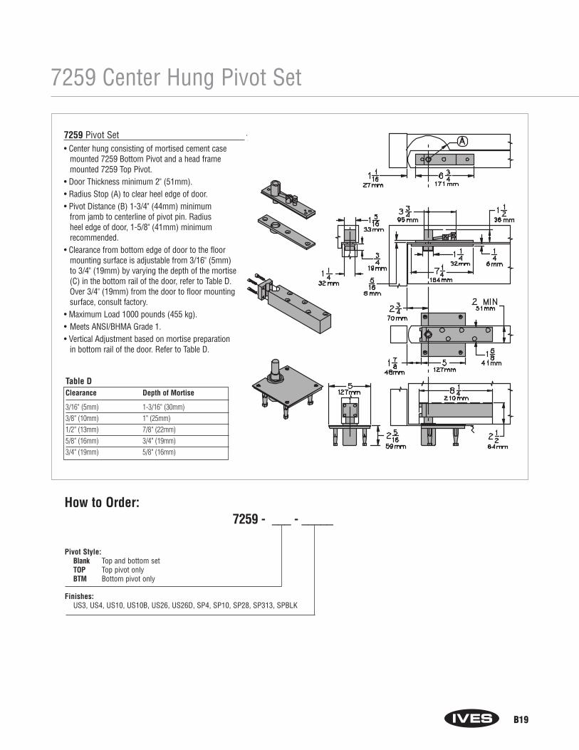
B19
7259 Pivot Set
7259 Center Hung Pivot Set
7259 Pivot Set• Center hung consisting of mortised cement case
mounted 7259 Bottom Pivot and a head framemounted 7259 Top Pivot.
• Door Thickness minimum 2" (51mm).• Radius Stop (A) to clear heel edge of door.• Pivot Distance (B) 1-3/4" (44mm) minimum
from jamb to centerline of pivot pin. Radius heel edge of door, 1-5/8" (41mm) minimum recommended.
• Clearance from bottom edge of door to the floormounting surface is adjustable from 3/16" (5mm) to 3/4" (19mm) by varying the depth of the mortise(C) in the bottom rail of the door, refer to Table D.Over 3/4" (19mm) from the door to floor mountingsurface, consult factory.
• Maximum Load 1000 pounds (455 kg). • Meets ANSI/BHMA Grade 1.• Vertical Adjustment based on mortise preparation
in bottom rail of the door. Refer to Table D.
Table DClearance Depth of Mortise
3/16" (5mm) 1-3/16" (30mm)3/8" (10mm) 1" (25mm)1/2" (13mm) 7/8" (22mm)5/8" (16mm) 3/4" (19mm)3/4" (19mm) 5/8" (16mm)
How to Order:7259 - ___ - _____
Pivot Style: Blank Top and bottom setTOP Top pivot onlyBTM Bottom pivot only
Finishes:US3, US4, US10, US10B, US26, US26D, SP4, SP10, SP28, SP313, SPBLK
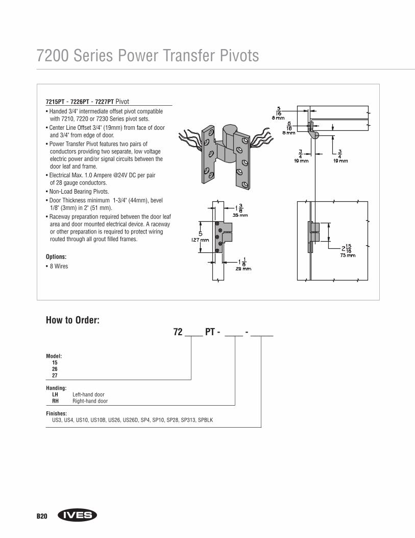
B20
7200 Series Power Transfer Pivots
7215PT - 7226PT - 7227PT Pivot• Handed 3/4" intermediate offset pivot compatible
with 7210, 7220 or 7230 Series pivot sets.• Center Line Offset 3/4" (19mm) from face of door
and 3/4" from edge of door.• Power Transfer Pivot features two pairs of
conductors providing two separate, low voltage electric power and/or signal circuits between thedoor leaf and frame.
• Electrical Max. 1.0 Ampere @24V DC per pair of 28 gauge conductors.
• Non-Load Bearing Pivots.• Door Thickness minimum 1-3/4" (44mm), bevel
1/8" (3mm) in 2" (51 mm).• Raceway preparation required between the door leaf
area and door mounted electrical device. A racewayor other preparation is required to protect wiringrouted through all grout filled frames.
Options:
• 8 Wires
Model: 152627
Handing: LH Left-hand doorRH Right-hand door
Finishes:US3, US4, US10, US10B, US26, US26D, SP4, SP10, SP28, SP313, SPBLK
How to Order:72 ____ PT - ____ - _____
Power Transfer Intermediate Pivot7215-7226-7227 PT
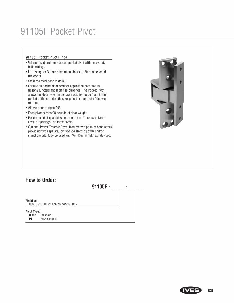
B21
91105F Pocket Pivot
91105F Pocket Pivot Hinge• Full mortised and non-handed pocket pivot with heavy duty
ball bearings.• UL Listing for 3 hour rated metal doors or 20 minute wood
fire doors.• Stainless steel base material.• For use on pocket door corridor application common in
hospitals, hotels and high rise buildings. The Pocket Pivotallows the door when in the open position to be flush in thepocket of the corridor, thus keeping the door out of the way of traffic.
• Allows door to open 90°.• Each pivot carries 90 pounds of door weight.• Recommended quantities per door up to 7' are two pivots.
Over 7' openings use three pivots.• Optional Power Transfer Pivot, features two pairs of conductors
providing two separate, low voltage electric power and/or signal circuits. May be used with Von Duprin “EL” exit devices.
Finishes:US3, US10, US32, US32D, SP313, USP
Pivot Type: Blank StandardPT Power transfer
How to Order:91105F - _____ - ______
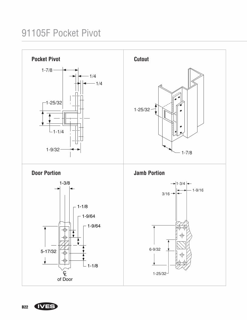
B22
91105F Pocket Pivot
1-3/8
1-1/8
1-1/8
5-17/32
1-9/64
1-9/64
CLof Door
Door Portion Jamb Portion
Pocket Pivot Cutout

B23
Notes

B24
Notes
Section CArchitectural Door Trim
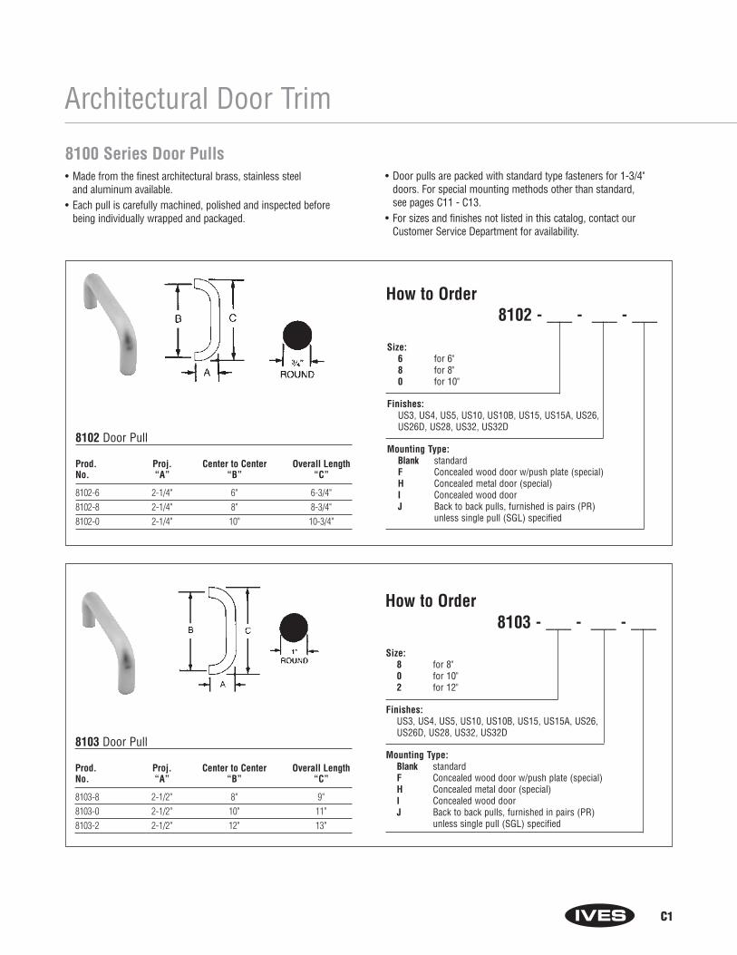
C1
Architectural Door Trim
8100 Series Door Pulls• Made from the finest architectural brass, stainless steel
and aluminum available.• Each pull is carefully machined, polished and inspected before
being individually wrapped and packaged.
• Door pulls are packed with standard type fasteners for 1-3/4"doors. For special mounting methods other than standard, see pages C11 - C13.
• For sizes and finishes not listed in this catalog, contact ourCustomer Service Department for availability.
8102 Door Pull
Prod. Proj. Center to Center Overall LengthNo. “A” “B” “C”
8102-6 2-1/4" 6" 6-3/4"8102-8 2-1/4" 8" 8-3/4"8102-0 2-1/4" 10" 10-3/4"
8103 Door Pull
Prod. Proj. Center to Center Overall LengthNo. “A” “B” “C”
8103-8 2-1/2" 8" 9"8103-0 2-1/2" 10" 11"8103-2 2-1/2" 12" 13"
How to Order8102 - ___ - ___ - ___
Size: 6 for 6"8 for 8"0 for 10"
Finishes: US3, US4, US5, US10, US10B, US15, US15A, US26, US26D, US28, US32, US32D
Mounting Type: Blank standardF Concealed wood door w/push plate (special)H Concealed metal door (special)I Concealed wood doorJ Back to back pulls, furnished is pairs (PR)
unless single pull (SGL) specified
How to Order8103 - ___ - ___ - ___
Size:8 for 8"0 for 10"2 for 12"
Finishes: US3, US4, US5, US10, US10B, US15, US15A, US26,US26D, US28, US32, US32D
Mounting Type: Blank standardF Concealed wood door w/push plate (special)H Concealed metal door (special)I Concealed wood doorJ Back to back pulls, furnished in pairs (PR)
unless single pull (SGL) specified
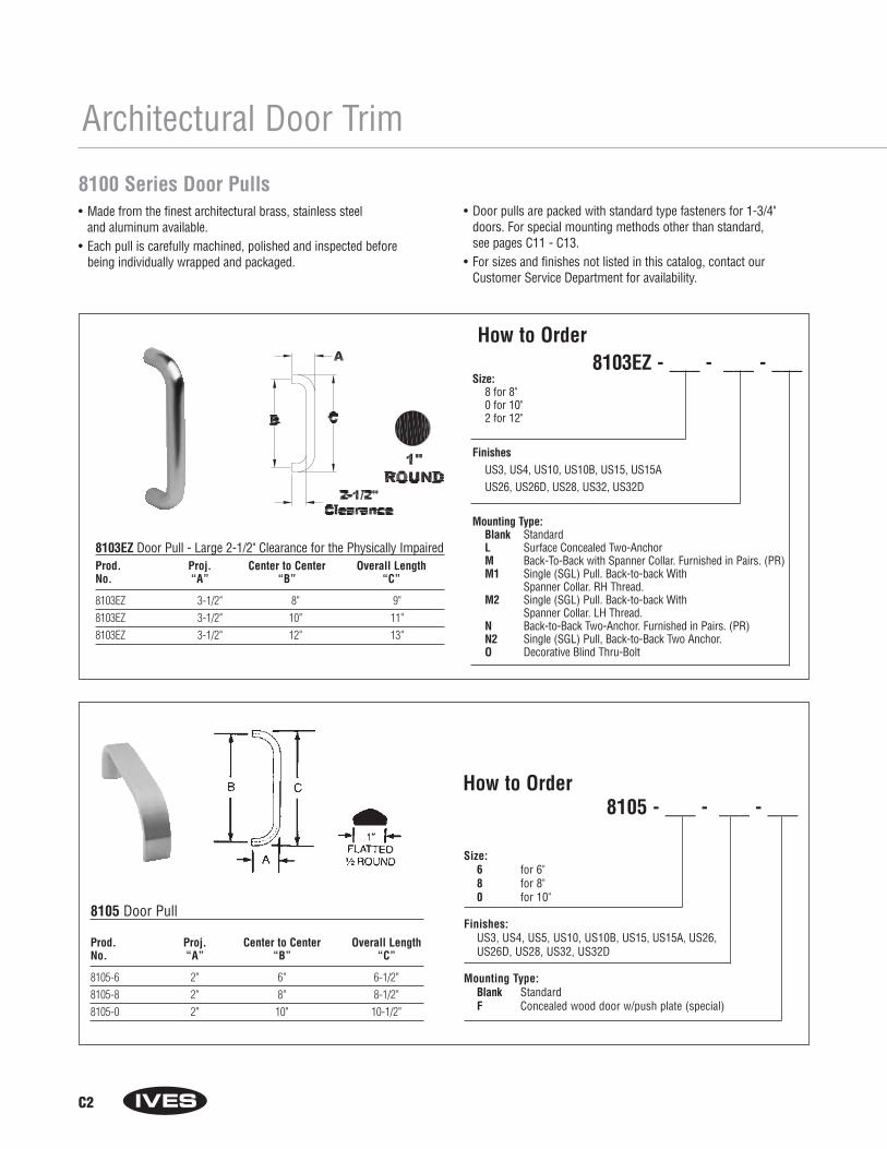
C2
Architectural Door Trim
How to Order8105 - ___ - ___ - ___
Size: 6 for 6"8 for 8"0 for 10"
Finishes: US3, US4, US5, US10, US10B, US15, US15A, US26, US26D, US28, US32, US32D
Mounting Type: Blank StandardF Concealed wood door w/push plate (special)
8105 Door Pull
Prod. Proj. Center to Center Overall LengthNo. “A” “B” “C”
8105-6 2" 6" 6-1/2"8105-8 2" 8" 8-1/2"8105-0 2" 10" 10-1/2"
8100 Series Door Pulls• Made from the finest architectural brass, stainless steel
and aluminum available.• Each pull is carefully machined, polished and inspected before
being individually wrapped and packaged.
• Door pulls are packed with standard type fasteners for 1-3/4"doors. For special mounting methods other than standard, see pages C11 - C13.
• For sizes and finishes not listed in this catalog, contact ourCustomer Service Department for availability.
8103EZ Door Pull - Large 2-1/2" Clearance for the Physically ImpairedProd. Proj. Center to Center Overall LengthNo. “A” “B” “C”
8103EZ 3-1/2" 8" 9"8103EZ 3-1/2" 10" 11"8103EZ 3-1/2" 12" 13"
Size:8 for 8"0 for 10"2 for 12"
FinishesUS3, US4, US10, US10B, US15, US15A US26, US26D, US28, US32, US32D
Mounting Type:Blank StandardL Surface Concealed Two-Anchor M Back-To-Back with Spanner Collar. Furnished in Pairs. (PR)M1 Single (SGL) Pull. Back-to-back With
Spanner Collar. RH Thread.M2 Single (SGL) Pull. Back-to-back With
Spanner Collar. LH Thread.N Back-to-Back Two-Anchor. Furnished in Pairs. (PR)N2 Single (SGL) Pull, Back-to-Back Two Anchor.O Decorative Blind Thru-Bolt
How to Order8103EZ - ___ - ___ - ___
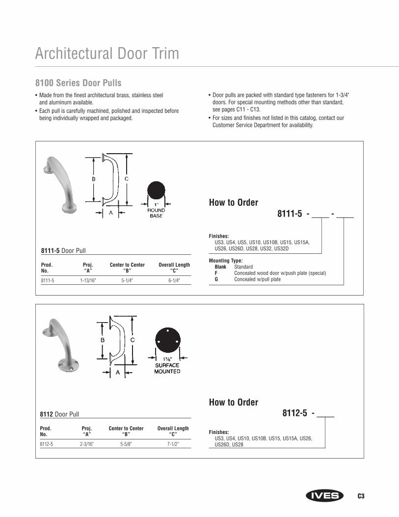
C3
How to Order8112-5 - ____
Finishes: US3, US4, US10, US10B, US15, US15A, US26, US26D, US28
8112 Door Pull
Prod. Proj. Center to Center Overall LengthNo. “A” “B” “C”
8112-5 2-3/16" 5-5/8" 7-1/2"
8100 Series Door Pulls• Made from the finest architectural brass, stainless steel
and aluminum available.• Each pull is carefully machined, polished and inspected before
being individually wrapped and packaged.
• Door pulls are packed with standard type fasteners for 1-3/4"doors. For special mounting methods other than standard, see pages C11 - C13.
• For sizes and finishes not listed in this catalog, contact ourCustomer Service Department for availability.
Architectural Door Trim
How to Order8111-5 - ____ - ____
Finishes: US3, US4, US5, US10, US10B, US15, US15A,US26, US26D, US28, US32, US32D
Mounting Type: Blank StandardF Concealed wood door w/push plate (special)G Concealed w/pull plate
8111-5 Door Pull
Prod. Proj. Center to Center Overall LengthNo. “A” “B” “C”
8111-5 1-13/16" 5-1/4" 6-1/4"

C4
How to Order8114-5 -_____ - ____
8100 Series Door Pulls• Made from the finest architectural brass, stainless steel
and aluminum available.• Each pull is carefully machined, polished and inspected before
being individually wrapped and packaged.
• Door pulls are packed with standard type fasteners for 1-3/4"doors. For special mounting methods other than standard, see pages C11 - C13.
• For sizes and finishes not listed in this catalog, contact ourCustomer Service Department for availability.
8114 Door Pull
Prod. Proj. Center to Center Overall LengthNo. “A” “B” “C”
8114-5 1-11/16" 5-1/4" 6-3/16"
Architectural Door Trim
Finishes: US3, US4, US10, US10B, US15, US15A, US26, US26D, US28, US32D
Mounting Type: Blank StandardF Concealed wood door w/push plate (special)G Concealed w/pull plate
13/16"
How to Order8113-5 - ____ - ____
Finishes: US3, US4, US10, US10B, US15, US15A, US26, US26D, US28
Mounting Type:Blank StandardF Concealed wood door w/push plate (special)
8113 Door Pull
Prod. Proj. Center to Center Overall LengthNo. “A” “B” “C”
8113-5 2-3/16" 5-5/8" 7-1/2"
DISCONTINUED
DISCONTINUED
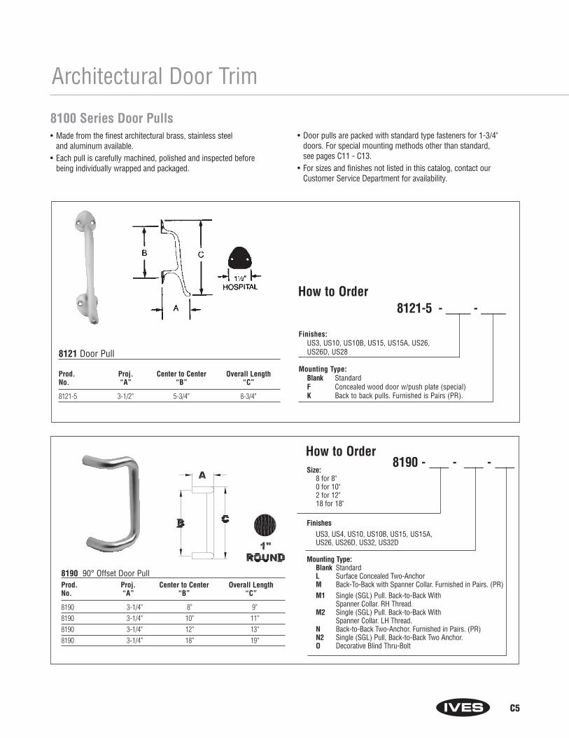
C5
How to Order8121-5 - ____ - ____
Finishes: US3, US10, US10B, US15, US15A, US26, US26D, US28
Mounting Type:Blank StandardF Concealed wood door w/push plate (special)K Back to back pulls. Furnished is Pairs (PR).
8121 Door Pull
Prod. Proj. Center to Center Overall LengthNo. “A” “B” “C”
8121-5 3-1/2" 5-3/4" 8-3/4"
Architectural Door Trim
8100 Series Door Pulls• Made from the finest architectural brass, stainless steel
and aluminum available.• Each pull is carefully machined, polished and inspected before
being individually wrapped and packaged.
• Door pulls are packed with standard type fasteners for 1-3/4"doors. For special mounting methods other than standard, see pages C11 - C13.
• For sizes and finishes not listed in this catalog, contact ourCustomer Service Department for availability.
8190 90° Offset Door PullProd. Proj. Center to Center Overall LengthNo. “A” “B” “C”
8190 3-1/4" 8" 9"8190 3-1/4" 10" 11"8190 3-1/4" 12" 13"8190 3-1/4" 18" 19"
Size:8 for 8"0 for 10"2 for 12"18 for 18"
FinishesUS3, US4, US10, US10B, US15, US15A, US26, US26D, US32, US32D
Mounting Type:Blank StandardL Surface Concealed Two-Anchor M Back-To-Back with Spanner Collar. Furnished in Pairs. (PR)M1 Single (SGL) Pull. Back-to-Back With
Spanner Collar. RH Thread.M2 Single (SGL) Pull. Back-to-Back With
Spanner Collar. LH Thread.N Back-to-Back Two-Anchor. Furnished in Pairs. (PR)N2 Single (SGL) Pull, Back-to-Back Two Anchor.O Decorative Blind Thru-Bolt
How to Order8190 - ___ - ___ - ___
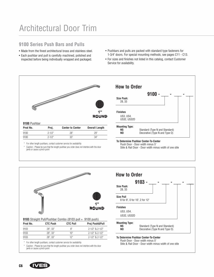
Architectural Door Trim
9103 Straight Pull/Pushbar Combo (8103 pull + 9100 push)Prod No. CTC Push CTC Pull Proj Push&Pull
9103 28", 33" 8" 2-1/2" & 2-1/2"9103 28", 33" 10" 2-1/2" & 2-1/2"9103 28", 33" 12" 2-1/2" & 2-1/2"
Size Push:28, 33
Size Pull8 for 8", 0 for 10", 2 for 12"
FinishesUS3, US4, US32, US32D
Mounting Type:NS Standard (Type N and Standard)NO Decorative (Type N and Type O)
To Determine Pushbar Center-To-CenterFlush Door - Door width minus 5"Stile & Rail Door - Door width minus width of one stile* For other length pushbars, contact customer service for avaliability
* Caution - Please be sure that the length pushbar you order does not interfere with the doorjamb or cause a pinch point
9100 PushbarProd No. Proj. Center to Center Overall Length
9100 2-1/2" 28" 29"9100 2-1/2" 33" 34"
Size Push:28, 33
FinishesUS3, US4, US32, US32D
Mounting Type:NS Standard (Type N and Standard)NO Decorative (Type N and Type O)
To Determine Pushbar Center-To-CenterFlush Door - Door width minus 5"Stile & Rail Door - Door width minus width of one stile
* For other length pushbars, contact customer service for avaliability* Caution - Please be sure that the length pushbar you order does not interfere with the door
jamb or cause a pinch point
C6
9100 Series Push Bars and Pulls• Made from the finest architectural brass and stainless steel.• Each pushbar and pull is carefully machined, polished and
inspected before being individually wrapped and packaged.
How to Order9100 - ___ - ___ - ___
How to Order9103 - ___ - ___ - ___ - ___
• Pushbars and pulls are packed with standard type fasteners for 1-3/4" doors. For special mounting methods, see pages C11 - C13.
• For sizes and finishes not listed in this catalog, contact CustomerService for availability.
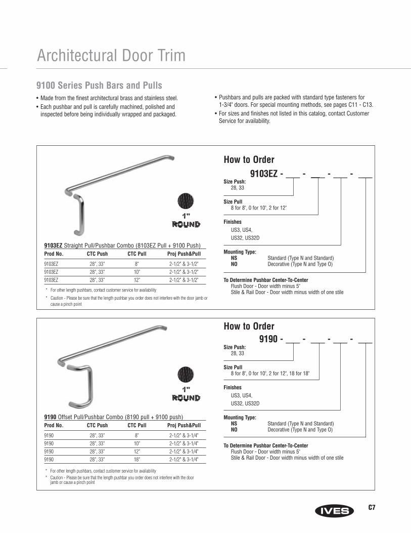
9190 Offset Pull/Pushbar Combo (8190 pull + 9100 push)Prod No. CTC Push CTC Pull Proj Push&Pull
9190 28", 33" 8" 2-1/2" & 3-1/4"9190 28", 33" 10" 2-1/2" & 3-1/4"9190 28", 33" 12" 2-1/2" & 3-1/4"9190 28", 33" 18" 2-1/2" & 3-1/4"
Size Push:28, 33
Size Pull8 for 8", 0 for 10", 2 for 12", 18 for 18"
FinishesUS3, US4,US32, US32D
Mounting Type:NS Standard (Type N and Standard)NO Decorative (Type N and Type O)
To Determine Pushbar Center-To-CenterFlush Door - Door width minus 5"Stile & Rail Door - Door width minus width of one stile
* For other length pushbars, contact customer service for avaliability* Caution - Please be sure that the length pushbar you order does not interfere with the door
jamb or cause a pinch point
Architectural Door Trim
9103EZ Straight Pull/Pushbar Combo (8103EZ Pull + 9100 Push)Prod No. CTC Push CTC Pull Proj Push&Pull
9103EZ 28", 33" 8" 2-1/2" & 3-1/2"9103EZ 28", 33" 10" 2-1/2" & 3-1/2"9103EZ 28", 33" 12" 2-1/2" & 3-1/2"
Size Push:28, 33
Size Pull8 for 8", 0 for 10", 2 for 12"
FinishesUS3, US4, US32, US32D
Mounting Type:NS Standard (Type N and Standard)NO Decorative (Type N and Type O)
To Determine Pushbar Center-To-CenterFlush Door - Door width minus 5"Stile & Rail Door - Door width minus width of one stile* For other length pushbars, contact customer service for avaliability
* Caution - Please be sure that the length pushbar you order does not interfere with the door jamb or cause a pinch point
9100 Series Push Bars and Pulls• Made from the finest architectural brass and stainless steel.• Each pushbar and pull is carefully machined, polished and
inspected before being individually wrapped and packaged.
• Pushbars and pulls are packed with standard type fasteners for 1-3/4" doors. For special mounting methods, see pages C11 - C13.
• For sizes and finishes not listed in this catalog, contact CustomerService for availability.
C7
How to Order9103EZ - ___ - ___ - ___ - ___
How to Order9190 - ___ - ___ - ___ - ___
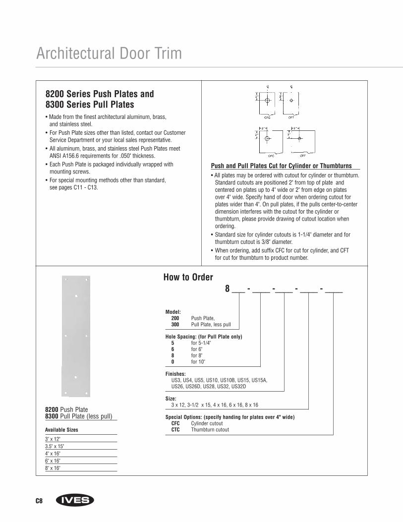
C8
Architectural Door Trim
How to Order8 ___ - ____ -____ - ____ - ____
Model: 200 Push Plate, 300 Pull Plate, less pull
Hole Spacing: (for Pull Plate only)5 for 5-1/4"6 for 6" 8 for 8"0 for 10"
Finishes: US3, US4, US5, US10, US10B, US15, US15A, US26, US26D, US28, US32, US32D
Size: 3 x 12, 3-1/2 x 15, 4 x 16, 6 x 16, 8 x 16
Special Options: (specify handing for plates over 4" wide)CFC Cylinder cutoutCTC Thumbturn cutout
8200 Series Push Plates and 8300 Series Pull Plates• Made from the finest architectural aluminum, brass,
and stainless steel.• For Push Plate sizes other than listed, contact our Customer
Service Department or your local sales representative.• All aluminum, brass, and stainless steel Push Plates meet
ANSI A156.6 requirements for .050" thickness.• Each Push Plate is packaged individually wrapped with
mounting screws.• For special mounting methods other than standard,
see pages C11 - C13.
8200 Push Plate8300 Pull Plate (less pull)
Available Sizes
3" x 12"3.5" x 15"4" x 16"6" x 16"8" x 16"
Push and Pull Plates Cut for Cylinder or Thumbturns• All plates may be ordered with cutout for cylinder or thumbturn.
Standard cutouts are positioned 2" from top of plate and centered on plates up to 4" wide or 2" from edge on plates over 4" wide. Specify hand of door when ordering cutout forplates wider than 4". On pull plates, if the pulls center-to-centerdimension interferes with the cutout for the cylinder or thumbturn, please provide drawing of cutout location whenordering.
• Standard size for cylinder cutouts is 1-1/4" diameter and forthumbturn cutout is 3/8" diameter.
• When ordering, add suffix CFC for cut for cylinder, and CFT for cut for thumbturn to product number.

How to Order 83 ____ - ____ - _____ - _____ - ____ - ____
Pull Style:02 for 810203 for 810305 for 8105
Pull Center to Center: 6 for 6" (not available on 8303) 8 for 8"0 for 10"
Finishes: US3, US4, US5, US10, US10B, US15, US15A, US26, US26D, US28, US32D
Size:3-1/2" x 15", 4" x 16", 6" x 16"
Special Options: (Handing needed for 6" x 16", LH or RH)CFC Cylinder cutoutCTC Thumbturn cutout
Mounting: Blank Standard F Concealed pull wood doors w/push plate (special. Not available 8303EZ.)G Concealed pull plate (Only available 8302, 8303 and 8303EZ)I Concealed pull wood door (not available 8305 and 8303EZ)J Back to back pull (not available 8305 and 8303EZ)
Architectural Door Trim
• 8300 Plate3-1/2" x 15"4" x 16"6" x 16"
• 8102 Pull6" centers8" centers10" centers
8302 Pull Plate• 8300 Plate
3-1/2" x 15"4" x 16"6" x 16"
• 8103 Pull8" centers10" centers
8303 and 8303EZ Pull Plate• 8300 Plate
3-1/2" x 15"4" x 16"6" x 16"
• 8105 Pull6" centers8" centers10" centers
8305 Pull Plate
8300 Series Pull Plates• Made from the finest architectural aluminum, brass
and stainless steel.• For Pull Plate sizes other than listed, contact our Customer Service
Department or your local sales representative.• All aluminum, brass, and stainless steel Pull Plates meet ANSI
A156.6 requirements for .050" thickness.
• Each Pull Plate is packaged individually wrapped with mounting screws.
• Pulls are centered on plates up to 4" wide and offset 2" from edgeof plates wider than 4".
• For special mounting methods other than standard, see pages C11 - C13.
C9

How to Order 83 ____ - 5 - ____ - ____ - ____- ____
Pull Style: 11 for 811114 for 8114
Finishes: US3, US4, US5, US10, US10B, US15, US15A, US26, US26D, US28, US32D
Size:3-1/2" x 15", 4" x 16", 6" x 16"
Special Options: (Handing needed for 6" x 16", LH or RH)CFC Cylinder cutoutCTC Thumbturn cutout
Mounting: Blank Standard F Concealed pull wood doors w/push plate (special)G Concealed pull plate
Architectural Door Trim
• 8300 Plate3-1/2" x 15"4" x 16"6" x 16"
• 8111-5 Pull5-1/4" centers
8311 Pull Plate• 8300 Plate
3-1/2" x 15"4" x 16"6" x 16"
• 8114-5 Pull5-1/4" centers
8314 Pull Plate
8300 Series Pull Plates• Made from the finest architectural aluminum, brass
and stainless steel.• For Pull Plate sizes other than listed, contact our Customer Service
Department or your local sales representative.• All aluminum, brass and stainless steel Pull Plates
meet ANSI A156.6 requirements for .050" thickness.
• Each Pull Plate is packaged individually wrapped with mounting screws.
• Pulls are centered on plates up to 4" wide and offset 2" from edge of plates wider than 4".
• For special mounting methods other than standard, see pagesC11 - C13.
C10
13/16"
DISCONTINUED
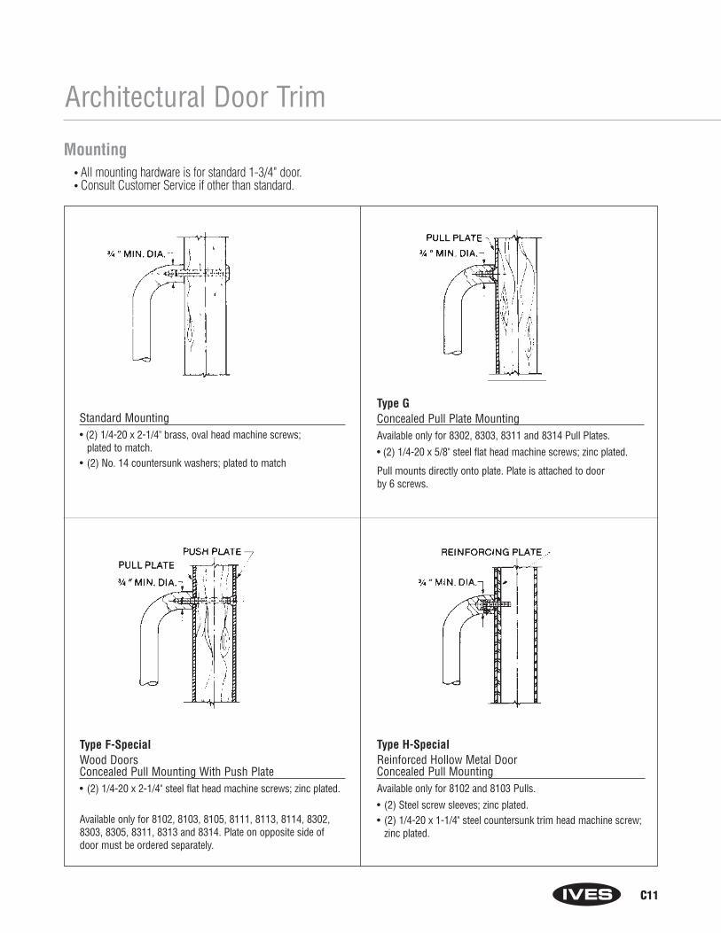
C11
Architectural Door Trim
Type F-SpecialWood DoorsConcealed Pull Mounting With Push Plate• (2) 1/4-20 x 2-1/4" steel flat head machine screws; zinc plated.
Available only for 8102, 8103, 8105, 8111, 8113, 8114, 8302, 8303, 8305, 8311, 8313 and 8314. Plate on opposite side of door must be ordered separately.
Standard Mounting• (2) 1/4-20 x 2-1/4" brass, oval head machine screws;
plated to match.• (2) No. 14 countersunk washers; plated to match
Type GConcealed Pull Plate MountingAvailable only for 8302, 8303, 8311 and 8314 Pull Plates.
• (2) 1/4-20 x 5/8" steel flat head machine screws; zinc plated.
Pull mounts directly onto plate. Plate is attached to door by 6 screws.
Type H-Special Reinforced Hollow Metal Door Concealed Pull MountingAvailable only for 8102 and 8103 Pulls.
• (2) Steel screw sleeves; zinc plated.• (2) 1/4-20 x 1-1/4" steel countersunk trim head machine screw;
zinc plated.
Mounting• All mounting hardware is for standard 1-3/4" door.• Consult Customer Service if other than standard.

C12
Architectural Door Trim
Type KBack to Back Pull MountingAvailable only for 8121-5 Pulls.
• (4) Steel screw sleeve nuts; steel zinc plated.• (8) No. 8-32 x 1" brass oval head machine screws; plated to
match.Pulls furnished in pairs (PR).
Type IWood DoorsConcealed Pull MountingAvailable only for 8102 and 8103 Pulls.
• (2) 10 x 1-1/2" No. 10 steel countersunk trim head sheet metal screws; zinc plated.
Type JBack to Back Pull MountingAvailable only for 8102, 8103, 8302 and 8303 Pulls.
• (2) Steel screw sleeves; zinc plated.• (2) 1/4-20 x 2-3/4" No. 10 steel countersunk trim head
machine screws; zinc plated.Pulls furnished in pairs (PR) unless single (SGL) specified.
Mounting• All mounting hardware is for standard 1-3/4" door.• Consult Customer Service if other than standard.
Type LReinforced Hollow Metal DoorAvailable only for 8103EZ and 8190 Pulls.
• (2) 1/4-20 x 1-1/4" steel countersunk trim head machine screwswith (4) set screws for maximum anchoring force
• (2) Steel screw sleeves; zinc plated.
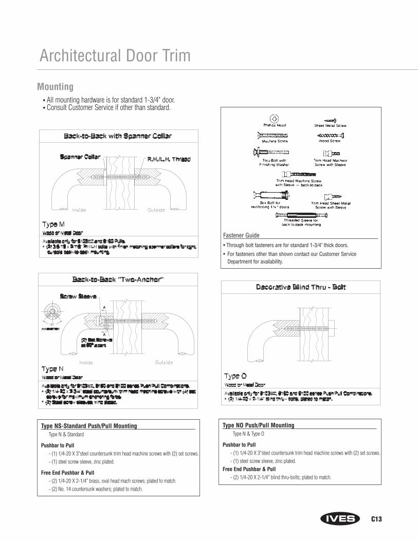
C13
Type NS-Standard Push/Pull MountingType N & Standard
Pushbar to Pull- (1) 1/4-20 X 3"steel countersunk trim head machine screws with (2) set screws.- (1) steel screw sleeve, zinc plated.
Free End Pushbar & Pull- (2) 1/4-20 X 2-1/4" brass, oval head mach screws; plated to match.- (2) No. 14 countersunk washers; plated to match.
Type NO Push/Pull MountingType N & Type O
Pushbar to Pull- (1) 1/4-20 X 3"steel countersunk trim head machine screws with (2) set screws.- (1) steel screw sleeve, zinc plated.
Free End Pushbar & Pull- (2) 1/4-20 X 2-1/4" blind thru-bolts; plated to match.
Architectural Door Trim
Fastener Guide
• Through bolt fasteners are for standard 1-3/4" thick doors.
• For fasteners other than shown contact our Customer ServiceDepartment for availability.
Mounting• All mounting hardware is for standard 1-3/4" door.• Consult Customer Service if other than standard.

C14
Architectural Door Trim
Mop Plates• Protect the bottom of the
pull side of door subject to cleaning and mopping procedures.
• Size Ranges:4" to 6" high, 22" to 48" wide
Kick Plates• Protect the bottom of the
push side of doors subject to scuffing from foot traffic.
• Recommended for all doors subject to normaluse (especially doors using a closer).
• Size Ranges:8" to 24" high, 22" to 48" wide
Stretcher Plates• Protect doors at specific
areas where consistent contact is made by stretchers, service carts or other equipment.
• Usually applied to push side of doors.
• Specify “B4E” Option forbeveled edges.
• Size Ranges:6" to 8" high, 22" to 48" wide
Armor Plates• Protect lower half of doors
from abuse by hard carts,trucks and rough usage.
• Usually applied to push sideof single doors and bothsides of double acting doors.
• Size Ranges:26" to 48" high, 22" to 48" wide
Series 8400 Door Protection Plates.050" ThicknessFeatures:• Door Protection Plates are fabricated from the finest architectural
aluminum, brass, and stainless steel, or 1/8" thick clear acrylicplastic or black or brown high impact polyethylene.
• All aluminum, brass, bronze and stainless steel Door ProtectionPlates meet ANSI A156.6 requirements for .050" thickness.
• Optional Beveling—For beveling of top and two sides of plates suffix with B3E, and for beveling of four sides suffix with B4E. Plastic plates are beveled on all four sides as standard.
• Each plate is packaged carefully wrapped in strong kraft paper with#6 x 5/8" oval head, undercut sheet metal screws plated to match,for easy installation on hollow metal, laminate, or wood doors. Allplates are packaged in heavy duty corrugated cardboard; largerplates are enclosed in a wooden frame.
• Use No. 8401 Kickplate Gasket Tape as a buffer between brasskickplates and metal doors to help prevent tarnishing which mayresult from electrolytic oxidation. One package provides enoughdouble-sided adhesive-backed foam tape for the perimeter of an 8" x 34" plate.
• Finishes:Brass: B3, B4, B5, B10, B10B (for heights over 24", check withcustomer serivce)Stainless Steel: S32D, S32Aluminum: PA28Plastic: BLK, BRN, CLR
How to Order 8400 ____ - _____ x _____ - _____Finish
Height: 4" up to 48" in 1/2" increments (For brass kick plates over 24", check with customer service.)
Width:22" up to 48" in 1/2" increments
Options: (Only for metal plates)B3E for Bevel Top and 2 EdgesB4E for Bevel 4 EdgesCS for Counter Sink HolesES for Extra row of Screws
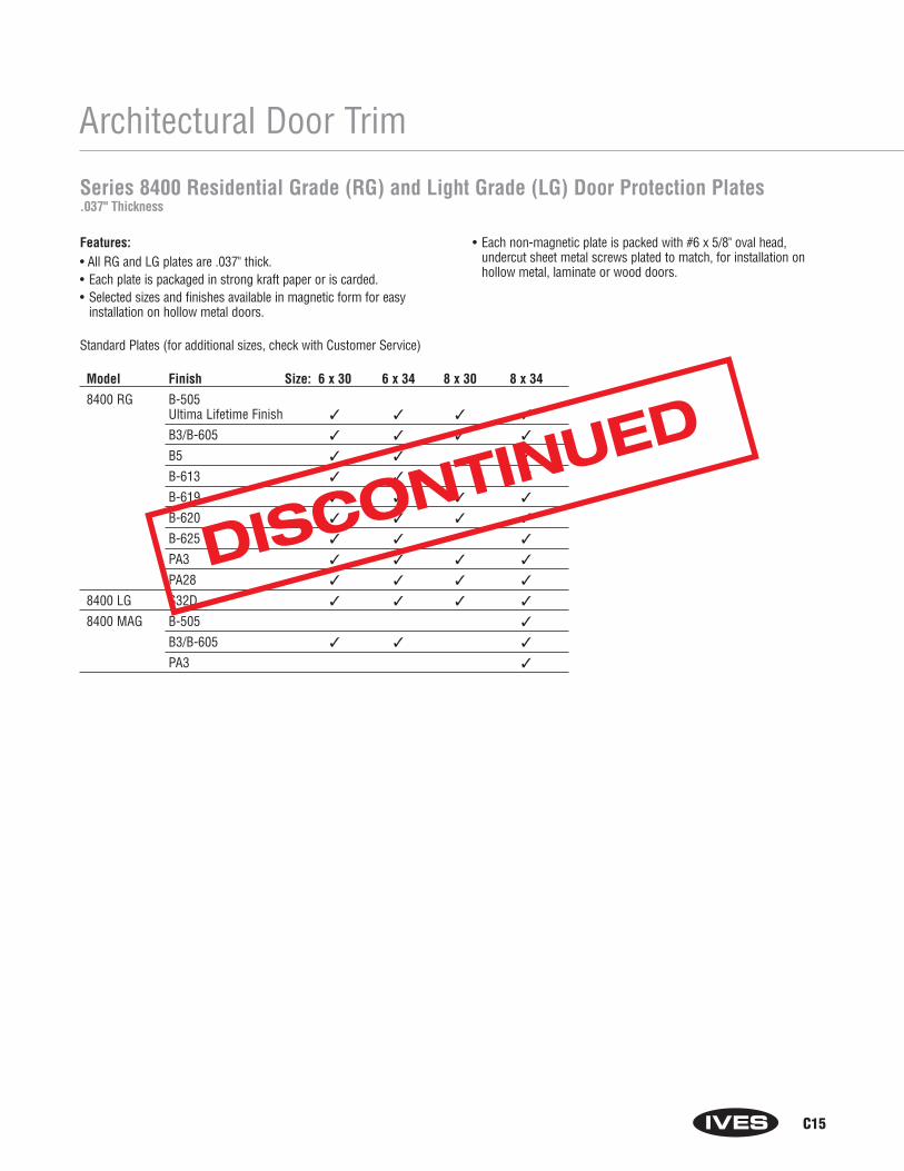
C15
Architectural Door Trim
Features:• All RG and LG plates are .037" thick.• Each plate is packaged in strong kraft paper or is carded.• Selected sizes and finishes available in magnetic form for easy
installation on hollow metal doors.
• Each non-magnetic plate is packed with #6 x 5/8" oval head, undercut sheet metal screws plated to match, for installation on hollow metal, laminate or wood doors.
Series 8400 Residential Grade (RG) and Light Grade (LG) Door Protection Plates.037" Thickness
Model Finish Size: 6 x 30 6 x 34 8 x 30 8 x 34
8400 RG B-505Ultima Lifetime Finish ✓ ✓ ✓ ✓
B3/B-605 ✓ ✓ ✓ ✓
B5 ✓ ✓ ✓
B-613 ✓ ✓ ✓
B-619 ✓ ✓ ✓ ✓
B-620 ✓ ✓ ✓ ✓
B-625 ✓ ✓ ✓
PA3 ✓ ✓ ✓ ✓
PA28 ✓ ✓ ✓ ✓
8400 LG S32D ✓ ✓ ✓ ✓
8400 MAG B-505 ✓
B3/B-605 ✓ ✓ ✓
PA3 ✓
Standard Plates (for additional sizes, check with Customer Service)
DISCONTINUED
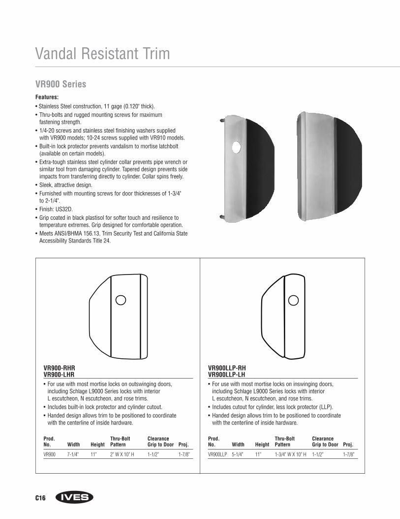
C16
Vandal Resistant Trim
VR900 SeriesFeatures:
• Stainless Steel construction, 11 gage (0.120" thick).• Thru-bolts and rugged mounting screws for maximum
fastening strength.• 1/4-20 screws and stainless steel finishing washers supplied
with VR900 models; 10-24 screws supplied with VR910 models.• Built-in lock protector prevents vandalism to mortise latchbolt
(available on certain models).• Extra-tough stainless steel cylinder collar prevents pipe wrench or
similar tool from damaging cylinder. Tapered design prevents sideimpacts from transferring directly to cylinder. Collar spins freely.
• Sleek, attractive design.• Furnished with mounting screws for door thicknesses of 1-3/4"
to 2-1/4".• Finish: US32D.• Grip coated in black plastisol for softer touch and resilience to
temperature extremes. Grip designed for comfortable operation.• Meets ANSI/BHMA 156.13, Trim Security Test and California State
Accessibility Standards Title 24.
VR900-RHR VR900-LHR• For use with most mortise locks on outswinging doors,
including Schlage L9000 Series locks with interior L escutcheon, N escutcheon, and rose trims.
• Includes built-in lock protector and cylinder cutout.• Handed design allows trim to be positioned to coordinate
with the centerline of inside hardware.
Prod. Thru-Bolt ClearanceNo. Width Height Pattern Grip to Door Proj.
VR900 7-1/4" 11" 2" W X 10" H 1-1/2" 1-7/8"
VR900LLP-RHVR900LLP-LH• For use with most mortise locks on inswinging doors,
including Schlage L9000 Series locks with interior L escutcheon, N escutcheon, and rose trims.
• Includes cutout for cylinder, less lock protector (LLP).• Handed design allows trim to be positioned to coordinate
with the centerline of inside hardware.
Prod. Thru-Bolt ClearanceNo. Width Height Pattern Grip to Door Proj.
VR900LLP 5-1/4" 11" 1-3/4" W X 10" H 1-1/2" 1-7/8"
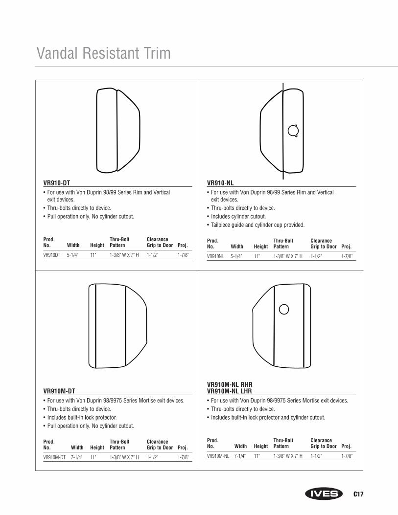
C17
Vandal Resistant Trim
VR910-DT• For use with Von Duprin 98/99 Series Rim and Vertical
exit devices.• Thru-bolts directly to device.• Pull operation only. No cylinder cutout.
Prod. Thru-Bolt ClearanceNo. Width Height Pattern Grip to Door Proj.
VR910DT 5-1/4" 11" 1-3/8" W X 7" H 1-1/2" 1-7/8"
VR910-NL• For use with Von Duprin 98/99 Series Rim and Vertical
exit devices.• Thru-bolts directly to device.• Includes cylinder cutout.• Tailpiece guide and cylinder cup provided.
Prod. Thru-Bolt ClearanceNo. Width Height Pattern Grip to Door Proj.
VR910NL 5-1/4" 11" 1-3/8" W X 7" H 1-1/2" 1-7/8"
VR910M-DT• For use with Von Duprin 98/9975 Series Mortise exit devices.• Thru-bolts directly to device.• Includes built-in lock protector.• Pull operation only. No cylinder cutout.
Prod. Thru-Bolt ClearanceNo. Width Height Pattern Grip to Door Proj.
VR910M-DT 7-1/4" 11" 1-3/8" W X 7" H 1-1/2" 1-7/8"
VR910M-NL RHRVR910M-NL LHR• For use with Von Duprin 98/9975 Series Mortise exit devices.• Thru-bolts directly to device.• Includes built-in lock protector and cylinder cutout.
Prod. Thru-Bolt ClearanceNo. Width Height Pattern Grip to Door Proj.
VR910M-NL 7-1/4" 11" 1-3/8" W X 7" H 1-1/2" 1-7/8"

C18
Notes
Section DFloor Stops,
Wall Stops and Bumpers
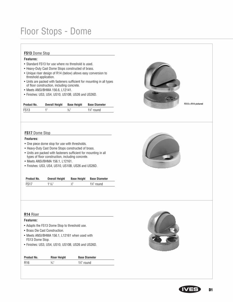
Floor Stops - Dome
R14 RiserFeatures:
• Adapts the FS13 Dome Stop to threshold use.• Brass Die Cast Construction.• Meets ANSI/BHMA 156.1, L12161 when used with
FS13 Dome Stop.• Finishes: US3, US4, US10, US10B, US26 and US26D.
D1
FS13 Dome StopFeatures:• Standard FS13 for use where no threshold is used.• Heavy-Duty Cast Dome Stops constructed of brass.• Unique riser design of R14 (below) allows easy conversion to
threshold application.• Units are packed with fasteners sufficient for mounting in all types
of floor construction, including concrete.• Meets ANSI/BHMA 156.6, L12141.• Finishes: US3, US4, US10, US10B, US26 and US26D.
FS17 Dome StopFeatures:• One piece dome stop for use with thresholds.• Heavy-Duty Cast Dome Stops constructed of brass.• Units are packed with fasteners sufficient for mounting in all
types of floor construction, including concrete.• Meets ANSI/BHMA 156.1, L12161.• Finishes: US3, US4, US10, US10B, US26 and US26D.
Product No. Overall Height Base Height Base Diameter
FS13 1" 5⁄32" 13⁄4" round
Product No. Overall Height Base Height Base Diameter
FS17 111⁄32" 1⁄2" 13⁄4" round
Product No. Riser Height Base Diameter
R16 5⁄16" 13⁄4" round
D1
FS13 x R14 pictured
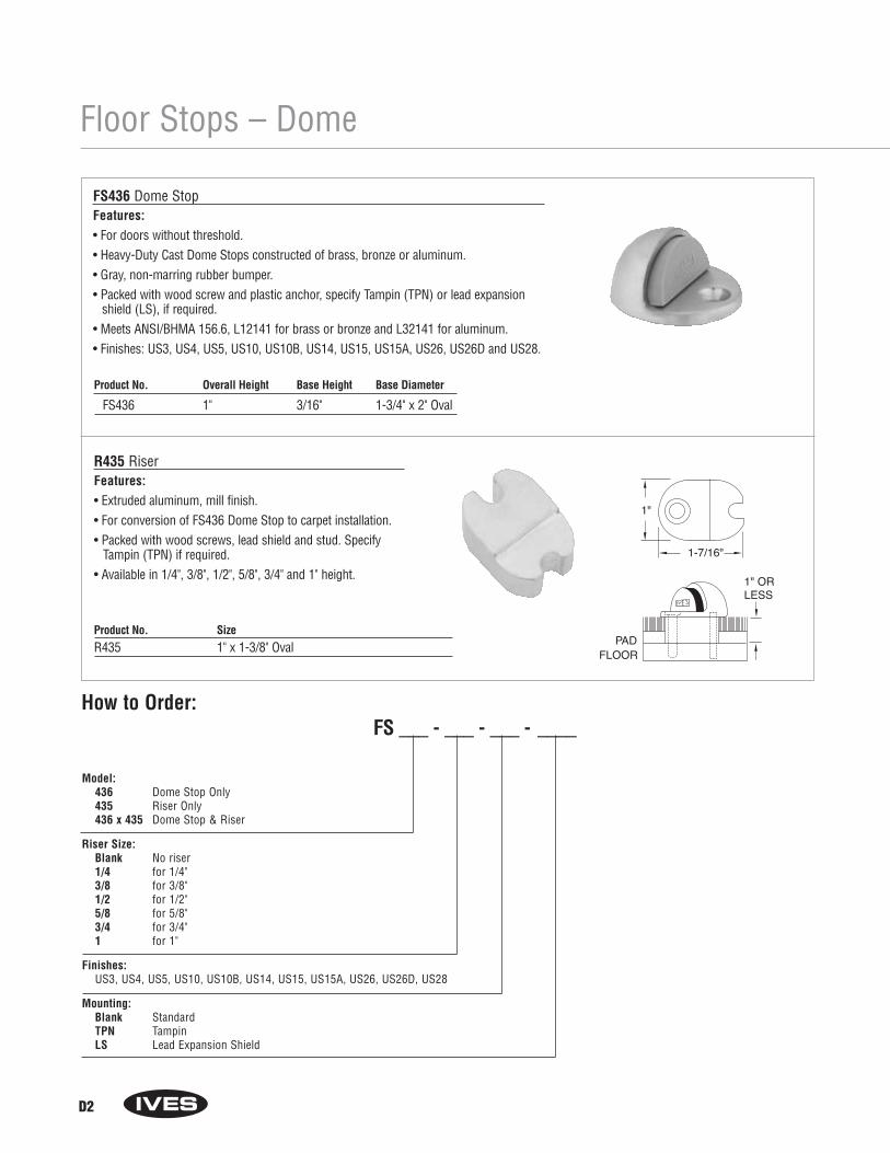
Floor Stops – Dome
D2
FS436 Dome StopFeatures:• For doors without threshold.• Heavy-Duty Cast Dome Stops constructed of brass, bronze or aluminum.• Gray, non-marring rubber bumper.• Packed with wood screw and plastic anchor, specify Tampin (TPN) or lead expansion
shield (LS), if required.• Meets ANSI/BHMA 156.6, L12141 for brass or bronze and L32141 for aluminum.• Finishes: US3, US4, US5, US10, US10B, US14, US15, US15A, US26, US26D and US28.
R435 RiserFeatures:• Extruded aluminum, mill finish.• For conversion of FS436 Dome Stop to carpet installation.• Packed with wood screws, lead shield and stud. Specify
Tampin (TPN) if required.• Available in 1/4", 3/8", 1/2", 5/8", 3/4" and 1" height.
Product No. SizeR435 1" x 1-3/8" Oval
Product No. Overall Height Base Height Base Diameter
FS436 1" 3/16" 1-3/4" x 2" Oval
PADFLOOR
1" ORLESS
1"
1-7/16"
Model:436 Dome Stop Only435 Riser Only436 x 435 Dome Stop & Riser
Riser Size:Blank No riser1/4 for 1/4"3/8 for 3/8"1/2 for 1/2"5/8 for 5/8"3/4 for 3/4"1 for 1"
Finishes:US3, US4, US5, US10, US10B, US14, US15, US15A, US26, US26D, US28
Mounting:Blank StandardTPN TampinLS Lead Expansion Shield
How to Order:FS ___ - ___ - ___ - ____

D3
Floor Stops – Dome
FS438 Dome StopFeatures:• For doors with threshold or undercut doors.• Heavy-Duty Cast Dome Stops constructed of brass, bronze or aluminum.• Gray, non-marring rubber bumper.• Packed with wood screw and plastic anchor, specify Tampin (TPN) or lead expansion
shield (LS), if required.• Meets ANSI/BHMA 156.6, L12141 for brass or bronze and L32141 for aluminum.• Finishes: US3, US4, US5, US10, US10B, US14, US15, US15A, US26, US26D, US28.
R437 RiserFeatures:• Extruded aluminum, mill finish.• For conversion of FS438 Dome Stop to carpet installation.• Packed with wood screws, lead shield and stud. Specify
Tampin (TPN) if required.• Available in 1/4", 3/8", 1/2", 5/8", 3/4" and 1" height.
Product No. SizeR437 1" x 1-3/8" Oval
Product No. Overall Height Base Height Base Diameter
FS438 1-3/8" 9/16" 1-3/4" x 2" Oval
PADFLOOR
1" ORLESS
1"
1-7/16"
Model:438 Dome Stop Only437 Riser Only438 x 437 Dome Stop & Riser
Riser Size:Blank No riser1/4 for 1/4"3/8 for 3/8"1/2 for 1/2"5/8 for 5/8"3/4 for 3/4"1 for 1"
Finishes:US3, US4, US5, US10, US10B, US14, US15, US15A, US26, US26D, US28
Mounting:Blank StandardTPN TampinLS Lead Expansion Shield
How to Order:FS ___ - ___ - ___ - ____
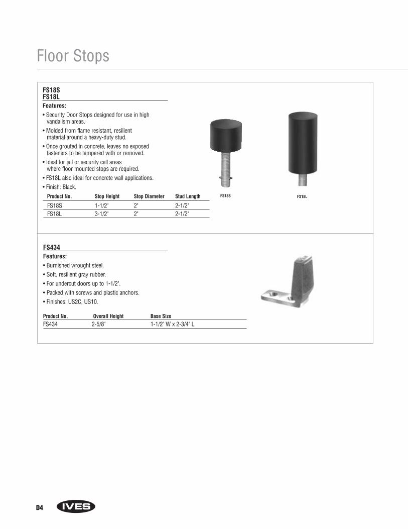
D4
Floor Stops
FS18SFS18LFeatures:• Security Door Stops designed for use in high
vandalism areas.• Molded from flame resistant, resilient
material around a heavy-duty stud.• Once grouted in concrete, leaves no exposed
fasteners to be tampered with or removed.• Ideal for jail or security cell areas
where floor mounted stops are required.• FS18L also ideal for concrete wall applications.• Finish: Black.
FS434Features:• Burnished wrought steel.• Soft, resilient gray rubber.• For undercut doors up to 1-1/2".• Packed with screws and plastic anchors.• Finishes: US2C, US10.
FS18S FS18L
Product No. Overall Height Base SizeFS434 2-5/8" 1-1/2" W x 2-3/4" L
Product No. Stop Height Stop Diameter Stud Length
FS18S 1-1/2" 2" 2-1/2"FS18L 3-1/2" 2" 2-1/2"
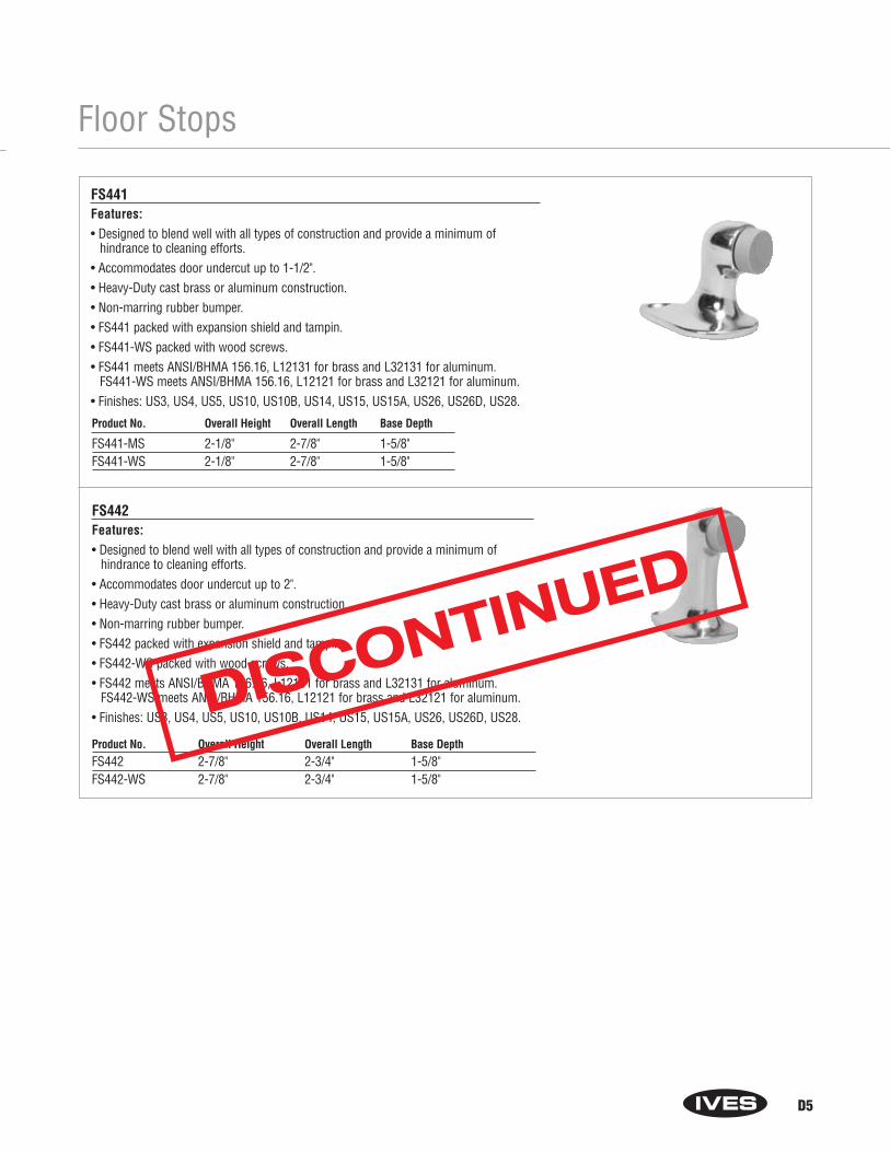
Floor Stops
D5
FS441Features:• Designed to blend well with all types of construction and provide a minimum of
hindrance to cleaning efforts.• Accommodates door undercut up to 1-1/2".• Heavy-Duty cast brass or aluminum construction.• Non-marring rubber bumper.• FS441 packed with expansion shield and tampin.• FS441-WS packed with wood screws.• FS441 meets ANSI/BHMA 156.16, L12131 for brass and L32131 for aluminum.
FS441-WS meets ANSI/BHMA 156.16, L12121 for brass and L32121 for aluminum.• Finishes: US3, US4, US5, US10, US10B, US14, US15, US15A, US26, US26D, US28.
FS442Features:• Designed to blend well with all types of construction and provide a minimum of
hindrance to cleaning efforts.• Accommodates door undercut up to 2".• Heavy-Duty cast brass or aluminum construction.• Non-marring rubber bumper.• FS442 packed with expansion shield and tampin.• FS442-WS packed with wood screws.• FS442 meets ANSI/BHMA 156.16, L12131 for brass and L32131 for aluminum.
FS442-WS meets ANSI/BHMA 156.16, L12121 for brass and L32121 for aluminum.• Finishes: US3, US4, US5, US10, US10B, US14, US15, US15A, US26, US26D, US28.
Product No. Overall Height Overall Length Base DepthFS442 2-7/8" 2-3/4" 1-5/8"FS442-WS 2-7/8" 2-3/4" 1-5/8"
Product No. Overall Height Overall Length Base Depth
FS441-MS 2-1/8" 2-7/8" 1-5/8"FS441-WS 2-1/8" 2-7/8" 1-5/8"
DISCONTINUED
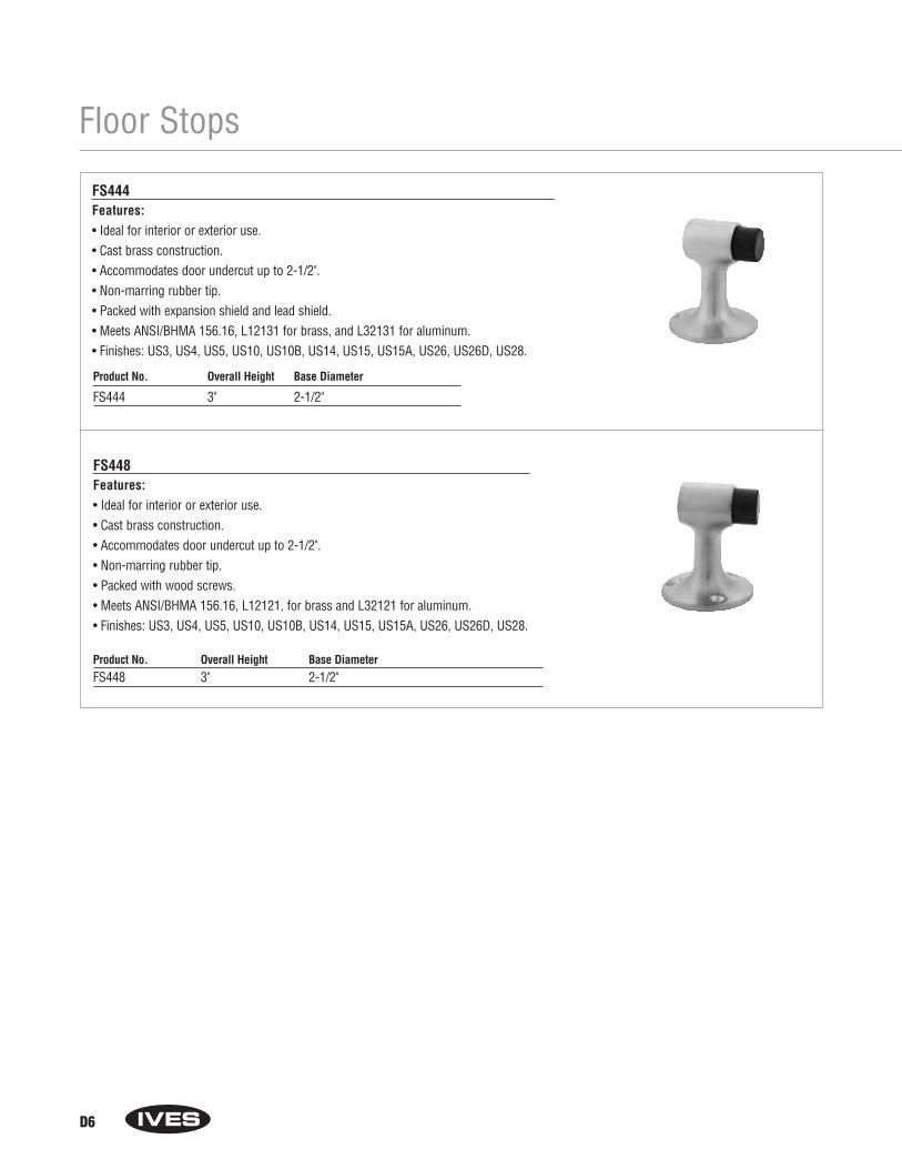
Floor Stops
D6
FS444Features:• Ideal for interior or exterior use.• Cast brass construction.• Accommodates door undercut up to 2-1/2".• Non-marring rubber tip.• Packed with expansion shield and lead shield.• Meets ANSI/BHMA 156.16, L12131 for brass, and L32131 for aluminum.• Finishes: US3, US4, US5, US10, US10B, US14, US15, US15A, US26, US26D, US28.
FS448Features:• Ideal for interior or exterior use.• Cast brass construction.• Accommodates door undercut up to 2-1/2".• Non-marring rubber tip.• Packed with wood screws.• Meets ANSI/BHMA 156.16, L12121, for brass and L32121 for aluminum.• Finishes: US3, US4, US5, US10, US10B, US14, US15, US15A, US26, US26D, US28.
Product No. Overall Height Base DiameterFS448 3" 2-1/2"
Product No. Overall Height Base Diameter
FS444 3" 2-1/2"
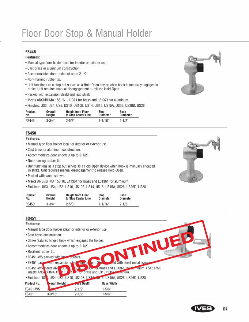
Floor Door Stop & Manual Holder
D7
FS446Features:• Manual type floor holder ideal for interior or exterior use.• Cast brass or aluminum construction.• Accommodates door undercut up to 2-1/2".• Non-marring rubber tip.• Unit functions as a stop but serves as a Hold-Open device when hook is manually engaged in
strike. Unit requires manual disengagement to release Hold-Open.• Packed with expansion shield and lead shield.• Meets ANSI/BHMA 156.16, L11371 for brass and L31371 for aluminum.• Finishes: US3, US4, US5, US10, US10B, US14, US15, US15A, US26, US26D, US28.
FS450Features:• Manual type floor holder ideal for interior or exterior use.• Cast brass or aluminum construction.• Accommodates door undercut up to 2-1/2".• Non-marring rubber tip.• Unit functions as a stop but serves as a Hold-Open device when hook is manually engaged
in strike. Unit requires manual disengagement to release Hold-Open.• Packed with wood screws.• Meets ANSI/BHMA 156.16, L11361 for brass and L31361 for aluminum.• Finishes: US3, US4, US5, US10, US10B, US14, US15, US15A, US26, US26D, US28.
Product Overall Height from Floor Stop BaseNo. Height to Stop Center Line Diameter Diameter
FS446 3-3/4" 2-5/8" 1-1/16" 2-1/2"
Product Overall Height from Floor Stop BaseNo. Height to Stop Center Line Diameter Diameter
FS450 3-3/4" 2-5/8" 1-1/16" 2-1/2"
FS451Features:• Manual type door holder ideal for interior or exterior use.• Cast brass construction.• Strike features hinged hook which engages the holder.• Accommodates door undercut up to 2-1/2".• Resilient rubber tip.• FS451-WS packed with wood screws.• FS451 packed with expansion shield and tampin. Strike packed with sheet metal screws.• FS451-WS meets ANSI/BHMA 156.16, L11361 for brass and L31361 for aluminum. FS451-WS
meets ANSI/BHMA 156.16, L11371 for brass and L31371 for aluminum.• Finishes: US3, US4, US5, US10, US10B, US14, US15, US15A, US26, US26D, US28.Product No. Overall Height Base Depth Base Width
FS451-WS 3-3/16" 2-1/2" 1-5/8"FS451 3-3/16" 2-1/2" 1-5/8"
DISCONTINUED
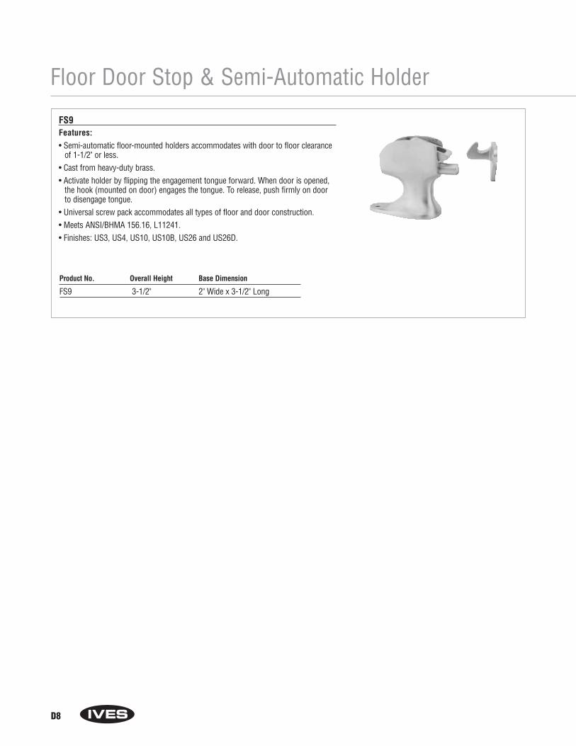
Floor Door Stop & Semi-Automatic Holder
D8
FS9Features:• Semi-automatic floor-mounted holders accommodates with door to floor clearance
of 1-1/2" or less.• Cast from heavy-duty brass.• Activate holder by flipping the engagement tongue forward. When door is opened,
the hook (mounted on door) engages the tongue. To release, push firmly on doorto disengage tongue.
• Universal screw pack accommodates all types of floor and door construction.• Meets ANSI/BHMA 156.16, L11241.• Finishes: US3, US4, US10, US10B, US26 and US26D.
Product No. Overall Height Base Dimension
FS9 3-1/2" 2" Wide x 3-1/2" Long

Floor Door Stop & Automatic Holder
D9
FS40FS41FS42FS43Features:• Automatic door holders ideal for heavy-traffic situations that require a simple,
fool-proof, Hold-Open device.• Forged from brass.• Unit is activated automatically when door is opened. A firm pull on door releases
the mechanism.• Strikes accommodate different door to floor clearances.• Model numbers are determined by strike/door-to-floor clearances.• Holder position on door is adjustable.• Universal screw pack allows for installation in all types of door construction.• Meets ANSI/BHMA 156.16, L11301.• Finishes: US3, US4, US10, US10B, US26, US26D.
Product No. Door to Floor Clearance Holder Dimensions
FS40 1/2" or less 3" Wide x 3-11/16" HighFS41 9/16" to 1-1/16" 3" Wide x 3-11/16" HighFS42 1-1/8" to 1-9/16" 3" Wide x 3-11/16" HighFS43 1-5/8" to 2-1/16" 3" Wide x 3-11/16" High
Optional Strike Details
FS41 FS42
FS40
FS43
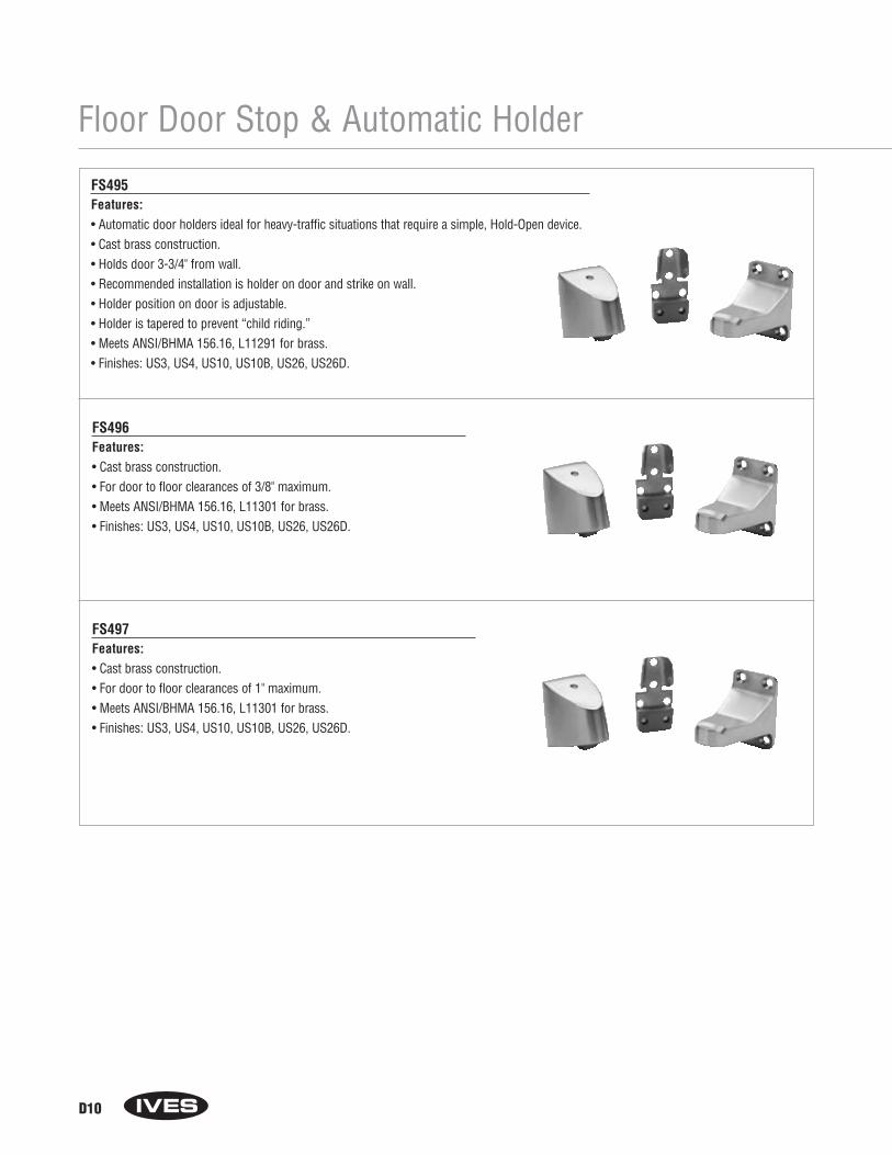
Floor Door Stop & Automatic Holder
D10
FS495Features:• Automatic door holders ideal for heavy-traffic situations that require a simple, Hold-Open device.• Cast brass construction.• Holds door 3-3/4" from wall.• Recommended installation is holder on door and strike on wall.• Holder position on door is adjustable.• Holder is tapered to prevent “child riding.”• Meets ANSI/BHMA 156.16, L11291 for brass.• Finishes: US3, US4, US10, US10B, US26, US26D.
FS496Features:• Cast brass construction.• For door to floor clearances of 3/8" maximum.• Meets ANSI/BHMA 156.16, L11301 for brass.• Finishes: US3, US4, US10, US10B, US26, US26D.
FS497Features:• Cast brass construction.• For door to floor clearances of 1" maximum.• Meets ANSI/BHMA 156.16, L11301 for brass.• Finishes: US3, US4, US10, US10B, US26, US26D.
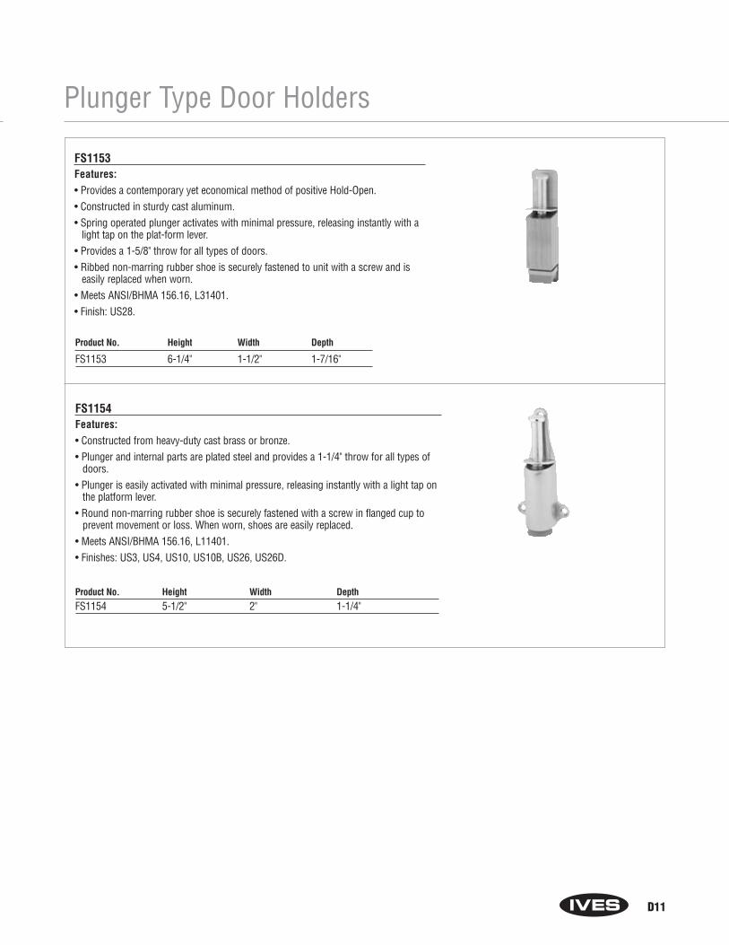
Plunger Type Door Holders
D11
FS1153Features:• Provides a contemporary yet economical method of positive Hold-Open.• Constructed in sturdy cast aluminum.• Spring operated plunger activates with minimal pressure, releasing instantly with a
light tap on the plat-form lever.• Provides a 1-5/8" throw for all types of doors.• Ribbed non-marring rubber shoe is securely fastened to unit with a screw and is
easily replaced when worn.• Meets ANSI/BHMA 156.16, L31401.• Finish: US28.
FS1154Features:• Constructed from heavy-duty cast brass or bronze.• Plunger and internal parts are plated steel and provides a 1-1/4" throw for all types of
doors.• Plunger is easily activated with minimal pressure, releasing instantly with a light tap on
the platform lever.• Round non-marring rubber shoe is securely fastened with a screw in flanged cup to
prevent movement or loss. When worn, shoes are easily replaced.• Meets ANSI/BHMA 156.16, L11401.• Finishes: US3, US4, US10, US10B, US26, US26D.
Product No. Height Width DepthFS1154 5-1/2" 2" 1-1/4"
Product No. Height Width Depth
FS1153 6-1/4" 1-1/2" 1-7/16"
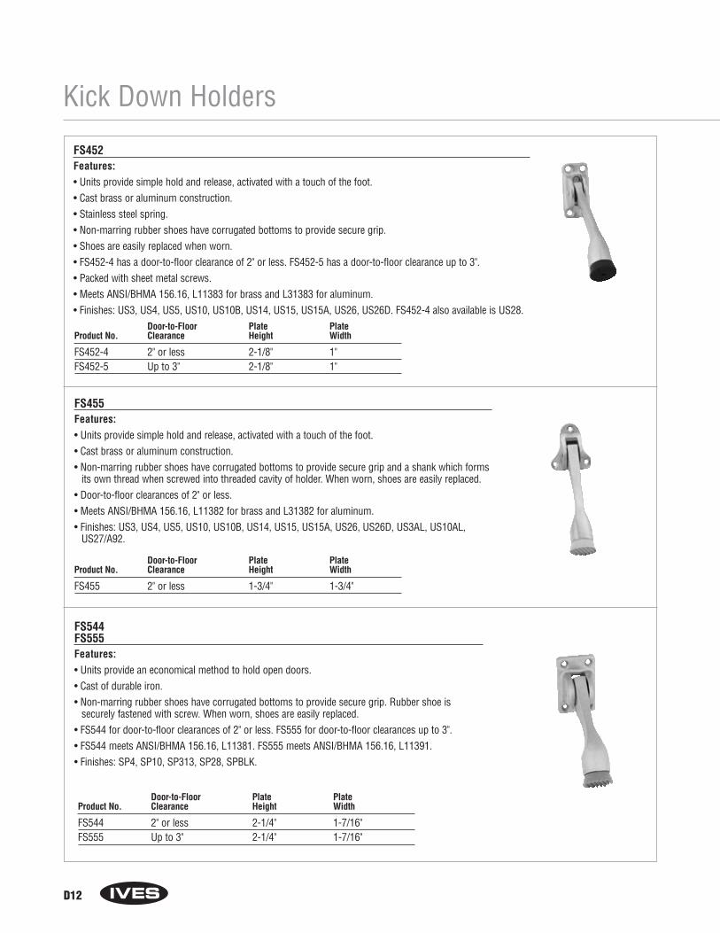
Kick Down Holders
D12
FS452Features:• Units provide simple hold and release, activated with a touch of the foot.• Cast brass or aluminum construction.• Stainless steel spring.• Non-marring rubber shoes have corrugated bottoms to provide secure grip.• Shoes are easily replaced when worn.• FS452-4 has a door-to-floor clearance of 2" or less. FS452-5 has a door-to-floor clearance up to 3".• Packed with sheet metal screws.• Meets ANSI/BHMA 156.16, L11383 for brass and L31383 for aluminum.• Finishes: US3, US4, US5, US10, US10B, US14, US15, US15A, US26, US26D. FS452-4 also available is US28.
FS455Features:• Units provide simple hold and release, activated with a touch of the foot.• Cast brass or aluminum construction.• Non-marring rubber shoes have corrugated bottoms to provide secure grip and a shank which forms
its own thread when screwed into threaded cavity of holder. When worn, shoes are easily replaced.• Door-to-floor clearances of 2" or less.• Meets ANSI/BHMA 156.16, L11382 for brass and L31382 for aluminum.• Finishes: US3, US4, US5, US10, US10B, US14, US15, US15A, US26, US26D, US3AL, US10AL,
US27/A92.
Door-to-Floor Plate PlateProduct No. Clearance Height Width
FS452-4 2" or less 2-1/8" 1"FS452-5 Up to 3" 2-1/8" 1"
Door-to-Floor Plate PlateProduct No. Clearance Height Width
FS455 2" or less 1-3/4" 1-3/4"
Door-to-Floor Plate PlateProduct No. Clearance Height Width
FS544 2" or less 2-1/4" 1-7/16"FS555 Up to 3" 2-1/4" 1-7/16"
FS544FS555Features:• Units provide an economical method to hold open doors.• Cast of durable iron.• Non-marring rubber shoes have corrugated bottoms to provide secure grip. Rubber shoe is
securely fastened with screw. When worn, shoes are easily replaced.• FS544 for door-to-floor clearances of 2" or less. FS555 for door-to-floor clearances up to 3".• FS544 meets ANSI/BHMA 156.16, L11381. FS555 meets ANSI/BHMA 156.16, L11391.• Finishes: SP4, SP10, SP313, SP28, SPBLK.
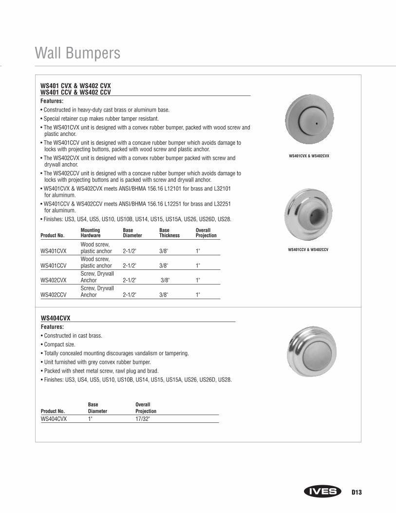
Wall Bumpers
D13
WS401 CVX & WS402 CVXWS401 CCV & WS402 CCVFeatures:• Constructed in heavy-duty cast brass or aluminum base.• Special retainer cup makes rubber tamper resistant.• The WS401CVX unit is designed with a convex rubber bumper, packed with wood screw and
plastic anchor.• The WS401CCV unit is designed with a concave rubber bumper which avoids damage to
locks with projecting buttons, packed with wood screw and plastic anchor.• The WS402CVX unit is designed with a convex rubber bumper packed with screw and
drywall anchor.• The WS402CCV unit is designed with a concave rubber bumper which avoids damage to
locks with projecting buttons and is packed with screw and drywall anchor.• WS401CVX & WS402CVX meets ANSI/BHMA 156.16 L12101 for brass and L32101
for aluminum.• WS401CCV & WS402CCV meets ANSI/BHMA 156.16 L12251 for brass and L32251
for aluminum.• Finishes: US3, US4, US5, US10, US10B, US14, US15, US15A, US26, US26D, US28.
WS404CVXFeatures:• Constructed in cast brass.• Compact size.• Totally concealed mounting discourages vandalism or tampering.• Unit furnished with grey convex rubber bumper.• Packed with sheet metal screw, rawl plug and brad.• Finishes: US3, US4, US5, US10, US10B, US14, US15, US15A, US26, US26D, US28.
Base OverallProduct No. Diameter ProjectionWS404CVX 1" 17/32"
Mounting Base Base OverallProduct No. Hardware Diameter Thickness Projection
Wood screw,WS401CVX plastic anchor 2-1/2" 3/8" 1"
Wood screw,WS401CCV plastic anchor 2-1/2" 3/8" 1"
Screw, DrywallWS402CVX Anchor 2-1/2" 3/8" 1"
Screw, DrywallWS402CCV Anchor 2-1/2" 3/8" 1"
WS401CVX & WS402CVX
WS401CCV & WS402CCV
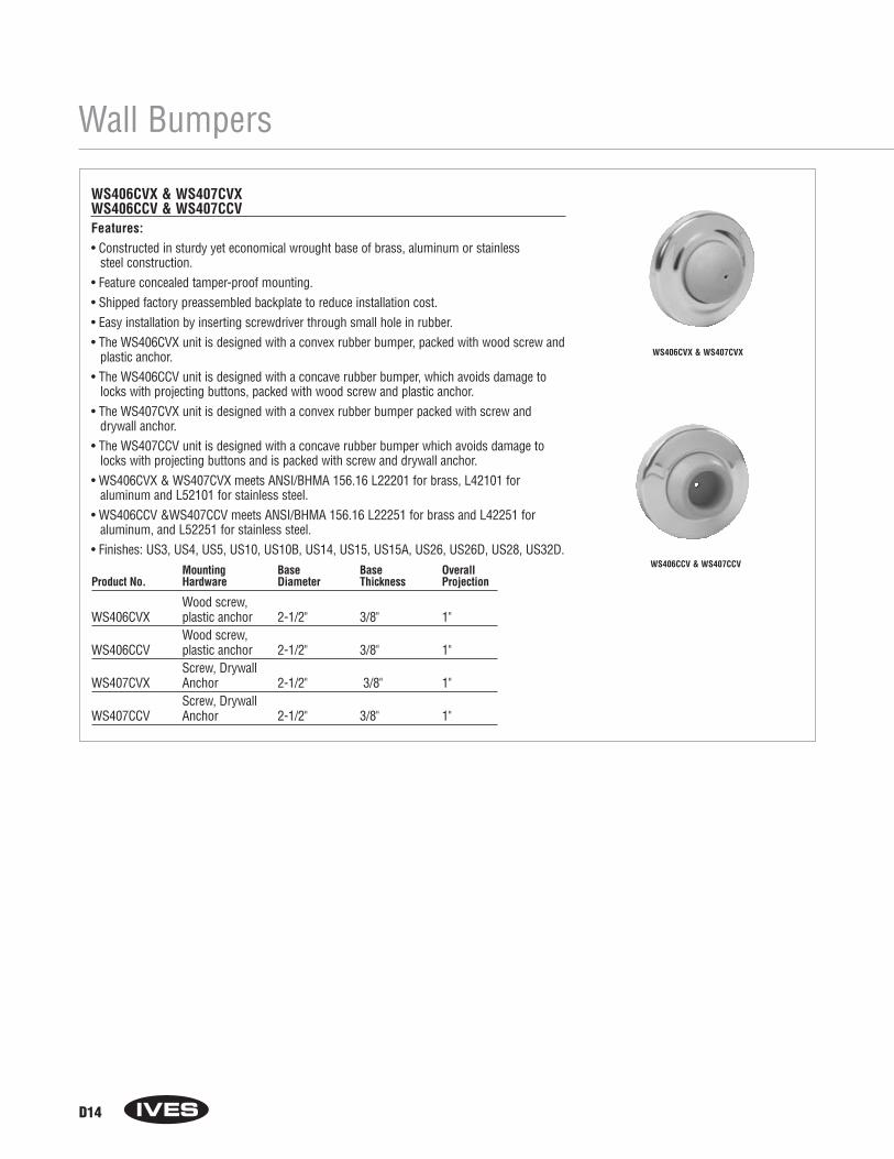
Wall Bumpers
D14
WS406CVX & WS407CVXWS406CCV & WS407CCVFeatures:• Constructed in sturdy yet economical wrought base of brass, aluminum or stainless
steel construction.• Feature concealed tamper-proof mounting.• Shipped factory preassembled backplate to reduce installation cost.• Easy installation by inserting screwdriver through small hole in rubber.• The WS406CVX unit is designed with a convex rubber bumper, packed with wood screw and
plastic anchor.• The WS406CCV unit is designed with a concave rubber bumper, which avoids damage to
locks with projecting buttons, packed with wood screw and plastic anchor.• The WS407CVX unit is designed with a convex rubber bumper packed with screw and
drywall anchor.• The WS407CCV unit is designed with a concave rubber bumper which avoids damage to
locks with projecting buttons and is packed with screw and drywall anchor.• WS406CVX & WS407CVX meets ANSI/BHMA 156.16 L22201 for brass, L42101 for
aluminum and L52101 for stainless steel.• WS406CCV &WS407CCV meets ANSI/BHMA 156.16 L22251 for brass and L42251 for
aluminum, and L52251 for stainless steel.• Finishes: US3, US4, US5, US10, US10B, US14, US15, US15A, US26, US26D, US28, US32D.
Mounting Base Base OverallProduct No. Hardware Diameter Thickness Projection
Wood screw,WS406CVX plastic anchor 2-1/2" 3/8" 1"
Wood screw,WS406CCV plastic anchor 2-1/2" 3/8" 1"
Screw, DrywallWS407CVX Anchor 2-1/2" 3/8" 1"
Screw, DrywallWS407CCV Anchor 2-1/2" 3/8" 1"
WS406CVX & WS407CVX
WS406CCV & WS407CCV
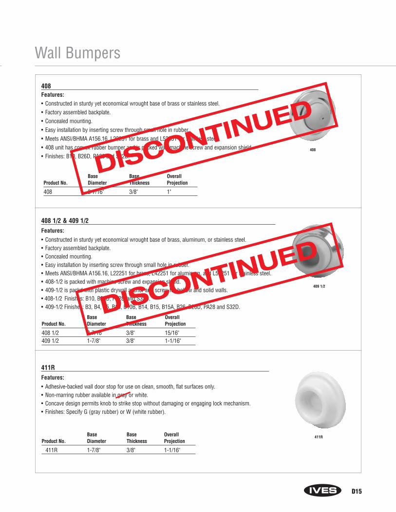
Wall Bumpers
D15
408Features:• Constructed in sturdy yet economical wrought base of brass or stainless steel.• Factory assembled backplate.• Concealed mounting.• Easy installation by inserting screw through small hole in rubber.• Meets ANSI/BHMA A156.16, L22251 for brass and L52251 for stainless steel.• 408 unit has convex rubber bumper and is packed with machine screw and expansion shield. • Finishes: B10, B26D, PA28 and S32D.
Base Base OverallProduct No. Diameter Thickness Projection
408 2-7/16" 3/8" 1"
408
409 1/2
408 1/2 & 409 1/2Features:
• Constructed in sturdy yet economical wrought base of brass, aluminum, or stainless steel.• Factory assembled backplate.• Concealed mounting.• Easy installation by inserting screw through small hole in rubber.• Meets ANSI/BHMA A156.16, L22251 for brass, L42251 for aluminum, and L52251 for stainless steel.• 408-1/2 is packed with machine screw and expansion shield.• 409-1/2 is packd with plastic drywall anchor and screw for hollow and solid walls.• 408-1/2 Finishes: B10, B26D, PA28, and S32D. • 409-1/2 Finishes: B3, B4, B5, B10, B10B, B14, B15, B15A, B26, B26D, PA28 and S32D.
Base Base OverallProduct No. Diameter Thickness Projection
408 1/2 2-7/16" 3/8" 15/16"409 1/2 1-7/8" 3/8" 1-1/16"
411R
411RFeatures:
• Adhesive-backed wall door stop for use on clean, smooth, flat surfaces only.• Non-marring rubber available in gray or white.• Concave design permits knob to strike stop without damaging or engaging lock mechanism.• Finishes: Specify G (gray rubber) or W (white rubber).
Base Base OverallProduct No. Diameter Thickness Projection
411R 1-7/8" 3/8" 1-1/16"
DISCONTINUED
DISCONTINUED

Wall Stops
WS11WS11XFeatures:• Constructed in heavy duty cast brass.• WS11 is furnished with 3 countersunk mounting holes for drywall mounting.• WS11X is furnished with a threaded stud and expansion shield for masonry type mounting.• Hexagon section on unit aids in fastening unit when expansion shield is used.• Rubber bumpers features off-set shoulder and threaded shank that screws into body of unit.• WS11 meets ANSI/BHMA 156.16, L12011 WS11X meets ANSI/BHMA 156.16, L12021.• Finishes: US3, US4, US10, US10B, US26, US26D.
WS33WS33XFeatures:• Constructed in a durable cast brass.• Sturdy rubber bumper with offset shoulder screws into cavity on body to prevent loss or theft.• Sloping design discourages vandalism• WS33 is furnished with 3 mounting holes for drywall mounting.• WS33X is furnished with a threaded stud and expansion shield for masonry type mounting.• Finish: US26D.
Base OverallProduct No. Diameter ProjectionWS11 2" 3-3/4"WS11X 2" 3-3/4"
Base OverallProduct No. Diameter ProjectionWS65 1-5/8" 3-3/4"
Base Base OverallProduct No. Height Width ProjectionWS33 3" 2-1/4" 3-3/4"WS33X 3" 2-1/4" 3-3/4"
WS65Features:• Burnished cast aluminum.• Non-marring rubber bumper.• Packed with sheet metal screws.• Finishes: US3, US10AL, A10B, US27.
D16
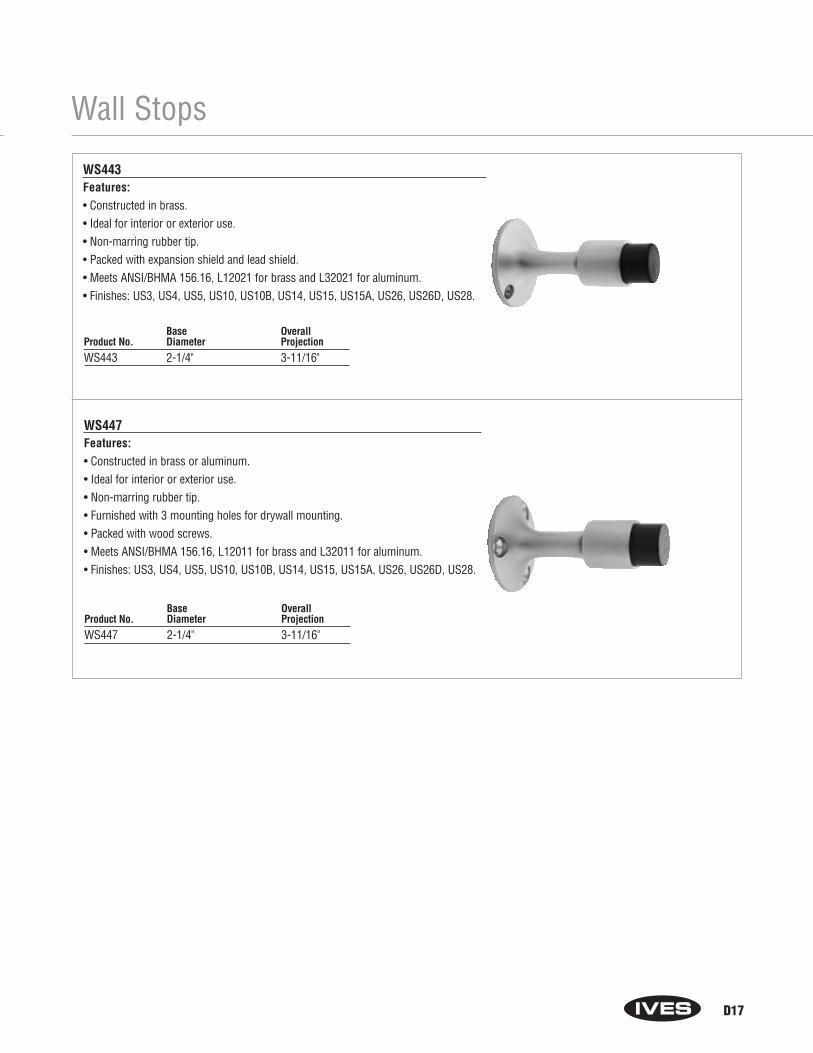
Wall Stops
WS443Features:• Constructed in brass.• Ideal for interior or exterior use.• Non-marring rubber tip.• Packed with expansion shield and lead shield.• Meets ANSI/BHMA 156.16, L12021 for brass and L32021 for aluminum.• Finishes: US3, US4, US5, US10, US10B, US14, US15, US15A, US26, US26D, US28.
WS447Features:• Constructed in brass or aluminum.• Ideal for interior or exterior use.• Non-marring rubber tip.• Furnished with 3 mounting holes for drywall mounting.• Packed with wood screws.• Meets ANSI/BHMA 156.16, L12011 for brass and L32011 for aluminum.• Finishes: US3, US4, US5, US10, US10B, US14, US15, US15A, US26, US26D, US28.
Base OverallProduct No. Diameter ProjectionWS443 2-1/4" 3-11/16"
Base OverallProduct No. Diameter ProjectionWS447 2-1/4" 3-11/16"
D17

Manual Wall Holders
WS20WS20XFeatures:• Constructed in cast brass.• WS20 is furnished 3 countersunk mounting holes for drywall mounting.• WS20X is furnished with threaded stud for masonry type mounting.• Rubber bumpers feature off-set shoulder and threaded shank that screws
into body of holder.• Hinged strike furnished matches body material and finish.• WS20 meets ANSI/BHMA 156.16, L11341 WS20X meets ANSI/BHMA
156.16, L11351• Finishes: US3, US4, US10, US10B, US26, US26D.
WS445Features:• Constructed in cast of brass or aluminum.• Unit functions as a stop but serves as a Hold-Open device when hook is manually
engaged in strike.• Unit requires manual disengagement to release Hold-Open.• Resilient, non-marring rubber tip.• Packed with expansion shield and lead shield.• Meets ANSI/BHMA 156.16, L11351 for brass and L31351 for aluminum.• Finishes: US3, US4, US5, US10, US10B, US14, US15, US15A, US26, US26D, US28.
Base Overall Strike StrikeProduct No. Diameter Projection Height WidthWS20 2-3/8" 4" 2" 1"WS20X 2-3/8" 4" 2" 1"
Product Base Base Engaged Strike Strike StrikeNo. Diameter Projection Projection Height Width ProjectionWS445 2-1/4" 3-11/16" 5-3/4" 1-1/2" 13/16" 13/16"
WS20 Shown
WS449Features:• Constructed in cast of brass or aluminum.• Unit functions as a stop but serves as a Hold-Open device when hook is manually
engaged in strike.• Unit requires manual disengagement to release Hold-Open.• Resilient, non-marring rubber tip.• Packed with wood screws.• Meets ANSI/BHMA 156.16, L11341 for brass and L31341 for aluminum.• Finishes: US3, US4, US5, US10, US10B, US14, US15, US15A, US26, US26D, US28.
Product Base Base Engaged Strike Strike StrikeNo. Diameter Projection Projection Height Width ProjectionWS449 2-1/4" 3-11/16" 5-3/4" 1-1/2" 13/16" 13/16"
D18
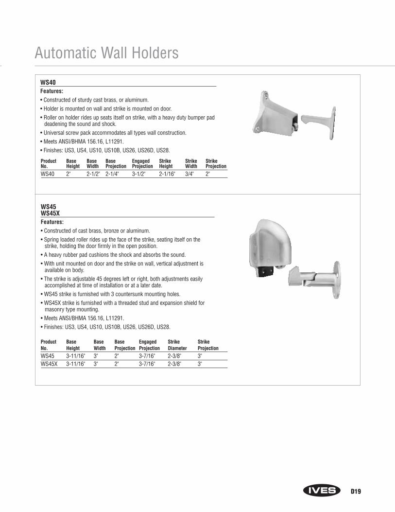
Automatic Wall Holders
WS40Features:• Constructed of sturdy cast brass, or aluminum.• Holder is mounted on wall and strike is mounted on door.• Roller on holder rides up seats itself on strike, with a heavy duty bumper pad
deadening the sound and shock.• Universal screw pack accommodates all types wall construction.• Meets ANSI/BHMA 156.16, L11291.• Finishes: US3, US4, US10, US10B, US26, US26D, US28.
WS45WS45XFeatures:• Constructed of cast brass, bronze or aluminum.• Spring loaded roller rides up the face of the strike, seating itself on the
strike, holding the door firmly in the open position.• A heavy rubber pad cushions the shock and absorbs the sound.• With unit mounted on door and the strike on wall, vertical adjustment is
available on body.• The strike is adjustable 45 degrees left or right, both adjustments easily
accomplished at time of installation or at a later date.• WS45 strike is furnished with 3 countersunk mounting holes.• WS45X strike is furnished with a threaded stud and expansion shield for
masonry type mounting.• Meets ANSI/BHMA 156.16, L11291.• Finishes: US3, US4, US10, US10B, US26, US26D, US28.
Product Base Base Base Engaged Strike Strike StrikeNo. Height Width Projection Projection Height Width ProjectionWS40 2" 2-1/2" 2-1/4" 3-1/2" 2-1/16" 3/4" 2"
Product Base Base Base Engaged Strike StrikeNo. Height Width Projection Projection Diameter ProjectionWS45 3-11/16" 3" 2" 3-7/16" 2-3/8" 3"WS45X 3-11/16" 3" 2" 3-7/16" 2-3/8" 3"
D19

Roller Bumpers
A
B
A
A
RB470 RB471
RB471
RB470RB471RB472Features:• Constructed in heavy-duty cast brass.• RB470 used where two doors open against each other to prevent damage
to the doors or hardware.• RB471 and RB472 are ideal for use in situations where doors meet each
other at approximate right angles (back to back).• RB470 meets ANSI/BHMA 156.16, L12212 RB471 meets ANSI/BHMA
156.16, L12192 RB472 meets ANSI/BHMA 156.16, L12202.• Finishes: US3, US4, US5, US10, US10B, US14, US15, US15A, US26,
US26D.
Base Arm OverallProduct No. Size Offset (B) Length (A)RB470 1-11/16" x 2-1/4" 2-3/4" 5"RB471 2" Dia. –– 4-1/2"RB472 2" Dia. — 6"
D20
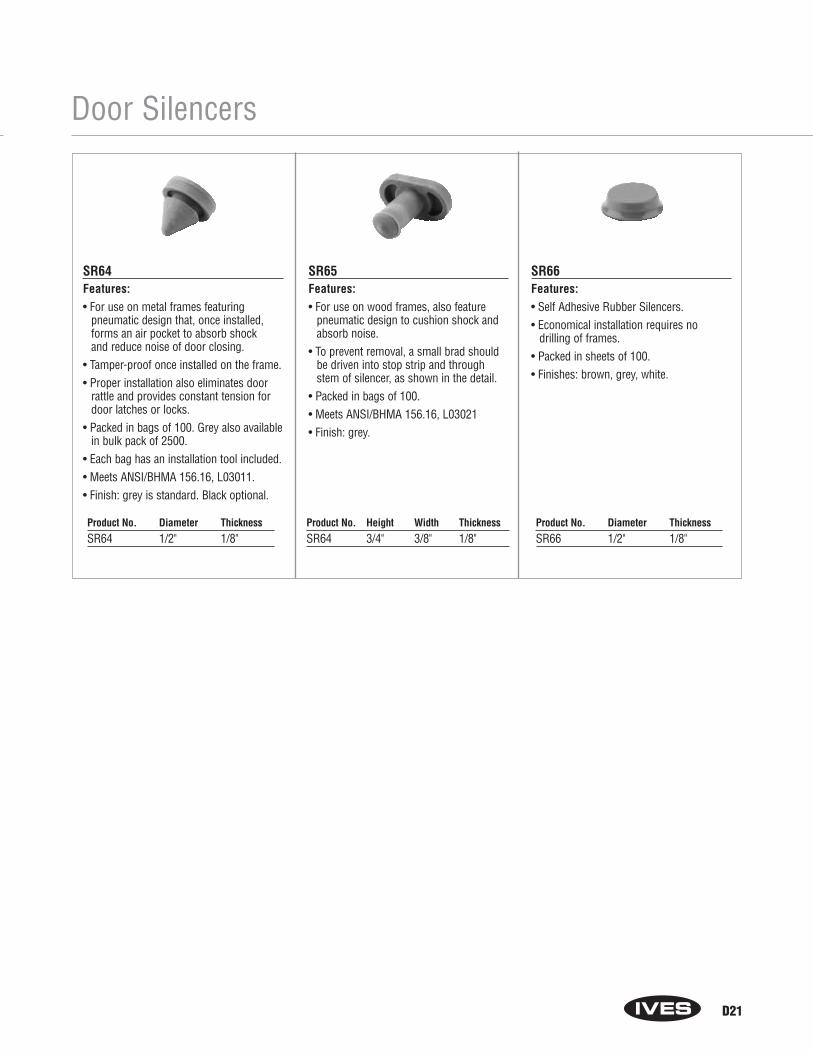
Door Silencers
SR64Features:• For use on metal frames featuring
pneumatic design that, once installed,forms an air pocket to absorb shock and reduce noise of door closing.
• Tamper-proof once installed on the frame.• Proper installation also eliminates door
rattle and provides constant tension fordoor latches or locks.
• Packed in bags of 100. Grey also availablein bulk pack of 2500.
• Each bag has an installation tool included.• Meets ANSI/BHMA 156.16, L03011.• Finish: grey is standard. Black optional.
SR65Features:• For use on wood frames, also feature
pneumatic design to cushion shock andabsorb noise.
• To prevent removal, a small brad shouldbe driven into stop strip and throughstem of silencer, as shown in the detail.
• Packed in bags of 100.• Meets ANSI/BHMA 156.16, L03021• Finish: grey.
SR66Features:• Self Adhesive Rubber Silencers.• Economical installation requires no
drilling of frames.• Packed in sheets of 100.• Finishes: brown, grey, white.
Product No. Diameter ThicknessSR64 1/2" 1/8"
Product No. Height Width ThicknessSR64 3/4" 3/8" 1/8"
Product No. Diameter ThicknessSR66 1/2" 1/8"
D21

Residential Door Stops
D22
061
060
060 and 061 Flexible Door StopsFeatures:• Utilizes heavy gauge spring to maintain rigid protections.• Simple to install - only a screwdriver required.• Rubber tip is replaceable.• Made from burnished wrought steel.• Meets design requirements of ANSI/BHMA A156.16.• Packed disassembled for quick installation.• Finishes: F3, F5, F10, F10B, F14, F26, F26D.
Product Number Projection
060 3"061 4"
60
61
60, 61 and 62 Base Door StopsFeatures:• Available in three sizes to accommodate varying areas of installation and door
trim dimensions.• Rubber tip is replaceable.60 Base Door Stop• Projection: 3-3/4".• Made from solid brass or aluminum. • Finishes: B3 (B-605), B4, B5, B10, B10B (B-613), B14, B15 (B-619), B15A
(B-620), B26 (B-625), B26D, A3, A4, A5, A10, A10B, A14, A26, A92.61 Base Door Stop • Projection: 3-1/8" on brass units. 3-3/16" on aluminum units.• Made from solid brass, aluminum, or epoxy colored aluminum. • Finishes: B3 (B-605), B4, B5, B10, B10B (B-613), B14, B15 (B-619), B15A
(B-620), B26 (B-625), B26D, A3, A4, A5, A10, A10B, A14, A26, A92, A-A(Almond Epoxy Coated), A-W (White Epoxy Coated), A-BLK (Black EpoxyCoated).
62 Base Door Stop • Projection: 4-1/2".• Made from solid brass or aluminum. • Finishes: B3 (B-605), B4, B5, B10, B10B (B-613), B14, B15 (B-619), B15A
(B-620), B26 (B-625), B26D, A3, A4, A5, A10, A10B, A14, A26, A92.
062 Base Door StopFeatures:• Base Door Stop features one-piece styling. • Designed with a flat surface to accommodate wrench or pliers when
installing.• Rubber tip is replaceable.• Made from solid brass or aluminum.• Meets ANSI/BHMA A156.16.• Finishes: B3 (B-605), B4, B5, B10, B10B (B-613), B14, B15 (B-619), B15A
(B-620), B26 (B-625), B26D, A3, A4, A5, A10, A10B, A14, A26, A92.
Product Number Projection
062 2-1/2"
DISCONTINUED
DISCONTINUED
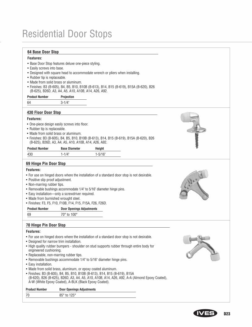
Residential Door Stops
D23
64 Base Door StopFeatures:• Base Door Stop features deluxe one-piece styling. • Easily screws into base.• Designed with square head to accommodate wrench or pliers when installing.• Rubber tip is replaceable.• Made from solid brass or aluminum.• Finishes: B3 (B-605), B4, B5, B10, B10B (B-613), B14, B15 (B-619), B15A (B-620), B26
(B-625), B26D, A3, A4, A5, A10, A10B, A14, A26, A92.Product Number Projection
64 3-1/4"
Product Number Base Diameter Height
430 1-1/4" 1-5/16"
430 Floor Door StopFeatures:• One-piece design easily screws into floor.• Rubber tip is replaceable.• Made from solid brass or aluminum.• Finishes: B3 (B-605), B4, B5, B10, B10B (B-613), B14, B15 (B-619), B15A (B-620), B26
(B-625), B26D, A3, A4, A5, A10, A10B, A14, A26, A92.
69 Hinge Pin Door StopFeatures:• For use on hinged doors where the installation of a standard door stop is not desirable.• Positive slip proof adjustment.• Non-marring rubber tips.• Removable bushings accommodate 1/4" to 5/16" diameter hinge pins.• Easy installation—only a screwdriver required.• Made from burnished wrought steel.• Finishes: F3, F5, F10, F10B, F14, F15, F15A, F26, F26D.Product Number Door Openings Adjustments
69 70° to 100°
Product Number Door Openings Adjustments
70 85° to 125°
70 Hinge Pin Door StopFeatures:• For use on hinged doors where the installation of a standard door stop is not desirable.• Designed for narrow trim installation.• High quality rubber bumpers - shoulder on stud supports rubber through entire body for
engineered cushioning.• Replaceable, non-marring rubber tips.• Removable bushings accommodate 1/4" to 5/16" diameter hinge pins.• Easy installation.• Made from solid brass, aluminum, or epoxy coated aluminum.• Finishes: B3 (B-605), B4, B5, B10, B10B (B-613), B14, B15 (B-619), B15A
(B-620), B26 (B-625), B26D, A3, A4, A5, A10, A10B, A14, A26, A92, A-A (Almond Epoxy Coated),A-W (White Epoxy Coated), A-BLK (Black Epoxy Coated).

Notes
D24
Section ESurface Bolts,
Dutch Door Bolts andDoor Guards

E1
Surface Bolts
SB1600• Standard Surface Bolt has 1" throw for maximum security.• Ideal for all types of doors.• Fully concealed mounting prevents vandalism.• Available in locking version. Unit locks in both the up and down
position. Locking Bolts are furnished with 2 keys in 4 keying variations.• Units packed with wood and machine screws to meet most field conditions.• Units available with either a universal top strike (T) or a flat bottom strike (B).• 1630 Series is constructed of heavy duty steel.• 1640 Series is constructed of brass.• 1630 Series is UL listed up to 3 hours when used on the inactive door of a
pair up to 8' in height.• 1630 meets ANSI/BHMA A156.16, L84161.• 1640 meets ANSI/BHMA A156.16, L24161.• Finishes: 1630 – US2G, US10B, US26D
1640 – US3, US10B, US26D• Optional sex bolts available.
Dimensions:
Body: 8" Long x 7/8" Wide x 3/4" Thick, Overall Knob or Lock Housing Projection: 1-1/2"Top Strike: 1-1/4" Wide x 7/8" Tall x 15/16" DeepBottom Strike: 3" Long x 1" Wide x 1/8" Thick
Model: 30 Steel40 Brass
Strike:T Universal Top StrikeB Flat Bottom StrikeTB Both Strikes, 1630 only
Type: Blank Standard BoltL Locking Bolt
Key Code: Locking only (1289, 1360, 1390, 1395)
Finishes: 1630 US2G, US10B, US26D, 1640 US3, US10B, US26D
How to Order:SB16 _____ _____ _____ - _____ - _____
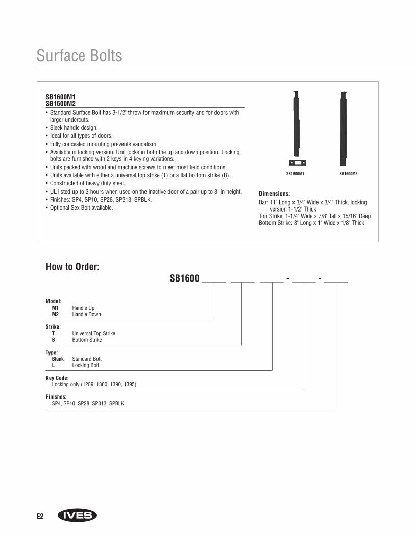
E2
Surface Bolts
SB1600M1SB1600M2• Standard Surface Bolt has 3-1/2" throw for maximum security and for doors with
larger undercuts.• Sleek handle design.• Ideal for all types of doors.• Fully concealed mounting prevents vandalism.• Available in locking version. Unit locks in both the up and down position. Locking
bolts are furnished with 2 keys in 4 keying variations.• Units packed with wood and machine screws to meet most field conditions.• Units available with either a universal top strike (T) or a flat bottom strike (B).• Constructed of heavy duty steel.• UL listed up to 3 hours when used on the inactive door of a pair up to 8' in height.• Finishes: SP4, SP10, SP28, SP313, SPBLK.• Optional Sex Bolt available.
Dimensions:Bar: 11" Long x 3/4" Wide x 3/4" Thick, locking
version 1-1/2" ThickTop Strike: 1-1/4" Wide x 7/8" Tall x 15/16" DeepBottom Strike: 3" Long x 1" Wide x 1/8" Thick
Model: M1 Handle UpM2 Handle Down
Strike: T Universal Top StrikeB Bottom Strike
Type: Blank Standard BoltL Locking Bolt
Key Code: Locking only (1289, 1360, 1390, 1395)
Finishes:SP4, SP10, SP28, SP313, SPBLK
How to Order:SB1600 _____ _____ _____ - _____ - _____
SB1600M1 SB1600M2

E3
Surface Bolts
SB360Features:• Surface Bolt has 1-1/4" throw for maximum security.• Jimmy-resistant design, bolt locks automatically when thrown, can be released only
be pressing knob toward door while retracting.• Ideal for all types of doors.• Available in 12" or 24" lengths.• Unit locks in both the up and down position.• Accepts padlock (not furnished) with maximum 3/8" diameter shackle, minimum
1-3/4" shackle opening height.• Units packed with one-way screws for added security. Standard screws also supplied.• Units available with either a universal top strike (T) or a flat bottom strike (B).• Constructed of heavy duty steel.• 12" Bolt is UL listed up to 3 hours when used on the inactive door of a pair up to
10' in height.• Meets ANSI/BHMA A 156.16.• Finish: US2C• Optional Sex Bolts available.• Optional Mortise Strike available.
Dimensions:
Bar: 3/4" Wide x 3/4" ThickOverall Width: 2-1/32"Overall Projection: 2-1/16"Top Strike: 1-1/2" x 1-1/2" Angle, 3/16" ThickOptional Mortise Strike: 3-1/2" Long x 1-5/8"
Wide x 1/8" Thick
Length: 12 For 12" bolt24 For 24" bolt
Strike: T Universal Top Strike (standard)
Finish:US2C
How to Order:SB360 - _____ - _____ - _____
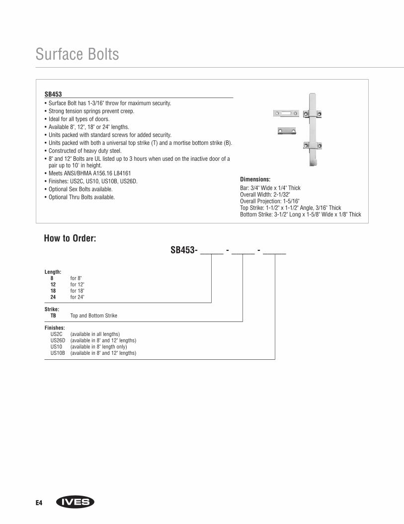
E4
Surface Bolts
SB453• Surface Bolt has 1-3/16" throw for maximum security.• Strong tension springs prevent creep.• Ideal for all types of doors.• Available 8", 12", 18" or 24" lengths.• Units packed with standard screws for added security.• Units packed with both a universal top strike (T) and a mortise bottom strike (B).• Constructed of heavy duty steel.• 8" and 12" Bolts are UL listed up to 3 hours when used on the inactive door of a
pair up to 10' in height.• Meets ANSI/BHMA A156.16 L84161• Finishes: US2C, US10, US10B, US26D.• Optional Sex Bolts available.• Optional Thru Bolts available.
Dimensions:Bar: 3/4" Wide x 1/4" ThickOverall Width: 2-1/32"Overall Projection: 1-5/16"Top Strike: 1-1/2" x 1-1/2" Angle, 3/16" ThickBottom Strike: 3-1/2" Long x 1-5/8" Wide x 1/8" Thick
Length: 8 for 8"12 for 12"18 for 18"24 for 24"
Strike: TB Top and Bottom Strike
Finishes: US2C (available in all lengths)US26D (available in 8" and 12" lengths)US10 (available in 8" length only)US10B (available in 8" and 12" lengths)
How to Order:SB453- _____ - _____ - _____

E5
Surface Bolts
SB454• Surface Bolt has 1-3/16" throw for maximum security.• Jimmy-resistant design, bolt locks automatically when thrown, can be
released only by pressing knob toward door while retracting.• Ideal for all types of doors.• Available 5", 8" and 12" lengths.• 8" and 12" units packed with both a universal top strike (T) and a mortise
bottom strike (B). • 5" unit packed with universal top strike (T) only.• Constructed of heavy duty steel.• Bolts are UL listed up to 3 hours when used on the inactive door of a pair
up to 10' in height.• Meets ANSI/BHMA A156.16 L84161• Finishes: US2C, US10, US10B, US26D.• Optional Sex Bolts available.• Optional Thru Bolts available.
Dimensions:Bar: 3/4" Wide x 1/4" ThickOverall Width: 2-1/32"Overall Projection: 1-5/16"Top Strike: 1-1/2" x 11/2" Angle, 3/16" ThickBottom Strike: 3-1/2" Long x 1-5/8" Wide x 1/8" Thick
Length: 5 for 5"8 for 8"12 for 12"
Strike: T Top Strike (available in 5" length only)TB Top and Bottom Strike (available in 8" or 12")
Finishes: US2C, US10, US26D (available in all lengths)US4 (available in 5" lengths only)US10B (available in all lengths)
How to Order:SB454- _____ - _____ - _____
DISCONTINUED

E6
Surface Bolts
SB0454• Surface Bolt has 1-3/16" throw for maximum security.• Jimmy-resistant design, bolt locks automatically when thrown, can be
released only by pressing knob toward door while retracting.• Ideal for all types of doors.• Available 5" and 8" lengths.• Unit locks in both the up and down position.• Accepts padlock (not furnished) with maximum 3/8" diameter shackle,
minimum 1-3/8" shackle opening height.• Units packed with one-way screws for added security. Standard screws
also supplied.• 8" unit packed with both a universal top strike (T) and a mortise bottom
strike (B).• 5" unit packed with universal top strike (T) only.• Constructed of heavy duty steel.• Meets ANSI/BHMA A156.16 L84161• Finishes: US2C, US26D.• Optional Sex Bolts available.• Optional Thru Bolts available.
Dimensions:Bar: 3/4" Wide x 1/4" ThickOverall Width: 2-1/32"Overall Projection: 1-5/16"Top Strike: 1-1/2" x 1-1/2" Angle, 3/16" ThickBottom Strike: 3-1/2" Long x 1-5/8" Wide x 1/8" Thick
Length: 5 for 5"8 for 8"
Strike: T Top Strike (available in 5" length only)TB Top and Bottom Strike (available in 8" length only)
Finishes: US2C, US26D
How to Order:SB0454- _____ - _____ - _____
DISCONTINUED
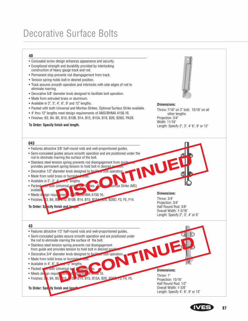
E7
Decorative Surface Bolts
40• Concealed screw design enhances appearance and security.• Exceptional strength and durability provided by interlocking
construction of heavy gauge track and rod.• Permanent stop prevents rod disengagement from track.• Tension spring holds bolt in desired position.• Track assures smooth operation and interlocks with side edges of rod to
eliminate marring.• Decorative 5/8" diameter knob designed to facilitate bolt operation.• Made from extruded brass or aluminum.• Available in 2", 3", 4", 6", 9" and 12" lengths.• Packed with both Universal and Mortise Strikes. Optional Surface Strike available. • 4" thru 12" lengths meet design requirements of ANSI/BHMA A156.16.• Finishes: B3, B4, B5, B10, B10B, B14, B15, B15A, B19, B26, B26D, PA28.
To Order: Specify finish and length.
Dimensions:Throw: 7/16" on 2" bolt; 15/16" on all
other lengthsProjection: 3/4" Width: 11/16"Length: Specify 2", 3", 4" 6", 9" or 12"
043• Features attractive 3/8" half-round rods and well-proportioned guides. • Semi-concealed guides assure smooth operation and are positioned under the
rod to eliminate marring the surface of the bolt.• Stainless steel tension spring prevents rod disengagement from guide and
provides permanent spring tension to hold bolt in desired position.• Decorative 1/2" diameter knob designed to facilitate bolt operation.• Made from solid brass or burnished steel.• Available in 2", 3", 4" and 6" lengths.• Packed with both Universal and Angle Strikes. Optional Mortise Strike (MS)
available. • Meets design requirements of ANSI/BHMA A156.16.• Finishes: B3, B4, B5, B10, B10B, B14, B15, B15A, B26, B26D, F3, F5, F14.
To Order: Specify finish and length.
Dimensions:Throw: 3/4"Projection: 3/4" Half Round Rod: 3/8"Overall Width: 1-3/16"Length: Specify 2", 3", 4" or 6"
43• Features attractive 1/2" half-round rods and well-proportioned guides.• Semi-concealed guides assure smooth operation and are positioned under
the rod to eliminate marring the surface of the bolt.• Stainless steel tension spring prevents rod disengagement
from guide and provides tension to hold bolt in desired position.• Decorative 3/4" diameter knob designed to facilitate bolt operation.• Made from solid brass or burnished steel.• Available in 4", 6", 9" and 12" lengths.• Packed with both Universal and Angle Strikes. • Meets design requirements of ANSI/BHMA A156.16.• Finishes: B3, B4, B5, B10, B10B, B14, B15, B15A, B26, B26D, F3, F4, F5.
To Order: Specify finish and length.
Dimensions:Throw: 1"Projection: 15/16" Half Round Rod: 1/2" Overall Width: 1-3/8"Length: Specify 4", 6", 9" or 12"
DISCONTINUED
DISCONTINUED
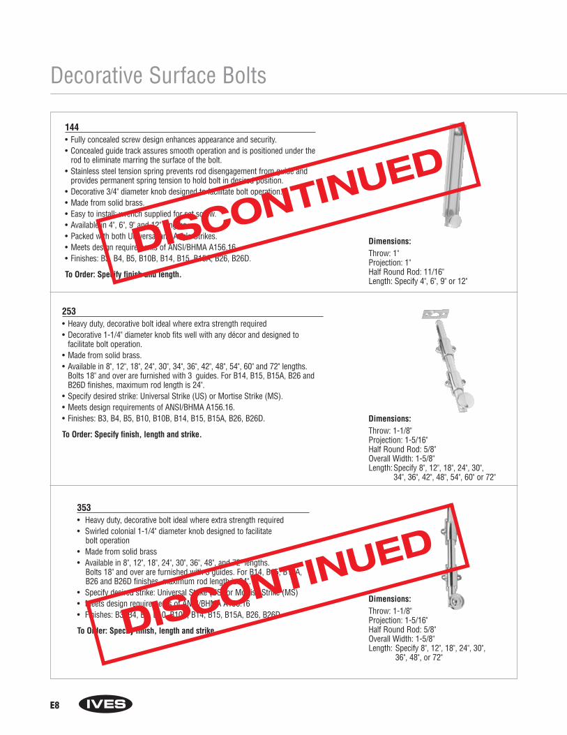
E8
Decorative Surface Bolts
144• Fully concealed screw design enhances appearance and security.• Concealed guide track assures smooth operation and is positioned under the
rod to eliminate marring the surface of the bolt.• Stainless steel tension spring prevents rod disengagement from guide and
provides permanent spring tension to hold bolt in desired position.• Decorative 3/4" diameter knob designed to facilitate bolt operation.• Made from solid brass. • Easy to install; wrench supplied for set screw.• Available in 4", 6", 9" and 12" lengths.• Packed with both Universal and Angle Strikes. • Meets design requirements of ANSI/BHMA A156.16.• Finishes: B3, B4, B5, B10B, B14, B15, B15A, B26, B26D.
To Order: Specify finish and length.
Dimensions:Throw: 1"Projection: 1" Half Round Rod: 11/16" Length: Specify 4", 6", 9" or 12"
253• Heavy duty, decorative bolt ideal where extra strength required• Decorative 1-1/4" diameter knob fits well with any décor and designed to
facilitate bolt operation.• Made from solid brass. • Available in 8", 12", 18", 24", 30", 34", 36", 42", 48", 54", 60" and 72" lengths.
Bolts 18" and over are furnished with 3 guides. For B14, B15, B15A, B26 andB26D finishes, maximum rod length is 24".
• Specify desired strike: Universal Strike (US) or Mortise Strike (MS). • Meets design requirements of ANSI/BHMA A156.16.• Finishes: B3, B4, B5, B10, B10B, B14, B15, B15A, B26, B26D.
To Order: Specify finish, length and strike.
Dimensions:Throw: 1-1/8"Projection: 1-5/16" Half Round Rod: 5/8"Overall Width: 1-5/8" Length:Specify 8", 12", 18", 24", 30",
34", 36", 42", 48", 54", 60" or 72"
353• Heavy duty, decorative bolt ideal where extra strength required• Swirled colonial 1-1/4" diameter knob designed to facilitate
bolt operation• Made from solid brass • Available in 8", 12", 18", 24", 30", 36", 48", and 72" lengths.
Bolts 18" and over are furnished with 3 guides. For B14, B15, B15A, B26 and B26D finishes, maximum rod length is 24".
• Specify desired strike: Universal Strike (US) or Mortise Strike (MS) • Meets design requirements of ANSI/BHMA A156.16• Finishes: B3, B4, B5, B10, B10B, B14, B15, B15A, B26, B26D
To Order: Specify finish, length and strike.
Dimensions:Throw: 1-1/8"Projection: 1-5/16" Half Round Rod: 5/8"Overall Width: 1-5/8" Length: Specify 8", 12", 18", 24", 30",
36", 48", or 72"
DISCONTINUED
DISCONTINUED
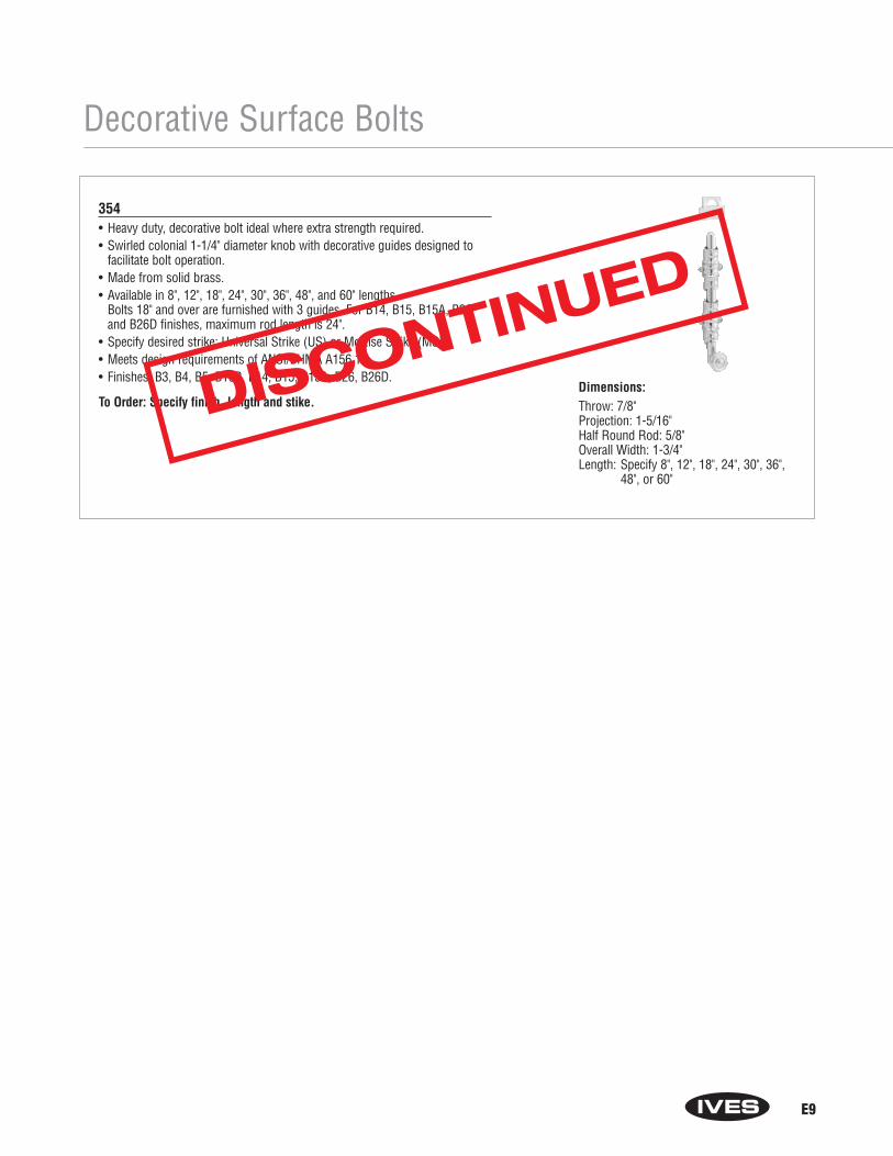
E9
Decorative Surface Bolts
354• Heavy duty, decorative bolt ideal where extra strength required.• Swirled colonial 1-1/4" diameter knob with decorative guides designed to
facilitate bolt operation.• Made from solid brass. • Available in 8", 12", 18", 24", 30", 36", 48", and 60" lengths.
Bolts 18" and over are furnished with 3 guides. For B14, B15, B15A, B26and B26D finishes, maximum rod length is 24".
• Specify desired strike: Universal Strike (US) or Mortise Strike (MS). • Meets design requirements of ANSI/BHMA A156.16.• Finishes: B3, B4, B5, B10B, B14, B15, B15A, B26, B26D.
To Order: Specify finish, length and stike.Dimensions:Throw: 7/8"Projection: 1-5/16" Half Round Rod: 5/8"Overall Width: 1-3/4" Length: Specify 8", 12", 18", 24", 30", 36",
48", or 60"
DISCONTINUED
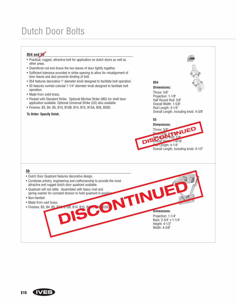
E10
Dutch Door Bolts
054 and 55• Practical, rugged, attractive bolt for application on dutch doors as well as
other areas.• Chamfered rod end draws the two leaves of door tightly together.• Sufficient tolerance provided in strike opening to allow for misalignment of
door leaves and also prevents binding of bolt.• 054 features decorative 1" diameter knob designed to facilitate bolt operation.• 55 features swirled colonial 1-1/4" diameter knob designed to facilitate bolt
operation.• Made from solid brass. • Packed with Standard Strike. Optional Mortise Strike (MS) for shelf door
application available. Optional Universal Strike (US) also available.• Finishes: B3, B4, B5, B10, B10B, B14, B15, B15A, B26, B26D.
To Order: Specify finish.
054Dimensions:Throw: 5/8"Projection: 1-1/8" Half Round Rod: 5/8"Overall Width: 1-5/8"Rod Length: 4-1/4"Overall Length, including knob: 4-3/8"
55Dimensions:Throw: 5/8"Projection: 1-5/16" Half Round Rod: 5/8"Overall Width: 1-9/16"Rod Length: 4-1/4"Overall Length, including knob: 4-1/2"
56• Dutch Door Quadrant features decorative design.• Combines artistry, engineering and craftsmanship to provide the most
attractive and rugged dutch door quadrant available.• Quadrant will not rattle. Assembled with heavy rivet and
spring washer for constant tension to hold quadrant in position.• Non-handed.• Made from cast brass. • Finishes: B3, B4, B5, B10, B10B, B14, B15, B15A, B26, B26D.
Dimensions:Projection: 1-1/4"Base: 2-3/4" x 1-1/4" Height: 4-1/2"Width: 4-3/8"
DISCONTINUED
DISCONTINUED

E11
Security Door Bolts
87• Security Door Bolt is the ultimate in strength, simplicity, and security.• Solid brass bolt is permanently housed in a precision
designed extrusion of solid brass.• Milled slot in bolt housing insures bolt remains locked or
unlocked in spite of vibration.• Non-handed.• Made from solid brass. • Packed with universal, surface, and angle strikes, and recessed head screws.• Finishes: B3, B4, B5, B10, B10B, B15, B15A, B26, B26D.
To Order: Specify finish.
Dimensions:Throw: 5/8"Projection: 15/32"Bolt Diameter: 5/16"Overall Width: 1-1/4"Length: 2-1/4"
DISCONTINUED
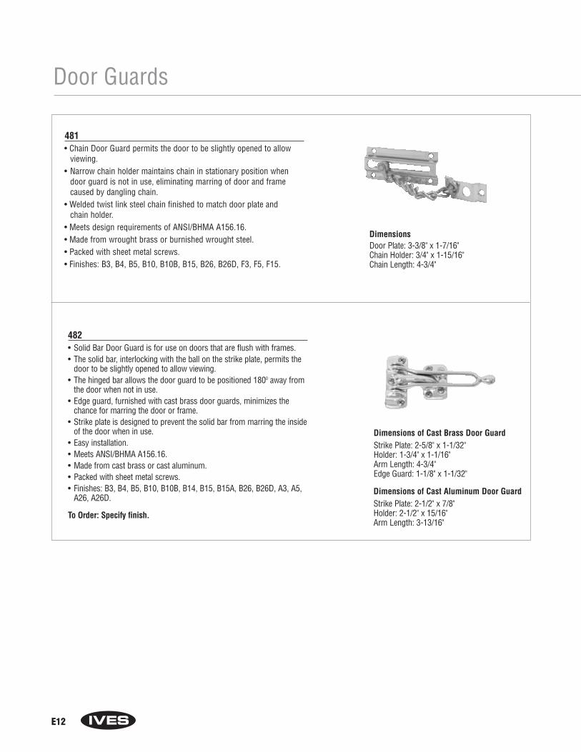
E12
Door Guards
482• Solid Bar Door Guard is for use on doors that are flush with frames.• The solid bar, interlocking with the ball on the strike plate, permits the
door to be slightly opened to allow viewing. • The hinged bar allows the door guard to be positioned 1800 away from
the door when not in use.• Edge guard, furnished with cast brass door guards, minimizes the
chance for marring the door or frame.• Strike plate is designed to prevent the solid bar from marring the inside
of the door when in use.• Easy installation.• Meets ANSI/BHMA A156.16.• Made from cast brass or cast aluminum. • Packed with sheet metal screws.• Finishes: B3, B4, B5, B10, B10B, B14, B15, B15A, B26, B26D, A3, A5,
A26, A26D.
To Order: Specify finish.
Dimensions of Cast Brass Door GuardStrike Plate: 2-5/8" x 1-1/32"Holder: 1-3/4" x 1-1/16"Arm Length: 4-3/4"Edge Guard: 1-1/8" x 1-1/32"
Dimensions of Cast Aluminum Door GuardStrike Plate: 2-1/2" x 7/8"Holder: 2-1/2" x 15/16"Arm Length: 3-13/16"
481• Chain Door Guard permits the door to be slightly opened to allow
viewing.• Narrow chain holder maintains chain in stationary position when
door guard is not in use, eliminating marring of door and framecaused by dangling chain.
• Welded twist link steel chain finished to match door plate and chain holder.
• Meets design requirements of ANSI/BHMA A156.16.• Made from wrought brass or burnished wrought steel. • Packed with sheet metal screws.• Finishes: B3, B4, B5, B10, B10B, B15, B26, B26D, F3, F5, F15.
DimensionsDoor Plate: 3-3/8" x 1-7/16"Chain Holder: 3/4" x 1-15/16"Chain Length: 4-3/4"
Section FExterior Door Hardware
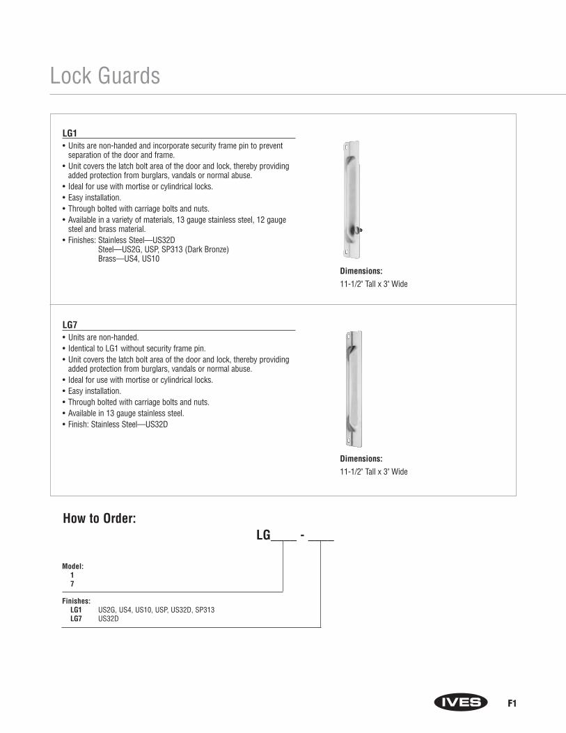
F1
Lock Guards
LG1• Units are non-handed and incorporate security frame pin to prevent
separation of the door and frame.• Unit covers the latch bolt area of the door and lock, thereby providing
added protection from burglars, vandals or normal abuse.• Ideal for use with mortise or cylindrical locks.• Easy installation.• Through bolted with carriage bolts and nuts.• Available in a variety of materials, 13 gauge stainless steel, 12 gauge
steel and brass material.• Finishes: Stainless Steel—US32D
Steel—US2G, USP, SP313 (Dark Bronze)Brass—US4, US10
LG7• Units are non-handed.• Identical to LG1 without security frame pin.• Unit covers the latch bolt area of the door and lock, thereby providing
added protection from burglars, vandals or normal abuse.• Ideal for use with mortise or cylindrical locks.• Easy installation.• Through bolted with carriage bolts and nuts.• Available in 13 gauge stainless steel.• Finish: Stainless Steel—US32D
Model:17
Finishes:LG1 US2G, US4, US10, USP, US32D, SP313LG7 US32D
How to Order:LG____ - ____
Dimensions:
11-1/2" Tall x 3" Wide
Dimensions:
11-1/2" Tall x 3" Wide

F2
Lock Guards
LG10 • Ideally suited for use with rose or escutcheon 2-3/4" wide or less.• For use with Type 86 Mortise and Type 161 Cylinder Locks (ANSI
156.13 Series 1000 and ANSI 156.2 Series 4000).• No exposed fasteners on face of unit.• Unique design provides maximum security, virtually eliminating
the opening between door and frame at the latch point.• Available in 13 Gauge Stainless Steel or 12 Gauge Steel.• Finishes: Stainless Steel—US32D
Steel—USP
LG12 • Narrow design unit for use on rose or escutcheon 3-1/2" or less.• For use with Type 86 Mortise and Type 161 Cylinder Locks
(ANSI 156.13 Series 1000 and ANSI 156.2 Series 4000).• No exposed fasteners on face of unit.• Unique design provides maximum security, virtually eliminating
the opening between door and frame at the latch point.• Available in 13 Gauge Stainless Steel or 12 Gauge Steel • Finishes: Stainless Steel—US32D
Steel—USP
LG10 thru LG12
LG11• Designed for use on aluminum doors with latch-type locks
or doors equipped with electric strikes.• Unit is Handed - Specify left or right hand when ordering.• No exposed fasteners on face of unit.• Unique design provides maximum security, virtually
eliminating the opening between door and frame at latch point.
• Available in 13 Gauge Stainless Steel or 12 Gauge Steel.• Finishes: Stainless Steel—US32D
Steel—SP313 (Dark Bronze)
Dimensions:
9-1/2" Tall x 2-1/2" Wide
Dimensions:
9-1/2" Tall x 3" Wide
Dimensions:
9-1/2" Tall x 1-1/2" Wide

F3
Lock Guards
LG13• Designed for use on all Type 161 Cylinder Locks
(ANSI 156.2 Series 2000) Monolock and Unilock.• No exposed fasteners on face of unit.• Unique design provides maximum security, virtually eliminating
the opening between door and frame at latch point.• Available in 13 Gauge Stainless Steel or 12 Gauge Steel.• Finishes: Stainless Steel—US32D
Steel—USP
LG13 thru LG14
LG14• Narrow design unit for use on rose or escutcheon 3-1/2" or less.• For use with Von Duprin 6211 electric strike.• No exposed fasteners on face of unit.• Unique design provides maximum security.• Available in 13 Gauge Stainless Steel• Finish: Stainless Steel—US32D
Dimensions:
9-1/2" Tall x 2-9/16" Wide
Model: 1011121314
Handing: LG11 only (LH or RH)
Finishes: LG10 US32D, USPLG11 US32D, SP313LG12 US32D, USPLG13 US32D, USPLG14 US32D
How to Order: LG ____ - ____ - ____
Dimensions:
7" Tall x 1-1/2" Wide
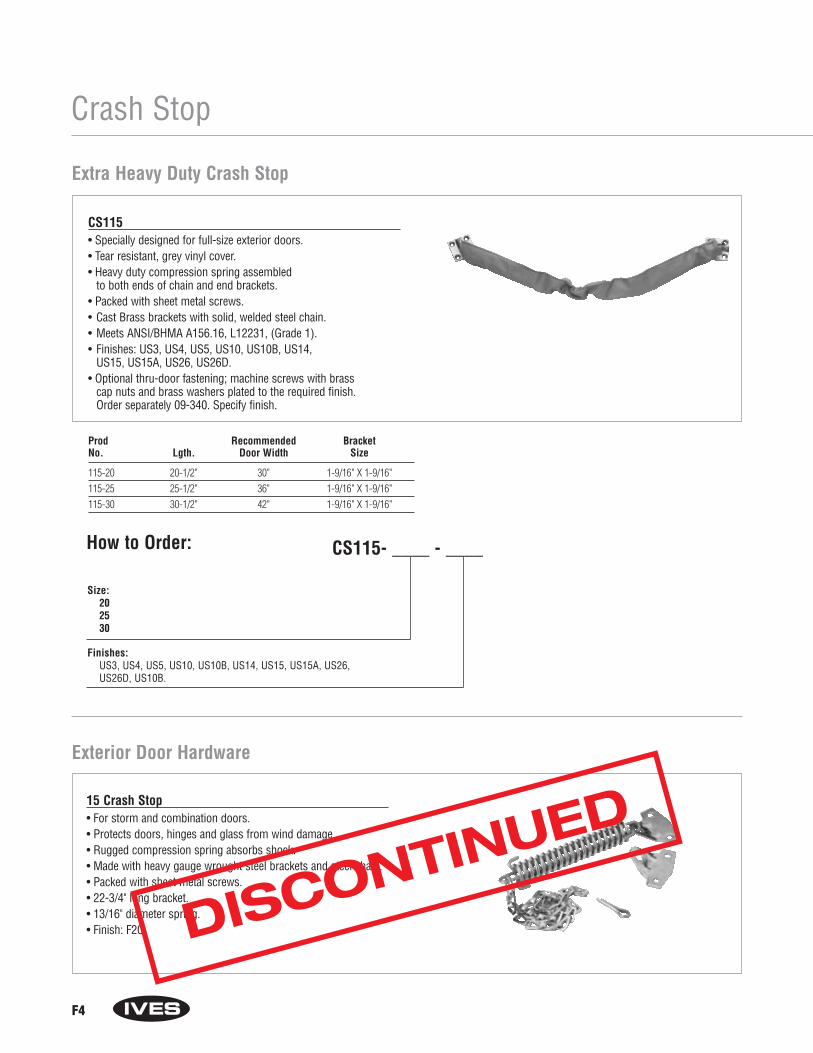
F4
Crash Stop
Extra Heavy Duty Crash Stop
Prod Recommended BracketNo. Lgth. Door Width Size
115-20 20-1/2" 30" 1-9/16" X 1-9/16"115-25 25-1/2" 36" 1-9/16" X 1-9/16"115-30 30-1/2" 42" 1-9/16" X 1-9/16"
CS115• Specially designed for full-size exterior doors.• Tear resistant, grey vinyl cover.• Heavy duty compression spring assembled
to both ends of chain and end brackets.• Packed with sheet metal screws.• Cast Brass brackets with solid, welded steel chain.• Meets ANSI/BHMA A156.16, L12231, (Grade 1).• Finishes: US3, US4, US5, US10, US10B, US14,
US15, US15A, US26, US26D.• Optional thru-door fastening; machine screws with brass
cap nuts and brass washers plated to the required finish. Order separately 09-340. Specify finish.
Size: 202530
Finishes: US3, US4, US5, US10, US10B, US14, US15, US15A, US26, US26D, US10B.
How to Order: CS115- ____ - ____
Exterior Door Hardware
15 Crash Stop• For storm and combination doors.• Protects doors, hinges and glass from wind damage.• Rugged compression spring absorbs shock.• Made with heavy gauge wrought steel brackets and steel chain.• Packed with sheet metal screws.• 22-3/4" long bracket.• 13/16" diameter spring.• Finish: F2C. DISCONTINUED

F5
Exterior Door Hardware
Screen Door Pull
25 • Made from cast aluminum or epoxy-coated aluminum.• Can also be used as a window lift, drawer or utility pull.• Finishes: A3, A4, A5, A10, A14, A92, A-A (almond), A-W (white),
A-BLK (black).
Dimensions:Overall Length: 4-7/8"Mounting Hole Center-to-Center: 4-1/8"Projection: 1-5/32"
980 • For wood storm doors 7/8" to 1-1/8" thick.• Reversible: fits right or left hand, inswinging or outswinging doors.• Security lock feature operates from inside rose.• Solid brass safety strike assures latching and is designed to
compensate for air pressure build-up between doors.• Made from wrought brass.• Finishes: B3, B5, B10B, B15, B15A, B26, B26D.
Dimensions:Backset: 1-3/4"Rose Diameter: 1-7/8"Knob Diameter: 1-3/4"Knob Projection: 2"Lever Length: 1-3/4"Lever Projection: 1-7/8"
Storm Door Latch
780 • Polished wrought brass front plate, inset with satin black plastic
push plate.• Chime case in ivory plastic.• Ideal for interior apartment doors, condominiums and hotel/motels.• Combines low initial cost with fast, economical installation.• Unique placement of name and apartment number cards conceals
mounting screws.• Optical glass viewer permits screening of callers and is shutter
controlled to insure one way vision only.• Two-tone, mellow and resonant chime.• Requires only one hole, 1" in diameter, through door.• Fits 1-1/4" through 1-3/4" doors. Contact factory for use on other
thickness doors.• Packed with template and installation instructions, screws, name and
number cards.• Furnished with 700 viewer.
Non-Electric Door Chime
Prod Front Plate Chime Case FinishesNo. Width Height Proj. Width Height Proj. Front plate Chime Case
780 2-1/2" 4-9/16" 1" 2-3/4" 6-1/16" 2" B3, B26D Ivory Plastic
DISCONTINUED
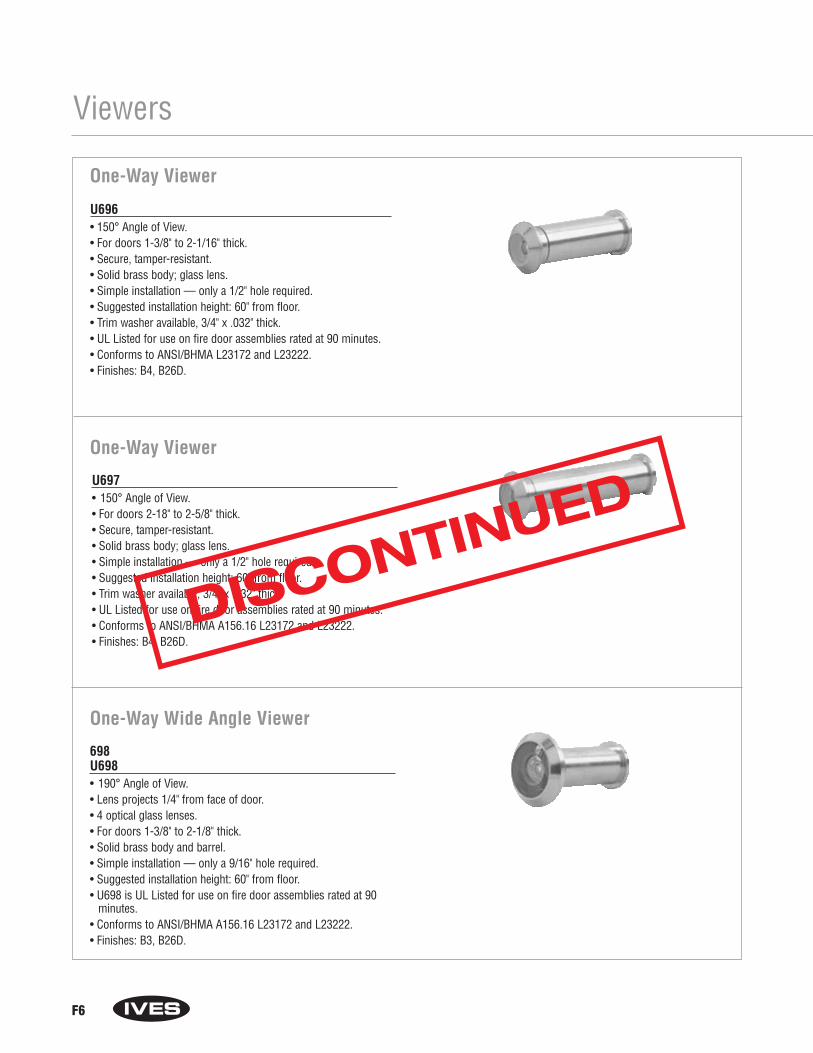
F6
Viewers
One-Way Viewer
U696 • 150° Angle of View.• For doors 1-3/8" to 2-1/16" thick.• Secure, tamper-resistant.• Solid brass body; glass lens.• Simple installation — only a 1/2" hole required.• Suggested installation height: 60" from floor.• Trim washer available, 3/4" x .032" thick.• UL Listed for use on fire door assemblies rated at 90 minutes.• Conforms to ANSI/BHMA L23172 and L23222.• Finishes: B4, B26D.
U697 • 150° Angle of View.• For doors 2-18" to 2-5/8" thick.• Secure, tamper-resistant.• Solid brass body; glass lens.• Simple installation — only a 1/2" hole required.• Suggested installation height: 60" from floor.• Trim washer available, 3/4" x .032" thick.• UL Listed for use on fire door assemblies rated at 90 minutes.• Conforms to ANSI/BHMA A156.16 L23172 and L23222.• Finishes: B4, B26D.
One-Way Viewer
698U698• 190° Angle of View.• Lens projects 1/4" from face of door.• 4 optical glass lenses.• For doors 1-3/8" to 2-1/8" thick.• Solid brass body and barrel.• Simple installation — only a 9/16" hole required.• Suggested installation height: 60" from floor.• U698 is UL Listed for use on fire door assemblies rated at 90
minutes.• Conforms to ANSI/BHMA A156.16 L23172 and L23222.• Finishes: B3, B26D.
One-Way Wide Angle Viewer
DISCONTINUED
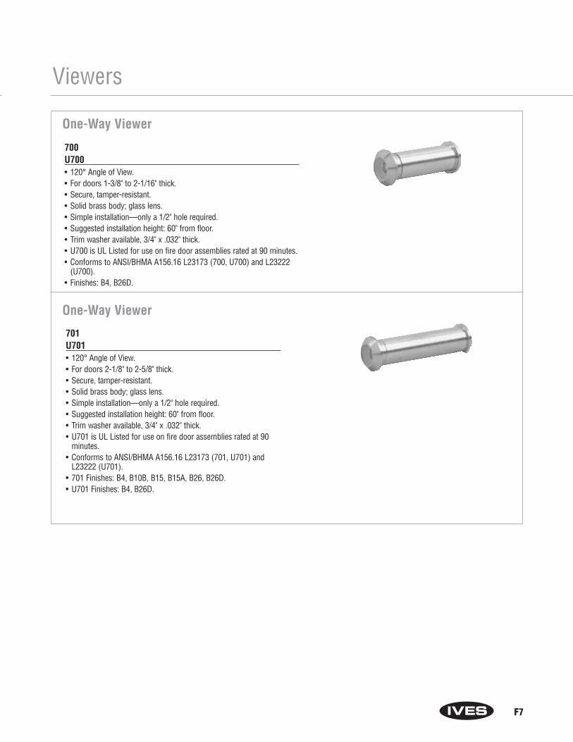
F7
Viewers
One-Way Viewer
700U700• 120° Angle of View.• For doors 1-3/8" to 2-1/16" thick.• Secure, tamper-resistant.• Solid brass body; glass lens.• Simple installation—only a 1/2" hole required.• Suggested installation height: 60" from floor.• Trim washer available, 3/4" x .032" thick.• U700 is UL Listed for use on fire door assemblies rated at 90 minutes.• Conforms to ANSI/BHMA A156.16 L23173 (700, U700) and L23222
(U700).• Finishes: B4, B26D.
701U701• 120° Angle of View.• For doors 2-1/8" to 2-5/8" thick.• Secure, tamper-resistant.• Solid brass body; glass lens.• Simple installation—only a 1/2" hole required.• Suggested installation height: 60" from floor.• Trim washer available, 3/4" x .032" thick.• U701 is UL Listed for use on fire door assemblies rated at 90
minutes.• Conforms to ANSI/BHMA A156.16 L23173 (701, U701) and
L23222 (U701).• 701 Finishes: B4, B10B, B15, B15A, B26, B26D.• U701 Finishes: B4, B26D.
One-Way Viewer
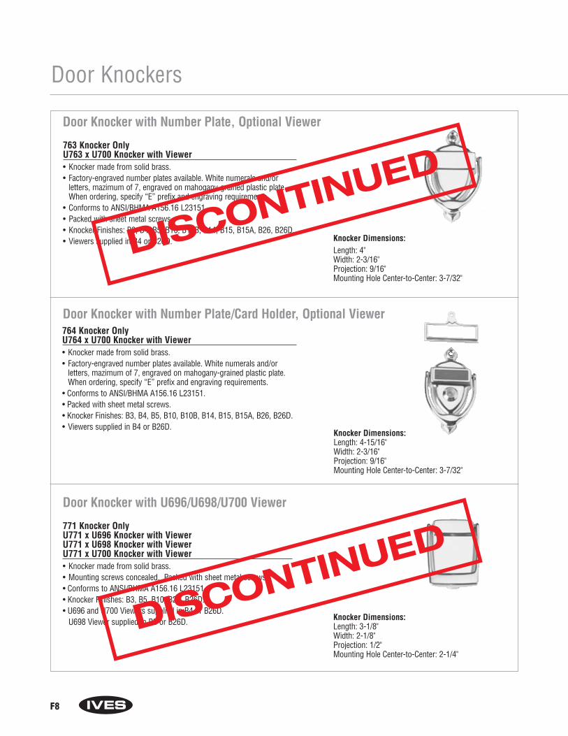
F8
Door Knockers
Door Knocker with Number Plate, Optional Viewer
763 Knocker OnlyU763 x U700 Knocker with Viewer• Knocker made from solid brass.• Factory-engraved number plates available. White numerals and/or
letters, mazimum of 7, engraved on mahogany-grained plastic plate.When ordering, specify “E” prefix and engraving requirements.
• Conforms to ANSI/BHMA A156.16 L23151.• Packed with sheet metal screws.• Knocker Finishes: B3, B4, B5, B10, B10B, B14, B15, B15A, B26, B26D.• Viewers supplied in B4 or B26D. Knocker Dimensions:
Length: 4"Width: 2-3/16" Projection: 9/16"Mounting Hole Center-to-Center: 3-7/32"
764 Knocker OnlyU764 x U700 Knocker with Viewer• Knocker made from solid brass.• Factory-engraved number plates available. White numerals and/or
letters, mazimum of 7, engraved on mahogany-grained plastic plate.When ordering, specify “E” prefix and engraving requirements.
• Conforms to ANSI/BHMA A156.16 L23151.• Packed with sheet metal screws.• Knocker Finishes: B3, B4, B5, B10, B10B, B14, B15, B15A, B26, B26D.• Viewers supplied in B4 or B26D.
Knocker Dimensions:Length: 4-15/16"Width: 2-3/16" Projection: 9/16"Mounting Hole Center-to-Center: 3-7/32"
Door Knocker with Number Plate/Card Holder, Optional Viewer
Door Knocker with U696/U698/U700 Viewer
771 Knocker OnlyU771 x U696 Knocker with ViewerU771 x U698 Knocker with ViewerU771 x U700 Knocker with Viewer• Knocker made from solid brass.• Mounting screws concealed. Packed with sheet metal screws.• Conforms to ANSI/BHMA A156.16 L23151.• Knocker Finishes: B3, B5, B10, B26, B26D.• U696 and U700 Viewers supplied in B4 or B26D.
U698 Viewer supplied in B3 or B26D. Knocker Dimensions:Length: 3-1/8"Width: 2-1/8" Projection: 1/2"Mounting Hole Center-to-Center: 2-1/4"
DISCONTINUED
DISCONTINUED
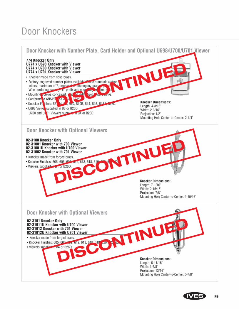
F9
Door Knockers
774 Knocker OnlyU774 x U698 Knocker with ViewerU774 x U700 Knocker with ViewerU774 x U701 Knocker with Viewer• Knocker made from solid brass.• Factory-engraved number plates available. White numerals and/or
letters, mazimum of 7, engraved on mahogany-grained plastic plate.When ordering, specify “E” prefix and engraving requirements.
• Mounting screws concealed. Packed with sheet metal screws.• Conforms to ANSI/BHMA A156.16 L23151.• Knocker Finishes: B3, B4, B5, B10, B10B, B14, B15, B15A, B26D.• U698 Viewer supplied in B3 or B26D.
U700 and U701 Viewers supplied in B4 or B26D.
Knocker Dimensions:Length: 4-3/16"Width: 2-3/16" Projection: 1/2"Mounting Hole Center-to-Center: 2-1/4"
Door Knocker with Number Plate, Card Holder and Optional U698/U700/U701 Viewer
Door Knocker with Optional Viewers
02-3100 Knocker Only02-31001 Knocker with 700 Viewer02-31001U Knocker with U700 Viewer02-31002 Knocker with 701 Viewer• Knocker made from forged brass.• Knocker Finishes: 605, 606, 609, 612, 613, 618, 619, 620, 625, 626.• Viewers supplied in B4 or B26D.
Knocker Dimensions:Length: 7-1/16" Width: 2-15/16" Projection: 7/8"Mounting Hole Center-to-Center: 4-15/16"
02-3101 Knocker Only02-31011U Knocker with U700 Viewer02-31012 Knocker with 701 Viewer02-31012U Knocker with U701 Viewer• Knocker made from forged brass.• Knocker Finishes: 605, 606, 609, 612, 613, 618, 619, 620, 625, 626.• Viewers supplied in B4 or B26D.
Knocker Dimensions:Length: 6-11/16" Width: 1-7/8" Projection: 13/16"Mounting Hole Center-to-Center: 5-7/8"
Door Knocker with Optional Viewers
DISCONTINUED
DISCONTINUED
DISCONTINUED
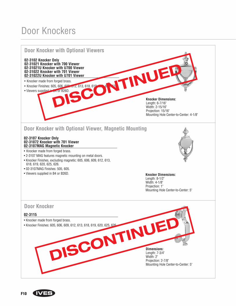
F10
Door Knockers
Door Knocker with Optional Viewers
02-3102 Knocker Only02-31021 Knocker with 700 Viewer02-31021U Knocker with U700 Viewer02-31022 Knocker with 701 Viewer02-31022U Knocker with U701 Viewer• Knocker made from forged brass.• Knocker Finishes: 605, 606, 609, 612, 613, 618, 619, 620, 625, 626.• Viewers supplied in B4 or B26D.
Knocker Dimensions:Length: 6-7/16" Width: 2-15/16" Projection: 15/16"Mounting Hole Center-to-Center: 4-1/8"
02-3107 Knocker Only02-31072 Knocker with 701 Viewer02-3107MAG Magnetic Knocker• Knocker made from forged brass.• 2-3107 MAG features magnetic mounting on metal doors.• Knocker Finishes, excluding magnetic: 605, 606, 609, 612, 613,
618, 619, 620, 625, 626.• 02-3107MAG Finishes: 505, 605.• Viewers supplied in B4 or B26D. Knocker Dimensions:
Length: 8-1/2" Width: 4-1/8" Projection: 1"Mounting Hole Center-to-Center: 5"
Door Knocker with Optional Viewer, Magnetic Mounting
Door Knocker 02-3115 • Knocker made from forged brass.• Knocker Finishes: 605, 606, 609, 612, 613, 618, 619, 620, 625, 626.
Dimensions:Length: 7-3/4" Width: 2" Projection: 2-7/8"Mounting Hole Center-to-Center: 5"
DISCONTINUED
DISCONTINUED
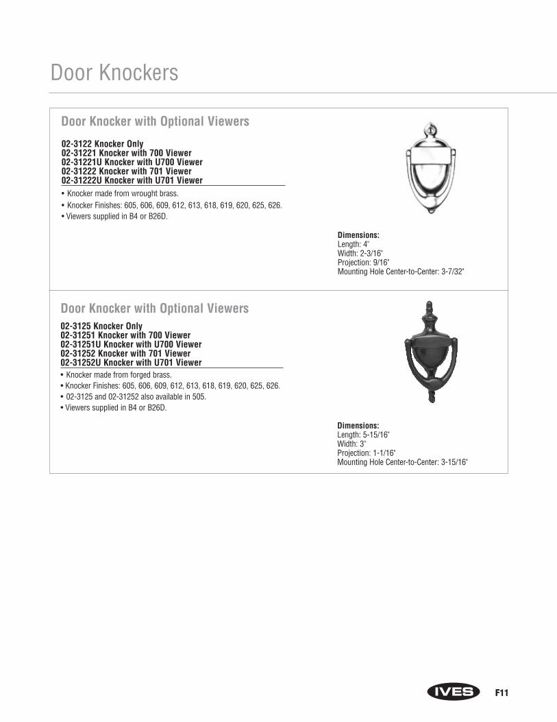
F11
Door Knockers
02-3122 Knocker Only02-31221 Knocker with 700 Viewer02-31221U Knocker with U700 Viewer02-31222 Knocker with 701 Viewer02-31222U Knocker with U701 Viewer• Knocker made from wrought brass.• Knocker Finishes: 605, 606, 609, 612, 613, 618, 619, 620, 625, 626.• Viewers supplied in B4 or B26D.
Dimensions:Length: 4" Width: 2-3/16" Projection: 9/16"Mounting Hole Center-to-Center: 3-7/32"
Door Knocker with Optional Viewers
02-3125 Knocker Only02-31251 Knocker with 700 Viewer02-31251U Knocker with U700 Viewer02-31252 Knocker with 701 Viewer02-31252U Knocker with U701 Viewer• Knocker made from forged brass.• Knocker Finishes: 605, 606, 609, 612, 613, 618, 619, 620, 625, 626.• 02-3125 and 02-31252 also available in 505.• Viewers supplied in B4 or B26D.
Dimensions:Length: 5-15/16" Width: 3" Projection: 1-1/16"Mounting Hole Center-to-Center: 3-15/16"
Door Knocker with Optional Viewers

F12
House Numbers
Century House Numbers02-30_0• 4" High.• Made from cast brass.• Brass screws included.• Finish: 605.
02-30_1• 6" High.• Made from forged brass.• Brass screws included.• Finish: 605.
Century House Numbers
Heritage House Number02-30_3• 2-3/4" High.• Colonial styling.• Made from cast brass.• Fits limited space; often
used for apartments and hotel rooms.• Conforms to ANSI/BHMA A156.16 L13181.• Brass brads included.• Finish: 605.
Model House Number
02-3000 #0
02-3010 #102-3020 #202-3030 #302-3040 #402-3050 #502-3060 #602-3070 #702-3080 #802-3090 #9
Model House Number
02-3001 #002-3011 #102-3021 #202-3031 #302-3041 #402-3051 #502-3061 #602-3071 #702-3081 #802-3091 #9
Model House Number02-3003 #002-3013 #102-3023 #202-3033 #302-3043 #402-3053 #502-3063 #602-3073 #702-3083 #802-3093 #9
DISCONTINUED
DISCONTINUED
DISCONTINUED
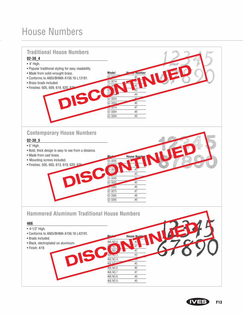
F13
House Numbers
02-30_4• 4" High.• Popular traditional styling for easy readability.• Made from solid wrought brass.• Conforms to ANSI/BHMA A156.16 L13181.• Brass brads included.• Finishes: 605, 609, 619, 620, 626.
Traditional House Numbers
Model House Number02-3004 #002-3014 #102-3024 #202-3034 #302-3044 #402-3054 #502-3064 #602-3074 #702-3084 #802-3094 #9
Contemporary House Numbers02-30_5• 5" High.• Bold, thick design is easy to see from a distance.• Made from cast brass.• Mounting screws included.• Finishes: 505, 605, 613, 619, 620, 625.
Model House Number02-3005 #002-3015 #102-3025 #202-3035 #302-3045 #402-3055 #502-3065 #602-3075 #702-3085 #802-3095 #9
466• 4-1/2" High.• Conforms to ANSI/BHMA A156.16 L43191.• Brads included.• Black, electroplated on aluminum.• Finish: A19.
Hammered Aluminum Traditional House Numbers
Model House Number
466 NO.0 #0466 NO.1 #1466 NO.2 #2466 NO.3 #3466 NO.4 #4466 NO.5 #5466 NO.6 #6466 NO.7 #7466 NO.8 #8466 NO.9 #9
DISCONTINUED
DISCONTINUED
DISCONTINUED
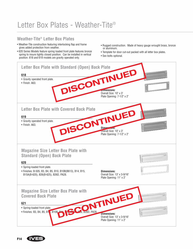
Letter Box Plate with Covered Back Plate
619• Gravity operated front plate.• Finish: A63.
620• Spring-loaded front plate.• Finishes: B-505, B3, B4, B5, B10, B10B(B613), B14, B15,
B15A(B-620), B26(B-625), B26D, PA28.
Magazine Size Letter Box Plate withStandard (Open) Back Plate
Dimensions:Overall Size: 10" x 3"Plate Opening: 7-1/2" x 2"
Dimensions:Overall Size: 13" x 3-9/16"Plate Opening: 11" x 2"
621• Spring-loaded front plate.• Finishes: B3, B4, B5, B10, B10B, B14, B15, B15A, B26, B26D, PA28.
Magazine Size Letter Box Plate withCovered Back Plate
Dimensions:Overall Size: 13" x 3-9/16"Plate Opening: 11" x 2"
F14
Letter Box Plates - Weather-Tite®
618• Gravity operated front plate.• Finish: A63.
Letter Box Plate with Standard (Open) Back Plate
Dimensions:Overall Size: 10" x 3"Plate Opening: 7-1/2" x 2"
Weather-Tite® Letter Box Plates• Weather-Tite construction featuring interlocking flap and frame
gives added protection from weather.• 620 Series Models feature spring loaded front plate features bronze
spring to insure tightly closed position. Can be installed in verticalposition. 618 and 619 models are gravity operated only.
• Rugged construction. Made of heavy gauge wrought brass, bronzeor aluminum.
• Template for door cut-out packed with all letter box plates.• Sex bolts optional.
DISCONTINUED
DISCONTINUED
DISCONTINUED

F15
Letter Box Plates - Weather-Tite®
Weather-Tite® Letter Box Plates• Weather-Tite construction featuring interlocking flap and frame
gives added protection from weather.• 620 Series Models feature spring loaded front plate features bronze
spring to insure tightly closed position. Can be installed in verticalposition. 618 and 619 models are gravity operated only.
• Rugged construction. Made of heavy gauge wrought brass, bronzeor aluminum.
• Template for door cut-out packed with all letter box plates.• Sex bolts optional.
Magazine Size Letter Box Plate withHood and Covered Back Plate622• Spring-loaded front plate.• Finish: B3, B4, B5, B10, B10B, B14, B15, B15A, B26, B26D. Dimensions:
Overall Size: 13" x 3-9/16"Plate Opening: 11" x 2" Hood Projection: 1-5/8"
623• Spring-loaded front plate.• Finishes: B3, B4, B5, B10, B10B, B14, B15, B15A, B26, B26D, PA28.
Letter Box Plate with Standard (Open) Back Plate
Dimensions:Overall Size: 10" x 3"Plate Opening: 7-1/2" x 2"
624• Spring-loaded front plate.• Finishes: B3, B4, B5, B10, B10B, B14, B15, B15A, B26, B26D, PA28.
Letter Box Plate with Covered Back Plate
Dimensions:Overall Size: 10" x 3"Plate Opening: 7-1/2" x 2"
Letter Box Plate with Hood and Covered Back Plate
625• Spring-loaded front plate.• Finishes: B3, B4, B5, B10, B10B, B14, B15, B15A, B26D, PA28. Dimensions:
Overall Size: 10" x 3"Plate Opening: 7-1/2" x 2" Hood Projection: 1-5/8"
DISCONTINUED
DISCONTINUED
DISCONTINUED
DISCONTINUED

626• Spring-loaded front plate.• Finishes: B-505, B3, B4, B5, B10, B10B(B-613), B14,
B-15(B-619), B15A(B-620), B26(B-625), B26D, PA28.
Letter Box Plate with Standard (Open) Back Plate
Dimensions:Overall Size: 8-3/4" x 2-7/8"Plate Opening: 7" x 1-7/8"
627• Spring-loaded front plate.• Finishes: B3, B4, B5, B10, B10B, B14, B15, B15A, B26, B26D.
Letter Box Plate with Covered Back Plate
Dimensions:Overall Size: 8-3/4" x 2-7/8"Plate Opening: 7" x 1-7/8"
F16
Letter Box Plates - Weather-Tite®
Weather-Tite® Letter Box Plates• Weather-Tite construction featuring interlocking flap and frame
gives added protection from weather.• 620 Series Models feature spring loaded front plate features bronze
spring to insure tightly closed position. Can be installed in verticalposition. 618 and 619 models are gravity operated only.
• Rugged construction. Made of heavy gauge wrought brass, bronzeor aluminum.
• Template for door cut-out packed with all letter box plates• Sex bolts optional.
Sleeves for use with Letter Box Plates600 Sleeve for use with 626 and 627 Letter Box Plates601 Sleeve for use with 620, 621 and 622 Letter Box Plates602 Sleeve for use with 618, 619, 623 and 624 Letter Box Plates• Made of stainless steel.• For 1-3/4" hollow core doors.
DISCONTINUED
DISCONTINUED
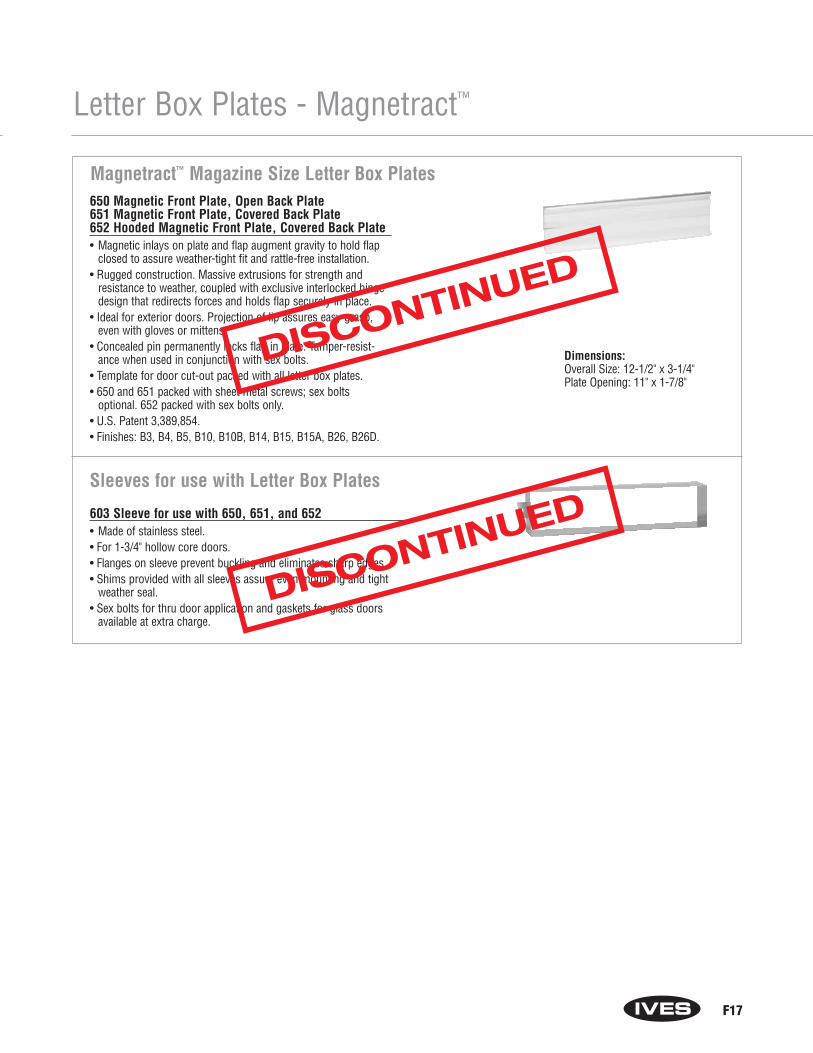
F17
Letter Box Plates - Magnetract™
Magnetract™ Magazine Size Letter Box Plates650 Magnetic Front Plate, Open Back Plate651 Magnetic Front Plate, Covered Back Plate652 Hooded Magnetic Front Plate, Covered Back Plate• Magnetic inlays on plate and flap augment gravity to hold flap
closed to assure weather-tight fit and rattle-free installation.• Rugged construction. Massive extrusions for strength and
resistance to weather, coupled with exclusive interlocked hingedesign that redirects forces and holds flap securely in place.
• Ideal for exterior doors. Projection of lip assures easy grasp,even with gloves or mittens.
• Concealed pin permanently locks flap in plate. Tamper-resist-ance when used in conjunction with sex bolts.
• Template for door cut-out packed with all letter box plates.• 650 and 651 packed with sheet metal screws; sex bolts
optional. 652 packed with sex bolts only.• U.S. Patent 3,389,854.• Finishes: B3, B4, B5, B10, B10B, B14, B15, B15A, B26, B26D.
603 Sleeve for use with 650, 651, and 652• Made of stainless steel.• For 1-3/4" hollow core doors.• Flanges on sleeve prevent buckling and eliminates sharp edges.• Shims provided with all sleeves assure even mounting and tight
weather seal.• Sex bolts for thru door application and gaskets for glass doors
available at extra charge.
Sleeves for use with Letter Box Plates
Dimensions:Overall Size: 12-1/2" x 3-1/4"Plate Opening: 11" x 1-7/8"
DISCONTINUED
DISCONTINUED
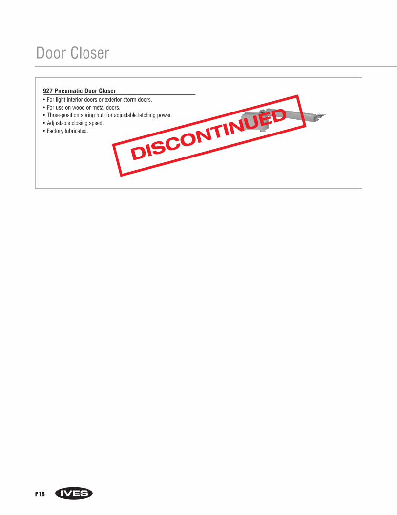
F18
Door Closer
927 Pneumatic Door Closer• For light interior doors or exterior storm doors.• For use on wood or metal doors.• Three-position spring hub for adjustable latching power.• Adjustable closing speed.• Factory lubricated.
DISCONTINUED

Section GLatches and Catches
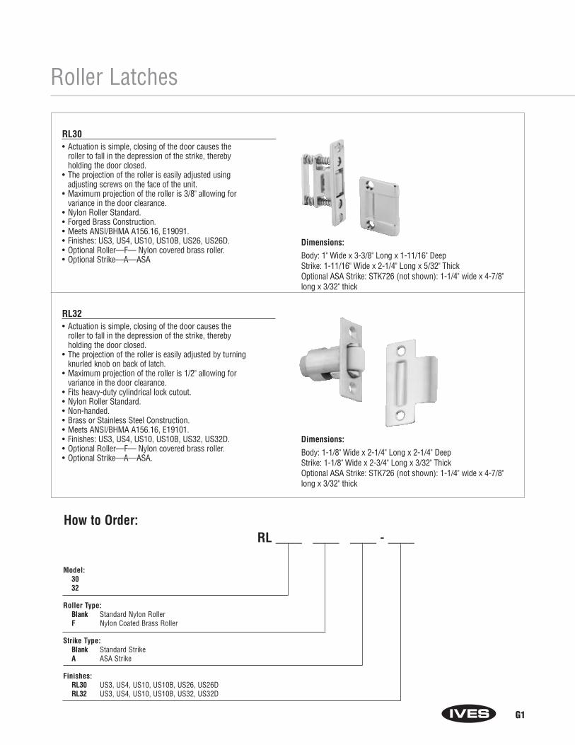
G1
Model:3032
Roller Type: Blank Standard Nylon RollerF Nylon Coated Brass Roller
Strike Type: Blank Standard StrikeA ASA Strike
Finishes: RL30 US3, US4, US10, US10B, US26, US26DRL32 US3, US4, US10, US10B, US32, US32D
Roller Latches
RL30• Actuation is simple, closing of the door causes the
roller to fall in the depression of the strike, thereby holding the door closed.
• The projection of the roller is easily adjusted using adjusting screws on the face of the unit.
• Maximum projection of the roller is 3/8" allowing for variance in the door clearance.
• Nylon Roller Standard.• Forged Brass Construction.• Meets ANSI/BHMA A156.16, E19091.• Finishes: US3, US4, US10, US10B, US26, US26D.• Optional Roller—F— Nylon covered brass roller.• Optional Strike—A—ASA
RL32• Actuation is simple, closing of the door causes the
roller to fall in the depression of the strike, thereby holding the door closed.
• The projection of the roller is easily adjusted by turning knurled knob on back of latch.
• Maximum projection of the roller is 1/2" allowing for variance in the door clearance.
• Fits heavy-duty cylindrical lock cutout.• Nylon Roller Standard.• Non-handed.• Brass or Stainless Steel Construction.• Meets ANSI/BHMA A156.16, E19101.• Finishes: US3, US4, US10, US10B, US32, US32D.• Optional Roller—F— Nylon covered brass roller.• Optional Strike—A—ASA.
How to Order:RL ____ ____ ____ - ____
Dimensions:
Body: 1" Wide x 3-3/8" Long x 1-11/16" DeepStrike: 1-11/16" Wide x 2-1/4" Long x 5/32" ThickOptional ASA Strike: STK726 (not shown): 1-1/4" wide x 4-7/8" long x 3/32" thick
Dimensions:
Body: 1-1/8" Wide x 2-1/4" Long x 2-1/4" DeepStrike: 1-1/8" Wide x 2-3/4" Long x 3/32" ThickOptional ASA Strike: STK726 (not shown): 1-1/4" wide x 4-7/8" long x 3/32" thick

Model: 36, 38 or 1152
Strike Type: (RL36 only)Blank Standard StrikeA ASA Strike
Finishes:RL36, RL38 US32DRL1152 US3, US4, US10, US10B, US26, US26D
RL36• Actuation is simple, closing of the door causes the
roller to fall in the depression of the strike, thereby holding the door closed.
• The projection of the roller is easily adjusted by turning slotted screw on back of latch.
• Maximum projection of the roller is 5/16" allowing for variance in the door clearance.
• Fits cylindrical lock cutout.• Nylon Roller.• Non-handed.• Stainless Steel Construction.• Meets ANSI/BHMA A156.16, L17082.• Finish: US32D• Optional Strike–A—ASA.
RL38• Actuation is simple, closing of the door causes the
roller to fall in the depression of the strike, thereby holding the door closed.
• The projection of the roller is easily adjusted by turning slotted screw.
• Maximum projection of the roller is 3/8" allowing for variance in the door clearance.
• Nylon Roller.• Non-handed.• Stainless Steel Construction.• Meets ANSI/BHMA A156.16, L27092.• Finish: US32D
RL1152• Combination of RL30 Roller Latch and Angle Stop.• Actuation is simple, closing of the door causes the
roller to fall in the depression of the strike, thereby holding the door closed.
• The projection of the roller is easily adjustable using adjusting screws on the face of the unit.
• Maximum projection of the roller is 3/8" allowing for variance in the door clearance.
• Nylon Roller Standard.• Forged Brass Construction.• Finishes: US3, US4, US10, US10B, US26 and US26D.
Roller Latches
G2
How to Order:RL ____ ____ - ____
Dimensions:
Body: 1" Wide x 2-1/4" Long x 2" DeepStrike: 1-1/8" Wide x 2-3/4" Long x 3/32" ThickOptional ASA Strike: STK726 (not shown): 1-1/4" wide x 4-7/8" long x 3/32" thick
Dimensions:
Body: 2" Tall x 1-3/8" Wide x 7/8" DeepStrike: 2-1/8" Tall x 1" Wide x 3/8" Deep
Dimensions:
Body: 4-1/2" Tall x 1-1/2" Wide x 1-3/4" Deep with 3/4" AngleStrike: 2-1/4" Tall x 1-1/8" Wide x 5/32" Thick
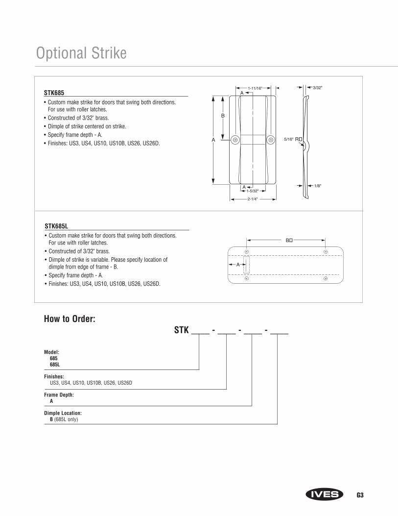
A
B
1-11/16"A
1-5/32"
2-1/4"
A 1/8"
5/16"
3/32"
R�
G3
B�
A
Model: 685685L
Finishes: US3, US4, US10, US10B, US26, US26D
Frame Depth: A
Dimple Location: B (685L only)
How to Order:STK ____ - ____ - ____ - ____
STK685• Custom make strike for doors that swing both directions.
For use with roller latches.• Constructed of 3/32" brass.• Dimple of strike centered on strike.• Specify frame depth - A.• Finishes: US3, US4, US10, US10B, US26, US26D.
STK685L• Custom make strike for doors that swing both directions.
For use with roller latches.• Constructed of 3/32" brass.• Dimple of strike is variable. Please specify location of
dimple from edge of frame - B.• Specify frame depth - A.• Finishes: US3, US4, US10, US10B, US26, US26D.
Optional Strike
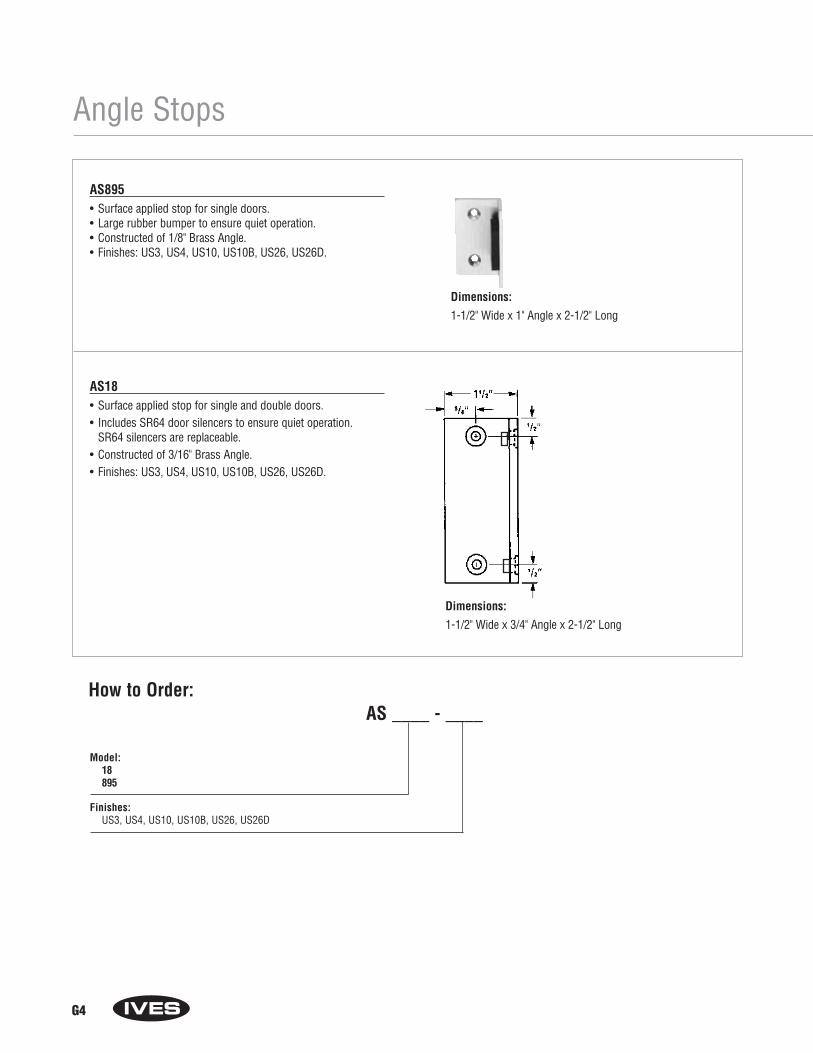
G4
Angle Stops
Dimensions:
1-1/2" Wide x 1" Angle x 2-1/2" Long
Dimensions:
1-1/2" Wide x 3/4" Angle x 2-1/2" Long
How to Order:AS ____ - ____
Model: 18895
Finishes: US3, US4, US10, US10B, US26, US26D
AS895• Surface applied stop for single doors.• Large rubber bumper to ensure quiet operation.• Constructed of 1/8" Brass Angle.• Finishes: US3, US4, US10, US10B, US26, US26D.
AS18• Surface applied stop for single and double doors.• Includes SR64 door silencers to ensure quiet operation.
SR64 silencers are replaceable.• Constructed of 3/16" Brass Angle.• Finishes: US3, US4, US10, US10B, US26, US26D.

Ball Catches
G5
CL21• Four-way catch with hexagon stud.• Ideal for holding medium duty doors.• The strike slides between two stainless steel balls that are under
spring tension. As the strike engages, the door is held tightly shut.• Strike can enter body from any direction.• Spring tension is easily adjusted to suit field conditions.• Body can be surface applied or mortised.• Brass construction.• Meets ANSI/BHMA A156.9.• Finish: US26D.
CL21A• Four-way catch with plate type strike.• Ideal for closet doors, access doors, hinged openings
and numerous other applications.• The strike slides between two stainless steel balls that are under
spring tension. As the strike engages, the door is held tightly shut.• Strike can enter body from any direction.• Spring tension is easily adjusted to suit field conditions.• Body can be surface applied or mortised.• Brass construction.• Meets ANSI/BHMA A156.9, B13292.• Finishes: US3, US4, US10, US26, US26D.
CL22• Three-way catch with plate type strike.• Ideal for smaller cabinet doors or panels.• The strike slides between two stainless steel balls that are under
spring tension. As the strike engages, the door is held tightly shut.• Strike can enter body from either side or front.• Spring tension is easily adjusted to suit field conditions.• Body can be surface applied or mortised.• Brass construction.• Meets ANSI/BHMA 156.9, B13302.• Finishes US3, US4, US10, US26, US26D.
Model: 2121A22
Finishes: CL21 US26DCL21A, CL22 US3, US4, US10, US26, US26D
How to Order:CL ____ - ____
Dimensions:
Body: 3" Tall x 3/4" Wide x 3/4" DeepStrike: 1-1/2" Tall x 3/4" Wide Hex
Dimensions:
Body: 3" Tall x 3/4" Wide x 3/4" DeepStrike: 1-3/4" Tall x 7/16" Wide x 7/8" Deep
Dimensions:
Body: 2-3/16" Tall x 1/2" Wide x 1/2" DeepStrike: 1-3/8" Tall x 3/8" Wide x 5/8" Deep

Invisible Latches
G6
CL11• Invisible latch is ideal for installations where no visible
latch is desired.• Unit can be installed at the top, bottom or side of the door.• Can be mortised into the stop or surface mounted to the stop.• Recommended for use on small panels, cabinet doors or light
weight closet doors.• Operation is simple, latching is accomplished by a slight push.
To unlatch the door, a harder push releases the door and pushesthe door out.
• Brass and plastic construction.• Meets ANSI/BHMA 156.9, B03272.• Finishes: US3, US4, US10, US26D.
Model: 111214
Finishes: US3, US4, US10, US26D
How to Order:CL ____ - ____
Dimensions:
Body: 1-7/8" Tall x 1-1/4" Wide x 7/16" ThickStrike: 1-5/16" Tall x 9/16" Wide x 9/16" High
Dimensions:
Body: 2-1/4" Tall x 1-1/4" Wide x 9/16" ThickStrike: 1-13/16" Tall x 5/8" Wide x 9/16" High
Dimensions:
Body: 2-15/16" Long x 1-11/16" Wide x 5/8" High
CL12• Invisible latch is ideal for installations where no visible
latch is desired.• Unit can be installed at the top, bottom or side of the door.• Can be mortised into the stop or surface mounted to the stop.• Recommended for use on larger panels or regular size doors.• Operation is simple, latching is accomplished by a slight push.
To unlatch the door, a harder push releases the door and pushesthe door out.
• Brass and plastic construction.• Meets ANSI/BHMA A156.9, B03272.• Finishes: US3, US4, US10, US26D.
CL14 Auxiliary Pusher• Aid in the operation of the CL11 and CL12 where hinges or
surrounding conditions prevent smooth operation of doors.• Provides 1-1/16" throw.• Nylon pusher.• Brass construction.• Meets ANSI/BHMA A156.9, B13282.• Finishes: US3, US4, US10, US26D.
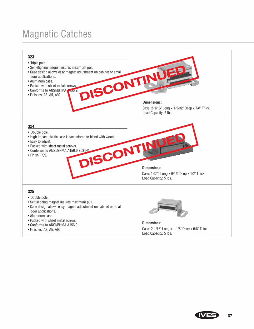
G7
Magnetic Catches
323 • Triple pole.• Self-aligning magnet insures maximum pull.• Case design allows easy magnet adjustment on cabinet or small.
door applications.• Aluminum case.• Packed with sheet metal screws.• Conforms to ANSI/BHMA A156.9.• Finishes: A3, A5, A92.
Dimensions:
Case: 2-1/16" Long x 1-5/32" Deep x 7/8" ThickLoad Capacity: 6 lbs.
Dimensions:
Case: 1-3/4" Long x 9/16" Deep x 1/2" Thick Load Capacity: 5 lbs.
Dimensions:
Case: 2-1/16" Long x 1-1/8" Deep x 5/8" Thick Load Capacity: 5 lbs.
324• Double pole.• High impact plastic case is tan colored to blend with wood.• Easy to adjust.• Packed with sheet metal screws.• Conforms to ANSI/BHMA A156.9 B03141.• Finish: P69.
325• Double pole.• Self aligning magnet insures maximum pull.• Case design allows easy magnet adjustment on cabinet or small
door applications.• Aluminum case.• Packed with sheet metal screws.• Conforms to ANSI/BHMA A156.9. • Finishes: A3, A5, A92.
DISCONTINUED
DISCONTINUED
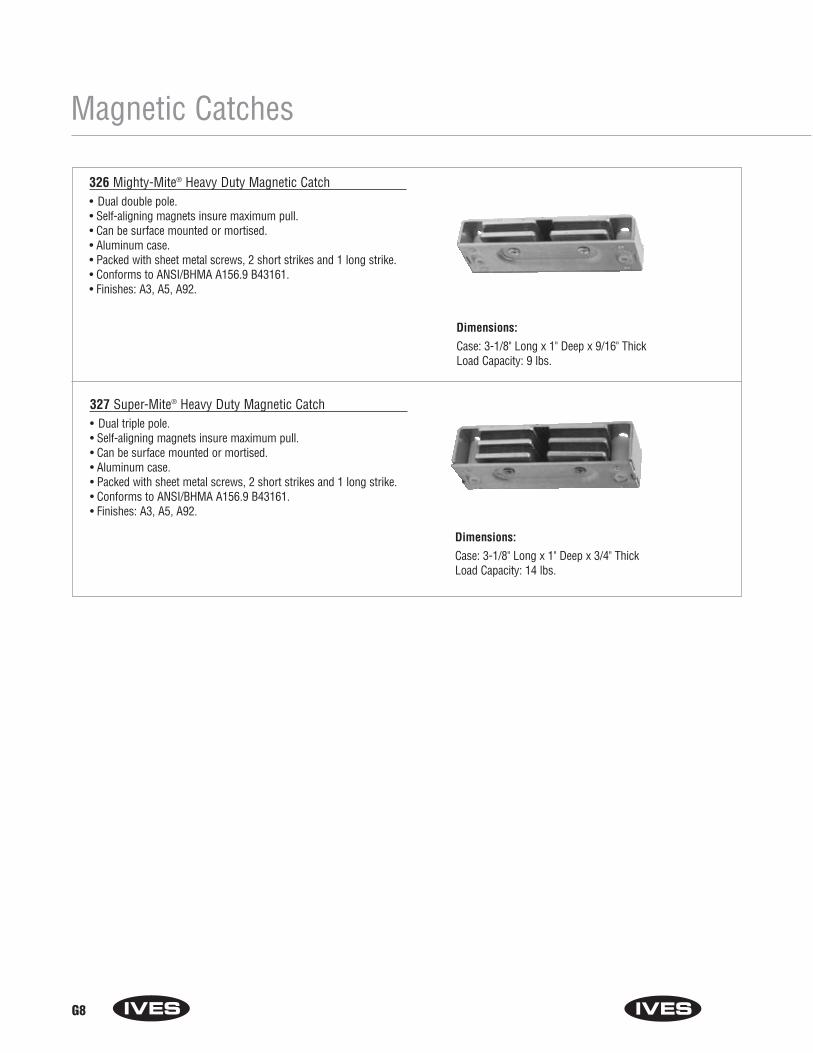
G8
Magnetic Catches
326 Mighty-Mite® Heavy Duty Magnetic Catch• Dual double pole.• Self-aligning magnets insure maximum pull.• Can be surface mounted or mortised.• Aluminum case.• Packed with sheet metal screws, 2 short strikes and 1 long strike.• Conforms to ANSI/BHMA A156.9 B43161.• Finishes: A3, A5, A92.
Dimensions:
Case: 3-1/8" Long x 1" Deep x 9/16" ThickLoad Capacity: 9 lbs.
Dimensions:
Case: 3-1/8" Long x 1" Deep x 3/4" ThickLoad Capacity: 14 lbs.
327 Super-Mite® Heavy Duty Magnetic Catch• Dual triple pole.• Self-aligning magnets insure maximum pull.• Can be surface mounted or mortised.• Aluminum case.• Packed with sheet metal screws, 2 short strikes and 1 long strike.• Conforms to ANSI/BHMA A156.9 B43161.• Finishes: A3, A5, A92.

G9
Roller Catches
330 Double Roller Catch• Independent rollers allow positive action and self-alignment.• Cushioned rollers absorb shock and noise, hold door away from
cabinet.• Surface application allows for easy adjustment.• Made from wrought steel.• Packed with screws and brads.• Conforms to ANSI/BHMA A156.9 B83071.• Finishes: F2C, F69.
Dimensions:
Face Plate: 2-1/4" x 7/8"Bore: 13/16" x 1-3/4"Strike: 2-1/4" x 1-5/8" Lip 1-13/16" to center
335• Smooth, positive latching action insured by powerful conical spring.• Durable nylon roller insures quiet operation.• Adjustable tension. Adjustments can be varied from 4 to 17 lbs. of
holding power making possible a wide range of door performance.• Easily installed on thin doors.• Full lip style strike designed for simplified mortising.• Made from wrought brass or wrought steel.• Packed with sheet metal screws.• Conforms to ANSI/BHMA A156.16 L27081 for brass and L87081 for
steel.• Finishes: B3, B4, B5, B10, B10B, B15, B15A, B19, B26, B26D, F3,
F5, F14.
Dimensions:
Face Plate: 2-1/4" x 7/8"Bore: 13/16" x 1-3/4"Strike: 2-1/4" x 7/8" Lip 1-1/8" to center
336• Smooth, positive latching action insured by powerful conical spring.• Durable nylon roller insures quiet operation.• Adjustable tension. Adjustments can be varied from 4 to 17 lbs. of
holding power making possible a wide range of door performance.• Easily installed on thin doors.• Standard box type strike designed for neat appearance.• Made from wrought brass or wrought steel.• Packed with sheet metal screws. • Conforms to ANSI/BHMA A156.16 L27081 for brass and L87801 for
steel.• Finishes: B3, B4, B5, B10, B10B, B15, B15A, B19, B26, B26D, F3,
F10, F14.
Dimensions:
Case: 1-1/4" x 11/16"Strike: 1-1/4" x 3/8"
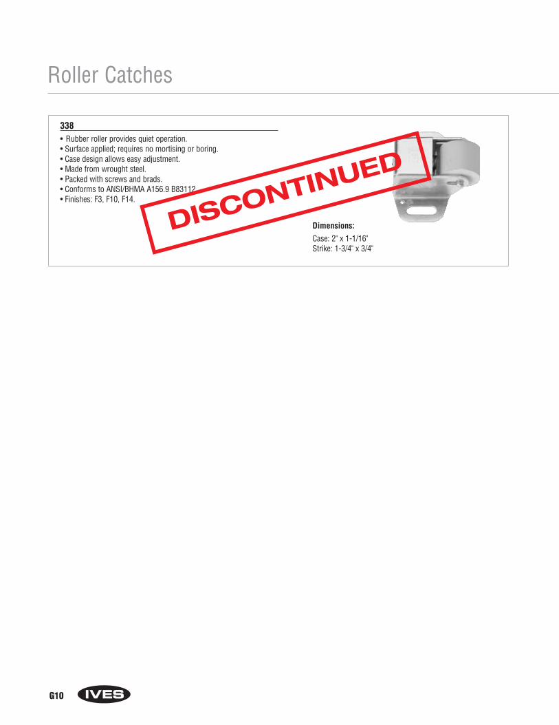
G10
Roller Catches
338• Rubber roller provides quiet operation.• Surface applied; requires no mortising or boring.• Case design allows easy adjustment.• Made from wrought steel.• Packed with screws and brads. • Conforms to ANSI/BHMA A156.9 B83112.• Finishes: F3, F10, F14.
Dimensions:
Case: 2" x 1-1/16"Strike: 1-3/4" x 3/4"
DISCONTINUED

G11
Ball Catches
345 Adjustable Ball Catch• Ideal for cabinets and small interior doors.• Free rolling ball insures smooth, positive and trouble-free action.• Adjustable threaded barrel compensates for various door
clearances.• Adjustable spring tension. • Made from wrought brass.• Conforms to ANSI/BHMA A156.9 B23013.• Finishes: B3, B4, B5, B10, B10B, B14, B15, B15A, B19, B26, B26D.
Dimensions:
Face Plate: 2-1/8" x 1"Bore: 7/8" x 1-3/8"Strike: 2-1/8" x 1-1/16". Lip 9/16" to center
346 Dual Adjustable Ball Catch • For catch in jamb installations.• Dual adjustment for door clearance and holding strength.• Narrow strike is designed for use where strike is mounted in door.• Free rolling ball insures smooth, positive and trouble-free action.• Adjustable threaded barrel compensates for various door
clearances.• Adjustable spring tension. • Made from wrought brass.• Conforms to ANSI/BHMA A156.9 B23013.• Finishes: B3, B4, B5, B10, B10B, B14, B15, B15A, B19, B26, B26D.
Dimensions:
Face Plate: 2-1/8" x 1"Bore: 7/8" x 1-3/8"Strike: 2-1/8" x 1-3/8". Lip 7/8" to center
347 Dual Adjustable Ball Catch • For catch in door installations.• Dual adjustment for door clearance and holding strength.• Lip strike is designed for use where strike is mounted in jamb.• Free rolling ball insures smooth, positive and trouble-free action.• Adjustable threaded barrel compensates for various door
clearances.• Adjustable spring tension.• Made from wrought brass.• Conforms to ANSI/BHMA A156.9 B23013.• Finishes: B3, B4, B5, B10, B10B, B14, B15, B15A, B19, B26, B26D.
Dimensions:
Face Plate: 1-1/2" x 3/4"Bore: 9/16" x 1"Strike: 1-1/2" x 25/32". Lip 13/32" to center
DISCONTINUED
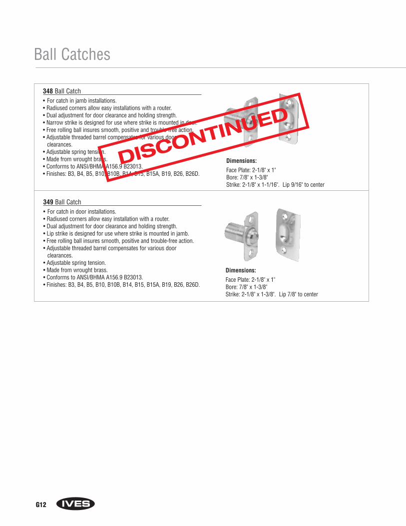
G12
Ball Catches
348 Ball Catch• For catch in jamb installations.• Radiused corners allow easy installations with a router.• Dual adjustment for door clearance and holding strength.• Narrow strike is designed for use where strike is mounted in door.• Free rolling ball insures smooth, positive and trouble-free action.• Adjustable threaded barrel compensates for various door
clearances.• Adjustable spring tension. • Made from wrought brass.• Conforms to ANSI/BHMA A156.9 B23013.• Finishes: B3, B4, B5, B10, B10B, B14, B15, B15A, B19, B26, B26D.
Dimensions:
Face Plate: 2-1/8" x 1"Bore: 7/8" x 1-3/8"Strike: 2-1/8" x 1-3/8". Lip 7/8" to center
349 Ball Catch • For catch in door installations.• Radiused corners allow easy installation with a router.• Dual adjustment for door clearance and holding strength.• Lip strike is designed for use where strike is mounted in jamb.• Free rolling ball insures smooth, positive and trouble-free action.• Adjustable threaded barrel compensates for various door
clearances.• Adjustable spring tension.• Made from wrought brass.• Conforms to ANSI/BHMA A156.9 B23013.• Finishes: B3, B4, B5, B10, B10B, B14, B15, B15A, B19, B26, B26D.
Dimensions:
Face Plate: 2-1/8" x 1"Bore: 7/8" x 1-3/8"Strike: 2-1/8" x 1-1/16". Lip 9/16" to center
DISCONTINUED
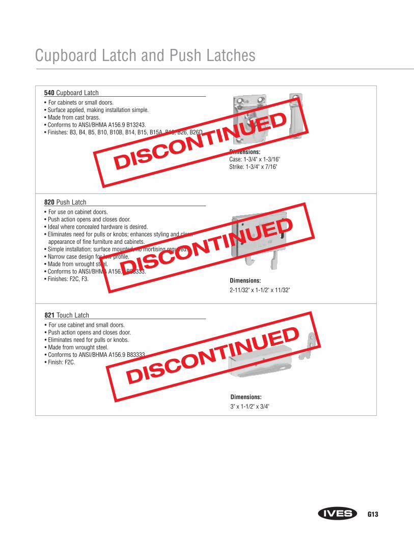
G13
Cupboard Latch and Push Latches
820 Push Latch• For use on cabinet doors.• Push action opens and closes door.• Ideal where concealed hardware is desired.• Eliminates need for pulls or knobs; enhances styling and clean
appearance of fine furniture and cabinets.• Simple installation; surface mounted, no mortising required.• Narrow case design for low profile.• Made from wrought steel.• Conforms to ANSI/BHMA A156.9 B83333.• Finishes: F2C, F3.
Dimensions:
3" x 1-1/2" x 3/4"
821 Touch Latch • For use cabinet and small doors.• Push action opens and closes door.• Eliminates need for pulls or knobs.• Made from wrought steel.• Conforms to ANSI/BHMA A156.9 B83333.• Finish: F2C.
Dimensions:
2-11/32" x 1-1/2" x 11/32"
540 Cupboard Latch• For cabinets or small doors.• Surface applied, making installation simple.• Made from cast brass.• Conforms to ANSI/BHMA A156.9 B13243.• Finishes: B3, B4, B5, B10, B10B, B14, B15, B15A, B19, B26, B26D.
Dimensions:Case: 1-3/4" x 1-3/16"Strike: 1-3/4" x 7/16"DISCONTINUED
DISCONTINUED
DISCONTINUED

G14
Mortise Door Bolts
S48 Mortise Door Bolt• Brass oval turn knob and escutcheon.• Steel bolt for extra strength. Rack is milled for precision fit with
pinion.• Conforms to design requirements of ANSI A156.16.• Finishes: B3, B4, B5, B10, B10B, B14, B15, B15A, B26, B26D.
Dimensions:
Face Plate on all models: 2-3/4" x 13/16"Bolt Throw: 1/2"Strike: 2-1/2" x 13/16"
150/152/154 Mortise Door Bolts151/153/155 Mortise Door Bolts• Only 1/4" turn of thumbturn or knob to lock or unlock door.• 150, 152, 154 have solid brass thumbturn and escutcheon.• 151, 153, 155 have solid brass oval turn knob and escutcheon.• Precision molded, slim aluminum case treated for maximum rust
resistance.• Heat-treated, copper impregnated allow steel hub for superior
strength and permanently lubricated cam action.• Retains unequaled, smooth positive operation.• Simplified installation—one-step mortise.• Optional emergency release trim available.• Conforms to design requirements of ANSI A156.16.• 150, 152, 154 are packed with thumbturn, escutcheon, bolt, strike
and screws.• 151, 153, 155 are packed with oval turn knob, escutcheon, bolt,
strike and screws.• Finishes: B3, B4, B5, B10, B10B, B14, B15, B15A, B19, B26, B26D.
Dimensions:
Backset: 1-3/4"Bolt Throw: 1/2"Bolt Diameter: 1/2"Case: 2-1/2" L x 9/16" diameterStrike: 1-3/4" x 7/8"
Model Backset Case Dimension Operation150 1-3/4" 1-5/8" x 2-1/4" x 9/16" Thumbturn151 1-3/4" 1-5/8" x 2-1/4" x 9/16" Oval turn knob152 2-1/2" 1-5/8" x 3" x 9/16" Thumbturn153 2-1/2" 1-5/8" x 3" x 9/16" Oval turn knob154 2-3/4" 1-5/8" x 3-1/4" x 9/16" Thumbturn155 2-3/4" 1-5/8" x 3-1/4" x 9/16" Oval turn knob
Trim Components For use with Mortise Door Bolts 150, 151, 152, 153, 154,155• 5 Emergency Key.• 145 Thumbturn for use with 150, 152, 154.• 146 Escutcheon for use with 150, 152, 154.• 145 x 146 Thumbturn and Escutcheon for use with 150, 152, 154.• 147 Oval turn knob for use with 151, 153, 155.• 148 Escutcheon for use with 151, 153, 155.• 147 x 148 Oval Turn Knob and Escutcheon for use with 151, 153,
155.
Thumbturns, oval turn knobs, and escutcheons available in same finishes as mortise door bolts
DISCONTINUED
Section HHooks and Brackets
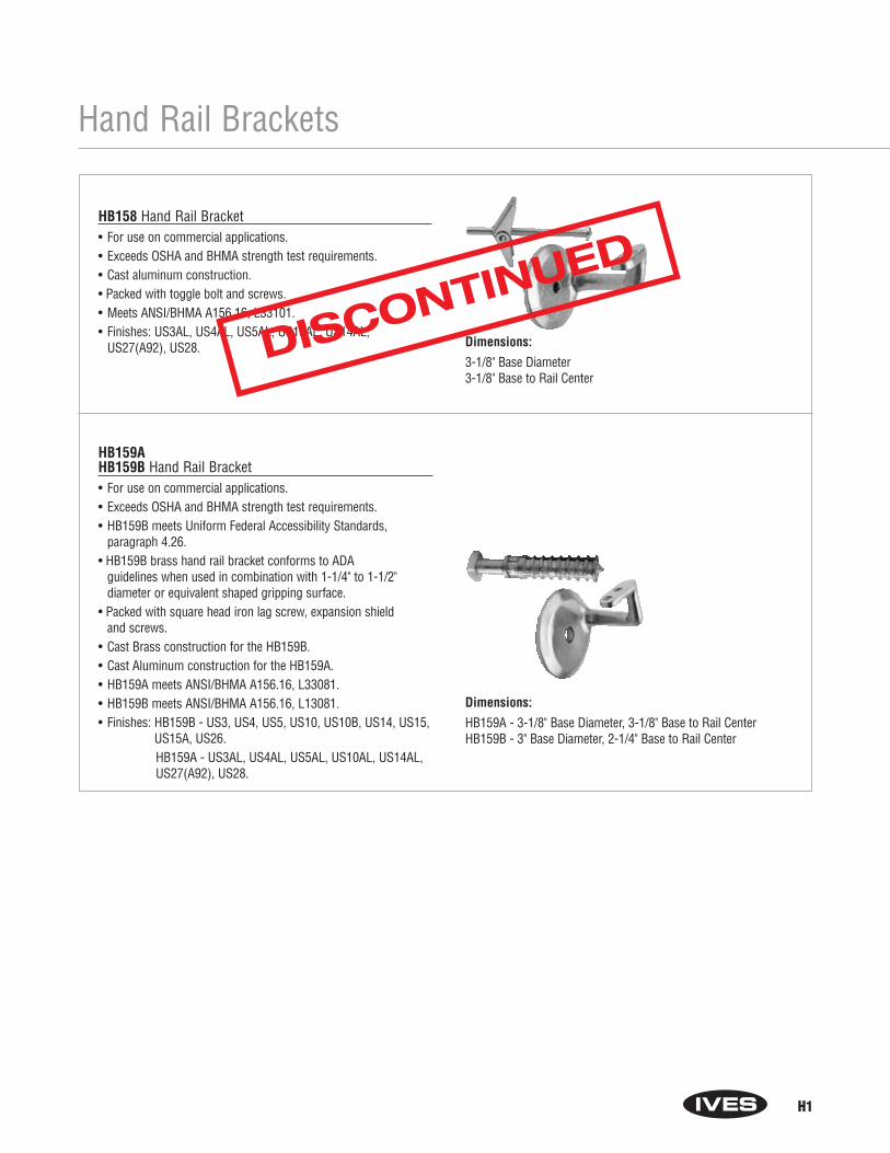
H1
Hand Rail Brackets
Dimensions:
HB159A - 3-1/8" Base Diameter, 3-1/8" Base to Rail CenterHB159B - 3" Base Diameter, 2-1/4" Base to Rail Center
HB159A HB159B Hand Rail Bracket• For use on commercial applications.• Exceeds OSHA and BHMA strength test requirements. • HB159B meets Uniform Federal Accessibility Standards,
paragraph 4.26.• HB159B brass hand rail bracket conforms to ADA
guidelines when used in combination with 1-1/4" to 1-1/2" diameter or equivalent shaped gripping surface.
• Packed with square head iron lag screw, expansion shield and screws.
• Cast Brass construction for the HB159B.• Cast Aluminum construction for the HB159A.• HB159A meets ANSI/BHMA A156.16, L33081.• HB159B meets ANSI/BHMA A156.16, L13081.• Finishes: HB159B - US3, US4, US5, US10, US10B, US14, US15,
US15A, US26.HB159A - US3AL, US4AL, US5AL, US10AL, US14AL, US27(A92), US28.
HB158 Hand Rail Bracket• For use on commercial applications.• Exceeds OSHA and BHMA strength test requirements. • Cast aluminum construction.• Packed with toggle bolt and screws.• Meets ANSI/BHMA A156.16, L33101.• Finishes: US3AL, US4AL, US5AL, US10AL, US14AL,
US27(A92), US28. Dimensions:
3-1/8" Base Diameter3-1/8" Base to Rail Center
DISCONTINUED

H2
Dimensions:
2-3/4" Tall x 1-3/4" Wide
Hand Rail Brackets
HB162 Adjustable Hand Rail Bracket• For horizontal rail installations in institutional and
commercial buildings.• Rust resistant. • Exceeds OSHA and BHMA strength test requirements. • Adjustable brackets compensate for irregularities in wall,
adjustable from 1-1/2" to 2" wall clearance.• Stainless steel 1/4"-20 button head socket screw and stainless
steel self-locking hex nut provide strong, rigid assembly.• Extruded aluminum construction.• Finish: US28.• Specify desired wall fasteners:
“W” for wood screws or “T” for toggle bolts.
How to Order:
HB162 - ____ - ____
Finish: US28
Fastener: Blank Screw with expansion shieldW Wood screws onlyT Screw with toggle bolts
Dimensions:
059 Base: 2-1/4" H x 1-3/8" W
059 Base to Center of Rail: 2-7/16"
59 Aluminum Base: 2-13/16" H x 1-1/2" W
59 Brass Base: 2-15/16" H x 1-1/2" W
59 Base to Center of Rail: 2-3/4"
059 & 59 Hand Rail Bracket• 059 made from solid brass, cast aluminum or epoxy-coated
aluminum.• 59 made from cast brass or cast aluminum.• Large faceplate for secure attachment to wall.• Features solid construction for increased strength.• 59 conforms to ANSI/BHMA A156.16 L13061 for brass and
L33061 for aluminum.• Brass Finishes: B3 (B-605), B4, B5, B10, B10B (B-613), B14,
B15 (B-619), B15A (B-620), B19, B26 (B-625), B26D.• Aluminum Finishes: A3, A4, A5, A10, A10B, A14, A92.• Epoxy-Coated Aluminum Finishes: White A-W, Black A-BLK,
Almond A-A.
DISCONTINUED
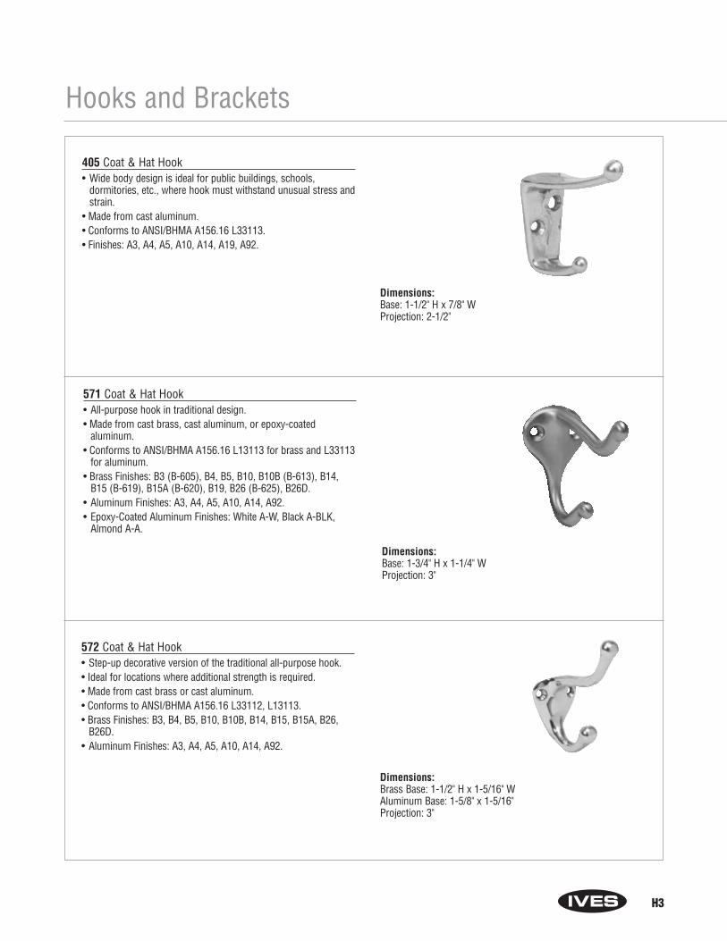
H3
Dimensions:Base: 1-1/2" H x 7/8" WProjection: 2-1/2"
Hooks and Brackets
405 Coat & Hat Hook• Wide body design is ideal for public buildings, schools,
dormitories, etc., where hook must withstand unusual stress andstrain.
• Made from cast aluminum.• Conforms to ANSI/BHMA A156.16 L33113.• Finishes: A3, A4, A5, A10, A14, A19, A92.
Dimensions:Base: 1-3/4" H x 1-1/4" WProjection: 3"
571 Coat & Hat Hook• All-purpose hook in traditional design.• Made from cast brass, cast aluminum, or epoxy-coated
aluminum.• Conforms to ANSI/BHMA A156.16 L13113 for brass and L33113
for aluminum.• Brass Finishes: B3 (B-605), B4, B5, B10, B10B (B-613), B14,
B15 (B-619), B15A (B-620), B19, B26 (B-625), B26D.• Aluminum Finishes: A3, A4, A5, A10, A14, A92.• Epoxy-Coated Aluminum Finishes: White A-W, Black A-BLK,
Almond A-A.
Dimensions:Brass Base: 1-1/2" H x 1-5/16" WAluminum Base: 1-5/8" x 1-5/16" Projection: 3"
572 Coat & Hat Hook• Step-up decorative version of the traditional all-purpose hook.• Ideal for locations where additional strength is required.• Made from cast brass or cast aluminum.• Conforms to ANSI/BHMA A156.16 L33112, L13113.• Brass Finishes: B3, B4, B5, B10, B10B, B14, B15, B15A, B26,
B26D.• Aluminum Finishes: A3, A4, A5, A10, A14, A92.
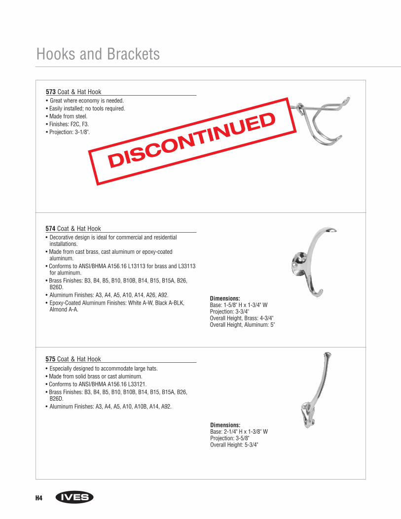
H4
Hooks and Brackets
573 Coat & Hat Hook• Great where economy is needed.• Easily installed; no tools required.• Made from steel.• Finishes: F2C, F3.• Projection: 3-1/8".
Dimensions:Base: 1-5/8" H x 1-3/4" WProjection: 3-3/4"Overall Height, Brass: 4-3/4"Overall Height, Aluminum: 5"
574 Coat & Hat Hook• Decorative design is ideal for commercial and residential
installations.• Made from cast brass, cast aluminum or epoxy-coated
aluminum.• Conforms to ANSI/BHMA A156.16 L13113 for brass and L33113
for aluminum.• Brass Finishes: B3, B4, B5, B10, B10B, B14, B15, B15A, B26,
B26D.• Aluminum Finishes: A3, A4, A5, A10, A14, A26, A92.• Epoxy-Coated Aluminum Finishes: White A-W, Black A-BLK,
Almond A-A.
575 Coat & Hat Hook• Especially designed to accommodate large hats.• Made from solid brass or cast aluminum.• Conforms to ANSI/BHMA A156.16 L33121.• Brass Finishes: B3, B4, B5, B10, B10B, B14, B15, B15A, B26,
B26D.• Aluminum Finishes: A3, A4, A5, A10, A10B, A14, A92.
Dimensions:Base: 2-1/4" H x 1-3/8" WProjection: 3-5/8"Overall Height: 5-3/4"
DISCONTINUED

H5
Hooks and Brackets
580 Ceiling Hook• Ideal for use in closets, attached to underside of shelves, or in
storage lockers.• Made from cast brass or cast aluminum. • Brass Finishes: B3, B4, B5, B10, B10B, B14, B15, B15A, B26,
B26D.• Aluminum Finishes: A3, A4, A5, A10, A14, A92.
581 Wardrobe Hook• Compact hook is perfect where space is limited, such as behind
doors where low profile is needed.• Made from cast brass, cast aluminum or epoxy-coated
aluminum.• Brass Finishes: B3 (B-605), B4, B5, B10, B10B (B-613), B14,
B15 (B-619), B15A (B-620), B19, B26 (B-625), B26D.• Aluminum Finishes: A3, A4, A5, A10, A14, A92.• Epoxy-Coated Aluminum Finishes: White A-W, Black A-BLK,
Almond A-A.
Dimensions:Base, Brass: 7/8" H x 1-15/16" WBase, Aluminum: 1" H x 1-7/8" WProjection: 2-1/4"
Dimensions:Base: 1-1/4" H x 1-1/4" WProjection, Brass: 1-11/16"Projection, Aluminum: 1-5/8"
582 Double Wardrobe Hook• Compact double hook is perfect where space is limited, such as
behind doors where low profile is needed.• Made from cast brass, cast aluminum or epoxy-coated
aluminum.• Brass Finishes: B3 (B-605), B4, B5, B10, B10B (B-613), B14,
B15 (B-619), B15A (B-620), B19, B26 (B-625), B26D.• Aluminum Finishes: A3, A4, A5, A10, A14, A92.• Epoxy-Coated Aluminum Finishes: White A-W, Black A-BLK,
Almond A-A. Dimensions:Base, Brass: 1-1/8" H x 1-1/4" WBase, Aluminum: 1-1/16" H x 1-3/16 WProjection, Brass: 1"Projection, Aluminum: 1-3/32"
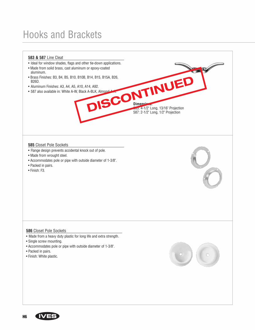
H6
Hooks and Brackets
583 & 587 Line Cleat• Ideal for window shades, flags and other tie-down applications.• Made from solid brass, cast aluminum or epoxy-coated
aluminum.• Brass Finishes: B3, B4, B5, B10, B10B, B14, B15, B15A, B26,
B26D.• Aluminum Finishes: A3, A4, A5, A10, A14, A92.• 587 also available in: White A-W, Black A-BLK, Almond A-A.
Dimensions:583: 4-1/2" Long, 13/16" Projection587: 2-1/2" Long, 1/2" Projection
585 Closet Pole Sockets• Flange design prevents accidental knock out of pole.• Made from wrought steel.• Accommodates pole or pipe with outside diameter of 1-3/8".• Packed in pairs.• Finish: F3.
586 Closet Pole Sockets• Made from a heavy duty plastic for long life and extra strength.• Single screw mounting.• Accommodates pole or pipe with outside diameter of 1-3/8".• Packed in pairs.• Finish: White plastic.
DISCONTINUED

H7
Notes

H8
Notes

Section IWindow Hardware
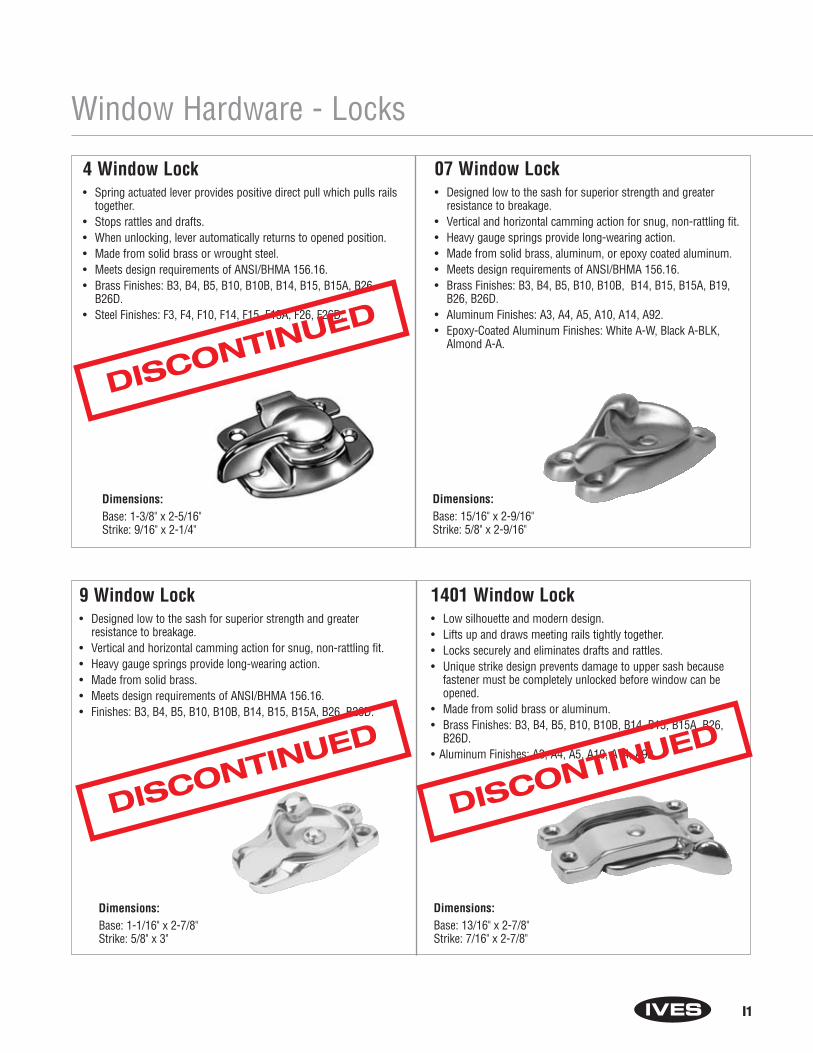
Window Hardware - Locks
4 Window Lock• Spring actuated lever provides positive direct pull which pulls rails
together.• Stops rattles and drafts.• When unlocking, lever automatically returns to opened position.• Made from solid brass or wrought steel.• Meets design requirements of ANSI/BHMA 156.16.• Brass Finishes: B3, B4, B5, B10, B10B, B14, B15, B15A, B26,
B26D.• Steel Finishes: F3, F4, F10, F14, F15, F15A, F26, F26D.
Dimensions:Base: 1-3/8" x 2-5/16" Strike: 9/16" x 2-1/4"
07 Window Lock• Designed low to the sash for superior strength and greater
resistance to breakage.• Vertical and horizontal camming action for snug, non-rattling fit.• Heavy gauge springs provide long-wearing action.• Made from solid brass, aluminum, or epoxy coated aluminum.• Meets design requirements of ANSI/BHMA 156.16.• Brass Finishes: B3, B4, B5, B10, B10B, B14, B15, B15A, B19,
B26, B26D.• Aluminum Finishes: A3, A4, A5, A10, A14, A92.• Epoxy-Coated Aluminum Finishes: White A-W, Black A-BLK,
Almond A-A.
Dimensions:Base: 15/16" x 2-9/16" Strike: 5/8" x 2-9/16"
9 Window Lock• Designed low to the sash for superior strength and greater
resistance to breakage.• Vertical and horizontal camming action for snug, non-rattling fit.• Heavy gauge springs provide long-wearing action.• Made from solid brass.• Meets design requirements of ANSI/BHMA 156.16.• Finishes: B3, B4, B5, B10, B10B, B14, B15, B15A, B26, B26D.
1401 Window Lock• Low silhouette and modern design.• Lifts up and draws meeting rails tightly together.• Locks securely and eliminates drafts and rattles.• Unique strike design prevents damage to upper sash because
fastener must be completely unlocked before window can be opened.
• Made from solid brass or aluminum.• Brass Finishes: B3, B4, B5, B10, B10B, B14, B15, B15A, B26,
B26D.• Aluminum Finishes: A3, A4, A5, A10, A14, A92.
Dimensions:Base: 1-1/16" x 2-7/8" Strike: 5/8" x 3"
Dimensions:Base: 13/16" x 2-7/8" Strike: 7/16" x 2-7/8"
I1
DISCONTINUED
DISCONTINUED
DISCONTINUED

Window Hardware - Locks
0 Open Window Lock• For locking double hung windows in open position.• Window unit may be left open at top or bottom or both top and
bottom.• Ideal for use where air conditioning unit or fan is used.• Made from wrought steel.• Meets ANSI/BHMA 156.16.• Finish: F3.
90 Side Window Lock• May be used singularly for small windows or in pairs for large
windows.• Cam action eliminates rattles and holds window firmly in desired
position.• Made from aluminum.• Finish: A3.
Dimensions:Plate: 1-9/16" x 1-3/8"Projection: 5/8" Strike: 1" x 3/4"
Dimensions:
Size: 1-3/4" x 1-1/8"
I2
DISCONTINUED
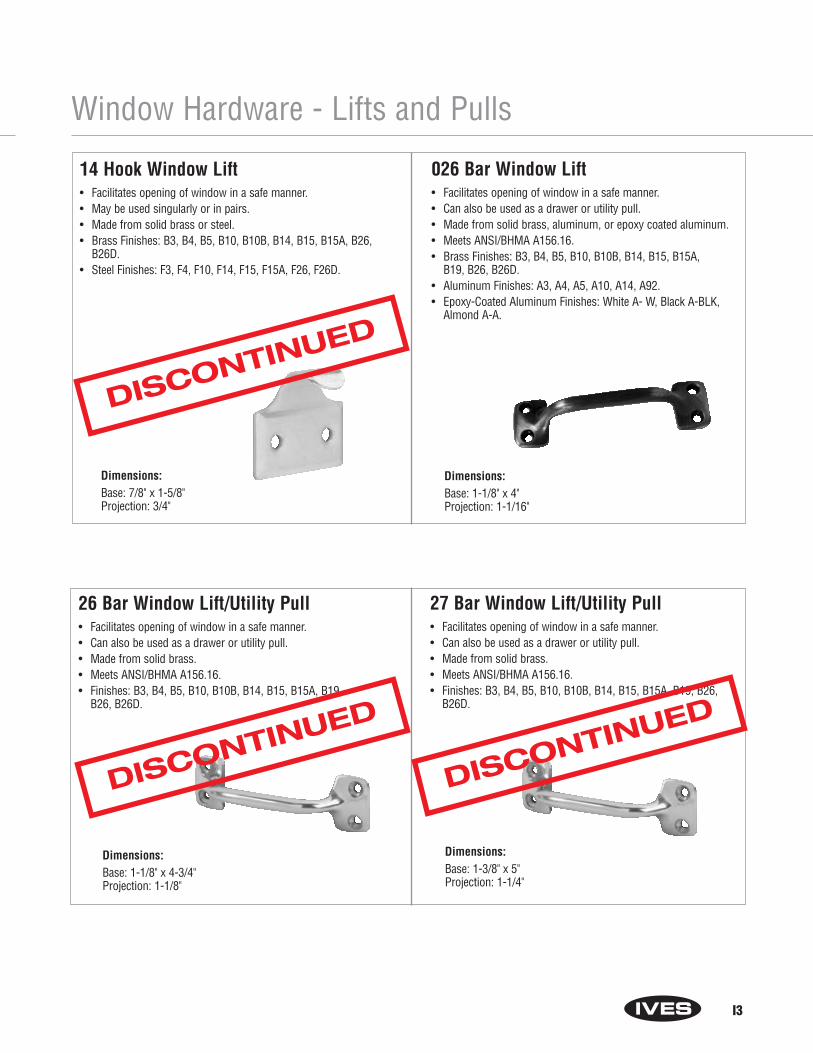
Window Hardware - Lifts and Pulls
14 Hook Window Lift• Facilitates opening of window in a safe manner.• May be used singularly or in pairs.• Made from solid brass or steel.• Brass Finishes: B3, B4, B5, B10, B10B, B14, B15, B15A, B26,
B26D.• Steel Finishes: F3, F4, F10, F14, F15, F15A, F26, F26D.
026 Bar Window Lift• Facilitates opening of window in a safe manner.• Can also be used as a drawer or utility pull.• Made from solid brass, aluminum, or epoxy coated aluminum.• Meets ANSI/BHMA A156.16. • Brass Finishes: B3, B4, B5, B10, B10B, B14, B15, B15A,
B19, B26, B26D.• Aluminum Finishes: A3, A4, A5, A10, A14, A92.• Epoxy-Coated Aluminum Finishes: White A- W, Black A-BLK,
Almond A-A.
Dimensions:Base: 7/8" x 1-5/8"Projection: 3/4"
Dimensions:Base: 1-1/8" x 4"Projection: 1-1/16"
26 Bar Window Lift/Utility Pull• Facilitates opening of window in a safe manner.• Can also be used as a drawer or utility pull.• Made from solid brass.• Meets ANSI/BHMA A156.16. • Finishes: B3, B4, B5, B10, B10B, B14, B15, B15A, B19,
B26, B26D.
Dimensions:Base: 1-1/8" x 4-3/4"Projection: 1-1/8"
27 Bar Window Lift/Utility Pull• Facilitates opening of window in a safe manner.• Can also be used as a drawer or utility pull.• Made from solid brass.• Meets ANSI/BHMA A156.16. • Finishes: B3, B4, B5, B10, B10B, B14, B15, B15A, B19, B26,
B26D.
Dimensions:Base: 1-3/8" x 5"Projection: 1-1/4"
I3
DISCONTINUED
DISCONTINUED
DISCONTINUED
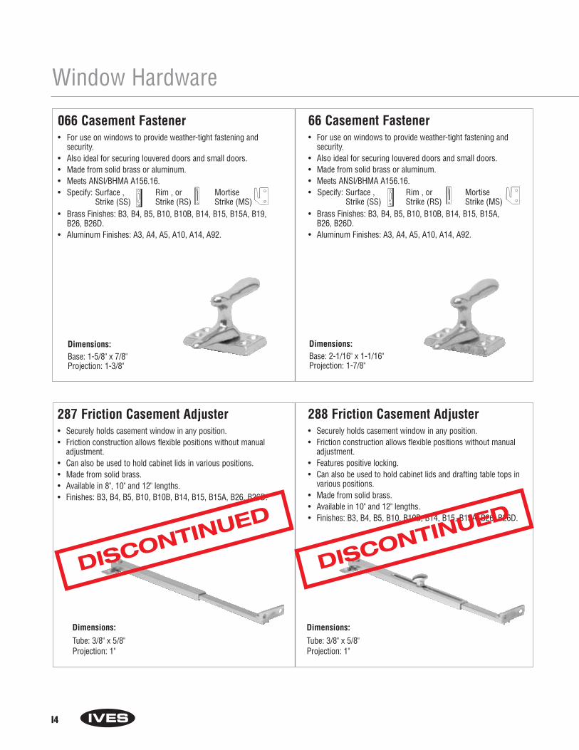
Window Hardware
066 Casement Fastener• For use on windows to provide weather-tight fastening and
security.• Also ideal for securing louvered doors and small doors.• Made from solid brass or aluminum.• Meets ANSI/BHMA A156.16.• Specify: Surface , Rim , or Mortise
Strike (SS) Strike (RS) Strike (MS)• Brass Finishes: B3, B4, B5, B10, B10B, B14, B15, B15A, B19,
B26, B26D.• Aluminum Finishes: A3, A4, A5, A10, A14, A92.
Dimensions:Base: 1-5/8" x 7/8"Projection: 1-3/8"
66 Casement Fastener• For use on windows to provide weather-tight fastening and
security.• Also ideal for securing louvered doors and small doors.• Made from solid brass or aluminum.• Meets ANSI/BHMA A156.16. • Specify: Surface , Rim , or Mortise
Strike (SS) Strike (RS) Strike (MS)• Brass Finishes: B3, B4, B5, B10, B10B, B14, B15, B15A,
B26, B26D. • Aluminum Finishes: A3, A4, A5, A10, A14, A92.
Dimensions:Base: 2-1/16" x 1-1/16"Projection: 1-7/8"
287 Friction Casement Adjuster• Securely holds casement window in any position.• Friction construction allows flexible positions without manual
adjustment.• Can also be used to hold cabinet lids in various positions.• Made from solid brass.• Available in 8", 10" and 12" lengths.• Finishes: B3, B4, B5, B10, B10B, B14, B15, B15A, B26, B26D.
Dimensions:
Tube: 3/8" x 5/8"Projection: 1"
288 Friction Casement Adjuster• Securely holds casement window in any position.• Friction construction allows flexible positions without manual
adjustment.• Features positive locking.• Can also be used to hold cabinet lids and drafting table tops in
various positions.• Made from solid brass. • Available in 10" and 12" lengths.• Finishes: B3, B4, B5, B10, B10B, B14, B15, B15A, B26, B26D.
Dimensions:
Tube: 3/8" x 5/8"Projection: 1"
I4
DISCONTINUED
DISCONTINUED

Window Hardware31 Shutter Bars• Ideal for bi-fold doors and shutters.• Shoulder rivet insures free swinging bar.• Convex styling of bar for better finger grip and convenient operation.• Made from cast brass. • Packed with brass oval head screws.• Finishes: B3, B4, B5, B10, B10B, B14, B15, B15A, B26, B26D.
71 Casement Adjuster• Securely holds casement window in any position.• Can also be used to hold cabinet lids and drafting table tops in
various positions.• Made from burnished steel or solid brass. • Available in 10" and 12" lengths.• Finishes: B3, F3, F4, F5, F10, F14.
Dimensions:Base: 7/8" x 1-1/2"Hook Centers: 1-3/8"Projection: 7/16"
Dimensions:Tube: 3/8" x 5/8"Projection: 1"Sash Plate:Brass: 1-5/8" x 5/8"Steel: 2 x 5/8"
Sill Plate:2-1/4" x 15/16"
80 Transom Catch• Independent latch action; transom can be closed by pushing
directly on ring.• Reversible: latch bolt can be easily reversed by removing back plate.• Narrow base accommodates 1-1/4" rail.• Made from cast brass or cast aluminum.• When ordering, specify Universal Strike (US) or Rim Strike (RS).• Conforms to design requirements of ANSI/BHMA A156.16.• Finishes: B3, B4, B5, B10, B10B, B14, B15, B15A, B26, B26D, A3,
A4, A5, A10, A14, A92.
82 Transom Chain• Available in 10", 12" and 15" chain lengths to meet varying opening
requirements and transom sizes.• Made from wrought steel.• Plate Size: 1-1/2" x 1".• Finishes: F3, F4, F10, F14, F26D.
Dimensions:Size: 2-1/4" x 1-1/4"Latch Throw: 5/16" Universal Strike Shown
I5
DISCONTINUED
DISCONTINUED
DISCONTINUED
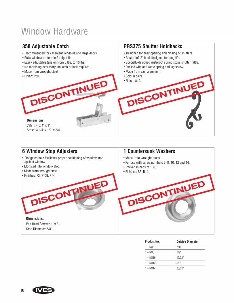
Window Hardware350 Adjustable Catch• Recommended for casement windows and large doors.• Pulls window or door in for tight fit.• Easily adjustable tension from 5 lbs. to 10 lbs.• No mortising necessary; no latch or lock required.• Made from wrought steel.• Finish: F2C.
PRS375 Shutter Holdbacks• Designed for easy opening and closing of shutters.• Rustproof "S" hook designed for long life.• Specially-designed rustproof spring stops shutter rattle.• Packed with anti-rattle spring and lag screw.• Made from cast aluminum.• Sold in pairs. • Finish: A19.
Dimensions:Catch: 4" x 1" x 1"Strike: 3-3/4" x 1/2" x 3/4"
6 Window Stop Adjusters• Elongated hole facilitates proper positioning of window stop
against window.• Mortised into window stop.• Made from wrought steel.• Finishes: F3, F10B, F14.
Dimensions:
Pan Head Screws: 1" x 8Stop Diameter: 5/8"
1 Countersunk Washers• Made from wrought brass.• For use with screw numbers 6, 8, 10, 12 and 14.• Packed in bags of 100.• Finishes: B3, B14.
Product No. Outside Diameter
1 – NO6 7/16"
1 – NO8 1/2"
1 – NO10 19/32"
1 – NO12 5/8"
1 – NO14 25/32"
I6
DISCONTINUED
DISCONTINUED
DISCONTINUED
DISCONTINUED

I7
Notes

I8
Notes
Section JHinges
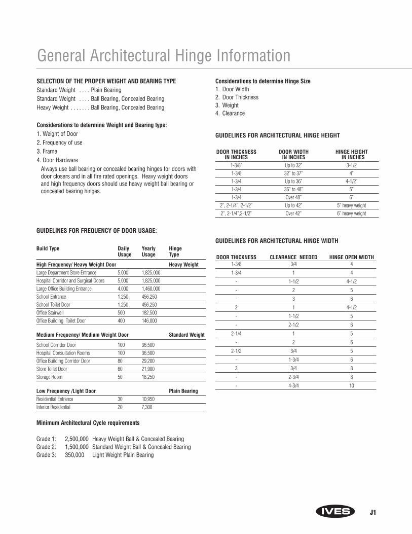
J1
General Architectural Hinge InformationSELECTION OF THE PROPER WEIGHT AND BEARING TYPEStandard Weight . . . . Plain BearingStandard Weight . . . . Ball Bearing, Concealed BearingHeavy Weight . . . . . . . Ball Bearing, Concealed Bearing
Considerations to determine Weight and Bearing type:1. Weight of Door2. Frequency of use3. Frame4. Door Hardware
Always use ball bearing or concealed bearing hinges for doors withdoor closers and in all fire rated openings. Heavy weight doorsand high frequency doors should use heavy weight ball bearing orconcealed bearing hinges.
GUIDELINES FOR FREQUENCY OF DOOR USAGE:
Build Type Daily Yearly HingeUsage Usage Type
High Frequency/ Heavy Weight Door Heavy WeightLarge Department Store Entrance 5,000 1,825,000Hospital Corridor and Surgical Doors 5,000 1,825,000Large Office Building Entrance 4,000 1,460,000School Entrance 1,250 456,250School Toilet Door 1,250 456,250Office Stairwell 500 182,500Office Building Toilet Door 400 146,000
Medium Frequency/ Medium Weight Door Standard Weight
School Corridor Door 100 36,500Hospital Consultation Rooms 100 36,500Office Building Corridor Door 80 29,200Store Toilet Door 60 21,900Storage Room 50 18,250
Low Frequency /Light Door Plain BearingResidential Entrance 30 10,950Interior Residential 20 7,300
Minimum Architectural Cycle requirements
Grade 1: 2,500,000 Heavy Weight Ball & Concealed BearingGrade 2: 1,500,000 Standard Weight Ball & Concealed BearingGrade 3: 350,000 Light Weight Plain Bearing
Considerations to determine Hinge Size1. Door Width2. Door Thickness3. Weight4. Clearance
GUIDELINES FOR ARCHITECTURAL HINGE HEIGHT
DOOR THICKNESS DOOR WIDTH HINGE HEIGHTIN INCHES IN INCHES IN INCHES
1-3/8” Up to 32” 3-1/21-3/8 32” to 37” 4”1-3/4 Up to 36” 4-1/2”1-3/4 36” to 48” 5”1-3/4 Over 48” 6”
2”, 2-1/4”, 2-1/2” Up to 42” 5” heavy weight2”, 2-1/4”,2-1/2” Over 42” 6” heavy weight
GUIDELINES FOR ARCHITECTURAL HINGE WIDTH
DOOR THICKNESS CLEARANCE NEEDED HINGE OPEN WIDTH 1-3/8 3/4 4
1-3/4 1 4
- 1-1/2 4-1/2
- 2 5
- 3 6
2 1 4-1/2
- 1-1/2 5
- 2-1/2 6
2-1/4 1 5
- 2 6
2-1/2 3/4 5
- 1-3/4 6
3 3/4 8
- 2-3/4 8
- 4-3/4 10

J2
GUIDELINES FOR NUMBER OF ARCHITECTURAL HINGES1. Doors up to 60”…… 2 hinges2. Doors 60" to 90".….. 3 hinges3. Doors 90" to 120" …. 4 hinges
LOCATION OF ARCHITECTURAL HINGES
GUIDELINES FOR ARCHITECTURAL HINGE METAL
1. Interior doors or non-corrosive areas use: Plated or painted Steel2. Interior labeled door use: Plated or Painted Steel, Stainless Steel3. Interior doors in corrosive areas use: Stainless Steel , Brass, Bronze4. Exterior doors use: Stainless Steel, Brass, Bronze
Top hinge 5" from jambrabbet to top of barrel
Bottom hinge 10" frombottom edge of barrel tofinished floor
Third hinge centeredbetween top and bottomhinges
Note: Certain westernstates use a standard 7"from top and 11"From the bottom
General Architectural Hinge InformationIVES ARCHITECTURAL HINGE FINISHES
B.H.M.A SYMBOLBASE MATERIAL
STEEL BRASS STAINLESS U.S.IVES DESCRIPTION STEEL Equivalent600 Primed for painting 600 USP605 Bright Brass, clear coated 605 US3606 Satin Brass, clear coated 606 US4612 Satin Bronze, clear coated 612 US10613 Oil Rubbed Satin Bronze 613 US10B619 Satin Nickel Plated, 619 US15
clear coated630 Satin Stainless Steel 630 US32D632 Bright Brass Plated, 632 US3
clear coated633 Satin Brass Plated, 633 US4
clear coated639 Satin Bronze Plated, 639 US10
clear coated640 Oil Rubbed Satin Bronze 640 US10B641 Antique Bronze, Plated, 641 US10A
Relieved, clear coated643 Satin Bronze Plated, 643 US11
Blackened646 Satin Nickel Plated, 646 US15
clear coated651 Bright Chromium Plated 651 US26652 Satin Chromium Plated 652 US26D
MODEL NUMBER COMPARISON CHART
TYPE ANSI IVES HAGER MCKINNEY STANLEY BOMMER PBBSTEEL PLAIN BEARING A8133 3PB1 700 T714 8000 CP81STAINLESS PLAIN BEARING A5133 3PB1 800 NA 8002 CP51STEEL CONCEALED BEARING A8112 3CB1 AB700 TA714 LB8000 CB81STAINLESS CONCEALED BEARING A5112 3CB1 AB800 TA314 LB8002 CB51STEEL CONCEALED BEARING HEAVY WEIGHT A8111 3CB1HW AB750 TA786 LB8004 4C81STAINLESS CONCEALED BEARING HEAVY WEIGHT A5111 3CB1HW AB850 TA386 LB8006 4C51BRASS CONCEALED BEARING HEAVY WEIGHT A2111 3CB1HW AB850 TA386 LB8005 4B21STEEL BALL BEARING A8112 5BB1 BB1279 TB2714 FBB179 BB5000 BB81STAINLESS BALL BEARING A5112 5BB1 BB1191 TB2314 FBB191 BB5002 BB51STEEL BALL BEARING HEAVY WEIGHT A8111 5BB1HW BB1168 T4B3786 FBB168 BB5004 4B81STAINLESS BALL BEARING HEAVY WEIGHT A5111 5BB1HW BB1199 T4B3386 FBB199 BB5006 4B51STEEL SWING CLEAR A8122 5BBSC1 BB1260 TB2895 FBB248 BB8020 SC81

How to Order:
Number of Knuckles:3 - 3 Knuckle 5 - 5 Knuckle
Function: PB Plain BearingBB Ball BearingCB Concealed BearingSP Spring Hinge
Type: 1 Full Mortise2 Half/Mortise3 Full Surface4 Half Surface
Weight/Options: Blank Standard WeightHW Heavy WeightSC Swing ClearSH Security StudWT Wide ThrowST High Security StudHT Hospital Tips
Size Examples: 4.5 x 44.5 x 4.55 x 4.5
Finish (Some models are not available in all finishes): 600 USP - Steel605 US3 - Brass606 US4 - Brass612 US10 - Brass613 US10B - Brass619 US15 - Brass630 US32D - Stainless632 US3 - Steel633 US4 - Steel639 US10 - Steel640 US10B - Steel641 US10A - Steel643 US11 - Steel646 US15 - Steel651 US26 - Steel652 US26D - Steel
Special Pins Applications: NRP Non-Removable PinHT Hospital TipTW4 Four WireTW8 Eight WireMON MonitorTW4M Four Wire with MonitorTW8M Eight Wire with Monitor
J3
General Architectural Hinge InformationIves Hinge Number SystemPlease note: For availability of specific models, please refer to the item’s catalog page or consult Customer Service.
____ - ____- ____ - ____- ____ - ____- ____ - ____
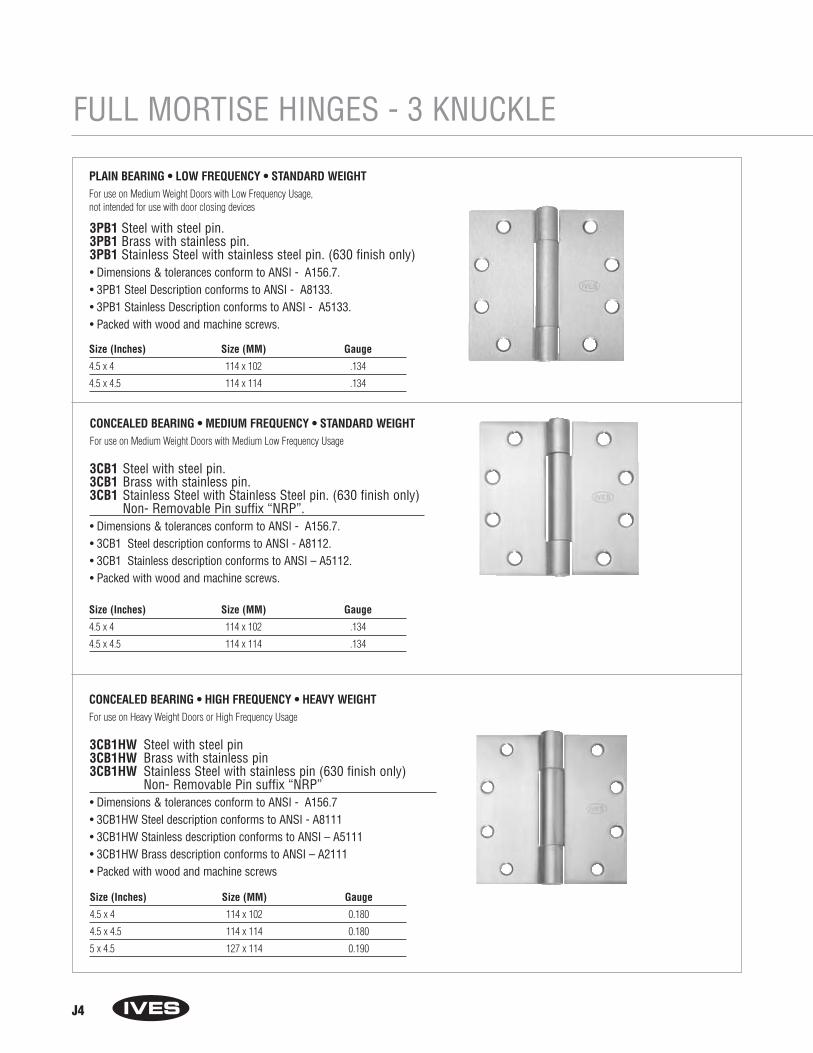
J4
FULL MORTISE HINGES - 3 KNUCKLE
3PB1 Steel with steel pin.3PB1 Brass with stainless pin.3PB1 Stainless Steel with stainless steel pin. (630 finish only)• Dimensions & tolerances conform to ANSI - A156.7.• 3PB1 Steel Description conforms to ANSI - A8133.• 3PB1 Stainless Description conforms to ANSI - A5133.• Packed with wood and machine screws.
Size (Inches) Size (MM) Gauge
4.5 x 4 114 x 102 .134
4.5 x 4.5 114 x 114 .134
PLAIN BEARING • LOW FREQUENCY • STANDARD WEIGHTFor use on Medium Weight Doors with Low Frequency Usage, not intended for use with door closing devices
3CB1 Steel with steel pin.3CB1 Brass with stainless pin.3CB1 Stainless Steel with Stainless Steel pin. (630 finish only)
Non- Removable Pin suffix “NRP”.• Dimensions & tolerances conform to ANSI - A156.7.• 3CB1 Steel description conforms to ANSI - A8112.• 3CB1 Stainless description conforms to ANSI – A5112.• Packed with wood and machine screws.
CONCEALED BEARING • MEDIUM FREQUENCY • STANDARD WEIGHT For use on Medium Weight Doors with Medium Low Frequency Usage
3CB1HW Steel with steel pin3CB1HW Brass with stainless pin3CB1HW Stainless Steel with stainless pin (630 finish only)
Non- Removable Pin suffix “NRP”• Dimensions & tolerances conform to ANSI - A156.7• 3CB1HW Steel description conforms to ANSI - A8111• 3CB1HW Stainless description conforms to ANSI – A5111• 3CB1HW Brass description conforms to ANSI – A2111• Packed with wood and machine screws
CONCEALED BEARING • HIGH FREQUENCY • HEAVY WEIGHT For use on Heavy Weight Doors or High Frequency Usage
Size (Inches) Size (MM) Gauge
4.5 x 4 114 x 102 0.180
4.5 x 4.5 114 x 114 0.180
5 x 4.5 127 x 114 0.190
Size (Inches) Size (MM) Gauge
4.5 x 4 114 x 102 .134
4.5 x 4.5 114 x 114 .134

J5
FULL MORTISE HINGES - 3 KNUCKLE
3SP1 Steel with steel pin3SP1 Stainless Steel with stainless pin (630 finish only)• UL listed for use with fire rated doors. • Packed with wood and machine screws.
SPRING HINGEFor automatic closing of door.
Size (Inches) Size (MM) Gauge
4.5 x 4.5 114 x 114 0.134
5PB1 Steel with steel pin5PB1 Brass with stainless pin5PB1 Stainless Steel with stainless steel pin (630 finish)
Non-Removable Pin Suffix “NRP”• Dimensions & tolerances conform to ANSI - A156.7.• Packed with wood and machine screws.
PLAIN BEARING • LOW FREQUENCY • STANDARD WEIGHT For use on Medium Weight Doors with Low Frequency Usage, not intended for use with door closing devices.
Size (Inches) Size (MM) Gauge
4.5 x 4.5 114 x 114 .134
4.5 x 4 114 x 102 .134
5BB1 Steel with steel pin5BB1 Brass with stainless pin5BB1 Stainless Steel with stainless steel pin (630 finish only)
Non-Removable Pin suffix “NRP”• Dimensions & tolerances conform to ANSI - A156.7.• 5BB1 Steel description conforms to ANSI - A8112.• 5BB1 Stainless description conforms to ANSI – A5112.• Packed with wood and machine screws.
Size (Inches) Size (MM) Gauge
4.5 x 4.5 114 x 114 .134
4.5 x 4 114 x 102 .134
5 x 4.5 127 x 114 .134
2 BALL BEARING • MEDIUM FREQUENCY • STANDARD WEIGHT For use on Standard Weight Doors with Medium Frequency Usage
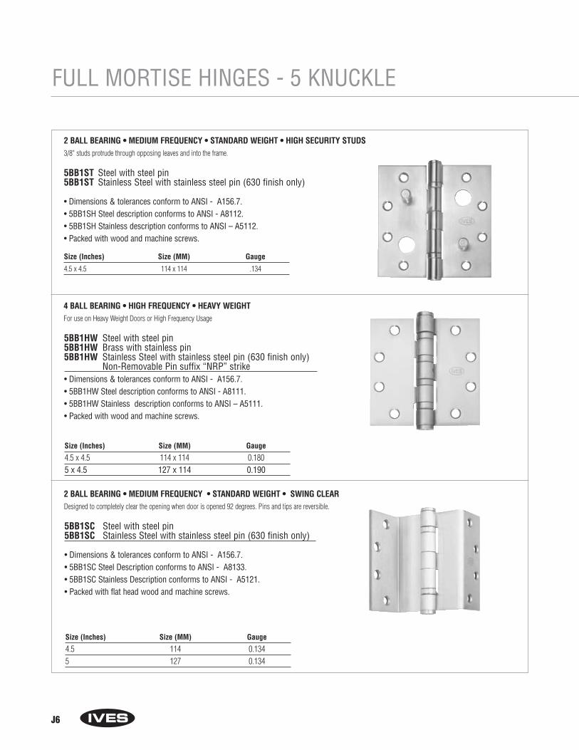
J6
FULL MORTISE HINGES - 5 KNUCKLE
Size (Inches) Size (MM) Gauge
4.5 x 4.5 114 x 114 .134
5BB1ST Steel with steel pin5BB1ST Stainless Steel with stainless steel pin (630 finish only)
• Dimensions & tolerances conform to ANSI - A156.7.• 5BB1SH Steel description conforms to ANSI - A8112.• 5BB1SH Stainless description conforms to ANSI – A5112.• Packed with wood and machine screws.
2 BALL BEARING • MEDIUM FREQUENCY • STANDARD WEIGHT • HIGH SECURITY STUDS3/8" studs protrude through opposing leaves and into the frame.
5BB1HW Steel with steel pin5BB1HW Brass with stainless pin5BB1HW Stainless Steel with stainless steel pin (630 finish only)
Non-Removable Pin suffix “NRP” strike• Dimensions & tolerances conform to ANSI - A156.7.• 5BB1HW Steel description conforms to ANSI - A8111.• 5BB1HW Stainless description conforms to ANSI – A5111.• Packed with wood and machine screws.
4 BALL BEARING • HIGH FREQUENCY • HEAVY WEIGHT For use on Heavy Weight Doors or High Frequency Usage
Size (Inches) Size (MM) Gauge
4.5 x 4.5 114 x 114 0.1805 x 4.5 127 x 114 0.190
5BB1SC Steel with steel pin5BB1SC Stainless Steel with stainless steel pin (630 finish only)
• Dimensions & tolerances conform to ANSI - A156.7.• 5BB1SC Steel Description conforms to ANSI - A8133.• 5BB1SC Stainless Description conforms to ANSI - A5121.• Packed with flat head wood and machine screws.
2 BALL BEARING • MEDIUM FREQUENCY • STANDARD WEIGHT • SWING CLEARDesigned to completely clear the opening when door is opened 92 degrees. Pins and tips are reversible.
Size (Inches) Size (MM) Gauge
4.5 114 0.1345 127 0.134
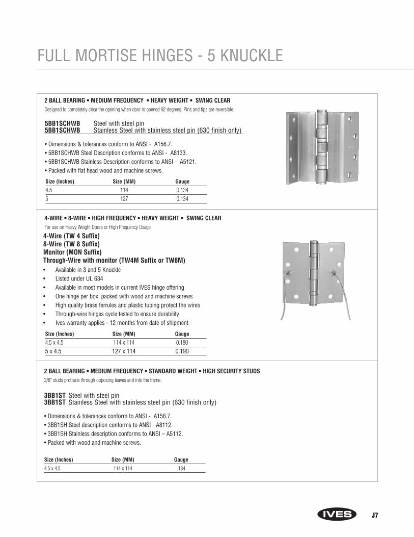
J7
FULL MORTISE HINGES - 5 KNUCKLE
4-Wire (TW 4 Suffix)8-Wire (TW 8 Suffix)Monitor (MON Suffix)Through-Wire with monitor (TW4M Suffix or TW8M)• Available in 3 and 5 Knuckle• Listed under UL 634• Available in most models in current IVES hinge offering• One hinge per box, packed with wood and machine screws• High quality brass ferrules and plastic tubing protect the wires• Through-wire hinges cycle tested to ensure durability• Ives warranty applies - 12 months from date of shipment
4-WIRE • 8-WIRE • HIGH FREQUENCY • HEAVY WEIGHT • SWING CLEARFor use on Heavy Weight Doors or High Frequency Usage
Size (Inches) Size (MM) Gauge
4.5 x 4.5 114 x 114 0.1805 x 4.5 127 x 114 0.190
Size (Inches) Size (MM) Gauge
4.5 x 4.5 114 x 114 .134
3BB1ST Steel with steel pin3BB1ST Stainless Steel with stainless steel pin (630 finish only)
• Dimensions & tolerances conform to ANSI - A156.7.• 3BB1SH Steel description conforms to ANSI - A8112.• 3BB1SH Stainless description conforms to ANSI – A5112.• Packed with wood and machine screws.
2 BALL BEARING • MEDIUM FREQUENCY • STANDARD WEIGHT • HIGH SECURITY STUDS3/8" studs protrude through opposing leaves and into the frame.
5BB1SCHWB Steel with steel pin5BB1SCHWB Stainless Steel with stainless steel pin (630 finish only)
• Dimensions & tolerances conform to ANSI - A156.7.• 5BB1SCHWB Steel Description conforms to ANSI - A8133.• 5BB1SCHWB Stainless Description conforms to ANSI - A5121.• Packed with flat head wood and machine screws.
2 BALL BEARING • MEDIUM FREQUENCY • HEAVY WEIGHT • SWING CLEARDesigned to completely clear the opening when door is opened 92 degrees. Pins and tips are reversible.
Size (Inches) Size (MM) Gauge
4.5 114 0.1345 127 0.134

J8
RESIDENTIAL HINGES
• Full mortise hinges in 3 sizes: 3", 3-1/2" and 4".• Two corner options: Square corner and 5/8" radius corners.• Made from solid brass or stainless steel.• Finishes: B-505 (Ultima Lifetime Anti-Tarnish), B-613, B-619,
B-620 and B-625
1000 Series Residential Hinges
Model Size Corner
1000 3" x 3" Square Corner1001 3" x 3" 5/8" Radius Corner1010 3-1/2" x 3-1/2" Square Corner1011 3-1/2" x 3-1/2" 5/8" Radius Corner1020 4" x 4" Square Corner1021 4" x 4" 5/8" Radius Corner
1000
1001
1010
1011
1020
1021
DISCONTINUED

Section KCabinet/Closet Knobs
and Pulls

K1
Cabinet/Closet Knobs and Pulls
513 Knob Backplate• For use with Ives cabinet knobs 521, 523, 524, 530 and 535.• Available in two diameters: 1-1/2" and 1-3/4". • Provides a finishing touch. Especially useful to cover holes or marks
in replacement or remodeling applications.• Made from wrought brass.• 3/64" thick backplate. (This increases the projection of knob or pull.)• Conforms to ANSI/BHMA A156.9 B22181. • Finishes: B3, B4, B5, B10, B10B, B14, B15, B15A, B19, B26, B26D.
Models: 513 1 1/2IN 513 1 3/4IN
521 Round Knob• Available in four diameters: 3/4", 1", 1-1/4" and 1-1/2".• Made from wrought brass.• Furnished with a No. 8-32 machine screw, 1-1/8" long.• Conforms to ANSI/BHMA A156.9 B22131.• Finishes: B3, B4, B5, B10, B10B, B14, B15, B15A, B19, B26, B26D.
Model & Diameter Projection521 3/4IN 3/4"521 1IN 15/16"521 1 1/4IN 1-1/8"521 1 1/2IN 1-5/16"
523 Colonial Knob• Available in four diameters: 5/8", 1", 1-1/4" and 1-1/2".• Made from wrought brass.• Furnished with a No. 8-32 machine screw.• Conforms to ANSI/BHMA A156.9 B22131.• Finishes: B3, B4, B5, B10, B10B, B14, B15, B15A, B19, B26, B26D.
Model & Diameter Projection Screw Length523 5/8IN 5/8" 1"523 1IN 15/16" 1-1/8"523 1 1/4IN 1" 1-1/8"523 1 1/2IN 1-7/32" 1-1/8"
DISCONTINUED
DISCONTINUED
DISCONTINUED
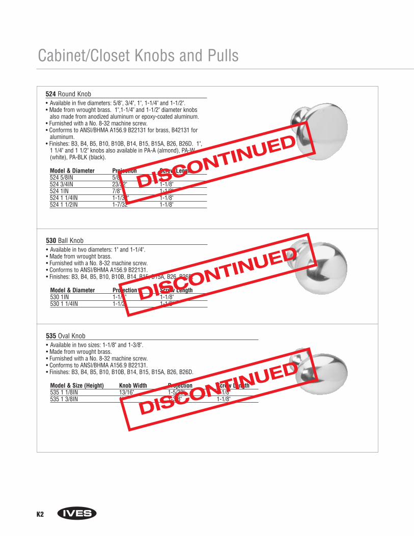
K2
Cabinet/Closet Knobs and Pulls
524 Round Knob• Available in five diameters: 5/8", 3/4", 1", 1-1/4" and 1-1/2".• Made from wrought brass. 1",1-1/4" and 1-1/2" diameter knobs
also made from anodized aluminum or epoxy-coated aluminum.• Furnished with a No. 8-32 machine screw.• Conforms to ANSI/BHMA A156.9 B22131 for brass, B42131 for
aluminum.• Finishes: B3, B4, B5, B10, B10B, B14, B15, B15A, B26, B26D. 1",
1 1/4" and 1 1/2" knobs also available in PA-A (almond), PA-W(white), PA-BLK (black).
Model & Diameter Projection Screw Length524 5/8IN 5/8" 1"524 3/4IN 23/32" 1-1/8"524 1IN 7/8" 1-1/8"524 1 1/4IN 1-1/32" 1-1/8"524 1 1/2IN 1-7/32" 1-1/8"
530 Ball Knob• Available in two diameters: 1" and 1-1/4". • Made from wrought brass.• Furnished with a No. 8-32 machine screw.• Conforms to ANSI/BHMA A156.9 B22131.• Finishes: B3, B4, B5, B10, B10B, B14, B15, B15A, B26, B26D.
Model & Diameter Projection Screw Length530 1IN 1-1/4" 1-1/8"530 1 1/4IN 1-1/2" 1-1/8"
535 Oval Knob• Available in two sizes: 1-1/8" and 1-3/8". • Made from wrought brass.• Furnished with a No. 8-32 machine screw.• Conforms to ANSI/BHMA A156.9 B22131.• Finishes: B3, B4, B5, B10, B10B, B14, B15, B15A, B26, B26D.
Model & Size (Height) Knob Width Projection Screw Length535 1 1/8IN 13/16" 1-5/32" 1-1/8"535 1 3/8IN 1" 1-3/8" 1-1/8"
DISCONTINUED
DISCONTINUED
DISCONTINUED
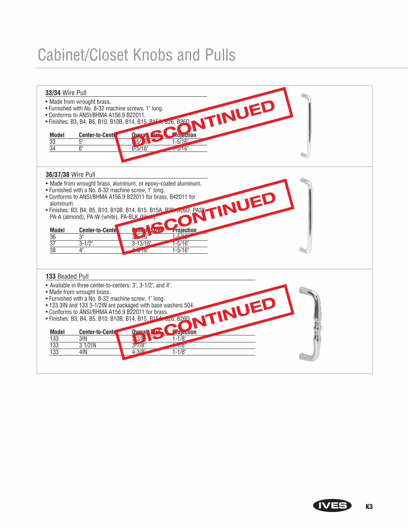
K3
Cabinet/Closet Knobs and Pulls
33/34 Wire Pull• Made from wrought brass.• Furnished with No. 8-32 machine screws, 1" long.• Conforms to ANSI/BHMA A156.9 B22011. • Finishes: B3, B4, B5, B10, B10B, B14, B15, B15A, B26, B26D.
Model Center-to-Center Overall Size Projection33 5" 5-5/16" 1-5/16"34 6" 6-5/16" 1-5/16"
36/37/38 Wire Pull• Made from wrought brass, aluminum, or epoxy-coated aluminum.• Furnished with a No. 8-32 machine screw, 1" long.• Conforms to ANSI/BHMA A156.9 B22011 for brass, B42011 for
aluminum.• Finishes: B3, B4, B5, B10, B10B, B14, B15, B15A, B26, B26D, PA28,
PA-A (almond), PA-W (white), PA-BLK (black).
Model Center-to-Center Overall Size Projection36 3" 3-5/16" 1-5/16"37 3-1/2" 3-13/16" 1-5/16"38 4" 4-5/16" 1-5/16"
133 Beaded Pull• Available in three center-to-centers: 3", 3-1/2", and 4".• Made from wrought brass.• Furnished with a No. 8-32 machine screw, 1" long.• 133 3IN and 133 3-1/2IN are packaged with base washers 504.• Conforms to ANSI/BHMA A156.9 B22011 for brass.• Finishes: B3, B4, B5, B10, B10B, B14, B15, B15A, B26, B26D.
Model Center-to-Center Overall Size Projection133 3IN 3-3/8" 1-1/8"133 3 1/2IN 3-7/8" 1-1/8"133 4IN 4-3/8" 1-1/8"
DISCONTINUED
DISCONTINUED
DISCONTINUED
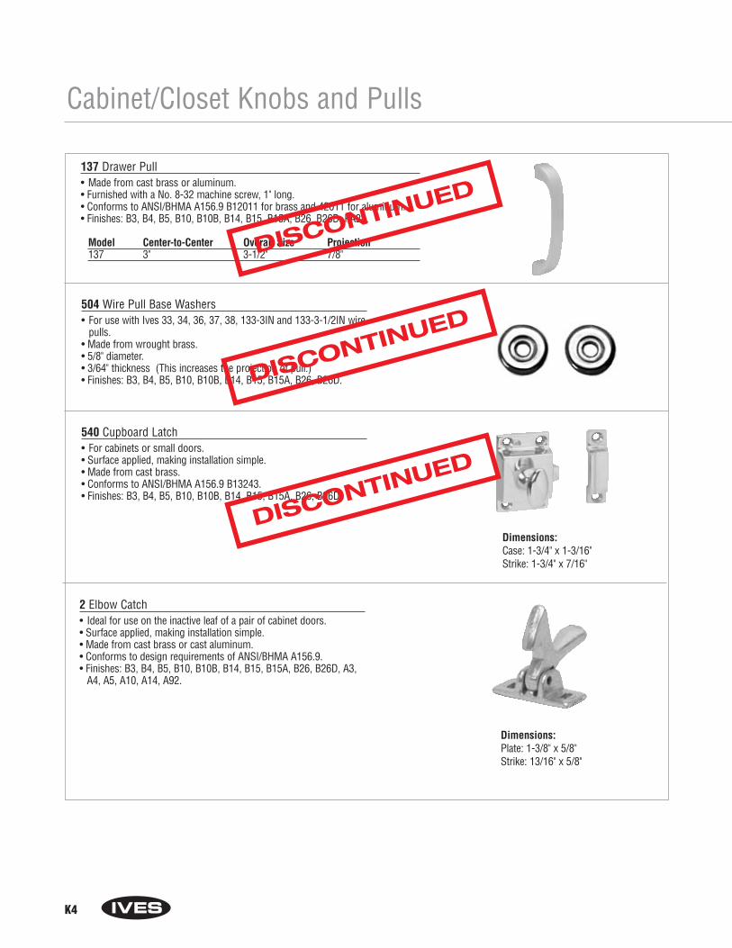
K4
Cabinet/Closet Knobs and Pulls
137 Drawer Pull• Made from cast brass or aluminum.• Furnished with a No. 8-32 machine screw, 1" long.• Conforms to ANSI/BHMA A156.9 B12011 for brass and 42011 for aluminum.• Finishes: B3, B4, B5, B10, B10B, B14, B15, B15A, B26, B26D, PA28.
Model Center-to-Center Overall Size Projection137 3" 3-1/2" 7/8"
504 Wire Pull Base Washers• For use with Ives 33, 34, 36, 37, 38, 133-3IN and 133-3-1/2IN wire
pulls.• Made from wrought brass.• 5/8" diameter.• 3/64" thickness (This increases the projection of pull.)• Finishes: B3, B4, B5, B10, B10B, B14, B15, B15A, B26, B26D.
540 Cupboard Latch• For cabinets or small doors.• Surface applied, making installation simple.• Made from cast brass.• Conforms to ANSI/BHMA A156.9 B13243.• Finishes: B3, B4, B5, B10, B10B, B14, B15, B15A, B26, B26D.
Dimensions:Case: 1-3/4" x 1-3/16"Strike: 1-3/4" x 7/16"
2 Elbow Catch• Ideal for use on the inactive leaf of a pair of cabinet doors.• Surface applied, making installation simple.• Made from cast brass or cast aluminum.• Conforms to design requirements of ANSI/BHMA A156.9.• Finishes: B3, B4, B5, B10, B10B, B14, B15, B15A, B26, B26D, A3,
A4, A5, A10, A14, A92.
Dimensions:Plate: 1-3/8" x 5/8" Strike: 13/16" x 5/8"
DISCONTINUED
DISCONTINUED
DISCONTINUED
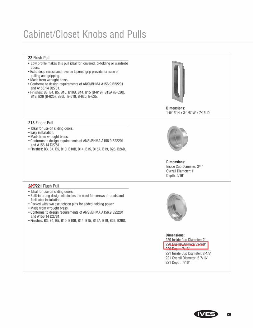
K5
Cabinet/Closet Knobs and Pulls
22 Flush Pull• Low profile makes this pull ideal for louvered, bi-folding or wardrobe
doors.• Extra deep recess and reverse tapered grip provide for ease of
pulling and gripping. • Made from wrought brass.• Conforms to design requirements of ANSI/BHMA A156.9 B22201
and A156.14 D2781.• Finishes: B3, B4, B5, B10, B10B, B14, B15 (B-619), B15A (B-620),
B19, B26 (B-625), B26D, B-619, B-620, B-625.
218 Finger Pull• Ideal for use on sliding doors.• Easy installation.• Made from wrought brass.• Conforms to design requirements of ANSI/BHMA A156.9 B22201
and A156.14 D2781.• Finishes: B3, B4, B5, B10, B10B, B14, B15, B15A, B19, B26, B26D.
220/221 Flush Pull• Ideal for use on sliding doors.• Built-in prong design eliminates the need for screws or brads and
facilitates installation. • Packed with two escutcheon pins for added holding power.• Made from wrought brass.• Conforms to design requirements of ANSI/BHMA A156.9 B22201
and A156.14 D2781.• Finishes: B3, B4, B5, B10, B10B, B14, B15, B15A, B19, B26, B26D.
Dimensions:1-5/16" H x 3-1/8" W x 7/16" D
Dimensions:Inside Cup Diameter: 3/4"Overall Diameter: 1"Depth: 5/16"
Dimensions:220 Inside Cup Diameter: 2"220 Overall Diameter: 2-3/8"220 Depth: 7/16" 221 Inside Cup Diameter: 2-1/8"221 Overall Diameter: 2-7/16"221 Depth: 7/16"
DISCONTINUED
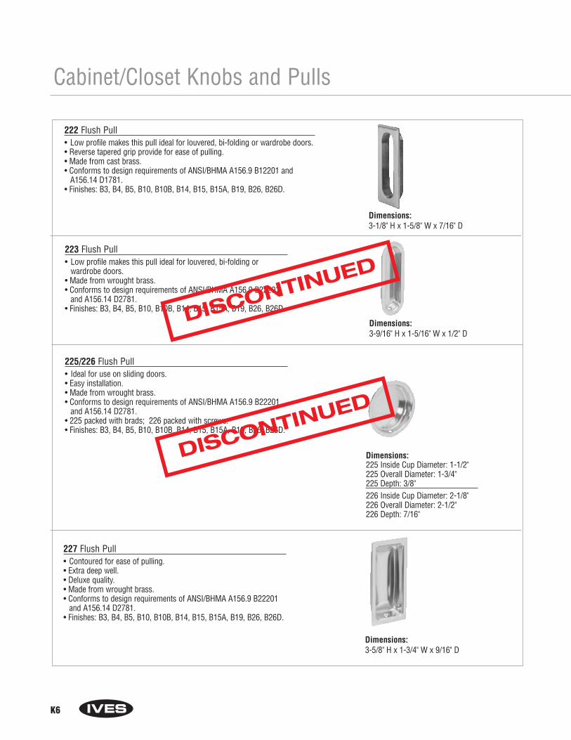
K6
Cabinet/Closet Knobs and Pulls
222 Flush Pull• Low profile makes this pull ideal for louvered, bi-folding or wardrobe doors.• Reverse tapered grip provide for ease of pulling. • Made from cast brass.• Conforms to design requirements of ANSI/BHMA A156.9 B12201 and
A156.14 D1781.• Finishes: B3, B4, B5, B10, B10B, B14, B15, B15A, B19, B26, B26D.
223 Flush Pull• Low profile makes this pull ideal for louvered, bi-folding or
wardrobe doors. • Made from wrought brass.• Conforms to design requirements of ANSI/BHMA A156.9 B22201
and A156.14 D2781.• Finishes: B3, B4, B5, B10, B10B, B14, B15, B15A, B19, B26, B26D.
225/226 Flush Pull• Ideal for use on sliding doors.• Easy installation.• Made from wrought brass.• Conforms to design requirements of ANSI/BHMA A156.9 B22201
and A156.14 D2781.• 225 packed with brads; 226 packed with screws.• Finishes: B3, B4, B5, B10, B10B, B14, B15, B15A, B19, B26, B26D.
Dimensions:225 Inside Cup Diameter: 1-1/2"225 Overall Diameter: 1-3/4"225 Depth: 3/8" 226 Inside Cup Diameter: 2-1/8"226 Overall Diameter: 2-1/2"226 Depth: 7/16"
227 Flush Pull• Contoured for ease of pulling.• Extra deep well.• Deluxe quality. • Made from wrought brass.• Conforms to design requirements of ANSI/BHMA A156.9 B22201
and A156.14 D2781.• Finishes: B3, B4, B5, B10, B10B, B14, B15, B15A, B19, B26, B26D.
Dimensions:3-5/8" H x 1-3/4" W x 9/16" D
Dimensions:3-1/8" H x 1-5/8" W x 7/16" D
Dimensions:3-9/16" H x 1-5/16" W x 1/2" D
DISCONTINUED
DISCONTINUED

K7
Cabinet/Closet Knobs and Pulls
425/426 Flush Ring Pull• Ideal for use on sliding doors.• Convenient finger grip provides easy use of pull.• Made from wrought brass.• Conforms to design requirements of ANSI/BHMA A156.9 B22201.• Finishes: B3, B4, B5, B10, B10B, B14, B15, B15A, B19, B26, B26D.
42 Pocket Sliding Door Bolt• Exclusive Ives design permits emergency release of bolt from outside the
door.• Spring activated design allows feather-touch action.• Brass grommet supplied to cap release hole, protecting the door’s finish.• Made from wrought brass.• Finishes: B3, B4, B5, B10, B10B, B14, B15, B15A, B19, B26, B26D.
230 Sliding Door Edge Pull• 3/4" width allows installation on narrow as well as standard doors.• Spring automatically returns lever flush with plate.• Made from solid brass.• Conforms to design requirements of ANSI/BHMA A156.14 D2801.• Finishes: B3, B4, B5, B10, B10B, B14, B15, B15A, B19, B26, B26D.
Dimensions:425 Inside Cup Diameter: 1-1/2"425 Overall Diameter: 1-3/4"425 Depth: 3/8" 426 Inside Cup Diameter: 2-1/8"426 Overall Diameter: 2-1/2"426 Depth: 3/8"
Dimensions:Overall Size, Plate: 3-1/16" x 1-5/32"Strike: 1" x 3/4"Depth of Mortise: 5/8"
Dimensions:3-7/8" H x 3/4" W
DISCONTINUED
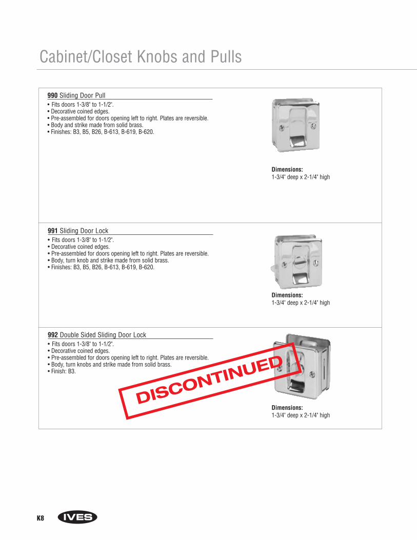
K8
Cabinet/Closet Knobs and Pulls
990 Sliding Door Pull• Fits doors 1-3/8" to 1-1/2".• Decorative coined edges.• Pre-assembled for doors opening left to right. Plates are reversible.• Body and strike made from solid brass.• Finishes: B3, B5, B26, B-613, B-619, B-620.
991 Sliding Door Lock• Fits doors 1-3/8" to 1-1/2".• Decorative coined edges.• Pre-assembled for doors opening left to right. Plates are reversible.• Body, turn knob and strike made from solid brass.• Finishes: B3, B5, B26, B-613, B-619, B-620.
992 Double Sided Sliding Door Lock• Fits doors 1-3/8" to 1-1/2".• Decorative coined edges.• Pre-assembled for doors opening left to right. Plates are reversible.• Body, turn knobs and strike made from solid brass.• Finish: B3.
Dimensions:1-3/4" deep x 2-1/4" high
Dimensions:1-3/4" deep x 2-1/4" high
Dimensions:1-3/4" deep x 2-1/4" high
DISCONTINUED
Section LHobby Hardware
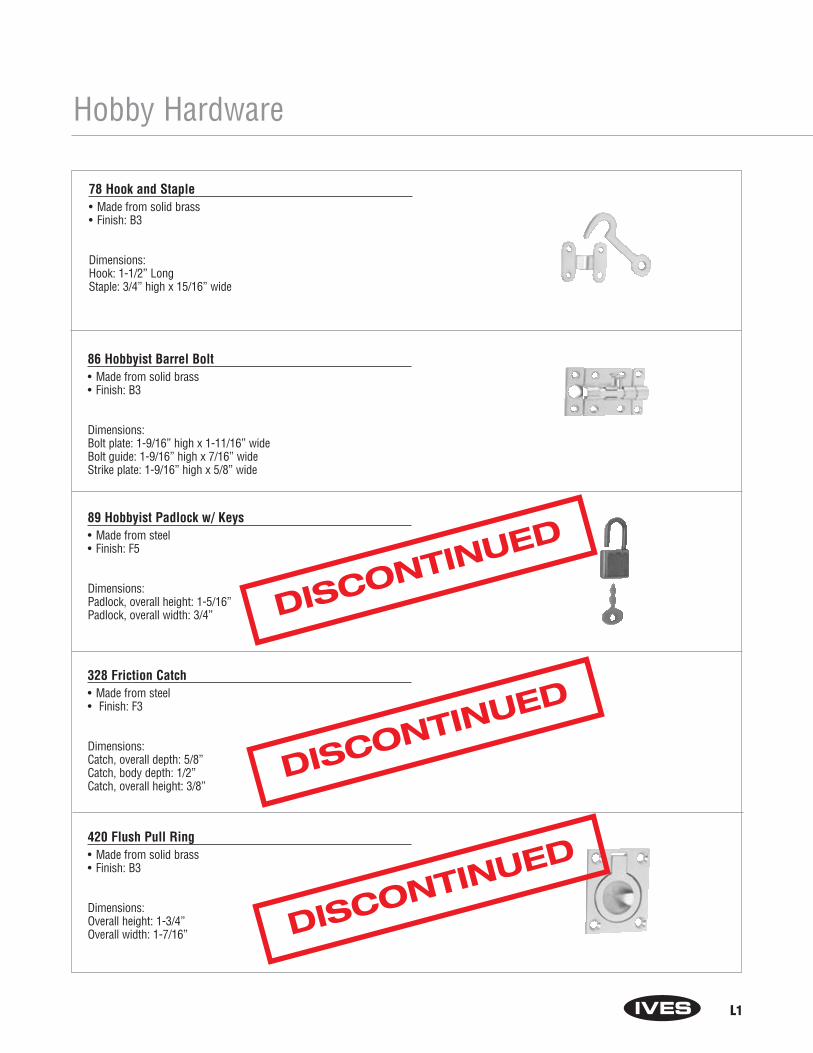
L1
Hobby Hardware
78 Hook and Staple• Made from solid brass• Finish: B3
Dimensions:Hook: 1-1/2” LongStaple: 3/4” high x 15/16” wide
86 Hobbyist Barrel Bolt• Made from solid brass• Finish: B3
Dimensions:Bolt plate: 1-9/16” high x 1-11/16” wideBolt guide: 1-9/16” high x 7/16” wideStrike plate: 1-9/16” high x 5/8” wide
89 Hobbyist Padlock w/ Keys• Made from steel• Finish: F5
Dimensions:Padlock, overall height: 1-5/16”Padlock, overall width: 3/4”
328 Friction Catch• Made from steel• Finish: F3
Dimensions:Catch, overall depth: 5/8”Catch, body depth: 1/2”Catch, overall height: 3/8”
420 Flush Pull Ring• Made from solid brass• Finish: B3
Dimensions:Overall height: 1-3/4”Overall width: 1-7/16”
DISCONTINUED
DISCONTINUED
DISCONTINUED

L2
Hobby Hardware
520 Cabinet Knob• Made from solid brass• Finish: B3
Dimensions:Projection: 3/8”Diameter: 1/2”
690 Continuous Hinge• Made from solid brass• Finish: B3
Dimensions:Overall height: 4”Overall width: 3/4”
691 Continuous Hinges• Made from solid brass• Finish: B3
Dimensions:Overall height: 8 “Overall width: 3/4”
9010 Narrow Butt Hinge9020 Narrow Butt Hinge9030 Narrow Butt Hinge• Made from solid brass• Finish: B3
Dimensions:9010 Overall height x overall width: 3/4” x 5/8”9020 Overall height x overall width: 1” x 3/4”9030 Overall height x overall width: 1-1/2” x 15/16”
9040 Narrow Butt Hinge• Made from solid brass• Finish: B3
Dimensions:Overall height x overall width: 2” x 1”
DISCONTINUED
DISCONTINUED
DISCONTINUED
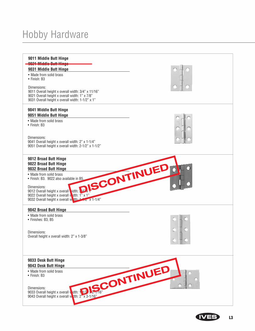
L3
Hobby Hardware
9011 Middle Butt Hinge9021 Middle Butt Hinge9031 Middle Butt Hinge• Made from solid brass• Finish: B3
Dimensions:9011 Overall height x overall width: 3/4” x 11/16”9021 Overall height x overall width: 1” x 7/8”9031 Overall height x overall width: 1-1/2” x 1”
9041 Middle Butt Hinge9051 Middle Butt Hinge• Made from solid brass• Finish: B3
Dimensions:9041 Overall height x overall width: 2” x 1-1/4”9051 Overall height x overall width: 2-1/2” x 1-1/2”
9012 Broad Butt Hinge9022 Broad Butt Hinge9032 Broad Butt Hinge• Made from solid brass• Finish: B3. 9022 also available in B5.
Dimensions:9012 Overall height x overall width: 3/4” x 1”9022 Overall height x overall width: 1” x 1”9032 Overall height x overall width: 1-1/2” x 1-1/4”
9042 Broad Butt Hinge• Made from solid brass• Finishes: B3, B5
Dimensions:Overall height x overall width: 2” x 1-3/8”
9033 Desk Butt Hinge9043 Desk Butt Hinge• Made from solid brass• Finish: B3
Dimensions:9033 Overall height x overall width: 1-1/2” x 2-1/16”9043 Overall height x overall width: 2” x 3-1/16”
DISCONTINUED
DISCONTINUED

L4
Hobby Hardware
9060 Decorative Hinge• Made from solid brass• Finishes: B3, B5
Dimensions:Overall height x overall width: 5/8” x 1”
9061 Decorative Hinge• Made from solid brass• Finish: B3
Dimensions:Overall height x overall width: 3/4” x 1-7/8”
9070 Decorative Hinge• Made from steel• Finish: F3
Dimensions:Overall height x overall width: 1-5/16” x 2-7/8”
9071 Decorative Hinge9072 Decorative Hinge• Made from solid brass• Finishes: B3, B5
Dimensions:9071 Overall height x overall width: 1-11/16” x 3-1/16”9072 Overall height x overall width: 1-5/16” x 2-3/16”
9073 Decorative Hinge• Made from solid brass• Finishes: B3, B5
Dimensions:Overall height x overall width: 1-1/8” x 1-3/8”
DISCONTINUED
DISCONTINUED
DISCONTINUED
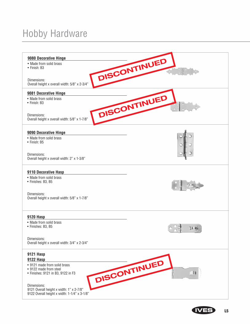
L5
9080 Decorative Hinge• Made from solid brass• Finish: B3
Dimensions:Overall height x overall width: 5/8” x 2-3/4”
9081 Decorative Hinge• Made from solid brass• Finish: B3
Dimensions:Overall height x overall width: 5/8” x 1-7/8”
9090 Decorative Hinge• Made from solid brass• Finish: B5
Dimensions:Overall height x overall width: 2” x 1-3/8”
9110 Decorative Hasp• Made from solid brass• Finishes: B3, B5
Dimensions:Overall height x overall width: 5/8” x 1-7/8”
9120 Hasp• Made from solid brass• Finishes: B3, B5
Dimensions:Overall height x overall width: 3/4” x 2-3/4”
Hobby Hardware
9121 Hasp9122 Hasp• 9121 made from solid brass• 9122 made from steel• Finishes: 9121 in B3, 9122 in F3
Dimensions:9121 Overall height x width: 1” x 2-7/8”9122 Overall height x width: 1-1/4” x 3-1/8”
DISCONTINUED
DISCONTINUED
DISCONTINUED
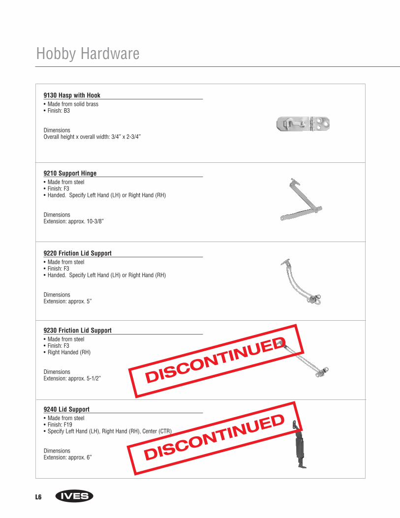
L6
Hobby Hardware
9130 Hasp with Hook• Made from solid brass• Finish: B3
DimensionsOverall height x overall width: 3/4” x 2-3/4”
9210 Support Hinge• Made from steel• Finish: F3• Handed. Specify Left Hand (LH) or Right Hand (RH)
DimensionsExtension: approx. 10-3/8”
9220 Friction Lid Support• Made from steel• Finish: F3• Handed. Specify Left Hand (LH) or Right Hand (RH)
DimensionsExtension: approx. 5”
9230 Friction Lid Support• Made from steel• Finish: F3• Right Handed (RH)
DimensionsExtension: approx. 5-1/2”
9240 Lid Support• Made from steel• Finish: F19• Specify Left Hand (LH), Right Hand (RH), Center (CTR)
DimensionsExtension: approx. 6”
DISCONTINUED
DISCONTINUED
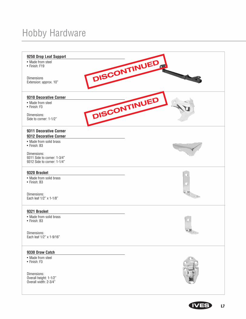
L7
Hobby Hardware
9250 Drop Leaf Support• Made from steel• Finish: F19
DimensionsExtension: approx. 10”
9310 Decorative Corner• Made from steel• Finish: F3
Dimensions:Side to corner: 1-1/2”
9311 Decorative Corner9312 Decorative Corner• Made from solid brass• Finish: B3
Dimensions:9311 Side to corner: 1-3/4”9312 Side to corner: 1-1/4”
9320 Bracket• Made from solid brass• Finish: B3
Dimensions:Each leaf 1/2” x 1-1/8”
9321 Bracket• Made from solid brass• Finish: B3
Dimensions:Each leaf 1/2” x 1-9/16”
9330 Draw Catch• Made from steel• Finish: F3
Dimensions: Overall height: 1-1/2”Overall width: 2-3/4”
DISCONTINUED
DISCONTINUED
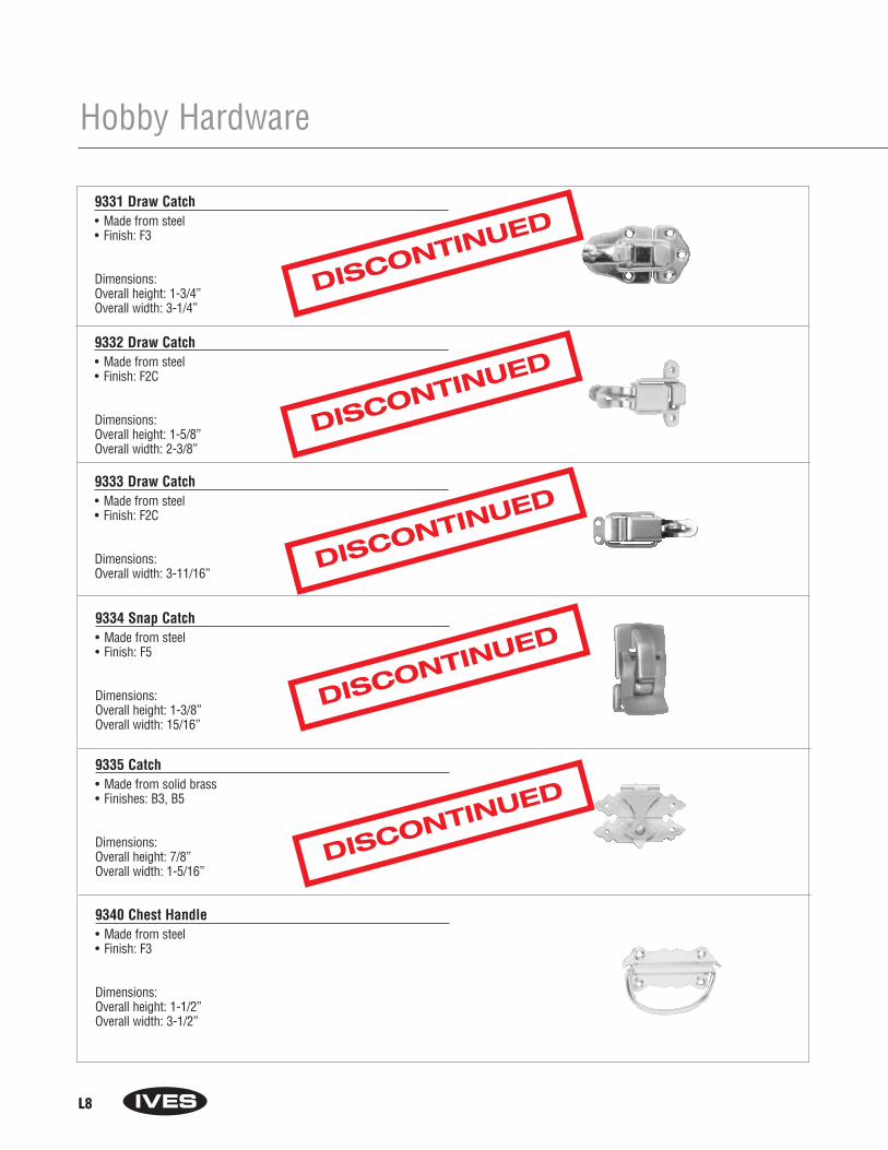
L8
Hobby Hardware
9331 Draw Catch• Made from steel• Finish: F3
Dimensions: Overall height: 1-3/4”Overall width: 3-1/4”
9332 Draw Catch• Made from steel• Finish: F2C
Dimensions: Overall height: 1-5/8”Overall width: 2-3/8”
9333 Draw Catch• Made from steel• Finish: F2C
Dimensions: Overall width: 3-11/16”
9334 Snap Catch• Made from steel• Finish: F5
Dimensions: Overall height: 1-3/8”Overall width: 15/16”
9335 Catch• Made from solid brass• Finishes: B3, B5
Dimensions: Overall height: 7/8”Overall width: 1-5/16”
9340 Chest Handle• Made from steel• Finish: F3
Dimensions:Overall height: 1-1/2”Overall width: 3-1/2”
DISCONTINUED
DISCONTINUED
DISCONTINUED
DISCONTINUED
DISCONTINUED

IVES Customer Service:1-877-613-87661-877-424-8494 FAX
©2003 Ingersoll-Rand Form IV-2001C Rev. 4/03 Printed in USA
DIVISION
8