Embed Size (px)
Citation preview
1Approved for public release, distribution unlimited
Workshop on X Ray Mission Architectural Concepts
December 14-15, 2011
Approved for public release, distribution unlimited
ADR Options for Future X-Ray Missions
Peter Shirron
NASA/GSFC
2Approved for public release, distribution unlimited
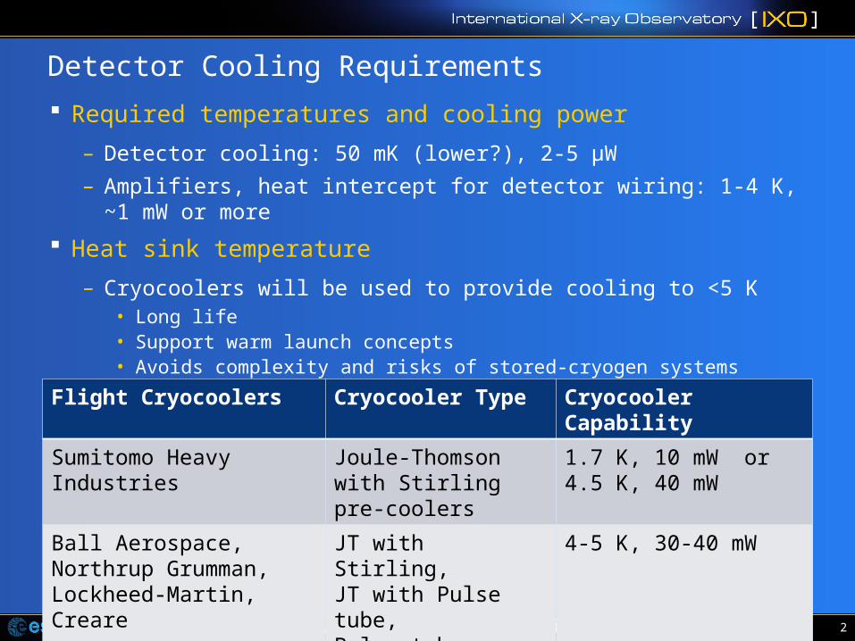
Detector Cooling Requirements
Required temperatures and cooling power
– Detector cooling: 50 mK (lower?), 2-5 µW
– Amplifiers, heat intercept for detector wiring: 1-4 K, ~1 mW or more
Heat sink temperature
– Cryocoolers will be used to provide cooling to <5 K• Long life• Support warm launch concepts• Avoids complexity and risks of stored-cryogen systems
Flight Cryocoolers Cryocooler Type Cryocooler Capability
Sumitomo Heavy Industries Joule-Thomson with Stirling pre-coolers
1.7 K, 10 mW or4.5 K, 40 mW
Ball Aerospace, Northrup Grumman, Lockheed-Martin, Creare
JT with Stirling, JT with Pulse tube, Pulse tube, Turbo-Brayton
4-5 K, 30-40 mW

3Approved for public release, distribution unlimited
Cooler Options
Low Temperature cooler options (flight) Demonstrated capability
– 3He sorption cooler >200 mK
– Dilution refrigeration (open cycle) 100 mK
– Adiabatic demagnetization refrigeration <20 mK
Can consider hybrid combinations
But…
– ADRs are considerably more efficient than other options, and can span the range from <20 mK to >5 K
– ADRs are more efficient than cryocoolers over the same temperature range
• From system perspective, it is advantageous to use ADRs over widest possible temperature range
4Approved for public release, distribution unlimited
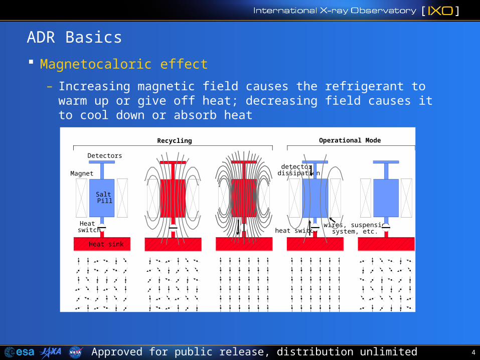
Operational Mode
Magnet
Detectors
Heat sink
SaltPill
Heatswitch
Recycling
detectordissipation
heat switchwires, suspension
system, etc.
ADR Basics
Magnetocaloric effect
– Increasing magnetic field causes the refrigerant to warm up or give off heat; decreasing field causes it to cool down or absorb heat
5Approved for public release, distribution unlimited
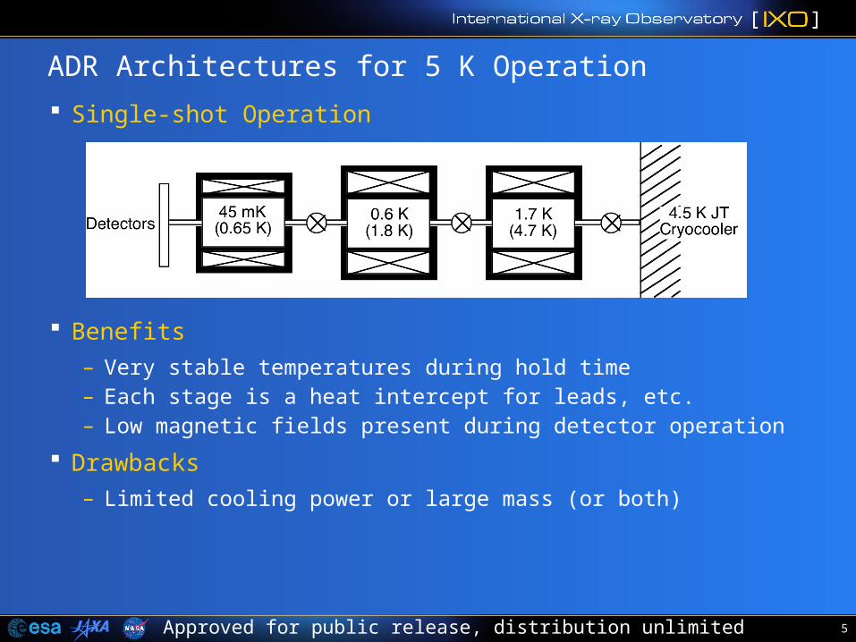
ADR Architectures for 5 K Operation
Single-shot Operation
Benefits
– Very stable temperatures during hold time– Each stage is a heat intercept for leads, etc.– Low magnetic fields present during detector operation
Drawbacks
– Limited cooling power or large mass (or both)
6Approved for public release, distribution unlimited
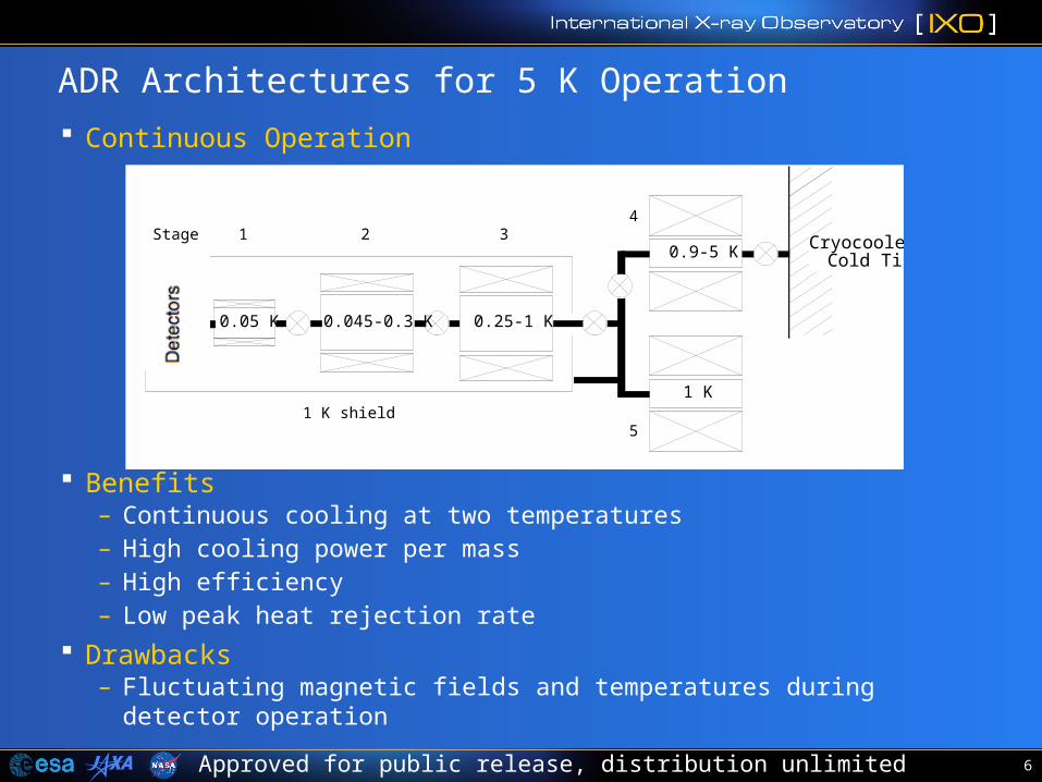
ADR Architectures for 5 K Operation
Continuous Operation
Benefits– Continuous cooling at two temperatures– High cooling power per mass– High efficiency– Low peak heat rejection rate
Drawbacks– Fluctuating magnetic fields and temperatures during detector operation
0.05 K 0.045-0.3 K
Cryocooler Cold Tip
0.25-1 K
0.9-5 KStage 1 2 3
4
1 K shield1 K
5
7Approved for public release, distribution unlimited
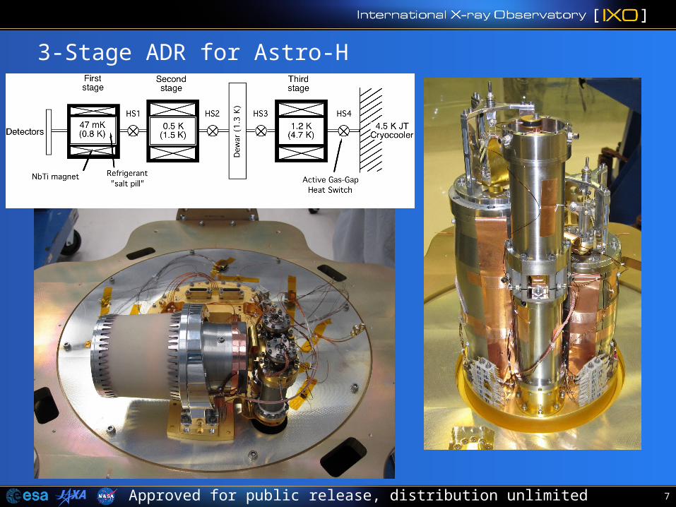
3-Stage ADR for Astro-H
8Approved for public release, distribution unlimited
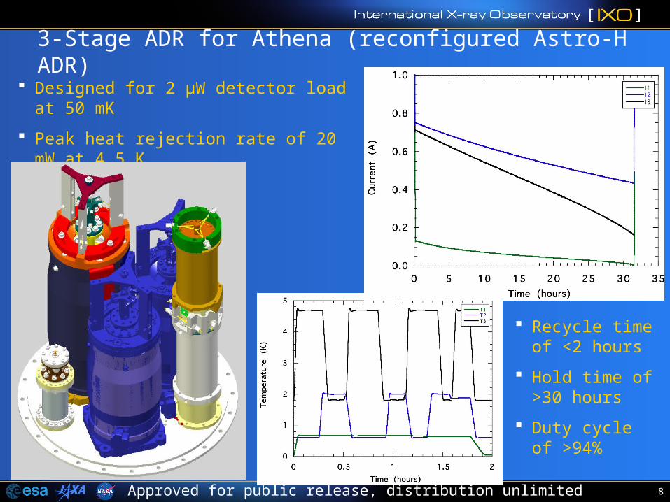
3-Stage ADR for Athena (reconfigured Astro-H ADR)
Designed for 2 µW detector load at 50 mK
Peak heat rejection rate of 20 mW at 4.5 K
15 kg total mass
Recycle time of <2 hours
Hold time of >30 hours
Duty cycle of >94%
9Approved for public release, distribution unlimited
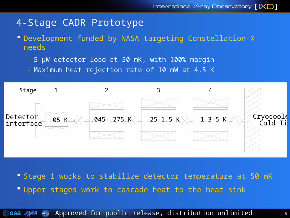
4-Stage CADR Prototype
Development funded by NASA targeting Constellation-X needs
– 5 µW detector load at 50 mK, with 100% margin
– Maximum heat rejection rate of 10 mW at 4.5 K
Stage 1 works to stabilize detector temperature at 50 mK
Upper stages work to cascade heat to the heat sink
Detectorinterface
.05 K .045-.275 K Cryocooler Cold Tip
.25-1.5 K 1.3-5 K
Stage 1 2 3 4
10Approved for public release, distribution unlimited
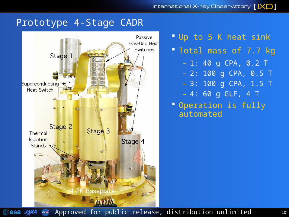
Prototype 4-Stage CADR Up to 5 K heat sink
Total mass of 7.7 kg
– 1: 40 g CPA, 0.2 T– 2: 100 g CPA, 0.5 T– 3: 100 g CPA, 1.5 T– 4: 60 g GLF, 4 T
Operation is fully automated
11Approved for public release, distribution unlimited
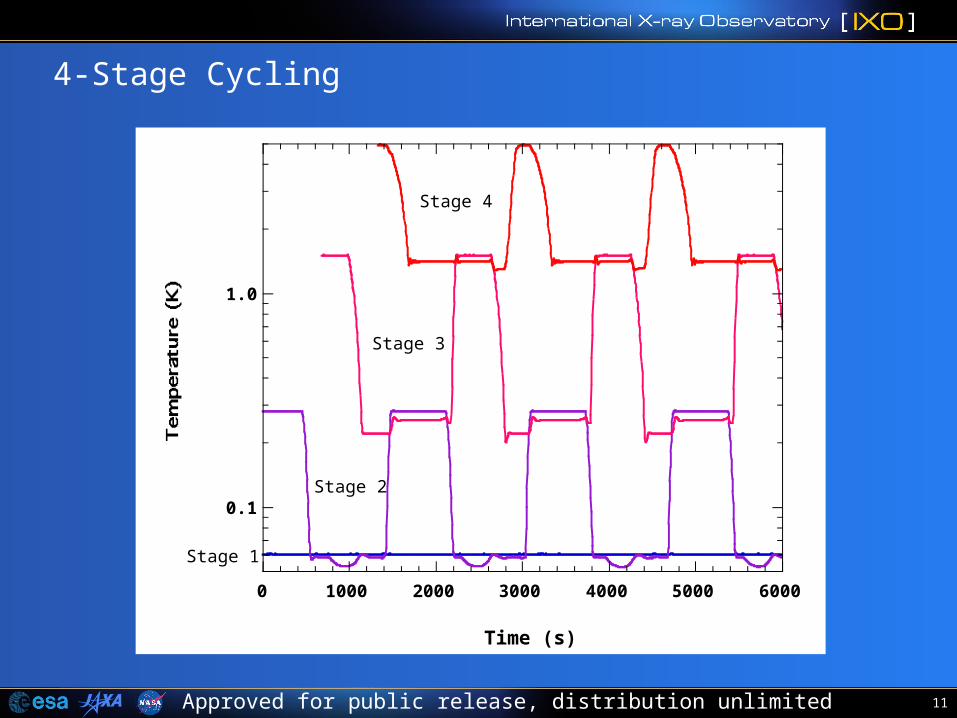
4-Stage Cycling
0.1
1.0
0 1000 2000 3000 4000 5000 6000
Time (s)
Stage 1
Stage 2
Stage 3
Stage 4
12Approved for public release, distribution unlimited
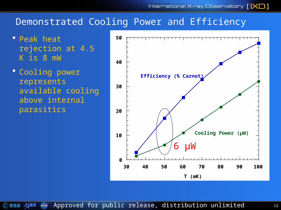
Demonstrated Cooling Power and Efficiency
Peak heat rejection at 4.5 K is 8 mW
Cooling power represents available cooling above internal parasitics
0
10
20
30
40
50
30 40 50 60 70 80 90 100
T (mK)
Efficiency (% Carnot)
Cooling Power (µW)
6 µW
13Approved for public release, distribution unlimited
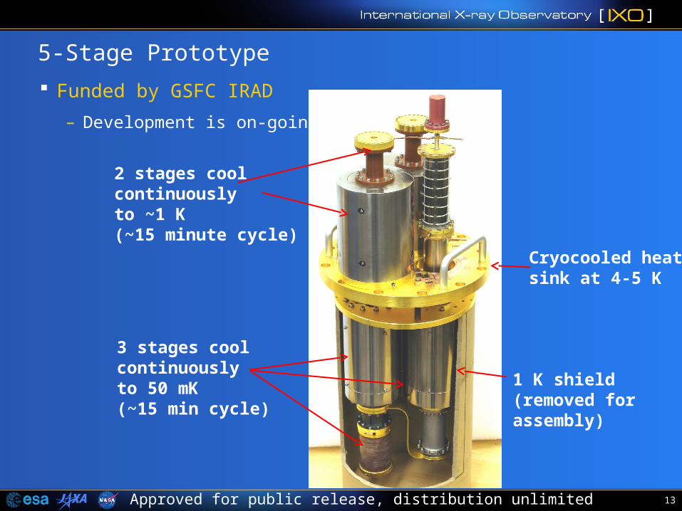
5-Stage Prototype
Funded by GSFC IRAD
– Development is on-going
2 stages coolcontinuouslyto ~1 K(~15 minute cycle)
3 stages coolcontinuouslyto 50 mK(~15 min cycle)
Cryocooled heatsink at 4-5 K
1 K shield(removed forassembly)
14Approved for public release, distribution unlimited
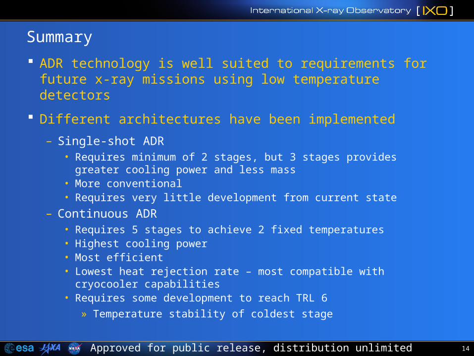
Summary
ADR technology is well suited to requirements for future x-ray missions using low temperature detectors
Different architectures have been implemented
– Single-shot ADR• Requires minimum of 2 stages, but 3 stages provides greater cooling power
and less mass• More conventional• Requires very little development from current state
– Continuous ADR• Requires 5 stages to achieve 2 fixed temperatures• Highest cooling power• Most efficient• Lowest heat rejection rate – most compatible with cryocooler capabilities• Requires some development to reach TRL 6
» Temperature stability of coldest stage


![(UNTITLED) [] · TH 103 MH 103 Approved For Release 2009/12/15 :CIA-RDP69B00041 8002100090005-2 Approved For Release 2009/12/15 :CIA-RDP69B00041 8002100090005-2 Approved For Release](https://img.pdfslide.net/doc/110x75/5e68568477414415fe43dd39/untitled-th-103-mh-103-approved-for-release-20091215-cia-rdp69b00041-8002100090005-2.jpg)