Embed Size (px)
Citation preview
1 Automotive Thermal Management IX How To
1 Automotive Thermal Management
1.1 Quick Information
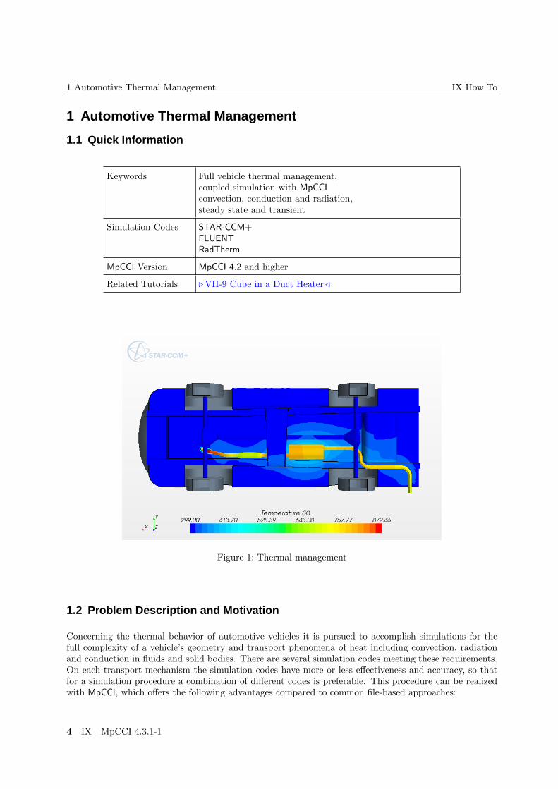
Keywords Full vehicle thermal management,coupled simulation with MpCCIconvection, conduction and radiation,steady state and transient
Simulation Codes STAR-CCM+FLUENTRadTherm
MpCCI Version MpCCI 4.2 and higher
Related Tutorials . VII-9 Cube in a Duct Heater /
Figure 1: Thermal management
1.2 Problem Description and Motivation
Concerning the thermal behavior of automotive vehicles it is pursued to accomplish simulations for thefull complexity of a vehicle’s geometry and transport phenomena of heat including convection, radiationand conduction in fluids and solid bodies. There are several simulation codes meeting these requirements.On each transport mechanism the simulation codes have more or less effectiveness and accuracy, so thatfor a simulation procedure a combination of different codes is preferable. This procedure can be realizedwith MpCCI, which offers the following advantages compared to common file-based approaches:
4 IX MpCCI 4.3.1-1
IX How To 1.3 Simulation Procedure
• Fully automatic and fast data transfer over socket connections.
• Easy implementation for repeating data transfer as used for iterative steady or transient simulations.
• Fast and robust data mapping between non-matching meshes.
• Data inter- and extrapolation on geometrical irregularities like partially non-matching geometries.
• Flexible steering of simulation procedure for instance with subcycling, time-step sharing and furtherfeatures depending on the applied simulation codes.
In this code of practice it is intended to demonstrate the procedure of coupling CFD codes STAR-CCM+or FLUENT with RadTherm for steady state and transient thermal simulations.
1.3 Simulation Procedure
1.3.1 Model Preparation
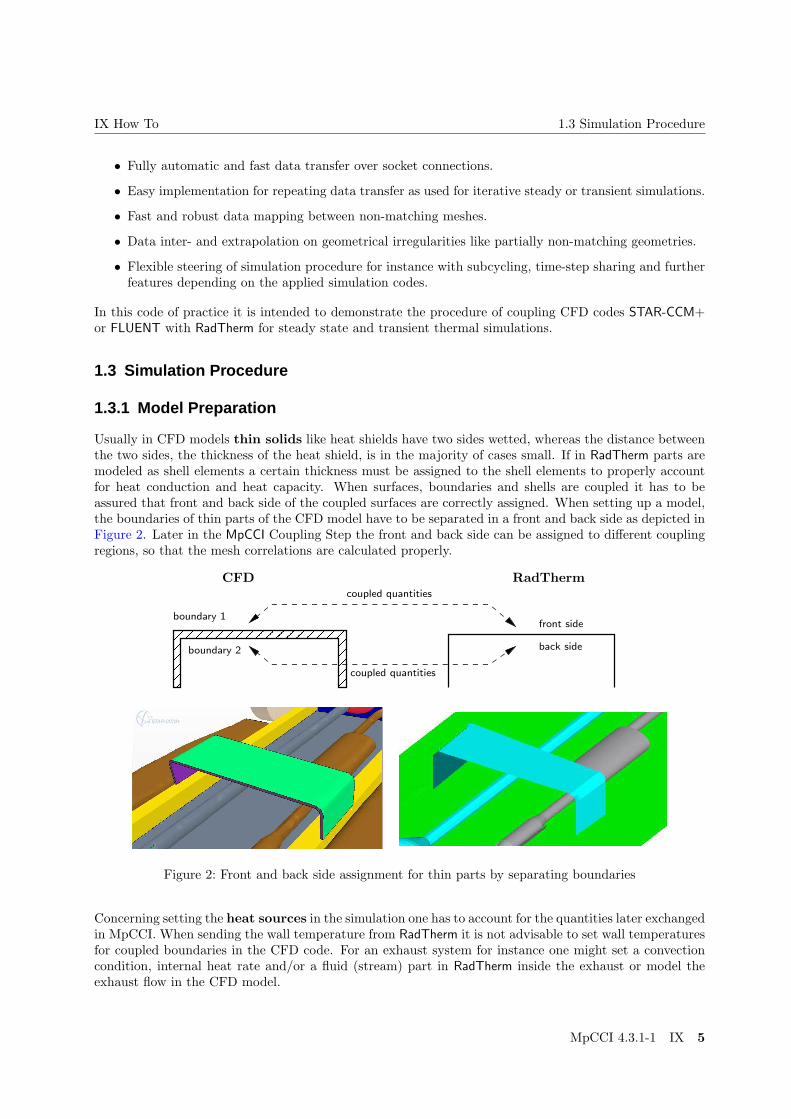
Usually in CFD models thin solids like heat shields have two sides wetted, whereas the distance betweenthe two sides, the thickness of the heat shield, is in the majority of cases small. If in RadTherm parts aremodeled as shell elements a certain thickness must be assigned to the shell elements to properly accountfor heat conduction and heat capacity. When surfaces, boundaries and shells are coupled it has to beassured that front and back side of the coupled surfaces are correctly assigned. When setting up a model,the boundaries of thin parts of the CFD model have to be separated in a front and back side as depicted inFigure 2. Later in the MpCCI Coupling Step the front and back side can be assigned to different couplingregions, so that the mesh correlations are calculated properly.
� � � � � � � � �� � � � � � � � �� � � � � � � � �� � � � � � � � �
� � � � � � � � �� � � � � � � � �� � � � � � � � �� � � � � � � � �
RadThermCFD
coupled quantities
coupled quantities
boundary 1
boundary 2 back side
front side
Figure 2: Front and back side assignment for thin parts by separating boundaries
Concerning setting the heat sources in the simulation one has to account for the quantities later exchangedin MpCCI. When sending the wall temperature from RadTherm it is not advisable to set wall temperaturesfor coupled boundaries in the CFD code. For an exhaust system for instance one might set a convectioncondition, internal heat rate and/or a fluid (stream) part in RadTherm inside the exhaust or model theexhaust flow in the CFD model.
MpCCI 4.3.1-1 IX 5

1 Automotive Thermal Management IX How To
1.3.2 MpCCI Setup
The model set-up in MpCCI corresponds to a typical thermal coupling procedure, where it is common andstable to exchange the heat coefficient and the film temperature to RadTherm and the wall temperatureto the CFD code. As already depicted in . 1.3.1 Model Preparation / it is necessary for thin parts toseparate the boundaries in CFD and define different coupling regions in MpCCI for front and back sides.A full vehicle features a lot of different boundaries which do not have to be coupled in separate couplingregions each. It is advisable to create groups of coupling regions which hold different part groups ofthe vehicle (Figure 3). It is also a good procedure to reflect the group name in the boundary name touse the MpCCI pattern matching (. V-4.4.4 Generate Regions /). In STAR-CCM+ it is quite common tocombine boundaries in certain groups and regions like engine, exhaust etc. . In this case the boundarynames available in MpCCI will already contain the group/region name used in STAR-CCM+.
Figure 3: Possible coupling meshes for a full vehicle reflecting part groups
It should be noted that not insulated back sides of shell element parts in RadTherm will appear inMpCCI with the string "-backside" added to the coupling part name . VI-17.2.3 Coupling Step /.
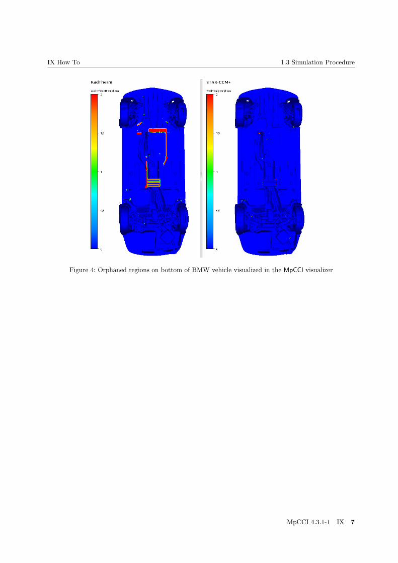
Although it is not desired in large full vehicle models, there are quite often geometrical discrepanciesbetween the coupled models, which usually leads to orphaned regions (Figure 4). There are three proce-dures for handling these orphaned regions. It is possible to modify the search parameter in order to catchgeometry deviations. Either the multiplicity factor for a dimensionless search or the normal dimensionfulsearch distance is raised. If the granularity of the coupling regions is coarse, e. g. all components in onecoupling region, it might result in wrong neighborhood associations especially when parts come in closecontact. The second procedure is to accept a default value for orphaned regions. As this might be rea-sonable for the heat coefficient which is usually set to zero (adiabatic), for wall temperatures it is kindof random and therefore restrictive. To overcome this problem MpCCI offers extrapolation to orphanedregions, where matched parts around the orphans define the inter- and extrapolated values. In Figure 5 theprocedures are compared for a hot spot in an underhood simulation. It is visible that in smaller orphanedregions the extrapolation is a pretty good approximation compared to the sender source distribution, butin large orphaned regions the extrapolated temperature distribution is getting more vague.
6 IX MpCCI 4.3.1-1
IX How To 1.3 Simulation Procedure
Figure 4: Orphaned regions on bottom of BMW vehicle visualized in the MpCCI visualizer
MpCCI 4.3.1-1 IX 7

1 Automotive Thermal Management IX How To
Orphaned regions on sender mesh
Wall temperature distribution on sender mesh
Wall temperature distribution on receiver mesh with default values for orphaned regions
Wall temperature distribution on receiver mesh with extrapolation for orphaned regions
Figure 5: Treatment of orphaned regions in MpCCI
8 IX MpCCI 4.3.1-1

IX How To 1.3 Simulation Procedure
1.3.3 Running the Simulation
The complete simulation process might be started from the MpCCI GUI, simply as batch job e. g. bympcci batch case.csp or via a batch queuing system like PBS, SGE, etc. If the simulation is startedfrom MpCCI GUI, for RadTherm, FLUENT and STAR-CCM+ it is possible to run the coupled simulationwith their own GUI. This procedure offers the possibility to display results during simulation besides theMpCCI Visualizer or interact with the simulation model.
RadTherm
RadTherm cannot be steered by a script/macro file. When the necessary MpCCI function hooks areplaced, RadTherm will exchange data with MpCCI through these functions. For a steady state simulation(duration=0s) after each iteration and for a transient simulation after each time step the exchange of datawill be accomplished.
STAR-CCM+
STAR-CCM+ must be steered by a STAR-CCM+ java macro file, which can be provided in MpCCI or in theSTAR-CCM+ GUI. The macro may contain all STAR-CCM+ java structures and additionally will containMpCCI functions like "mpcci.init()", "mpcci.exchange()" and "mpcci.exit()". Usually the macrowill contain a loop, where after or before each or several iterations or time-steps an exchange is committed.The information of the initial exchange defined in the MpCCI GUI will be handed over to the first call of"mpcci.exchange()".
FLUENT
In FLUENT the necessary routines (user-defined-functions) will be provided by MpCCI and it is possible tolet MpCCI hook the necessary functions automatically. In addition all MpCCI functions might be carriedout by the MpCCI Control Panel, which is available in the FLUENT GUI. When FLUENT is started in batchmode a journal file has to be supplied to run the simulation. The journal file might contain all FLUENTstructures, in case the user did not allow MpCCI to set the necessary hooks it should additionally containMpCCI function calls.
Smoothly interrupting a coupled simulation and then restarting the same simulation is a challenging task.If you run the job with the MpCCI GUI you can hit the Stop in order to provide a STOP/ABORT file ora signal to save the solution and quit the simulation codes gracefully. Unfortunately if one code is waitingfor data at this moment it might not be successful. When running on a batch system there is actually noway to smoothly stop the codes with a proper file save. In this case it is advisable to turn on periodicautosave of files in the simulation codes and then restart with the last saved states.
For further information of the procedures for each code see the Codes Manual part of the MpCCI manual.
MpCCI 4.3.1-1 IX 9

1 Automotive Thermal Management IX How To
1.3.4 Results
This application for full vehicle thermal simulation is presented by courtesy of BMW Germany.
STAR-CCM+ approx. 45 mio. cells: 15 regions, 525 boundariesMRF for fans and wheelsPorous regions for heat exchangers and cooling devicesWall rotation of shafts and axles
RadTherm approx 900.000 cells,323 shell parts13 fluid parts for exhaust system
MpCCI coupled quantities:STAR-CCM+ →RadTherm: film temperature, heat coefficientRadTherm →STAR-CCM+: wall temperature⇒ approx. 2 mio. faces coupled
Table 1: Model data
Figure 6: STAR-CCM+ full vehicle model of a BMW top and bottom view
10 IX MpCCI 4.3.1-1

IX How To 1.3 Simulation Procedure
Figure 7: RadTherm underbody model of a BMW top and bottom view
Figure 8: Wall temperature in STAR-CCM+ of BMW vehicle top and bottom view
MpCCI 4.3.1-1 IX 11

1 Automotive Thermal Management IX How To
Figure 9: Wall temperature in STAR-CCM+ of BMW vehicle front axle
12 IX MpCCI 4.3.1-1


![[Thesis]on MpCCI as a Coupling Library for FSI With CFX](https://img.pdfslide.net/doc/110x75/543d3c65b1af9f310a8b4623/thesison-mpcci-as-a-coupling-library-for-fsi-with-cfx.jpg)