Embed Size (px)
Citation preview
System identification and sensor fusion in dynamical systems!Thomas Schön, user.it.uu.se/~thosc112
Guest lecture - System identification!Uppsala, Sweden
1. Calibration of a camera and an IMU
Derive a good predictor!
Pose and solve an appropriate optimization problem (NLS)!
where,!
This is a standard gray-box system identification problem!!
We formulate it as a standard gray-box problem
System identification and sensor fusion in dynamical systems!Thomas Schön, user.it.uu.se/~thosc112
Guest lecture - System identification!Uppsala, Sweden
1. Calibration of a camera and an IMU
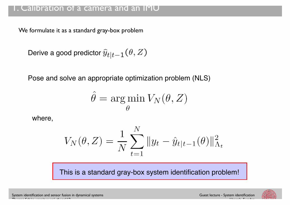
Rotate! Subtract gravity!
Inertial navigation:!
The gyroscopes measures the angular velocities!
The accelerometers measures the specific force!
System identification and sensor fusion in dynamical systems!Thomas Schön, user.it.uu.se/~thosc112
Guest lecture - System identification!Uppsala, Sweden
1. Calibration of a camera and an IMU
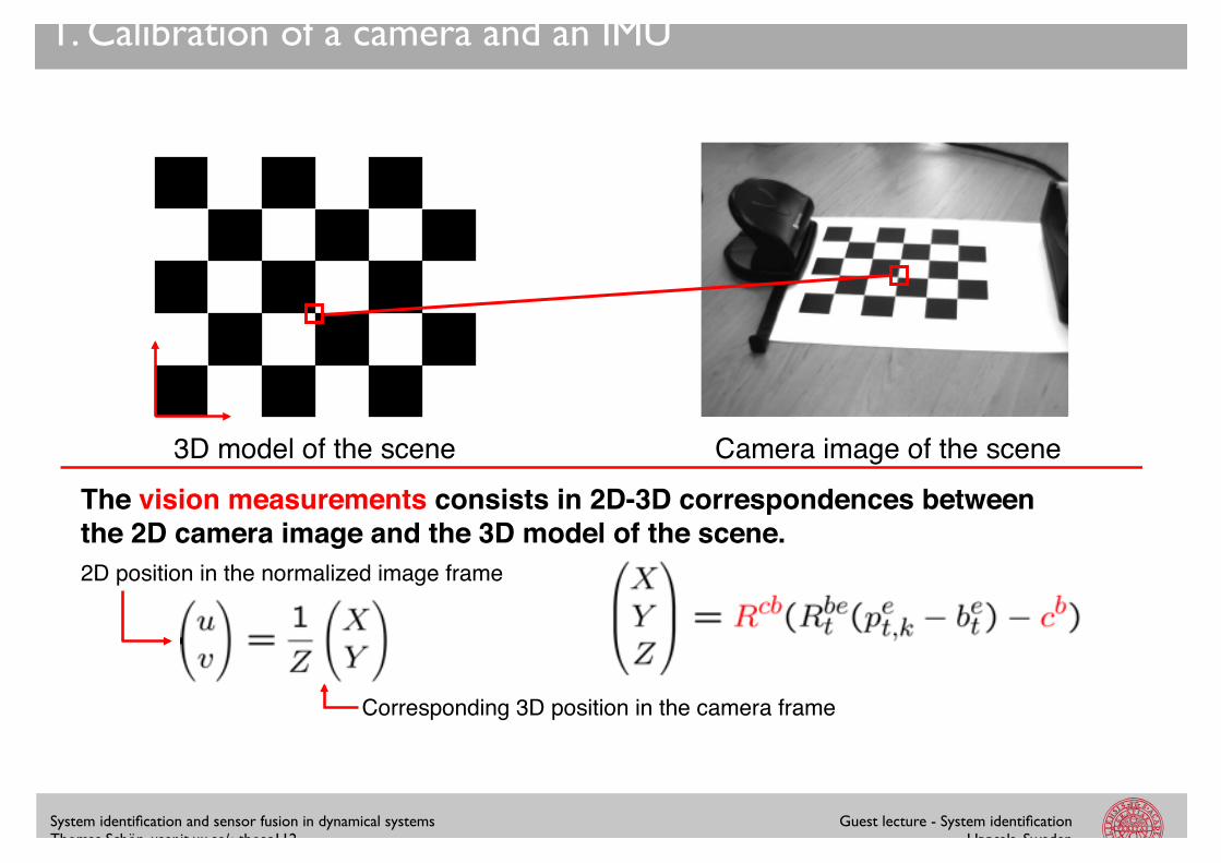
3D model of the scene! Camera image of the scene!
The vision measurements consists in 2D-3D correspondences between the 2D camera image and the 3D model of the scene.!
Corresponding 3D position in the camera frame !
2D position in the normalized image frame!
System identification and sensor fusion in dynamical systems!Thomas Schön, user.it.uu.se/~thosc112
Guest lecture - System identification!Uppsala, Sweden
1. Calibration of a camera and an IMU
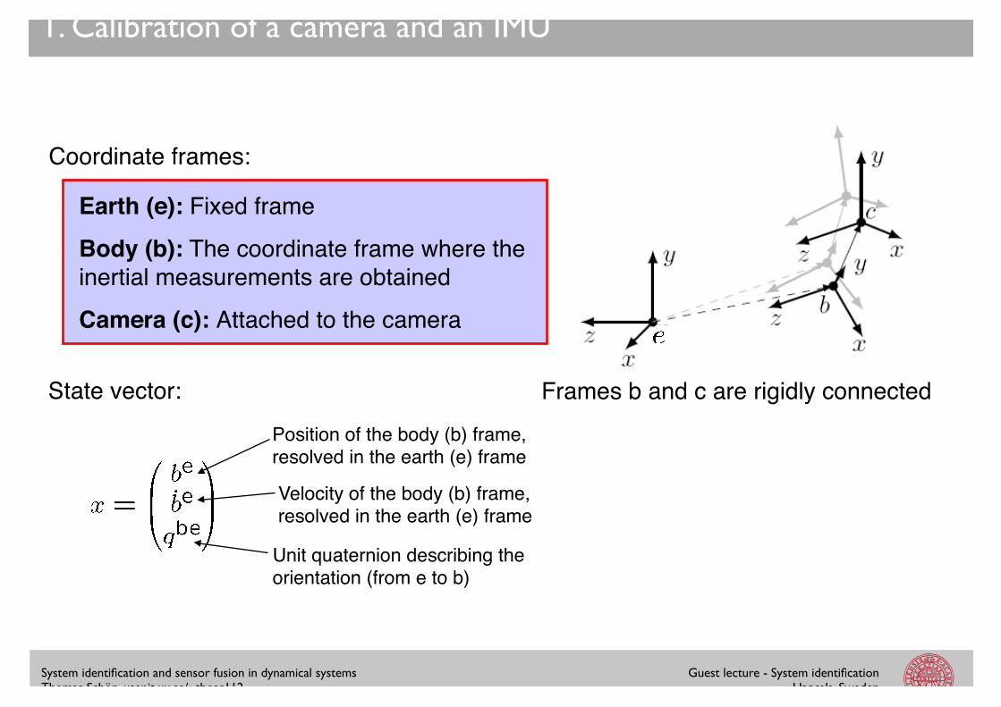
Coordinate frames:!
Earth (e): Fixed frame!
Body (b): The coordinate frame where the inertial measurements are obtained!
Camera (c): Attached to the camera!
State vector:!Position of the body (b) frame, resolved in the earth (e) frame!
Velocity of the body (b) frame, resolved in the earth (e) frame!
Unit quaternion describing the orientation (from e to b)!
Frames b and c are rigidly connected!
System identification and sensor fusion in dynamical systems!Thomas Schön, user.it.uu.se/~thosc112
Guest lecture - System identification!Uppsala, Sweden
1. Calibration of a camera and an IMU
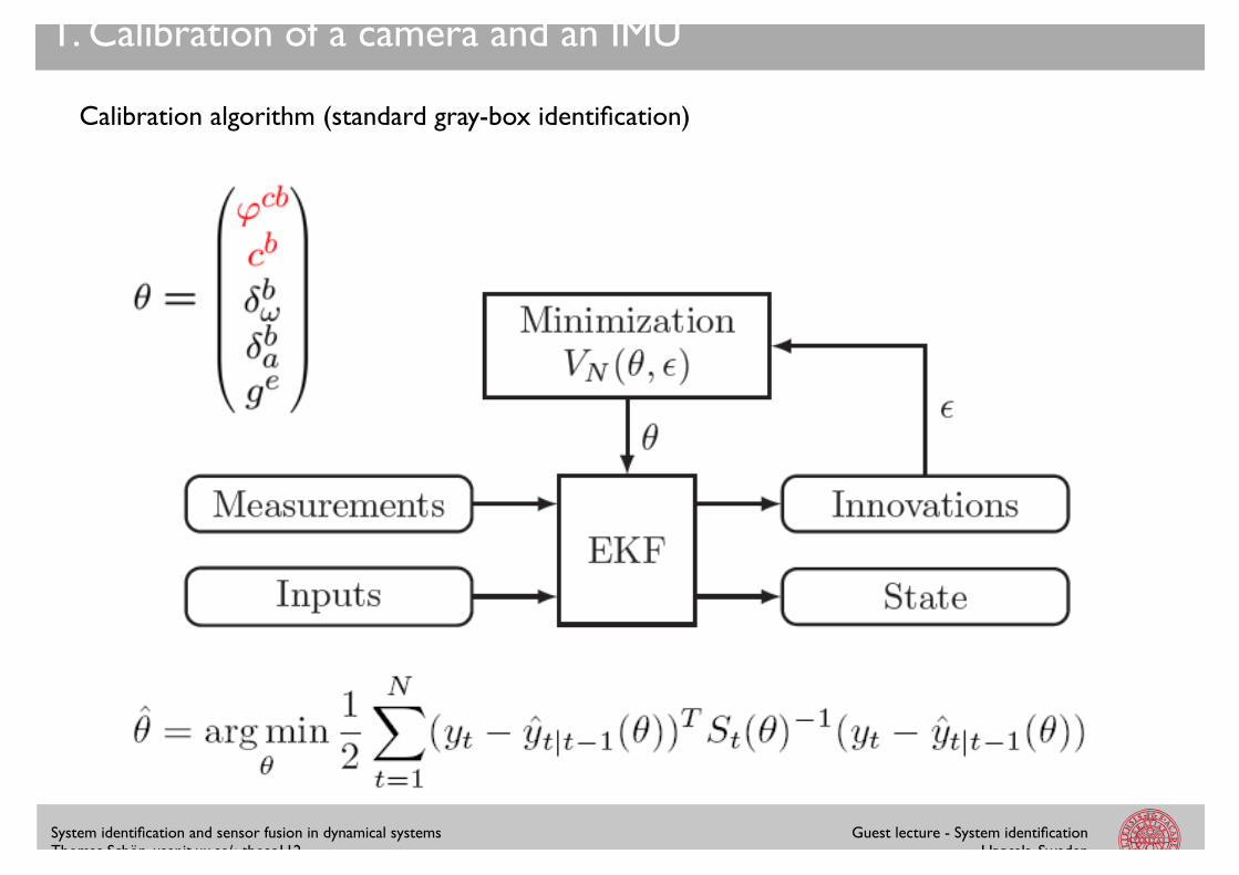
Calibration algorithm (standard gray-box identification)
System identification and sensor fusion in dynamical systems!Thomas Schön, user.it.uu.se/~thosc112
Guest lecture - System identification!Uppsala, Sweden
1. Calibration of a camera and an IMU
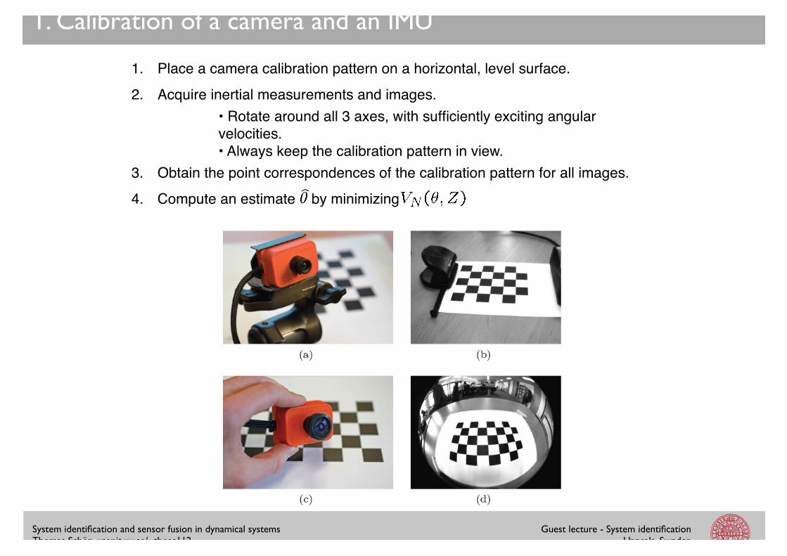
1. Place a camera calibration pattern on a horizontal, level surface."2. Acquire inertial measurements and images."
3. Obtain the point correspondences of the calibration pattern for all images."4. Compute an estimate by minimizing"
• Rotate around all 3 axes, with sufficiently exciting angular velocities."• Always keep the calibration pattern in view."
System identification and sensor fusion in dynamical systems!Thomas Schön, user.it.uu.se/~thosc112
Guest lecture - System identification!Uppsala, Sweden
1. Calibration of a camera and an IMU
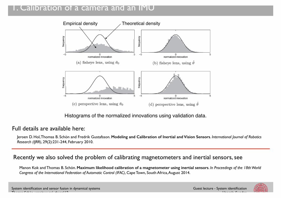
Histograms of the normalized innovations using validation data.!
Empirical density! Theoretical density!
Jeroen D. Hol, Thomas B. Schön and Fredrik Gustafsson. Modeling and Calibration of Inertial and Vision Sensors. International Journal of Robotics Research (IJRR), 29(2):231-244, February 2010.
Full details are available here:
Manon Kok and Thomas B. Schön. Maximum likelihood calibration of a magnetometer using inertial sensors. In Proceedings of the 18th World Congress of the International Federation of Automatic Control (IFAC), Cape Town, South Africa, August 2014.
Recently we also solved the problem of calibrating magnetometers and inertial sensors, see
System identification and sensor fusion in dynamical systems!Thomas Schön, user.it.uu.se/~thosc112
Guest lecture - System identification!Uppsala, Sweden
2. Autonomous helicopter landing (I/III)
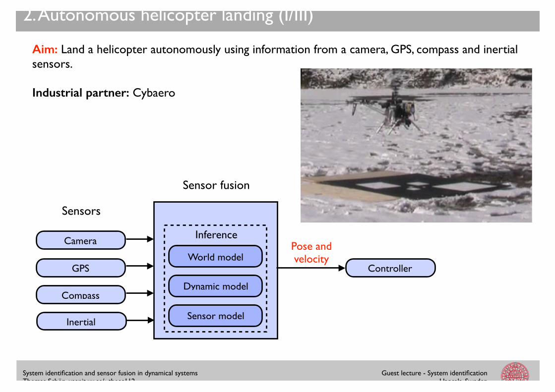
Aim: Land a helicopter autonomously using information from a camera, GPS, compass and inertial sensors.!!Industrial partner: Cybaero
World model
Inference
Dynamic model
Sensor model
Sensors
Sensor fusion
Pose and velocity
Camera
GPS
Compass
Inertial
Controller
System identification and sensor fusion in dynamical systems!Thomas Schön, user.it.uu.se/~thosc112
Guest lecture - System identification!Uppsala, Sweden
2. Autonomous helicopter landing (II/III)
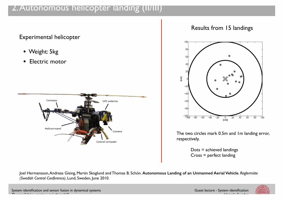
The two circles mark 0.5m and 1m landing error, respectively. !!
Dots = achieved landings!Cross = perfect landing
Results from 15 landings
Experimental helicopter!!• Weight: 5kg!!• Electric motor
Joel Hermansson, Andreas Gising, Martin Skoglund and Thomas B. Schön. Autonomous Landing of an Unmanned Aerial Vehicle. Reglermöte (Swedish Control Conference), Lund, Sweden, June 2010.
System identification and sensor fusion in dynamical systems!Thomas Schön, user.it.uu.se/~thosc112
Guest lecture - System identification!Uppsala, Sweden
2. Autonomous helicopter landing (III/III)
System identification and sensor fusion in dynamical systems!Thomas Schön, user.it.uu.se/~thosc112
Guest lecture - System identification!Uppsala, Sweden
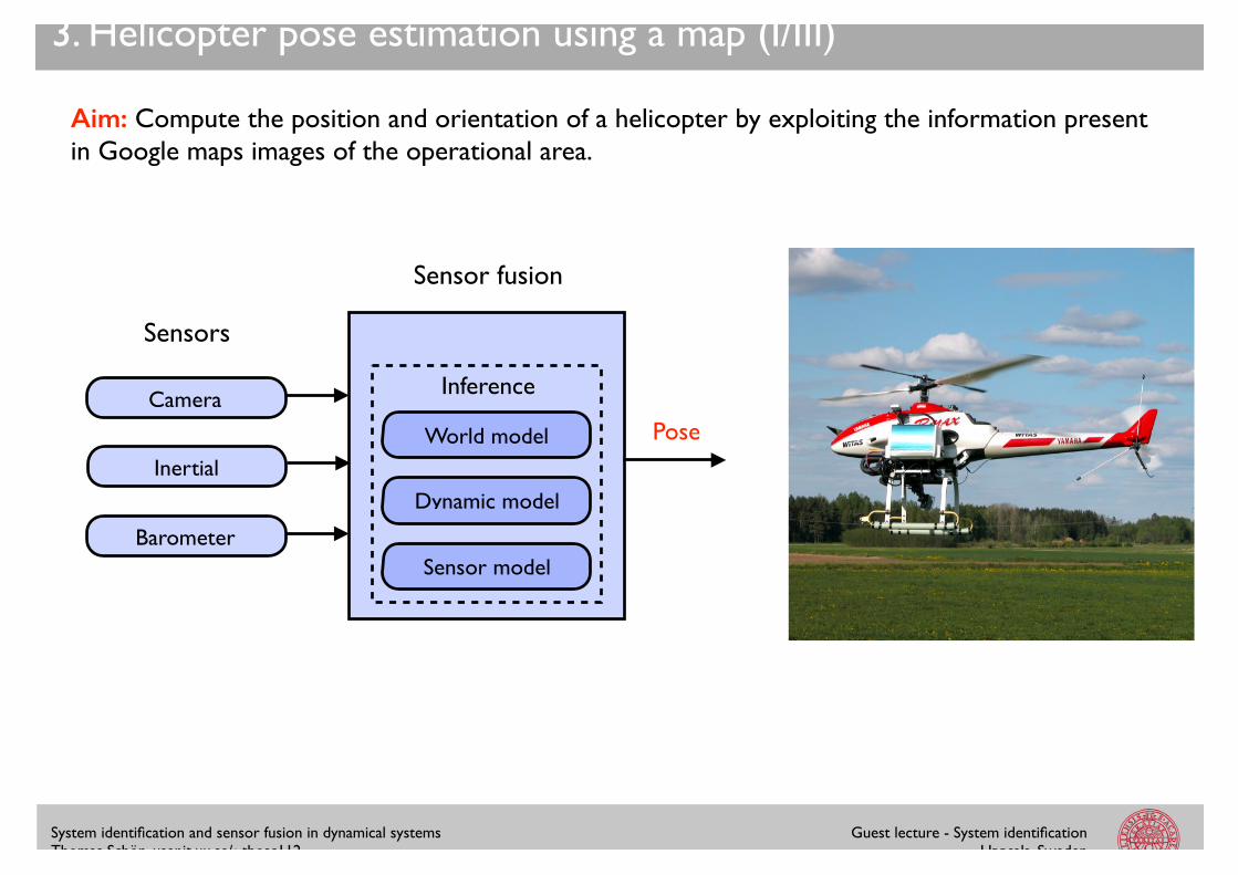
3. Helicopter pose estimation using a map (I/III)
Aim: Compute the position and orientation of a helicopter by exploiting the information present in Google maps images of the operational area.!
World model
Inference
Dynamic model
Sensor model
Sensors
Sensor fusion
PoseCamera
Inertial
Barometer
System identification and sensor fusion in dynamical systems!Thomas Schön, user.it.uu.se/~thosc112
Guest lecture - System identification!Uppsala, Sweden
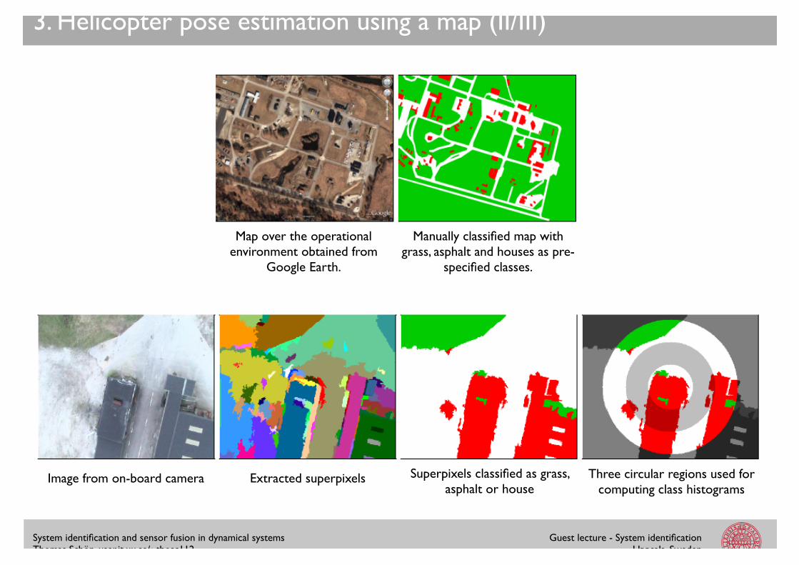
3. Helicopter pose estimation using a map (II/III)
Image from on-board camera Extracted superpixels Superpixels classified as grass, asphalt or house
Three circular regions used for computing class histograms
Map over the operational environment obtained from
Google Earth.
Manually classified map with grass, asphalt and houses as pre-
specified classes.
System identification and sensor fusion in dynamical systems!Thomas Schön, user.it.uu.se/~thosc112
Guest lecture - System identification!Uppsala, Sweden
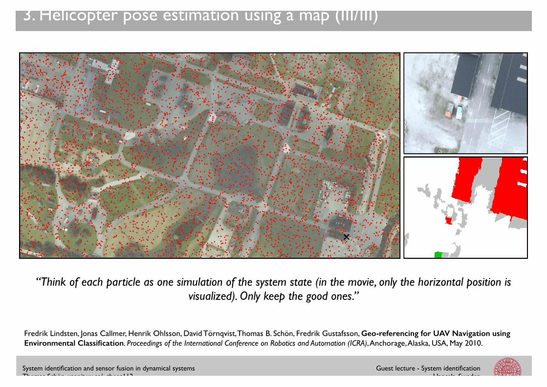
3. Helicopter pose estimation using a map (III/III)
“Think of each particle as one simulation of the system state (in the movie, only the horizontal position is visualized). Only keep the good ones.”
Fredrik Lindsten, Jonas Callmer, Henrik Ohlsson, David Törnqvist, Thomas B. Schön, Fredrik Gustafsson, Geo-referencing for UAV Navigation using Environmental Classification. Proceedings of the International Conference on Robotics and Automation (ICRA), Anchorage, Alaska, USA, May 2010.
System identification and sensor fusion in dynamical systems!Thomas Schön, user.it.uu.se/~thosc112
Guest lecture - System identification!Uppsala, Sweden
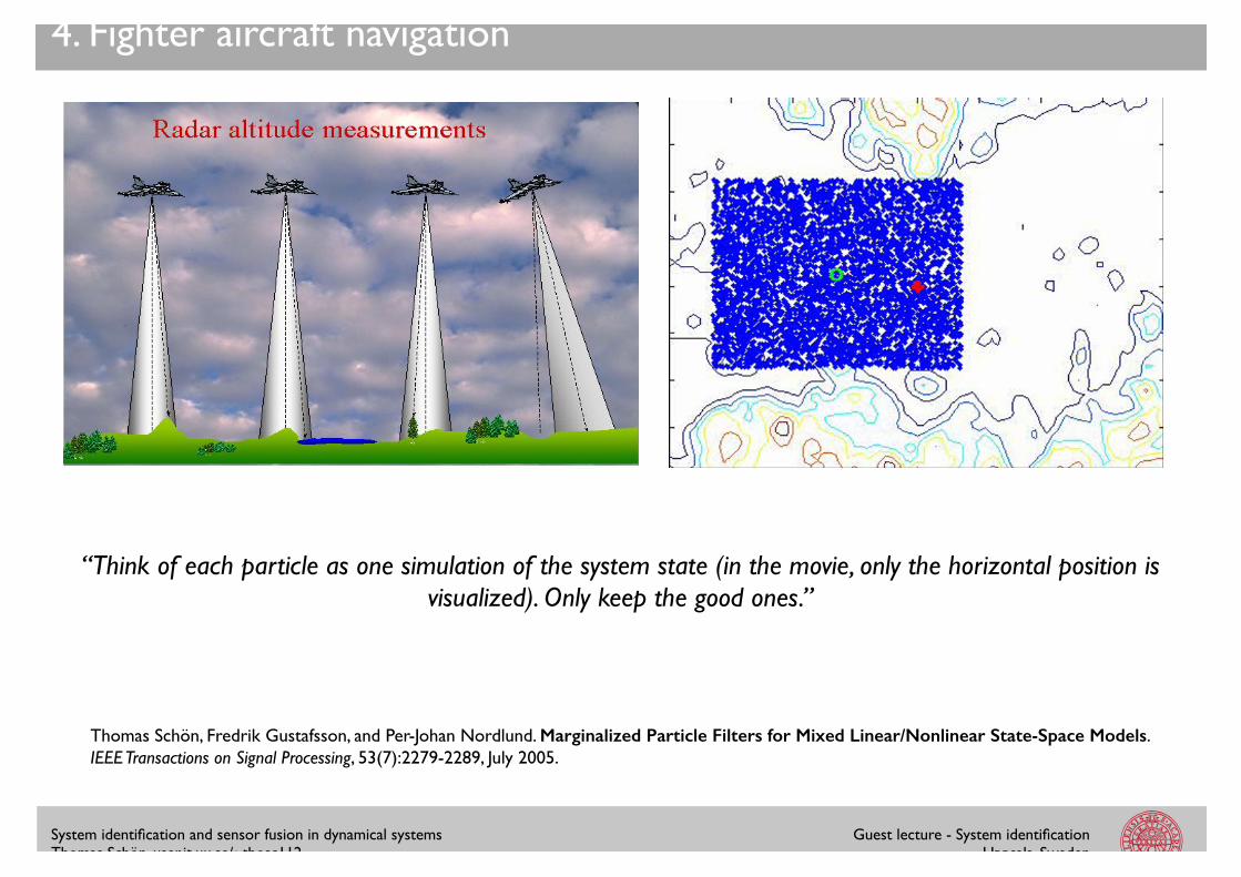
4. Fighter aircraft navigation
“Think of each particle as one simulation of the system state (in the movie, only the horizontal position is visualized). Only keep the good ones.”
Thomas Schön, Fredrik Gustafsson, and Per-Johan Nordlund. Marginalized Particle Filters for Mixed Linear/Nonlinear State-Space Models. IEEE Transactions on Signal Processing, 53(7):2279-2289, July 2005.
System identification and sensor fusion in dynamical systems!Thomas Schön, user.it.uu.se/~thosc112
Guest lecture - System identification!Uppsala, Sweden
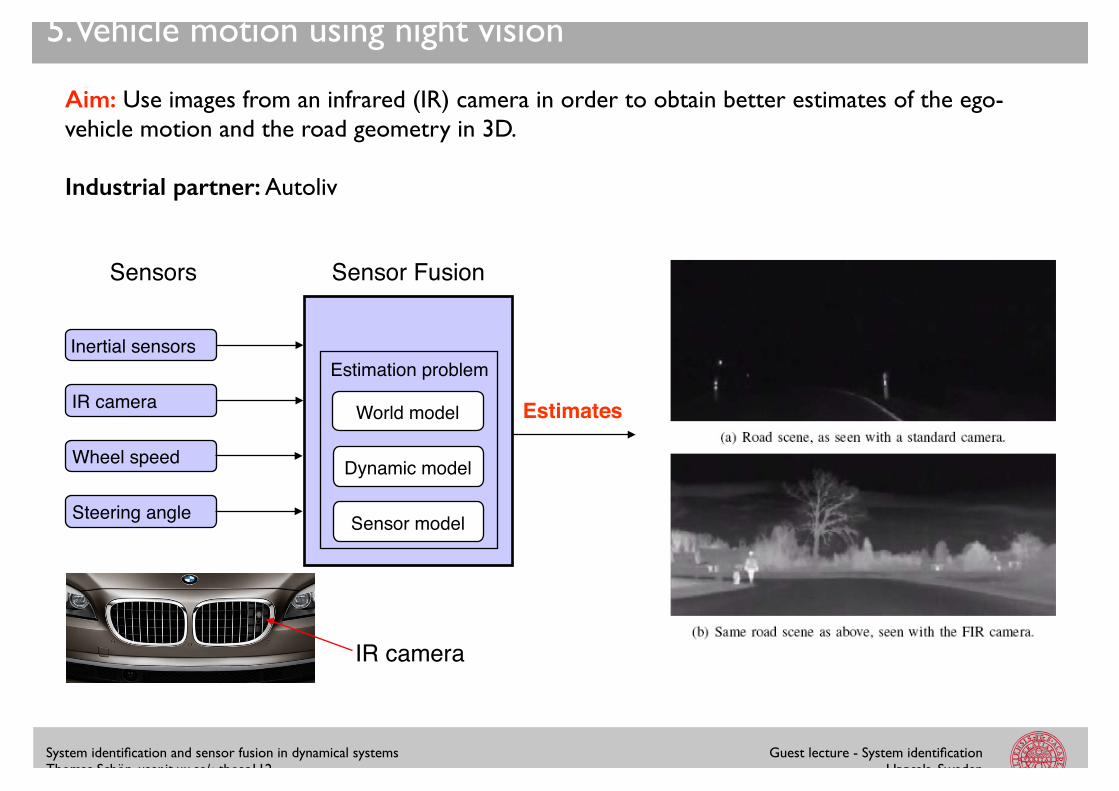
5. Vehicle motion using night vision
Aim: Use images from an infrared (IR) camera in order to obtain better estimates of the ego-vehicle motion and the road geometry in 3D.!!Industrial partner: Autoliv
Sensors! Sensor Fusion!
Estimates!
Inertial sensors!
IR camera!
Wheel speed!
Steering angle!
Dynamic model!
Sensor model!
Estimation problem!
World model!
IR camera!
System identification and sensor fusion in dynamical systems!Thomas Schön, user.it.uu.se/~thosc112
Guest lecture - System identification!Uppsala, Sweden
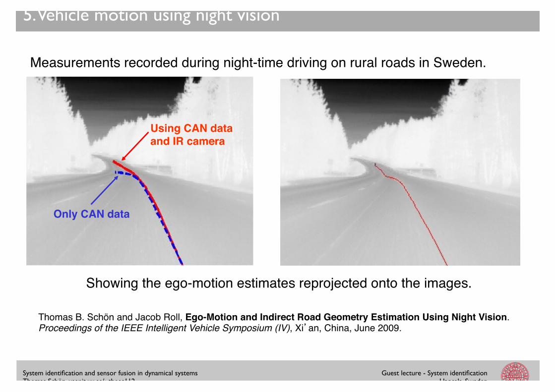
5. Vehicle motion using night vision
Measurements recorded during night-time driving on rural roads in Sweden.!
Using CAN data and IR camera!
Only CAN data!
Showing the ego-motion estimates reprojected onto the images.!
Thomas B. Schön and Jacob Roll, Ego-Motion and Indirect Road Geometry Estimation Using Night Vision. Proceedings of the IEEE Intelligent Vehicle Symposium (IV), Xi�an, China, June 2009. !
System identification and sensor fusion in dynamical systems!Thomas Schön, user.it.uu.se/~thosc112
Guest lecture - System identification!Uppsala, Sweden
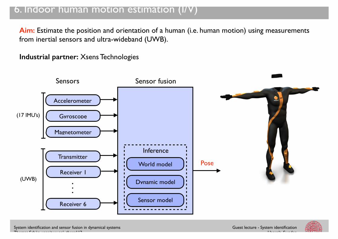
Aim: Estimate the position and orientation of a human (i.e. human motion) using measurements from inertial sensors and ultra-wideband (UWB).!!Industrial partner: Xsens Technologies
4. Indoor human motion estimation
6. Indoor human motion estimation (I/V)
World model
Inference
Dynamic model
Sensor model
Sensors Sensor fusion
Pose
Accelerometer
Gyroscope
Magnetometer
(17 IMU’s)
(UWB)
Transmitter
Receiver 1
Receiver 6
...
System identification and sensor fusion in dynamical systems!Thomas Schön, user.it.uu.se/~thosc112
Guest lecture - System identification!Uppsala, Sweden
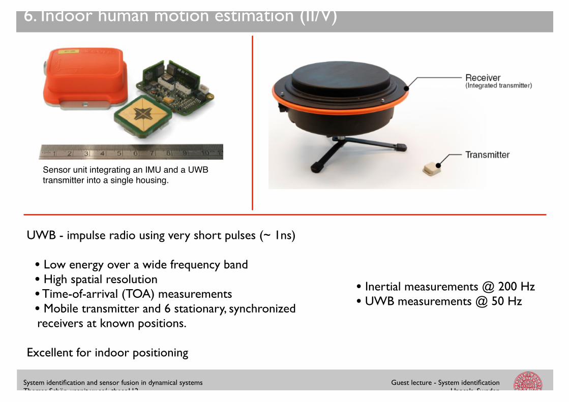
Sensor unit integrating an IMU and a UWB transmitter into a single housing.!
• Inertial measurements @ 200 Hz!• UWB measurements @ 50 Hz
6. Indoor human motion estimation (II/V)
UWB - impulse radio using very short pulses (~ 1ns)!!• Low energy over a wide frequency band!• High spatial resolution!• Time-of-arrival (TOA) measurements!• Mobile transmitter and 6 stationary, synchronized receivers at known positions.!!
Excellent for indoor positioning

System identification and sensor fusion in dynamical systems!Thomas Schön, user.it.uu.se/~thosc112
Guest lecture - System identification!Uppsala, Sweden
6. Indoor human motion estimation (III/V)
Performance evaluation using a camera-based reference system (Vicon).!!RMSE: 0.6 deg. in orientation and 5 cm in position.
Jeroen Hol, Thomas B. Schön and Fredrik Gustafsson, Ultra-Wideband Calibration for Indoor Positioning. Proceedings of the IEEE International Conference on Ultra-Wideband (ICUWB), Nanjing, China, September 2010.!!Jeroen Hol, Fred Dijkstra, Henk Luinge and Thomas B. Schön, Tightly Coupled UWB/IMU Pose Estimation. Proceedings of the IEEE International Conference on Ultra-Wideband (ICUWB), Vancouver, Canada, September 2009.
System identification and sensor fusion in dynamical systems!Thomas Schön, user.it.uu.se/~thosc112
Guest lecture - System identification!Uppsala, Sweden
6. Indoor human motion estimation (IV/V)
Show movie using VLC…
Manon Kok, Jeroen Hol and Thomas B. Schön. An optimization-based approach to human body motion capture using inertial sensors. In Proceedings of the 18th World Congress of the International Federation of Automatic Control (IFAC), Cape Town, South Africa, August 2014.
System identification and sensor fusion in dynamical systems!Thomas Schön, user.it.uu.se/~thosc112
Guest lecture - System identification!Uppsala, Sweden
6. Indoor human motion estimation (V/V)
Show movie using VLC…
System identification and sensor fusion in dynamical systems!Thomas Schön, user.it.uu.se/~thosc112
Guest lecture - System identification!Uppsala, Sweden
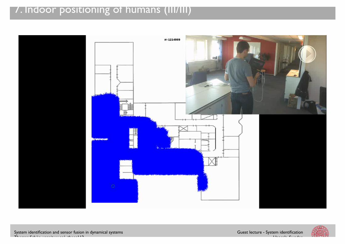
7. Indoor positioning of humans (I/III)
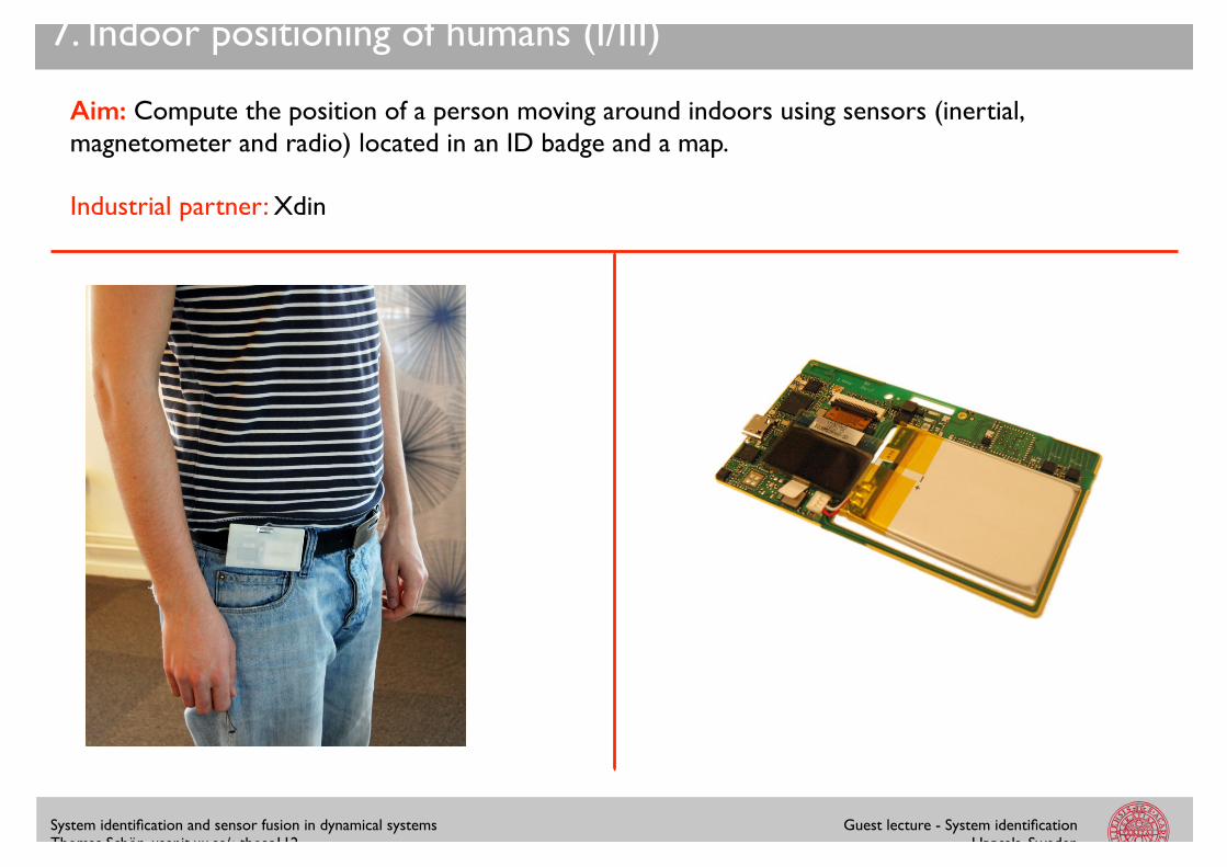
Aim: Compute the position of a person moving around indoors using sensors (inertial, magnetometer and radio) located in an ID badge and a map.!!Industrial partner: Xdin
1.5 Xdin 3
(a) A Beebadge, carrying a numberof sensors and a IEEE 802.15.4 radiochip.
(b) A coordinator, equipped bothwith a radio chip and an Ethernetport, serving as a base station for theBeebadges.
Figure 1.1. The two main components of the radio network.
Figure 1.2. Beebadge worn by a man.
System identification and sensor fusion in dynamical systems!Thomas Schön, user.it.uu.se/~thosc112
Guest lecture - System identification!Uppsala, Sweden
7. Indoor positioning of humans (II/III)
48 Approach
(a) An estimated trajectory at Xdin’s of-fice, 1000 particles represented as circles,size of a circle indicates the weight of theparticle.
(b) A scenario where the filter have notconverged yet. The spread in hypothesesis caused by a large coverage for a coordi-nator.
Figure 4.10. Output from the particle filter.
Figure 4.11. Illustration of a problematic case where a correct trajectory (green) isbeing starved by an incorrect trajectory (red), causing the filter to potentially diverge.
2.5 Map 15
(a) Relative probability density for parts ofXdin’s o�ce, the bright areas are rooms andthe bright lines are corridors that interconnectthe rooms
−1.5 −1 −0.5 0 0.5 1 1.50
0.2
0.4
0.6
0.8
1
Position [m]
Rela
tive p
robabili
ty
Decay for different n
n=2, m=1n=3, m=1n=4, m=1
(b) Cross section of the relative prob-ability function for a line with di�er-ent n
Figure 2.7. Probability interpretation of the map.
those would su�ce to give a magnitude of the force. The force is intuitivelydirected orthogonally from the wall towards the target and multiple forces canbe added together to get a resulting force a�ecting the momentum of the target.
Equation (2.9) describes how the force is constructed. The function wallj
(p)is a convex function giving the magnitude and direction of the force given theposition of the target, p.
fi
=ÿjœW
wallj
(pi
), where W is the set of walls. (2.9)
If positions from other targets are available, repellent forces from them can bemodeled as well, which is thoroughly discussed in [22]. The concept is visualizedin Figure 2.8 where the target T
i
is a�ected by two walls and another targetT
m
, resulting in the force fi
.
Figure 2.8. Force vectors illustrating the resulting force a�ecting a pedestrian.
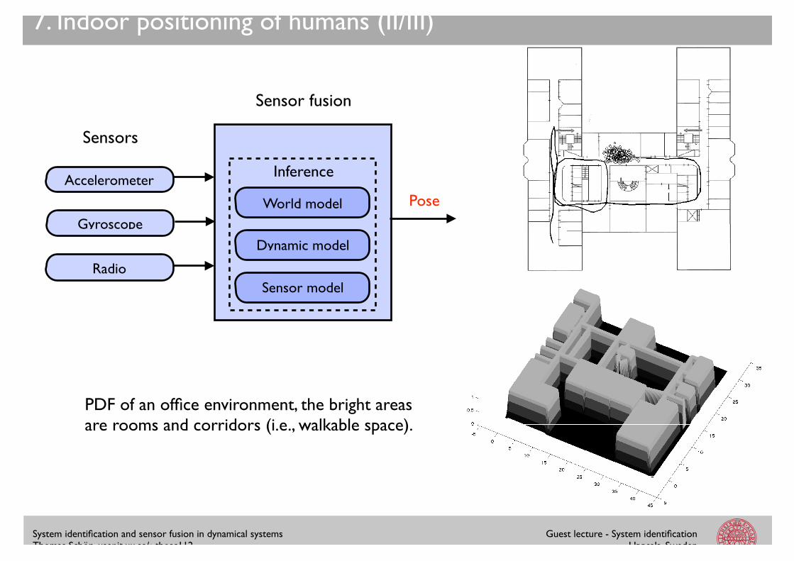
PDF of an office environment, the bright areas are rooms and corridors (i.e., walkable space).
World model
Inference
Dynamic model
Sensor model
Sensors
Sensor fusion
PoseAccelerometer
Gyroscope
Radio
System identification and sensor fusion in dynamical systems!Thomas Schön, user.it.uu.se/~thosc112
Guest lecture - System identification!Uppsala, Sweden
7. Indoor positioning of humans (III/III)
System identification and sensor fusion in dynamical systems!Thomas Schön, user.it.uu.se/~thosc112
Guest lecture - System identification!Uppsala, Sweden
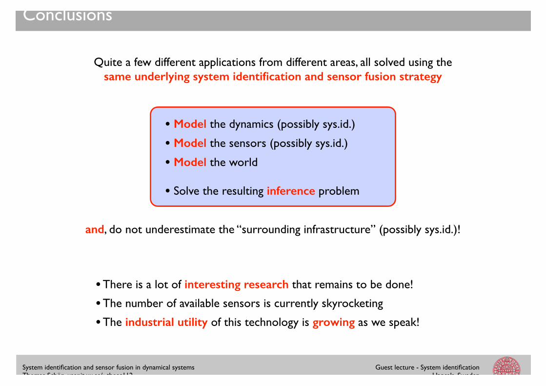
Conclusions
Quite a few different applications from different areas, all solved using the !same underlying system identification and sensor fusion strategy
• Model the dynamics (possibly sys.id.)!!• Model the sensors (possibly sys.id.)!!• Model the world!!
• Solve the resulting inference problem
and, do not underestimate the “surrounding infrastructure” (possibly sys.id.)!
• There is a lot of interesting research that remains to be done!!!• The number of available sensors is currently skyrocketing !!• The industrial utility of this technology is growing as we speak!

System identification and sensor fusion in dynamical systems!Thomas Schön, user.it.uu.se/~thosc112
Guest lecture - System identification!Uppsala, Sweden
2.5 Map 15
(a) Relative probability density for parts ofXdin’s o�ce, the bright areas are rooms andthe bright lines are corridors that interconnectthe rooms
−1.5 −1 −0.5 0 0.5 1 1.50
0.2
0.4
0.6
0.8
1
Position [m]
Rela
tive p
robabili
ty
Decay for different n
n=2, m=1n=3, m=1n=4, m=1
(b) Cross section of the relative prob-ability function for a line with di�er-ent n
Figure 2.7. Probability interpretation of the map.
those would su�ce to give a magnitude of the force. The force is intuitivelydirected orthogonally from the wall towards the target and multiple forces canbe added together to get a resulting force a�ecting the momentum of the target.
Equation (2.9) describes how the force is constructed. The function wallj
(p)is a convex function giving the magnitude and direction of the force given theposition of the target, p.
fi
=ÿjœW
wallj
(pi
), where W is the set of walls. (2.9)
If positions from other targets are available, repellent forces from them can bemodeled as well, which is thoroughly discussed in [22]. The concept is visualizedin Figure 2.8 where the target T
i
is a�ected by two walls and another targetT
m
, resulting in the force fi
.
Figure 2.8. Force vectors illustrating the resulting force a�ecting a pedestrian.
1.5 Xdin 3
(a) A Beebadge, carrying a numberof sensors and a IEEE 802.15.4 radiochip.
(b) A coordinator, equipped bothwith a radio chip and an Ethernetport, serving as a base station for theBeebadges.
Figure 1.1. The two main components of the radio network.
Figure 1.2. Beebadge worn by a man.
p(xt | y1:t) =h(yt | xt)p(xt | y1:t�1)
p(yt | y1:t�1),
p(xt | y1:t�1) =
Zf(xt | xt�1)p(xt�1 | y1:t�1)dxt�1,
xt+1 | xt ⇠ f✓(xt+1 | xt, ut),
yt | xt ⇠ h✓(yt | xt, ut).
Thank you for your attention!!