Embed Size (px)
Citation preview
1
Cams
• Cams are used to convert rotary motion to oscillatory motion (almost always) or oscillatory motion to rotary motion (rarely)
• For high speed applications – example, internal combustion engines
• Objectives of this chapter:– Learn fundamental concepts and terminology
– Learn how to design a cam and follower set to achieve a desired output motion.
2
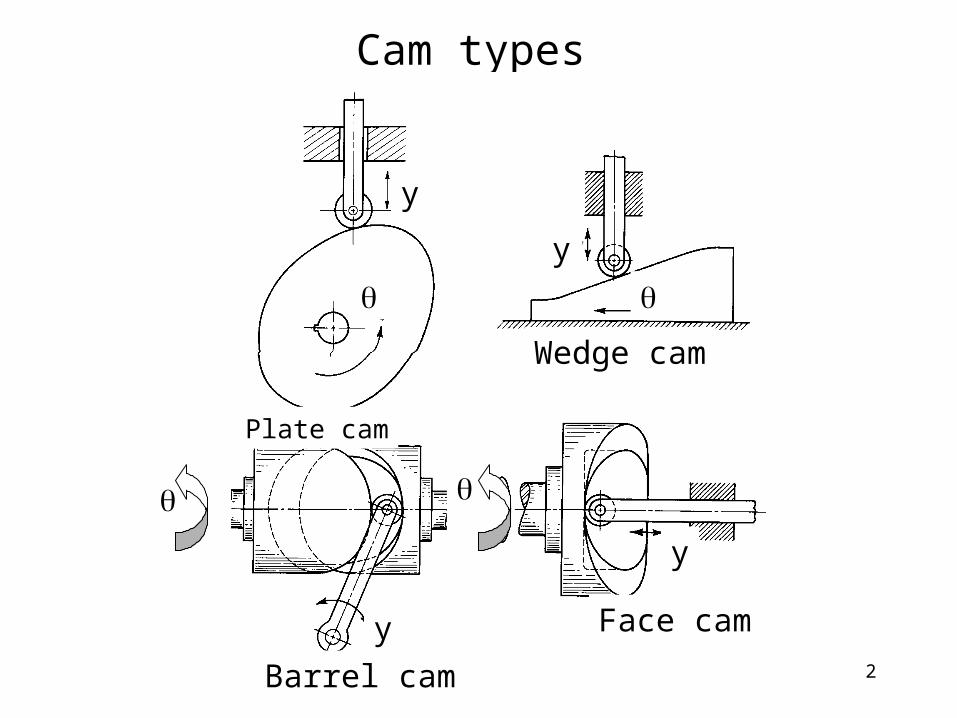
Cam types
Plate cam
Wedge cam
Barrel cam
Face cam
y
y
y
y
3
Followers
• Knife-edge
• Flat-face
• Roller
• Sperical-face
4
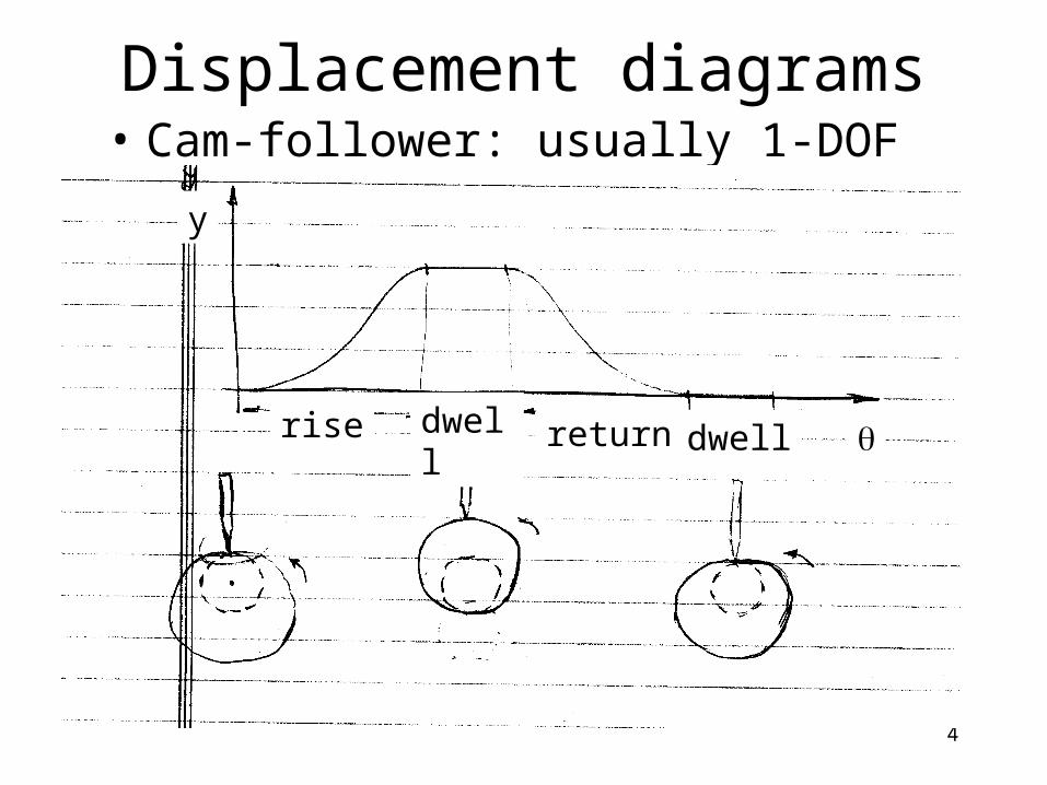
Displacement diagrams• Cam-follower: usually 1-DOF system
rise dwell return dwell
y
5
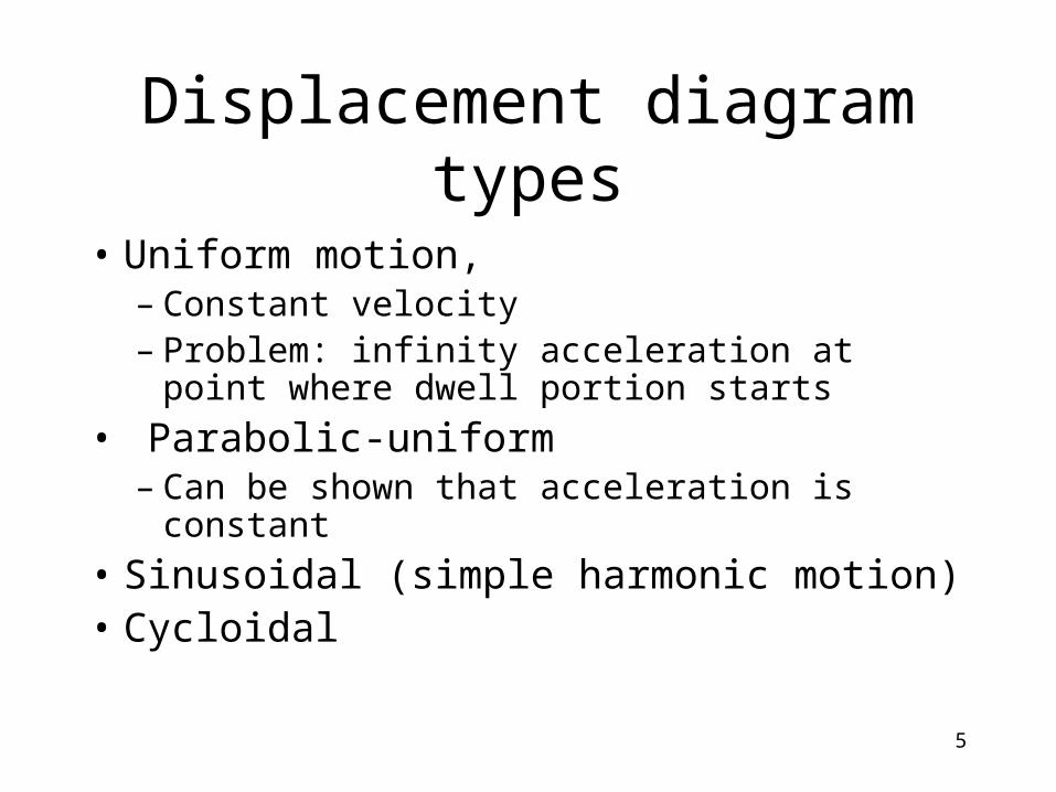
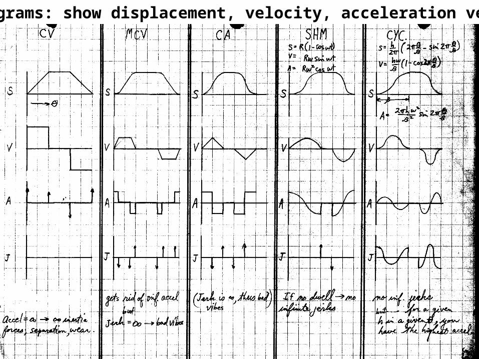
Displacement diagram types
• Uniform motion, – Constant velocity– Problem: infinity acceleration at point where
dwell portion starts
• Parabolic-uniform– Can be shown that acceleration is constant
• Sinusoidal (simple harmonic motion)• Cycloidal
6
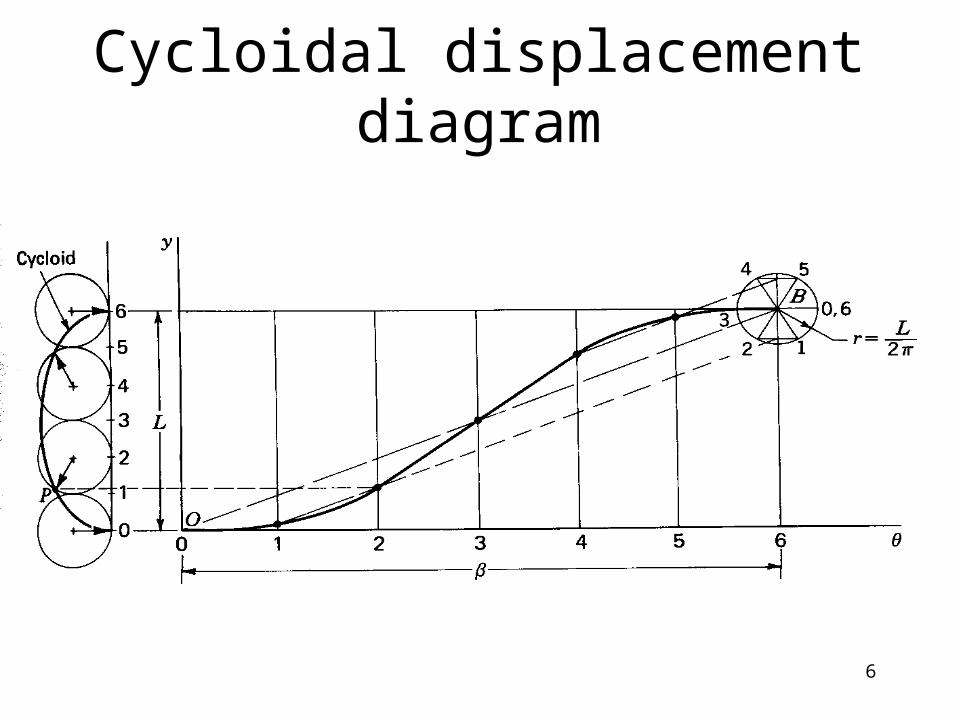
Cycloidal displacement diagram
7
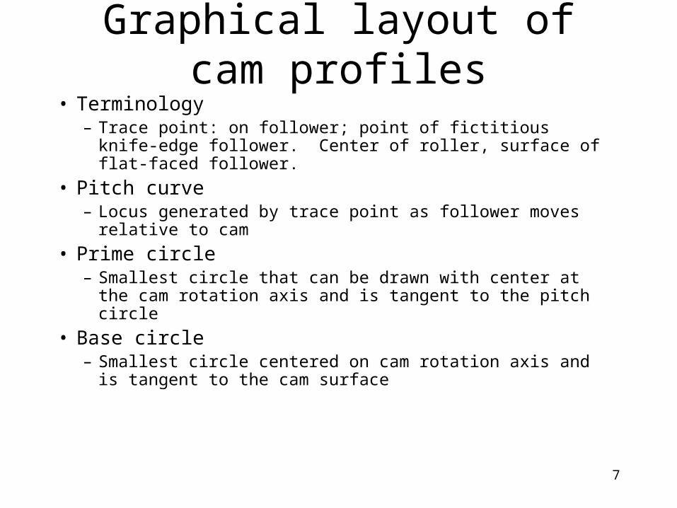
Graphical layout of cam profiles• Terminology
– Trace point: on follower; point of fictitious knife-edge follower. Center of roller, surface of flat-faced follower.
• Pitch curve– Locus generated by trace point as follower moves relative to cam
• Prime circle– Smallest circle that can be drawn with center at the cam rotation
axis and is tangent to the pitch circle
• Base circle– Smallest circle centered on cam rotation axis and is tangent to
the cam surface
8
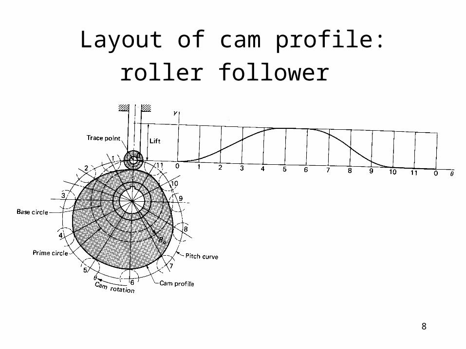
Layout of cam profile: roller follower
9
Constructing cam profile: kinematic inversion principle
• Consider that cam is stationary and that follower rotates in the opposite direction than the cam does in reality
10
11
12
SVAJ diagrams: show displacement, velocity, acceleration versus