Embed Size (px)
Citation preview

1
CFD for Better Understanding of Wind Tunnel Tests
Ning Qin
Department of Mechanical Engineering
University of Sheffield
A presentation at
“International Symposium on Integrating CFD and Experiments”to celebrate the career of Professor Bryan E. Richards, who taught and
introduced me to Computational Aerodynamics
September 8-9, 2003, Glasgow
2
Outline
Introduction
Where are those windward shocks coming from?
Incipient separation criterion
CFD for wind tunnel wall interference corrections
Extrapolation and summary
3
Introduction CFD solutions requires verification
– Algorithm accuracy
– Grid type/resolution sensitivity
– Convergence
CFD models require validation
– Unresolved physics: turbulence
– New physical phenomena: micro/nano-fluidics (gas/liquids), chemical reaction rates, etc.
4
Introduction Demands on wind tunnel investigation
– To understand basic flow physics (its traditional role)
– To validate models used in CFD simulations, which is increasingly more and more difficult/expensive as the application of CFD expands to more and more complicated flow regimes
Wind tunnels have so far helped tremendously in CFD development, can CFD do more in return for wind tunnels to meet the challenges?
– A few examples how this may be achieved
5
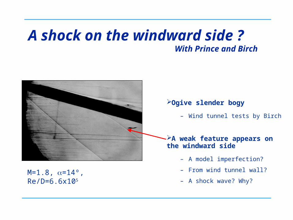
A shock on the windward side ? With Prince and Birch
Ogive slender bogy
– Wind tunnel tests by Birch
A weak feature appears on the windward side
– A model imperfection?
– From wind tunnel wall?
– A shock wave? Why?
M=1.8,=14º, Re/D=6.6x105
6
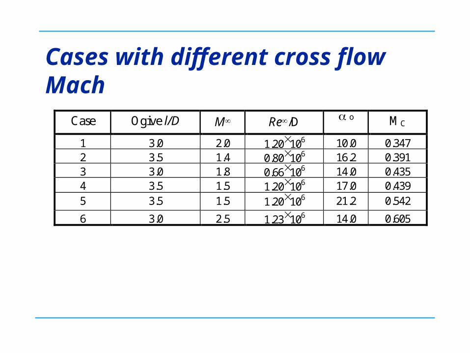
Cases with different cross flow Mach
Case Ogive l/D M Re/D o MC
1 3.0 2.0 1.20106 10.0 0.347 2 3.5 1.4 0.80106 16.2 0.391 3 3.0 1.8 0.66106 14.0 0.435 4 3.5 1.5 1.20106 17.0 0.439 5 3.5 1.5 1.20106 21.2 0.542
6 3.0 2.5 1.23106 14.0 0.605
7
Solution Parabolised Navier-Stokes
Algebraic turbulence models for vortical flows
– Degani-Schiff
– Curvature model
Riemann solver based discretisation
Implicit space marching
Non-adaptive grid: a weakness, which makes the capturing of unknown features difficult
Relatively fine grid can be used due to the efficiency of PNS approach
8
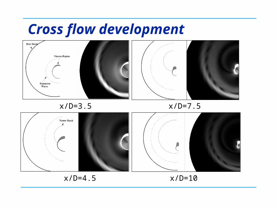
Cross flow development
x/D=3.5
x/D=4.5
x/D=7.5
x/D=10
9
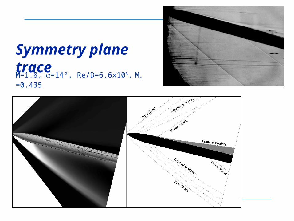
Symmetry plane trace
M=1.8,=14º, Re/D=6.6x105, Mc =0.435
10
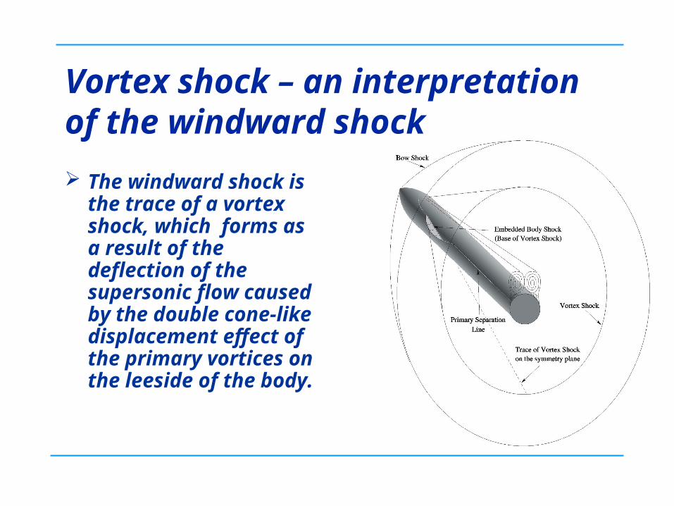
Vortex shock – an interpretation of the windward shock
The windward shock is the trace of a vortex shock, which forms as a result of the deflection of the supersonic flow caused by the double cone-like displacement effect of the primary vortices on the leeside of the body.
11
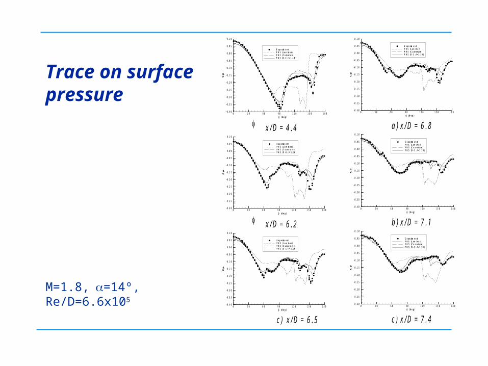
Trace on surface pressure
Cp
0 3 0 6 0 9 0 1 2 0 1 5 0 1 8 0- 0 . 4 0
- 0 . 3 5
- 0 . 3 0
- 0 . 2 5
- 0 . 2 0
- 0 . 1 5
- 0 . 1 0
- 0 . 0 5
0 . 0 0
0 . 0 5
0 . 1 0
E x p e r im e n tP N S ( L a m in a r )P N S ( C u r v a t u r e )P N S ( D - S : f = 1 . 1 0 )
( d e g ) x / D = 4 . 4
Cp
0 3 0 6 0 9 0 1 2 0 1 5 0 1 8 0- 0 . 4 0
- 0 . 3 5
- 0 . 3 0
- 0 . 2 5
- 0 . 2 0
- 0 . 1 5
- 0 . 1 0
- 0 . 0 5
0 . 0 0
0 . 0 5
0 . 1 0
E x p e r im e n tP N S ( L a m in a r )P N S ( C u r v a t u r e )P N S ( D - S : f = 1 . 1 0 )
( d e g ) x / D = 6 . 2
Cp
0 3 0 6 0 9 0 1 2 0 1 5 0 1 8 0- 0 . 4 0
- 0 . 3 5
- 0 . 3 0
- 0 . 2 5
- 0 . 2 0
- 0 . 1 5
- 0 . 1 0
- 0 . 0 5
0 . 0 0
0 . 0 5
0 . 1 0
E x p e r im e n tP N S ( L a m in a r )P N S ( C u r v a t u r e )P N S ( D - S : f = 1 . 1 0 )
( d e g ) c ) x / D = 6 . 5
Cp
0 3 0 6 0 9 0 1 2 0 1 5 0 1 8 0- 0 . 4 0
- 0 . 3 5
- 0 . 3 0
- 0 . 2 5
- 0 . 2 0
- 0 . 1 5
- 0 . 1 0
- 0 . 0 5
0 . 0 0
0 . 0 5
0 . 1 0
E x p e r im e n tP N S ( L a m in a r )P N S ( C u r v a t u r e )P N S ( D - S : f = 1 . 1 0 )
( d e g ) a ) x / D = 6 . 8
Cp
0 3 0 6 0 9 0 1 2 0 1 5 0 1 8 0- 0 . 4 0
- 0 . 3 5
- 0 . 3 0
- 0 . 2 5
- 0 . 2 0
- 0 . 1 5
- 0 . 1 0
- 0 . 0 5
0 . 0 0
0 . 0 5
0 . 1 0
E x p e r im e n tP N S ( L a m in a r )P N S ( C u r v a t u r e )P N S ( D - S : f = 1 . 1 0 )
( d e g ) b ) x / D = 7 . 1
Cp
0 3 0 6 0 9 0 1 2 0 1 5 0 1 8 0- 0 . 4 0
- 0 . 3 5
- 0 . 3 0
- 0 . 2 5
- 0 . 2 0
- 0 . 1 5
- 0 . 1 0
- 0 . 0 5
0 . 0 0
0 . 0 5
0 . 1 0
E x p e r im e n tP N S ( L a m in a r )P N S ( C u r v a t u r e )P N S ( D - S : f = 1 . 1 0 )
( d e g ) c ) x / D = 7 . 4
M=1.8,=14º, Re/D=6.6x105
12
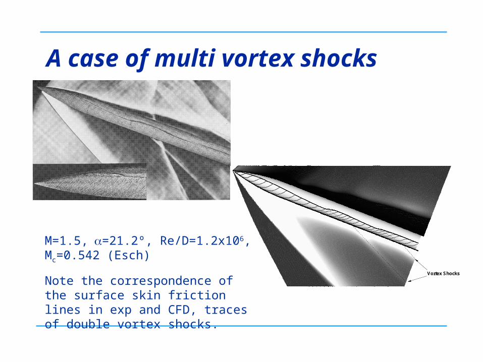
A case of multi vortex shocks
Vortex Shocks
M=1.5,=21.2º, Re/D=1.2x106, Mc=0.542 (Esch)
Note the correspondence of the surface skin friction lines in exp and CFD, traces of double vortex shocks.
13
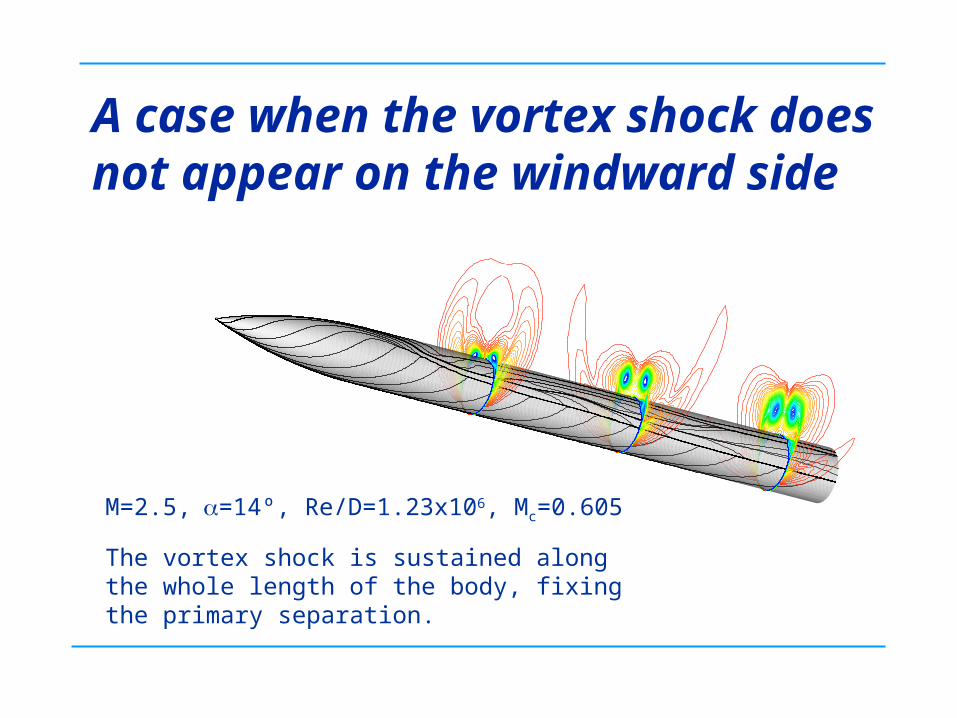
A case when the vortex shock does not appear on the windward side
M=2.5,=14º, Re/D=1.23x106, Mc=0.605
The vortex shock is sustained along the whole length of the body, fixing the primary separation.
14
Summary and Extrapolation
CFD can be used to enhance our understanding of information obtained from wind tunnel tests
Some weak features can be physically significant in design
Flow features unknown beforehand can easily be overshadowed by poor resolution of grid
Critical eyes are required in both experimental tests and CFD simulation
Adaptive gridding can help but need good thinking about the threshold so as not to miss those weak but significant flow features
15
Empirical criteria in aerodynamics Many simple but very useful empirical criteria have
been developed based on wind tunnel tests, e.g. for separation onset, transition to turbulence, etc.
It is interesting to revisit these criteria and possibly extend their usage to broader ranges
Validated CFD may be used as numerical wind tunnels to discover new simple “empirical” criteria and rules
Good understanding of aerodynamics is crucial in extracting/condensing the wind tunnel data or CFD results
16
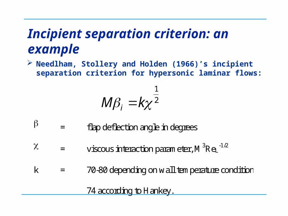
Incipient separation criterion: an example
2
1
kM i = flap deflection angle in degrees
= viscous interaction parameter, M3ReL-1/2
k = 70-80 depending on wall temperature condition
74 according to Hankey.
Needlham, Stollery and Holden (1966)’s incipient separation criterion for hypersonic laminar flows:
17
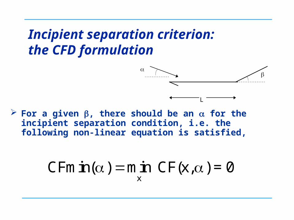
Incipient separation criterion: the CFD formulation
For a given , there should be an for the incipient separation condition, i.e. the following non-linear equation is satisfied,
CFmin( CF(x, ) = 0x
) min
L
18
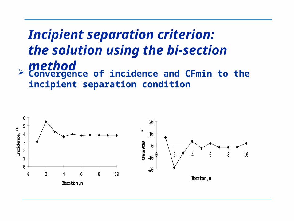
Incipient separation criterion: the solution using the bi-section method
Convergence of incidence and CFmin to the incipient separation condition
0
1
2
3
4
5
6
0 2 4 6 8 10
Iteration, n
Inci
denc
e,
-20
-10
0
10
20
0 2 4 6 8 10
Iteration, n
CFm
inX1
05
19
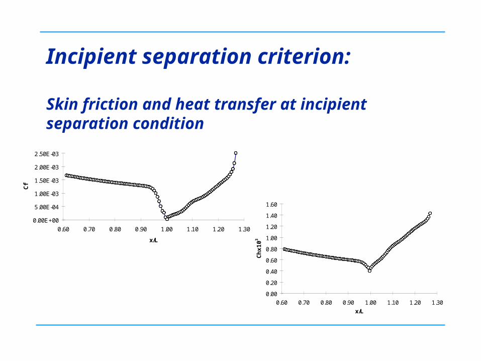
Incipient separation criterion:
Skin friction and heat transfer at incipient separation condition
0.00E+00
5.00E-04
1.00E-03
1.50E-03
2.00E-03
2.50E-03
0.60 0.70 0.80 0.90 1.00 1.10 1.20 1.30
x/L
Cf
0.00
0.20
0.40
0.60
0.80
1.00
1.20
1.40
1.60
0.60 0.70 0.80 0.90 1.00 1.10 1.20 1.30
x/L
Ch
x10
3
20
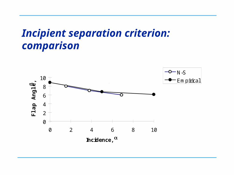
Incipient separation criterion: comparison
0
2
4
6
8
10
0 2 4 6 8 10
Incidence,
Fla
p A
ng
le,
N-S
Empiricalseparated
attached
21
Summary and extrapolation The example demonstrates how CFD can be used to
revisit an aerodynamic empirical rule
CFD may be used to extend the criterion for more general case, e.g. including the wall temperature conditions, turbulent cases, buffet boundary, flow bifurcation, self excited shock oscillation, etc.
If early aerodynamists can derive simple and useful “rules” from wind tunnel data, there is no reason why we cannot do the same combining the two.
Deriving such CFD based “empirical” aerodynamic rules is not easy but can be very rewarding

22
CFD for Wind Tunnel Wall Interference Correction
A series of Cranfield MSc projects with BAE collaborationShadbolt, Farnibanda, Putze, Burton and Cross
Objectives:
– Better use of small tunnels for large models (closer Re to flight conditions);
– Reliable wall interference correction for transonic range, especially, when supercritical flow reaches the tunnel wall;
– Use of modern CFD tools to assess and correct the interference.
23
Background The RAE semi-empirical corrections (Ashill)
The MDA approach (Crites and Rueger)
– modelling of wall boundary conditions for porous walls
– correlation based on vw, Cp and * for a range of porous surfaces
The AEDC approach (Jacocks)
– modelling of wall (1) pre-test prediction (2) measured wall Cp
– correlation between dCp/d and * for AEDC tunnel
The NASA LRC approach
– slotted wall boundary conditions for NTF
24
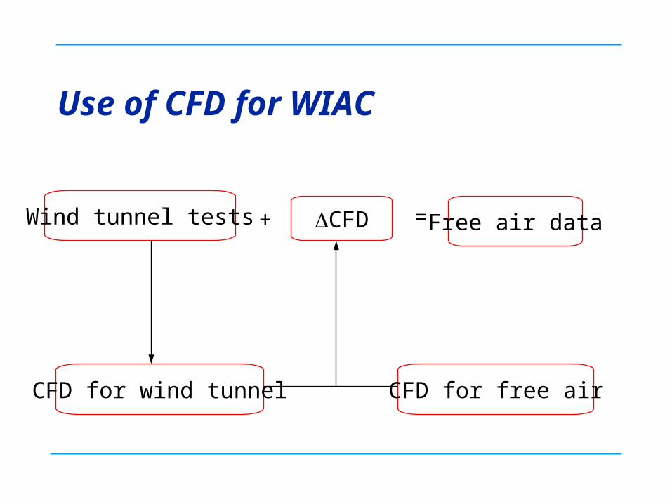
Use of CFD for WIAC
Wind tunnel tests
CFD for free airCFD for wind tunnel
CFD+ = Free air data
25
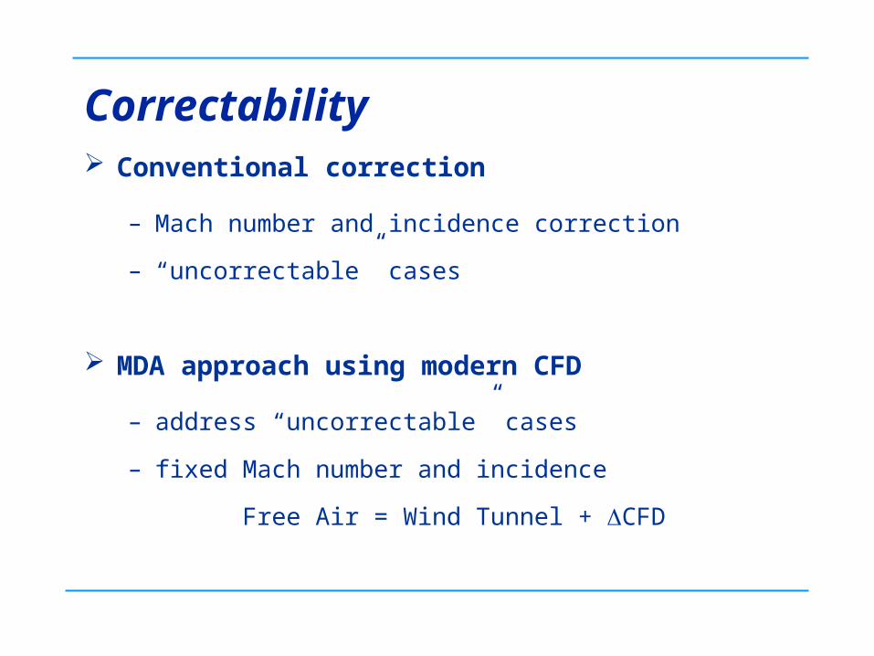
Correctability Conventional correction
– Mach number and incidence correction
– “uncorrectable” cases
MDA approach using modern CFD
– address “uncorrectable” cases
– fixed Mach number and incidence
Free Air = Wind Tunnel + CFD
26
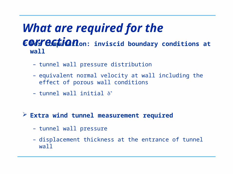
What are required for the correction For computation: inviscid boundary conditions at wall
– tunnel wall pressure distribution
– equivalent normal velocity at wall including the effect of porous wall conditions
– tunnel wall initial *
Extra wind tunnel measurement required
– tunnel wall pressure
– displacement thickness at the entrance of tunnel wall
27
Wall correction: what to match? Conventional correction
– match Cl, correct M and
MDA approach
– match M and correct surface pressure etc.
28
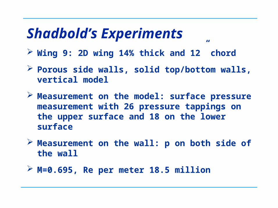
Shadbold’s Experiments Wing 9: 2D wing 14% thick and 12” chord
Porous side walls, solid top/bottom walls, vertical model
Measurement on the model: surface pressure measurement with 26 pressure tappings on the upper surface and 18 on the lower surface
Measurement on the wall: p on both side of the wall
M=0.695, Re per meter 18.5 million
29
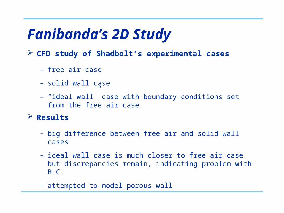
Fanibanda’s 2D Study CFD study of Shadbolt’s experimental cases
– free air case
– solid wall case
– “ideal wall” case with boundary conditions set from the free air case
Results
– big difference between free air and solid wall cases
– ideal wall case is much closer to free air case but discrepancies remain, indicating problem with B.C.
– attempted to model porous wall
30
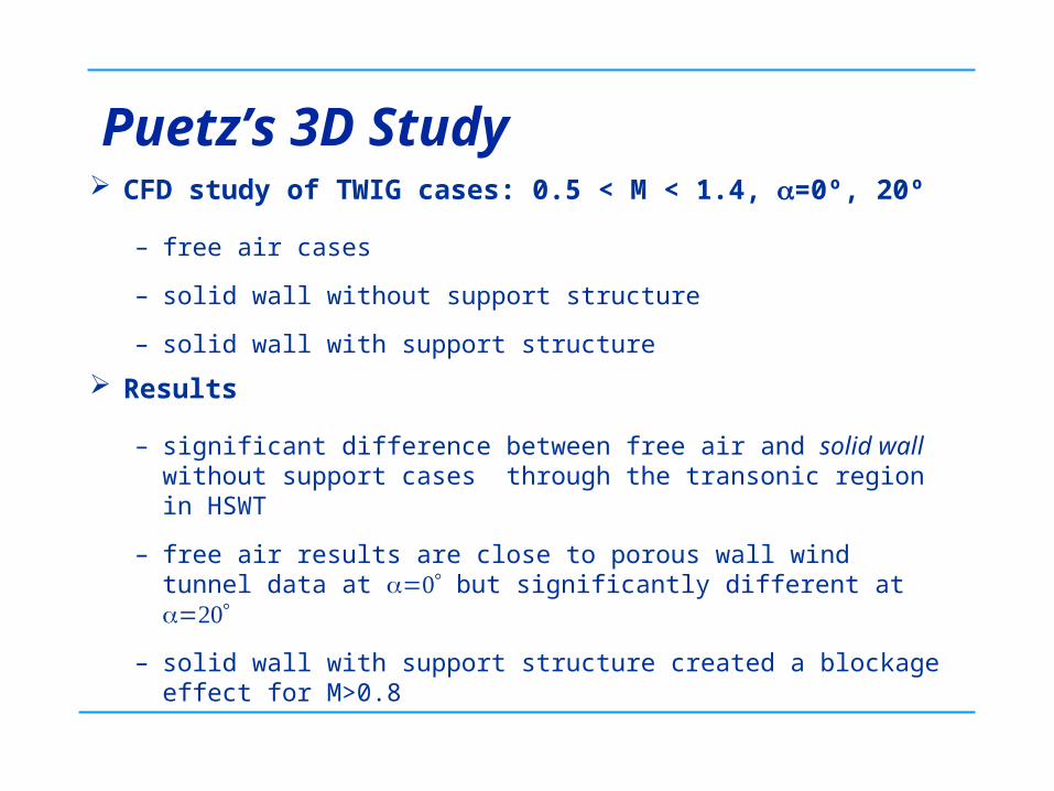
Puetz’s 3D Study CFD study of TWIG cases: 0.5 < M < 1.4, =0º, 20º
– free air cases
– solid wall without support structure
– solid wall with support structure
Results
– significant difference between free air and solid wall without support cases through the transonic region in HSWT
– free air results are close to porous wall wind tunnel data at but significantly different at
– solid wall with support structure created a blockage effect for M>0.8
31
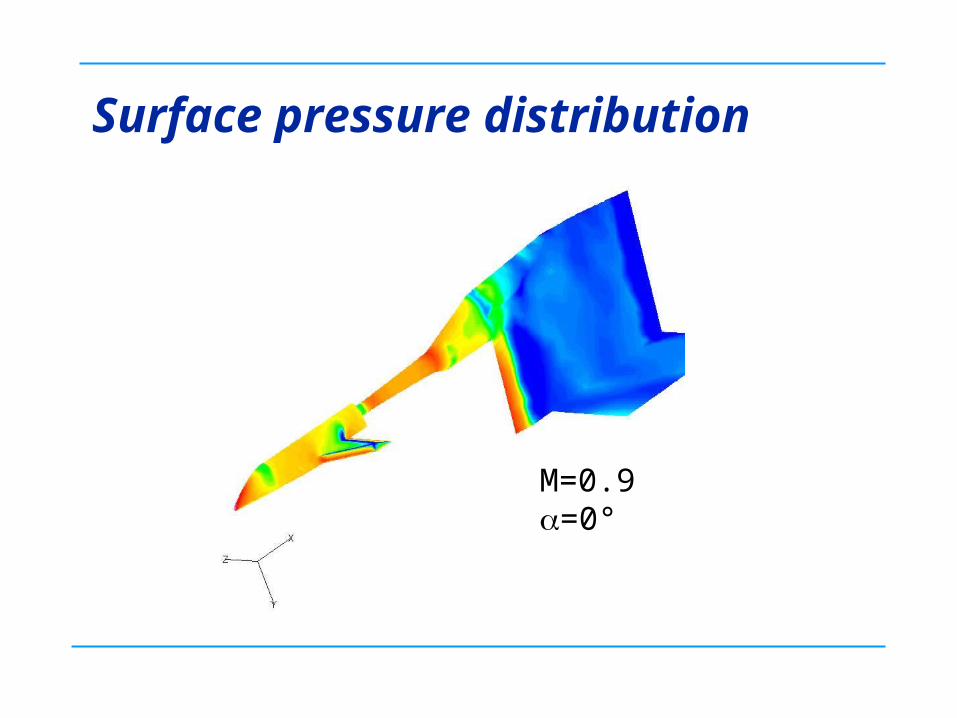
Surface pressure distribution
M=0.9=0°
32
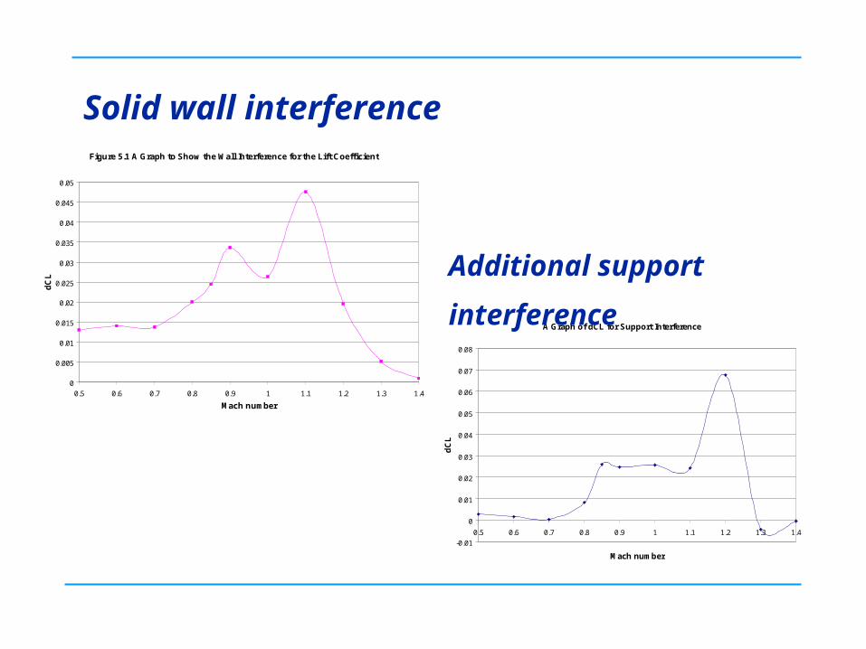
Solid wall interference Figure 5.1 A Graph to Show the Wall Interference for the Lift Coefficient
0
0.005
0.01
0.015
0.02
0.025
0.03
0.035
0.04
0.045
0.05
0.5 0.6 0.7 0.8 0.9 1 1.1 1.2 1.3 1.4
Mach number
dC
L
A Graph of dCL for Support Interference
-0.01
0
0.01
0.02
0.03
0.04
0.05
0.06
0.07
0.08
0.5 0.6 0.7 0.8 0.9 1 1.1 1.2 1.3 1.4
Mach number
dC
L
Additional support interference
33
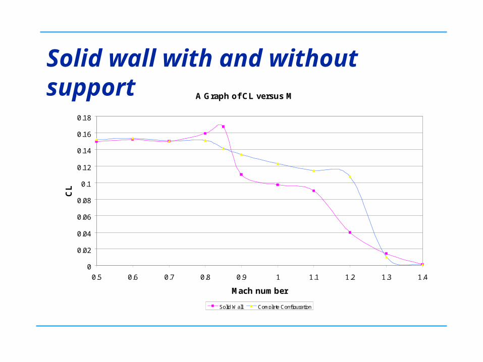
Solid wall with and without supportA Graph of CL versus M
0
0.02
0.04
0.06
0.08
0.1
0.12
0.14
0.16
0.18
0.5 0.6 0.7 0.8 0.9 1 1.1 1.2 1.3 1.4
Mach number
CL
Solid Wall Complete Configuration
34
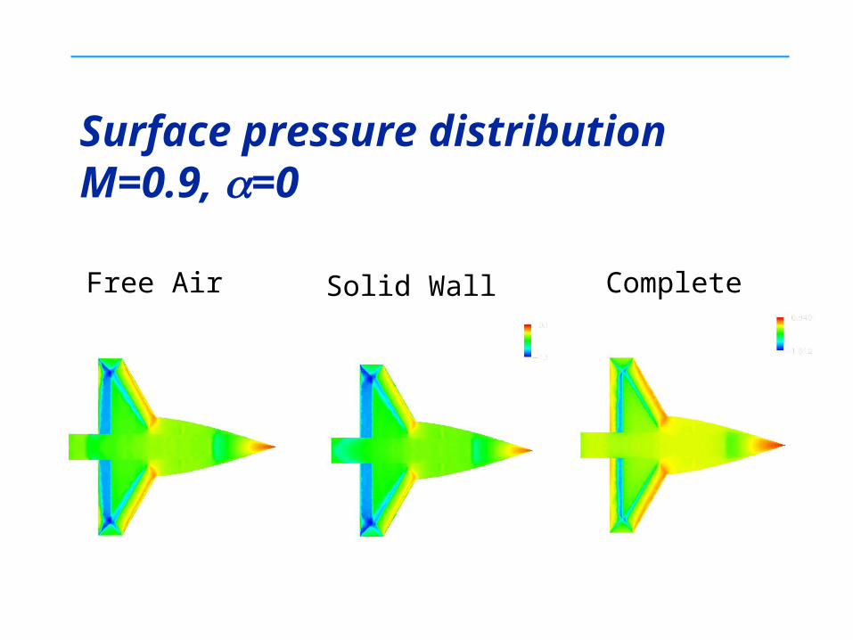
Surface pressure distributionM=0.9, =0
Free Air Solid Wall Complete
35
Summary and Extrapolation The projects confirmed that the wall interference is
most significant in the transonic range (high subsonic).
The model support structure has a strong interference at low supersonic range.
CFD can be used for WIAC improving the accuracy and the effective range of Reynolds number in wind tunnel tests (larger models in existing tunnels).
Require further development of proper CFD boundary condition for the WIAC study.
36
Conclusion
The three examples presented here highlight some potential use of CFD to help wind tunnel experimental investigation.
A lot needs to be done to achieve this!