Embed Size (px)
Citation preview
1
Chapter 14
Mass-Storage Structure

2
Disk StructureDisk drives are addressed as large 1-dimensional arrays of logical blocks, where the logical block is the smallest unit of transfer. The 1-dimensional array of logical blocks is mapped into the sectors of the disk sequentially.
Sector 0 is the first sector of the first track on the outermost cylinder.
Mapping proceeds in order through that track, then the rest of the tracks in that cylinder, and then through the rest of the cylinders from outermost to innermost.
磁碟結構

3
Disk SchedulingThe operating system is responsible for using hardware efficiently — for the disk drives, this means having a fast access time and disk bandwidth.Access time has two major components
Seek time is the time for the disk are to move the heads to the cylinder containing the desired sector.
Rotational latency is the additional time waiting for the disk to rotate the desired sector to the disk head.
Disk bandwidth is the total number of bytes transferred, divided by the total time between the first request for service and the completion of the last transfer.
旋轉延遲
尋找時間
磁碟頻寬
磁碟排程

4
Multiple Choices Question:( )Two major determining factors
of disk access time is the _________ and the rotational latency. (A) around time (B) feedback time (C) seek time (D) execution time (E) wait time
Ans: C
5
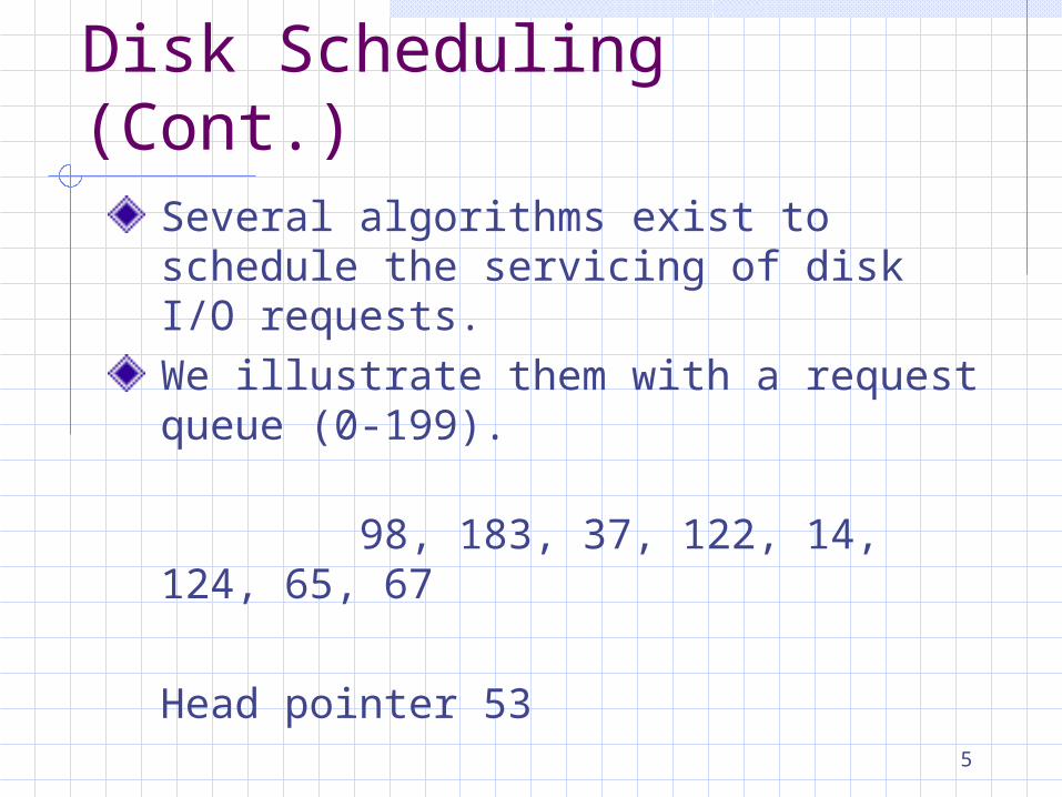
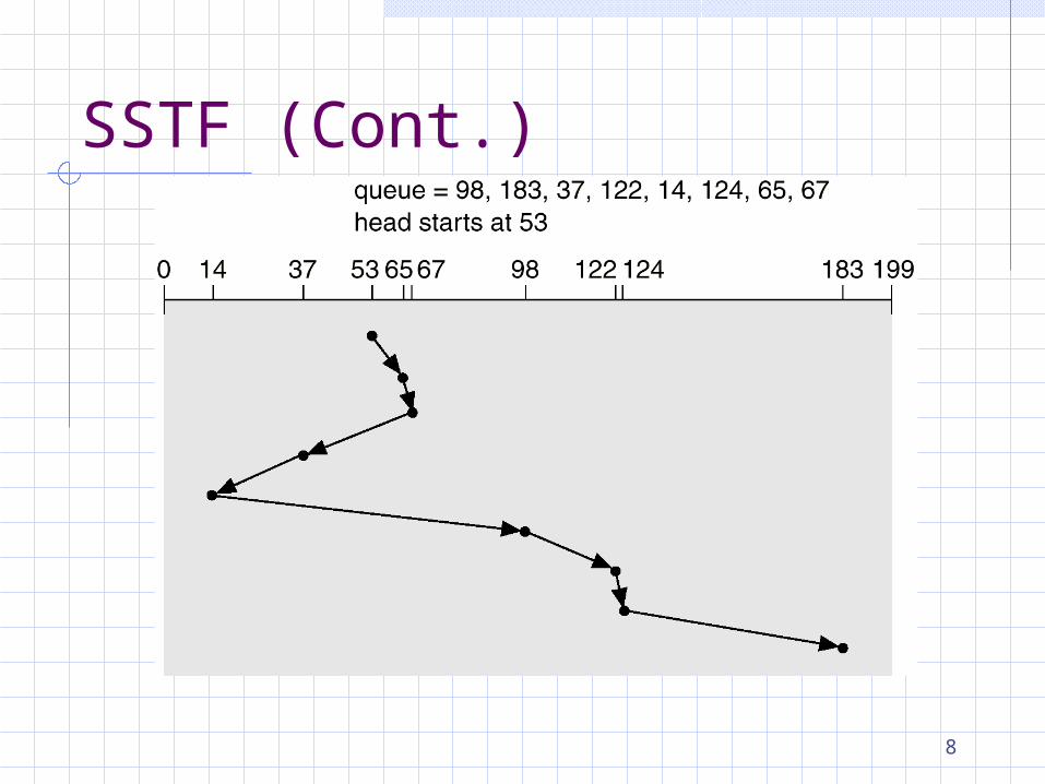
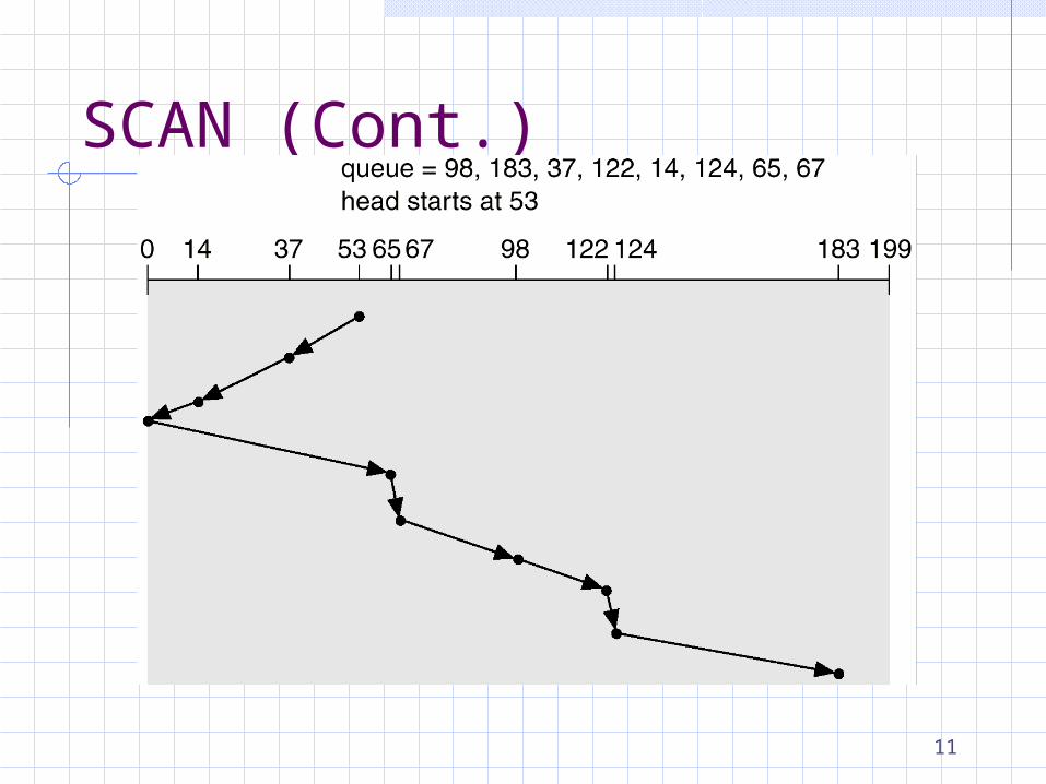
Disk Scheduling (Cont.)Several algorithms exist to schedule the servicing of disk I/O requests. We illustrate them with a request queue (0-199).
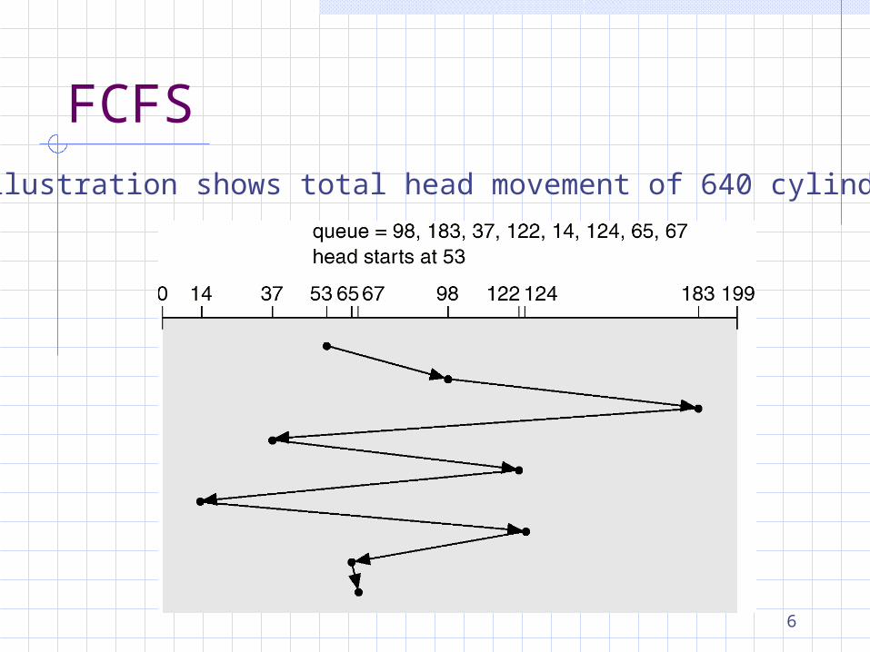
98, 183, 37, 122, 14, 124, 65, 67
Head pointer 53
6
FCFSIllustration shows total head movement of 640 cylinders.
7
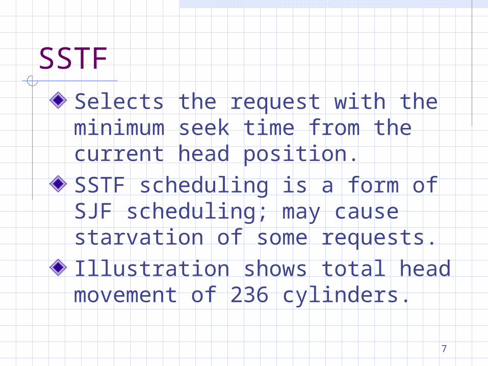
SSTFSelects the request with the minimum seek time from the current head position.SSTF scheduling is a form of SJF scheduling; may cause starvation of some requests.Illustration shows total head movement of 236 cylinders.
8
SSTF (Cont.)
9
SCANThe disk arm starts at one end of the disk, and moves toward the other end, servicing requests until it gets to the other end of the disk, where the head movement is reversed and servicing continues.Sometimes called the elevator algorithm.Illustration shows total head movement of 208 cylinders.

10
Multiple Choices Question:( ) Which algorithm listed below is
also called “elevator algorithm”? (A) SCAN (B) SSTF (C) LOOK (D) C-LOOK (E) FCFS
Ans: A
11
SCAN (Cont.)
12
C-SCANProvides a more uniform wait time than SCAN.The head moves from one end of the disk to the other. servicing requests as it goes. When it reaches the other end, however, it immediately returns to the beginning of the disk, without servicing any requests on the return trip.Treats the cylinders as a circular list that wraps around from the last cylinder to the first one.
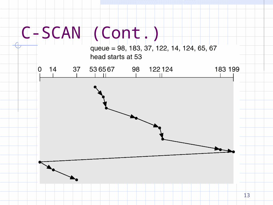
13
C-SCAN (Cont.)
14
C-LOOKVersion of C-SCANArm only goes as far as the last request in each direction, then reverses direction immediately, without first going all the way to the end of the disk.
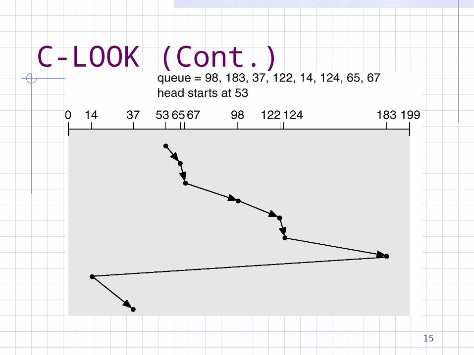
15
C-LOOK (Cont.)
16
Selecting a Disk-Scheduling Algorithm
SSTF is common and has a natural appealSCAN and C-SCAN perform better for systems that place a heavy load on the disk.Performance depends on the number and types of requests.Requests for disk service can be influenced by the file-allocation method.The disk-scheduling algorithm should be written as a separate module of the operating system, allowing it to be replaced with a different algorithm if necessary.Either SSTF or LOOK is a reasonable choice for the default algorithm.
17
True-False Question:( )Either FCFS or LOOK is
a reasonable choice for the default disk scheduling algorithm.
Ans: X
18
Disk Management Disk Formatting Boot Block Bad Block
§14.3
19
Disk FormattingLow-level formatting: Before a disk can store data, it must be divided into sectors that the disk controller can read and write. It fills the disk with a special data structure for each sector.
header data area (usually 512 bytes) trailer
Consists of
§14.3.1
20
Error-correcting code (ECC)
The header and the trailer contain information used by the disk controller, such as sector number and ECC.ECC: value calculated from all the bytes in the data area. Can be used to calculate the correct value if few bits of data have been corrupted.The controller automaticaly does the ECC processing whenever a sector is read and written.
21
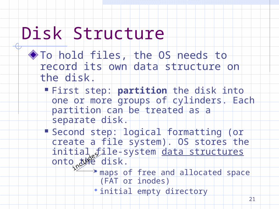
Disk StructureTo hold files, the OS needs to record its own data structure on the disk.
First step: partition the disk into one or more groups of cylinders. Each partition can be treated as a separate disk.
Second step: logical formatting (or create a file system). OS stores the initial file-system data structures onto the disk.
maps of free and allocated space(FAT or inodes)
initial empty directoryincludes
22
Boot BlockInitial (tiny) bootstrap loader program stored in read-only memory (ROM) to bring in a full bootstrap program from disk.The full bootstrap program is stored in a partition called the boot block, at a fixed location on the disk.A disk that has a boot partition is called a boot disk or system disk.
§14.3.2
23
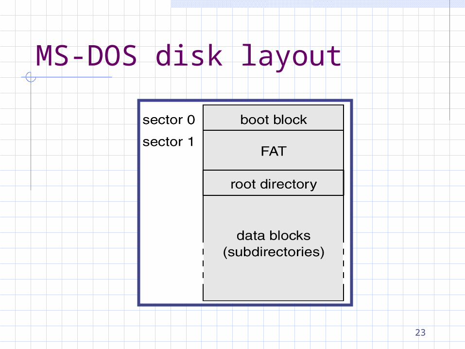
MS-DOS disk layout

24
Bad BlocksFrequently, one or more sectors become defected... Bad blocks. They are handled differently:
IDE controller: handled manually.When formatting, also scans the disk to find bad blocks. If bad blocks are found, it is remembered in the FAT. Later bad blocks must be found by manually run chkdsk command to search.
§14.3.3
25
Sector Sparing SCSI controller:
The controller maintains a list of bad blocks on the disk, which is initialized during formatting and updated over the life of the disk.Formatting also set aside spare sectors for replacing bad sectors logically...sector sparing or forwarding.

26
Sector SparingA typical bad-sector transaction:
OS read a logical block Controller calculates the ECC and
finds it bad. Reported to the OS. During next reboot, the SCSI
controller replace the bad sector with a spare.
After that, requests this logical block is translated into the replacement sector’s address by the controller.

27
Sector SparingRedirection by the controller could invalidate any optimization by the OS’s disk-scheduling algorithm!Provide a few spare sectors in each cylinder, and a spare cylinder as well.When a bad block is remapped, the controller uses a spare sector from the same cylinder, if possible.
28
Sector SlippingSuppose logical block 17 becomes defective, and the first available spare follows sector 202.Sector slipping would remap all the sectors from 17 to 202, moving them all down one spot.This would frees up sector 18, so 17 can be mapped to it.
29
Swap-Space ManagementVirtual memory uses disk space as an extension of main memory.Decreases system performance but provide better throughput for virtual-memory system.
§14.4

30
Swap-Space UseSwapping uses swap space to hold the entire process image.Paging stores pages that have been pushed out of main memory.UNIX allow multiple swap spaces put on separate disks so the loading placed on the I/O system by paging and swapping can be spread over the system’s I/O devices.It is safer to overestimate than to underestimate swap space.
§14.4.1
31
Swap-Space LocationSwap space can be from normal file system or can be in a separate disk partition.
1. From normal file system: inefficient.Navigating the directory structure takes time and extra disk accesses. External fragmentation can greatly
increase swapping times by forcing multiple seeks during reading or writing of a process image.
§14.4.2
32
Swap-Space Location2. From separate disk partition: a
separate swap-space storage manager is used to allocate and deallocate the blocks.
Manager optimized for speed, not for storage efficiency.Although internal fragmentation may increase, it is acceptable because data in the swap space generally live for much shorter amounts of time than do files in the file system.
33
Swap-Space Management Example -- UNIX
UNIX 4.3 BSD preallocate swap space to a process when it is started.Enough space is set aside to hold the program, known as the text pages or text segment, and the data segemnt of the process.File system is consulted only once for each text page.
§14.4.3

34
Swap-Space Management Example -- UNIX
Two swap maps per process are used by the kernel to track swap-space use.The text segment is a fixed size of 512 KB chunks allocated, except the final chunk for last page.
§14.4.3
35
Swap-Space Management Example -- UNIX
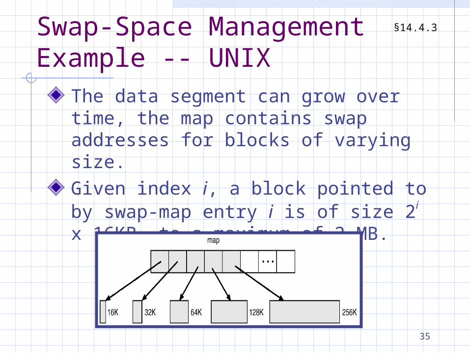
The data segment can grow over time, the map contains swap addresses for blocks of varying size.Given index i, a block pointed to by swap-map entry i is of size 2i x 16KB, to a maximum of 2 MB.
§14.4.3
36
Swap-Space Management Example -- UNIX
When a process tries to grow its data segment beyond the final allocated block in its swap area, the OS allocates another double-sized block.This scheme results in small processes using only small blocks. It also minimizes fragmentation.
§14.4.3
37
Swap-Space Management Example – Solaris 1
Thrown away pages if selected for pageout.More efficient to reread a page from the file system than to write it to swap space and then to reread it from there.Solaris 2 allocates swap space only when a page is forced out of physical memory, rather than when the virtual-memory page is first created.
§14.4.3
38
RAID StructureBefore, disk-organization techniques called redundant arrays of inexpensive disks (RAID) composed of small cheap disks as a cost-effective alternative to large, expensive disks.Today, RAIDs are used for their higher reliability and higher data-transfer rate, rather than for economic reasons.
§14.5