Embed Size (px)
Citation preview

1
Chapter 2

2
Chapter 2
2.1 Introduction• Language of the Machine
• We’ll be working with the MIPS instruction set architecture
– similar to other architectures developed since the 1980's
– Almost 100 million MIPS processors manufactured in 2002
– used by NEC, Nintendo, Cisco, Silicon Graphics, Sony, …1400
1300
1200
1100
1000
900
800
700
600
500
400
300
200
100
01998 2000 2001 20021999
Other
SPARC
Hitachi SH
PowerPC
Motorola 68K
MIPS
IA-32
ARM

3
2.2 Operations of the Computer Hardware
• All instructions have 3 operands• Operand order is fixed (destination first)
Example:
C code: a = b + c
MIPS ‘code’: add a, b, c #the sum of b and c is placed in a.
(we’ll talk about registers in a bit)
“The natural number of operands for an operation like addition is three…requiring every instruction to have exactly three operands, no more and no less, conforms to the philosophy of keeping the hardware simple”
4
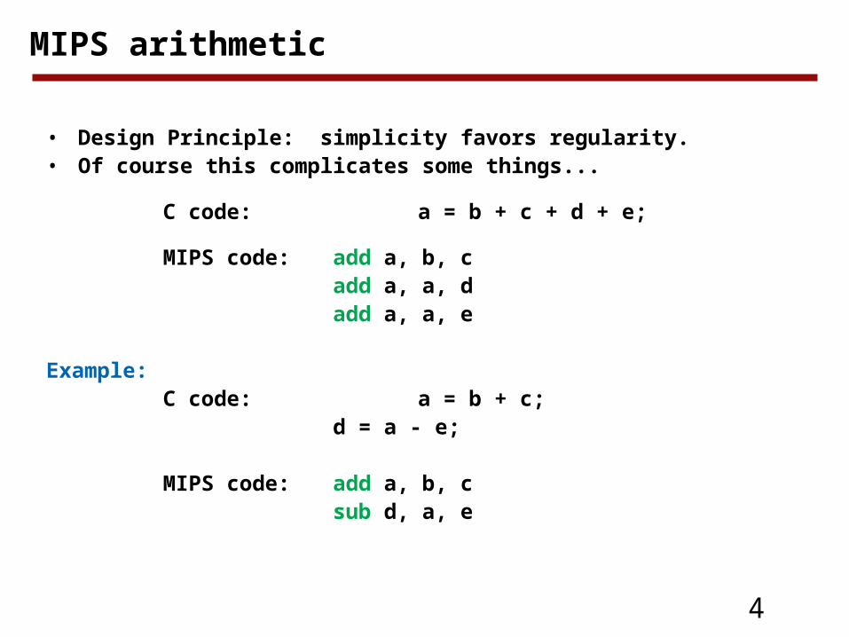
MIPS arithmetic
• Design Principle: simplicity favors regularity. • Of course this complicates some things...
C code: a = b + c + d + e;
MIPS code: add a, b, cadd a, a, dadd a, a, e
Example:C code: a = b + c;
d = a - e;
MIPS code: add a, b, csub d, a, e
5
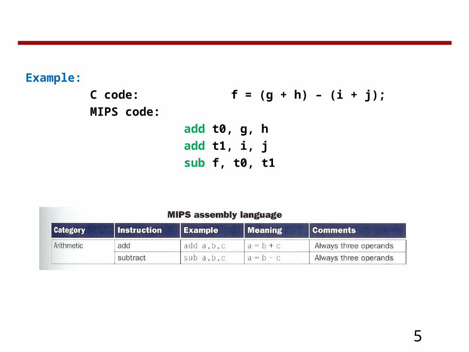
Example:
C code: f = (g + h) – (i + j);
MIPS code:
add t0, g, h
add t1, i, j
sub f, t0, t1
6
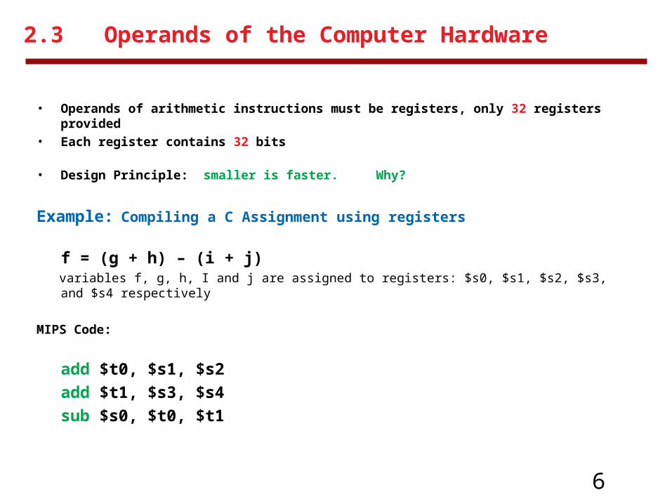
2.3 Operands of the Computer Hardware
• Operands of arithmetic instructions must be registers, only 32 registers provided
• Each register contains 32 bits
• Design Principle: smaller is faster. Why?
Example: Compiling a C Assignment using registers
f = (g + h) – (i + j) variables f, g, h, I and j are assigned to registers: $s0, $s1, $s2, $s3, and $s4 respectively
MIPS Code:
add $t0, $s1, $s2
add $t1, $s3, $s4
sub $s0, $t0, $t1

7
Memory Operands
Processor I/O
Control
Datapath
Memory
Input
Output
Data Transfer instructions
• Arithmetic instructions operands must be registers, — only 32 registers provided
• Compiler associates variables with registers
• What about programs with lots of variables

8
Memory Organization
• Viewed as a large, single-dimension array, with an address.
• A memory address is an index into the array
• "Byte addressing" means that the index points to a byte of memory.
0
1
2
3
4
5
6
...
8 bits of data
8 bits of data
8 bits of data
8 bits of data
8 bits of data
8 bits of data
8 bits of data
9
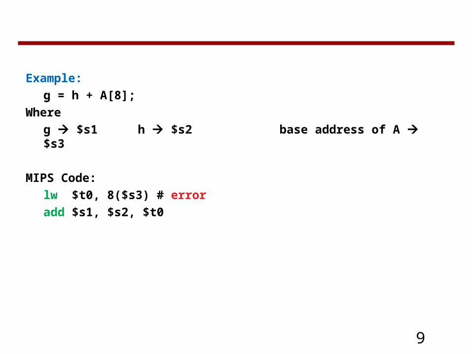
Example:
g = h + A[8];
Where
g $s1 h $s2 base address of A $s3
MIPS Code:
lw $t0, 8($s3) # error
add $s1, $s2, $t0

10
Hardware Software Interface
Alignment restriction• Bytes are nice, but most data items use larger "words"• For MIPS, a word is 32 bits or 4 bytes.
• 232 bytes with byte addresses from 0 to 232-1• 230 words with byte addresses 0, 4, 8, ... 232-4• Words are aligned
i.e., what are the least 2 significant bits of a word address?
0
4
8
12
...
32 bits of data
32 bits of data
32 bits of data
32 bits of data
Registers hold 32 bits of data

11
Instructions
• Load and store instructions
Example:
C code: A[12] = h + A[8];where: h $s2 base address of A $s3
MIPS code: lw $t0, 32($s3)add $t0, $s2, $t0sw $t0, 48($s3)
• Can refer to registers by name (e.g., $s2, $t2) instead of number• Store word has destination last• Remember arithmetic operands are registers, not memory!
Can’t write: add 48($s3), $s2, 32($s3)
12
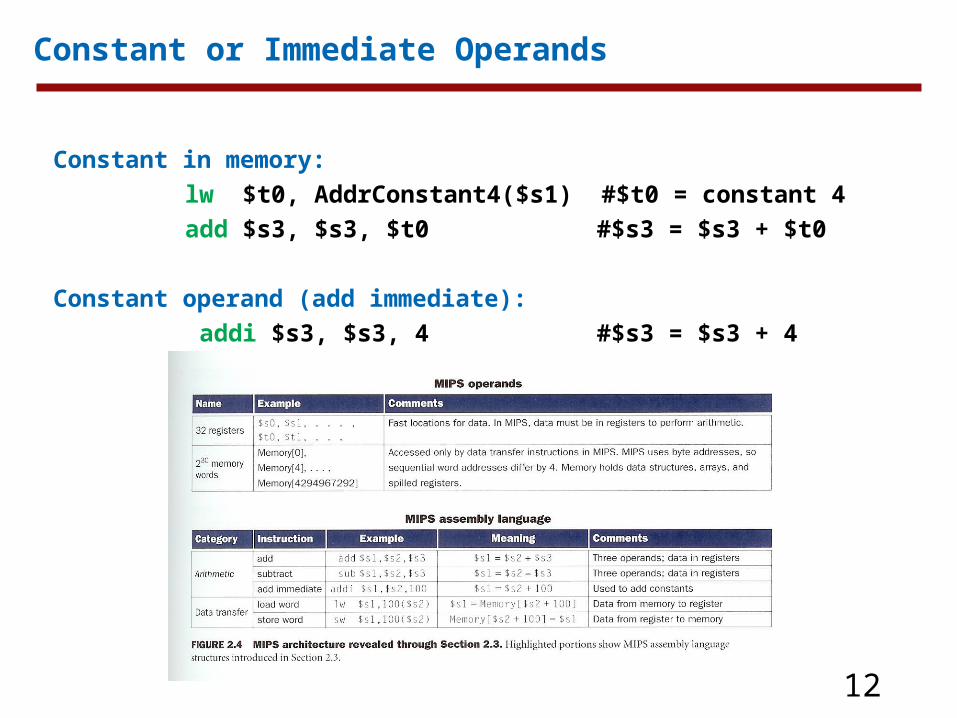
Constant or Immediate Operands
Constant in memory:
lw $t0, AddrConstant4($s1) #$t0 = constant 4
add $s3, $s3, $t0 #$s3 = $s3 + $t0
Constant operand (add immediate):
addi $s3, $s3, 4 #$s3 = $s3 + 4

13
So far we’ve learned:
• MIPS— loading words but addressing bytes— arithmetic on registers only
• Instruction Meaning
add $s1, $s2, $s3 $s1 = $s2 + $s3sub $s1, $s2, $s3 $s1 = $s2 – $s3lw $s1, 100($s2) $s1 = Memory[$s2+100] sw $s1, 100($s2) Memory[$s2+100] = $s1

14
• Instructions, like registers and words of data, are also 32 bits long
Example: add $t0, $s1, $s2– registers have numbers, $t0=8, $s1=17, $s2=18
Instruction Format (MIPS Fields):
000000 10001 10010 01000 00000 100000
op rs rt rd shamt funct
op: opcode.
rs: first register source
rt: second register source
rd: register destination
shamt: shift amount
funct: function code
2.4 Representing Instructions in the Computer
6 bits 5 bits 5 bits 5 bits 5 bits 6 bits

15
• Consider the load-word and store-word instructions,
– What would the regularity principle have us do?
– New principle: Good design demands a compromise
• Introduce a new type of instruction format
– I-type for data transfer instructions
– other format was R-type for register
• Example: lw $t0, 32($s2)
35 18 8 32
op rs rt constant or address
• Where's the compromise?
R-format and I-format
6 bits 5 bits 5 bits 16 bits

16
Translating MIPS Assembly into Machine Language
Example:
A[300] = h + A[300];
$s2 $t1
is compiled into:
lw $t0, 1200($t1)
add $t0, $s2, $t0
sw $t0, 1200($t1)
----------
t0 8 t1 9 s2 18
100011 01001 01000 0000 0100 1011 0000
000000 10010 01000 01000 00000 100000
101011 01001 01000 0000 0100 1011 0000

17
So far we’ve learned:

18
• Instructions are bits
• Programs are stored in memory — to be read or written just like data
• Fetch & Execute Cycle
– Instructions are fetched and put into a special register
– Bits in the register "control" the subsequent actions
– Fetch the “next” instruction and continue
memory for data, programs, compilers, editors, etc.
Stored Program Concept

19
2.5 Logical Operations
Example:
sll $t2, $s0, 4 # reg $t2 = reg $s0 << 4 bits
$s0 contained:
0000 0000 0000 0000 0000 0000 0000 1001
After executions:
0000 0000 0000 0000 0000 0000 1001 0000
Op Rs Rt Rd shamt funct
0 0 16 10 4 0
$t2$s0

20
Logical opeartions: and or nor
$t1: 0000 0000 0000 0000 0011 1100 0000 0000 $t2: 0000 0000 0000 0000 0000 1101 0000 0000 $t1 & $t2 0000 0000 0000 0000 0000 1100 0000 0000 $t1 | $t2 0000 0000 0000 0000 0011 1101 0000 0000
$t1: 0000 0000 0000 0000 0011 1100 0000 0000 $t3: 0000 0000 0000 0000 0000 0000 0000 0000 ~($t1 | $t3) 1111 1111 1111 1111 1100 0011 1111 1111
and $t0, $t1, $t2 # $t0 = $t1 & $t2or $t0, $t1, $t2 # $t0 = $t1 | $t2nor $t0, $t1, $t3 # $t0 = ~($t1 | $t3)
• andi: and immediate• ori : or immediate• No immediate version for NOR (its main use is to invert the bits of a single
operand.

21
So far we’ve learned:

22
• Decision making instructions– alter the control flow,– i.e., change the "next" instruction to be executed
• MIPS conditional branch instructions:
beq $t0, $t1, Label bne $t0, $t1, Label
• Example: if (i==j) h = i + j; i$s0 i$s1 h$s3
bne $s0, $s1, Labeladd $s3, $s0, $s1
Label: ....
2.6 Instruction for Making Decisions
23
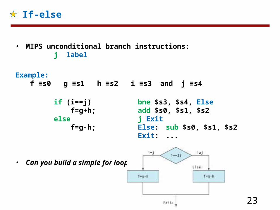
• MIPS unconditional branch instructions:j label
Example: f ≡s0 g ≡s1 h ≡s2 i ≡s3 and j ≡s4
if (i==j) bne $s3, $s4, Else f=g+h; add $s0, $s1, $s2else j Exit f=g-h; Else: sub $s0, $s1, $s2
Exit: ...
• Can you build a simple for loop?
If-else

24
loops
Example: Compiling a while loop in C:
While (save[i] == k)
i += 1;
Assume: i ≡s3 k ≡s5 base-of A[]≡s6
Loop: sll $t1, $s3, 2
add $t1, $t1, $s6
lw $$t0, 0($t1)
bne $t0, $$5, Exit
add $s3, $s3, 1
j loop
Exit:

25
So far:
• Instruction Meaning
add $s1,$s2,$s3 $s1 = $s2 + $s3sub $s1,$s2,$s3 $s1 = $s2 – $s3lw $s1,100($s2) $s1 = Memory[$s2+100] sw $s1,100($s2) Memory[$s2+100] = $s1bne $s4,$s5,L Next instr. is at Label if $s4 ≠ $s5beq $s4,$s5,L Next instr. is at Label if $s4 = $s5j Label Next instr. is at Label
• Formats:
op rs rt rd shamt funct
op rs rt 16 bit address
op 26 bit address
R
I
J

26
Continue
set on less than instruction:
slt $t0, $s3, $s4
slti $t0, $s2, 10
Means:
if($s3<$s4) $t0=1;
else $t0=0;

27
2.7 Supporting Procedures in Computer Hardware
• $a0-$a3: four arguments• $v0-Sv1: two value registers in which to return values• $ra: one return address register• jal: jump and save return address in $ra.• jr $ra: jump to the address stored in register $ra.
Using More Registers• Spill registers to memory• Stack• $sp

28
Example: Leaf procedure
int leaf_example(int g, int h, int i, int j)
{
int f;
f=(g+h)-(i+j);
return f;
}
leaf_example:
addi $sp, $sp, -12
sw $t1, 8($sp)
sw $t0, 4($sp)
sw $s0, 0($sp)
add $t0, $a0, $a1
add $t1, $a2, $a3
sub $s0, $t0, $t1
add $v0, $s0, $zero
lw $s0, 0($sp)
lw $t0, 4($sp)
lw $t1, 8($sp)
addi $sp, $sp, 12
jr $ra

29
Nested Procedures
int fact (int n){
if(n<1) return (1);else return (n*fact(n-1));
}
fact:addi $sp, $sp, -8sw $ra, 4($sp)sw $a0, 0($sp)
slti $t0, $a0, 1beq $t0, $zero, L1
addi $v0, $zero, 1addi $sp, $sp, 8jr $ra
L1: addi $a0, $a0, -1 jal fact
lw $a0, 0($sp)lw $ra, 4($sp)addi $sp, $sp, 8
mul $v0, $a0, $v0jr $ra

30
Allocating Space for New Data on the Stack
• Stack is also used to store Local variables that do not fit in registers (arrays or structures)
• Procedure frame (activation record)
• Frame Pointer

31
Allocating Space for New Data on the Heap
• Need space for static variables and dynamic data structures (heap).

32
Policy of Use Conventions
Name Register number Usage$zero 0 the constant value 0$v0-$v1 2-3 values for results and expression evaluation$a0-$a3 4-7 arguments$t0-$t7 8-15 temporaries$s0-$s7 16-23 saved$t8-$t9 24-25 more temporaries$gp 28 global pointer$sp 29 stack pointer$fp 30 frame pointer$ra 31 return address
Register 1 ($at) reserved for assembler, 26-27 for operating system

33
2.8 Communicating with People
• For text process, MIPS provides instructions to move bytes (8 bits ASCII):
lb $t0, 0($sp)
Load a byte from memory, placing it in the rightmost 8 bits of a register.
sb $t0, 0($gp)
Store byte (rightmost 8 bits of a register) in to memory.
• Java uses Unicode for characters: 16 bits to represent characters:
lh $t0, 0($sp) #Read halfword (16 bits) from source
sh $t0, 0($gp) #Write halfword (16 bits) to destination

34
Example:
void strcpy(char x[], char y[])
{
int i;
i=0;
while((x[i]=y[i])!=‘\0’)
i+=1;
}
strcpy:addi $sp, $sp, -4
sw $s0, 0($sp)
add $s0, $zero, $zero
L1:add $t1, $s0, $a1
lb $t2, 0($t1)
add $t3, $s0, $a0
sb $t2, 0($t3)
beq $t2, $zero, L2
addi $s0, $s0, 1
j L1
L2:lw $s0, 0($sp)
addi $sp, $sp, 4
jr $ra

35
2.9 MIPS Addressing for 32-Bit Immediates and Address
32-Bit Immediate Operands• load upper immediate lui to set the upper 16 bits of a constant in a register.
lui $t0, 255 # $t0 is register 8:
001111 00000 01000 0000 0000 1111 1111
0000 0000 1111 1111 0000 0000 0000 0000
Contents of register $t0 after executing: lui $t0, 255

36
Example: loading a 32-Bit Constant
What is the MIPS assembly code to load this 32-bit constant into register $s0
0000 0000 0011 1101 0000 1001 0000 0000
lui $s0, 61
The value of $s0 afterward is:
0000 0000 0011 1101 0000 0000 0000 0000
ori $s0, $s0, 2304
The final value in register $s0 is the desire value:
0000 0000 0011 1101 0000 1001 0000 0000

37
Addressing in Branches and Jumps
• jump addressing
j 10000 #go to location 10000
5 16 17 Exit
2 10000
6 bits 26 bits
• Unlike the jump, the conditional branch must specify two operands:
bne $s0, $s1, Exit # go to Exit if $s0 ≠ $s1
• No program could be bigger than 216, which is far too small• Solution: PC-relative addressing
Program counter = PC + Branch address
PC points to the next instruction to be executed.
6 bits 5 bits 5 bits 16 bits

38
Examples:
Showing Branch Offset in Machine Language
loop: sll $t1, $s3, 2add $t1, $t1, $s6lw $t0, 0($t1)bne $t0, $s5, Exitaddi $s3, $s3, 1j Loop
Exit:
80000 0 0 19 9 2 0
80004 0 9 22 9 0 32
80008 35 9 8 0
80012 5 8 21 2
80016 8 19 19 1
80020 2 2000
80024 ………
while (save[i] == k)
i += 1;

39
Example
Branching Far Away
Given a branch on register $s0 being equal to $s1,
beq $S0, $s1, L1replace it by a pair of instructions that offers a much greater branching distance.
These instructions replace the short-address conditional branch:
bne $s0, $s1, L2
j L1
L2: ...

40
MIPS Addressing Modes Summary
1. Register addressing
2. Base or displacement addressing
3. Immediate addressing
4. PC-relative addressing
5. Pseudodirect addressing: 26 bits concatenated with the upper bits of the PC. Byte Halfword Word
Registers
Memory
Memory
Word
Memory
Word
Register
Register
1. Immediate addressing
2. Register addressing
3. Base addressing
4. PC-relative addressing
5. Pseudodirect addressing
op rs rt
op rs rt
op rs rt
op
op
rs rt
Address
Address
Address
rd . . . funct
Immediate
PC
PC
+
+

41
Decoding Machine Language
What is the assembly language corresponding to this machine code:
00af8020hex
0000 0000 1010 1111 1000 0000 0010 0000
From fig 2.25, it is an R-format instruction
000000 00101 01111 10000 00000 100000
from fig 2.25, Represent an add instruction
add $s0, $a1, $t7

42
• Small constants are used quite frequently (50% of operands) e.g., A = A + 5;
B = B + 1;C = C - 18;
• Solutions? Why not?– put 'typical constants' in memory and load them. – create hard-wired registers (like $zero) for constants like one.
• MIPS Instructions:
addi $29, $29, 4slti $8, $18, 10andi $29, $29, 6ori $29, $29, 4
• Design Principle: Make the common case fast. Which format?
Constants

43
• We'd like to be able to load a 32 bit constant into a register
• Must use two instructions, new "load upper immediate" instruction
lui $t0, 1010101010101010
• Then must get the lower order bits right, i.e.,
ori $t0, $t0, 1010101010101010
1010101010101010 0000000000000000
0000000000000000 1010101010101010
1010101010101010 1010101010101010
ori
1010101010101010 0000000000000000
filled with zeros
How about larger constants?

44
• Assembly provides convenient symbolic representation
– much easier than writing down numbers
– e.g., destination first
• Machine language is the underlying reality
– e.g., destination is no longer first
• Assembly can provide 'pseudoinstructions'
– e.g., “move $t0, $t1” exists only in Assembly
– would be implemented using “add $t0,$t1,$zero”
• When considering performance you should count real instructions
Assembly Language vs. Machine Language
45
• Discussed in your assembly language programming lab: support
for procedures
linkers, loaders, memory layout
stacks, frames, recursion
manipulating strings and pointers
interrupts and exceptions
system calls and conventions
• Some of these we'll talk more about later
• We’ll talk about compiler optimizations when we hit chapter 4.
Other Issues

46
• simple instructions all 32 bits wide
• very structured, no unnecessary baggage
• only three instruction formats
• rely on compiler to achieve performance— what are the compiler's goals?
• help compiler where we can
op rs rt rd shamt funct
op rs rt 16 bit address
op 26 bit address
R
I
J
Overview of MIPS
47
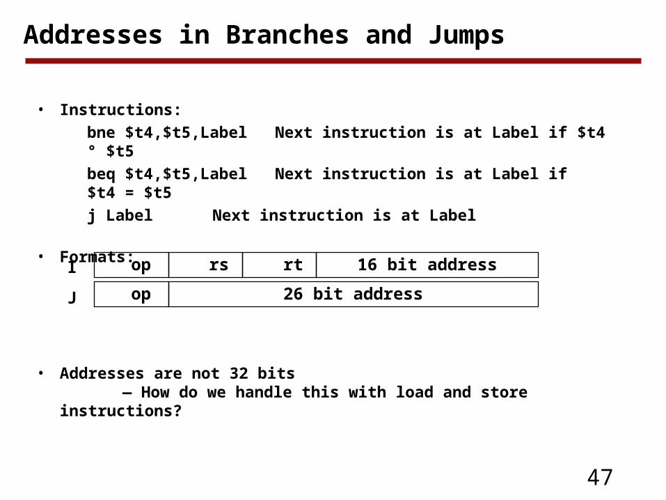
• Instructions:
bne $t4,$t5,Label Next instruction is at Label if $t4 ° $t5
beq $t4,$t5,Label Next instruction is at Label if $t4 = $t5
j Label Next instruction is at Label
• Formats:
• Addresses are not 32 bits — How do we handle this with load and store instructions?
op rs rt 16 bit address
op 26 bit address
I
J
Addresses in Branches and Jumps

48
• Instructions:
bne $t4,$t5,Label Next instruction is at Label if $t4≠$t5beq $t4,$t5,Label Next instruction is at Label if $t4=$t5
• Formats:
• Could specify a register (like lw and sw) and add it to address
– use Instruction Address Register (PC = program counter)
– most branches are local (principle of locality)
• Jump instructions just use high order bits of PC
– address boundaries of 256 MB
op rs rt 16 bit addressI
Addresses in Branches
49
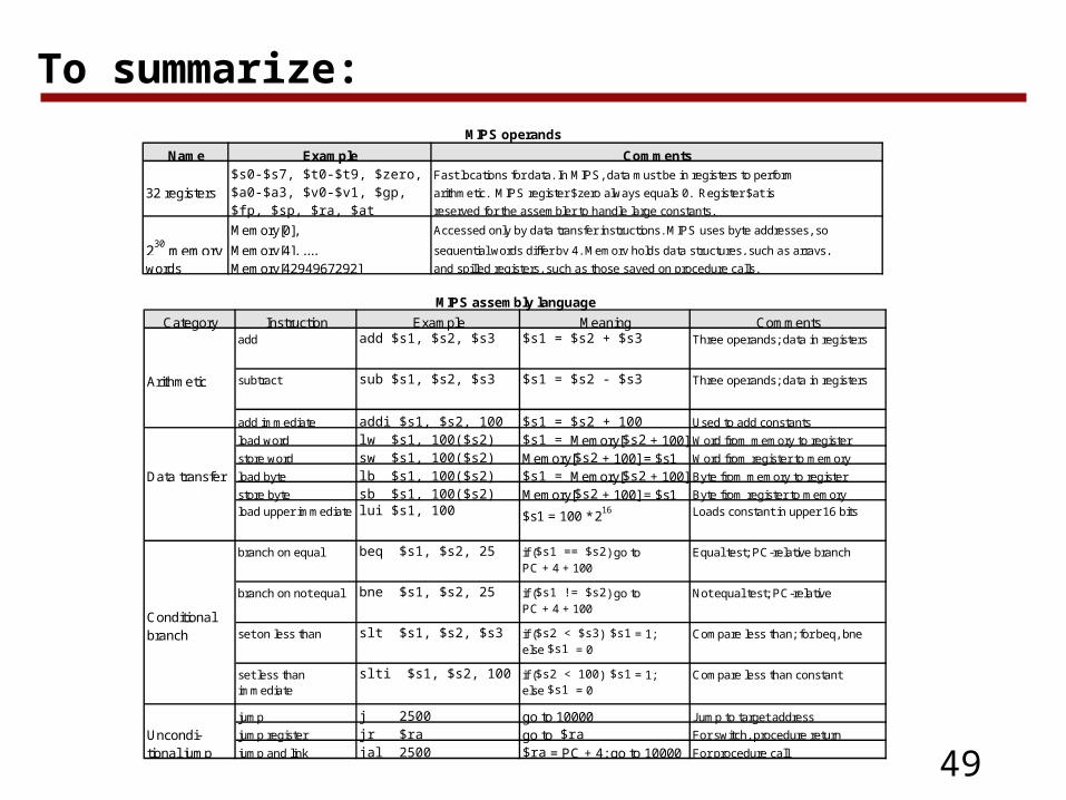
To summarize:MIPS operands
Name Example Comments$s0-$s7, $t0-$t9, $zero, Fast locations for data. In MIPS, data must be in registers to perform
32 registers $a0-$a3, $v0-$v1, $gp, arithmetic. MIPS register $zero always equals 0. Register $at is $fp, $sp, $ra, $at reserved for the assembler to handle large constants.
Memory[0], Accessed only by data transfer instructions. MIPS uses byte addresses, so
230
memory Memory[4], ..., sequential words differ by 4. Memory holds data structures, such as arrays,
words Memory[4294967292] and spilled registers, such as those saved on procedure calls.
MIPS assembly language
Category Instruction Example Meaning Commentsadd add $s1, $s2, $s3 $s1 = $s2 + $s3 Three operands; data in registers
Arithmetic subtract sub $s1, $s2, $s3 $s1 = $s2 - $s3 Three operands; data in registers
add immediate addi $s1, $s2, 100 $s1 = $s2 + 100 Used to add constants
load word lw $s1, 100($s2) $s1 = Memory[$s2 + 100] Word from memory to register
store word sw $s1, 100($s2) Memory[$s2 + 100] = $s1 Word from register to memory
Data transfer load byte lb $s1, 100($s2) $s1 = Memory[$s2 + 100] Byte from memory to register
store byte sb $s1, 100($s2) Memory[$s2 + 100] = $s1 Byte from register to memory
load upper immediate lui $s1, 100 $s1 = 100 * 216 Loads constant in upper 16 bits
branch on equal beq $s1, $s2, 25 if ($s1 == $s2) go to PC + 4 + 100
Equal test; PC-relative branch
Conditional
branch on not equal bne $s1, $s2, 25 if ($s1 != $s2) go to PC + 4 + 100
Not equal test; PC-relative
branch set on less than slt $s1, $s2, $s3 if ($s2 < $s3) $s1 = 1; else $s1 = 0
Compare less than; for beq, bne
set less than immediate
slti $s1, $s2, 100 if ($s2 < 100) $s1 = 1; else $s1 = 0
Compare less than constant
jump j 2500 go to 10000 Jump to target address
Uncondi- jump register jr $ra go to $ra For switch, procedure return
tional jump jump and link jal 2500 $ra = PC + 4; go to 10000 For procedure call

50
Byte Halfword Word
Registers
Memory
Memory
Word
Memory
Word
Register
Register
1. Immediate addressing
2. Register addressing
3. Base addressing
4. PC-relative addressing
5. Pseudodirect addressing
op rs rt
op rs rt
op rs rt
op
op
rs rt
Address
Address
Address
rd . . . funct
Immediate
PC
PC
+
+

51
• Design alternative:
– provide more powerful operations
– goal is to reduce number of instructions executed
– danger is a slower cycle time and/or a higher CPI
• Let’s look (briefly) at IA-32
Alternative Architectures
–“The path toward operation complexity is thus fraught with peril.
To avoid these problems, designers have moved toward simpler
instructions”

52
IA - 32
• 1978: The Intel 8086 is announced (16 bit architecture)• 1980: The 8087 floating point coprocessor is added• 1982: The 80286 increases address space to 24 bits, +instructions• 1985: The 80386 extends to 32 bits, new addressing modes• 1989-1995: The 80486, Pentium, Pentium Pro add a few instructions
(mostly designed for higher performance)• 1997: 57 new “MMX” instructions are added, Pentium II• 1999: The Pentium III added another 70 instructions (SSE)• 2001: Another 144 instructions (SSE2)• 2003: AMD extends the architecture to increase address space to 64 bits,
widens all registers to 64 bits and other changes (AMD64)• 2004: Intel capitulates and embraces AMD64 (calls it EM64T) and adds
more media extensions
• “This history illustrates the impact of the “golden handcuffs” of compatibility
“adding new features as someone might add clothing to a packed bag”
“an architecture that is difficult to explain and impossible to love”

53
IA-32 Overview
• Complexity:
– Instructions from 1 to 17 bytes long
– one operand must act as both a source and destination
– one operand can come from memory
– complex addressing modese.g., “base or scaled index with 8 or 32 bit
displacement”
• Saving grace:
– the most frequently used instructions are not too difficult to build
– compilers avoid the portions of the architecture that are slow
“what the 80x86 lacks in style is made up in quantity, making it beautiful from the right perspective”

54
IA-32 Registers and Data Addressing
• Registers in the 32-bit subset that originated with 80386
GPR 0
GPR 1
GPR 2
GPR 3
GPR 4
GPR 5
GPR 6
GPR 7
Code segment pointer
Stack segment pointer (top of stack)
Data segment pointer 0
Data segment pointer 1
Data segment pointer 2
Data segment pointer 3
Instruction pointer (PC)
Condition codes
Use
031Name
EAX
ECX
EDX
EBX
ESP
EBP
ESI
EDI
CS
SS
DS
ES
FS
GS
EIP
EFLAGS

55
IA-32 Register Restrictions
• Registers are not “general purpose” – note the restrictions below

56
IA-32 Typical Instructions
• Four major types of integer instructions:
– Data movement including move, push, pop
– Arithmetic and logical (destination register or memory)
– Control flow (use of condition codes / flags )
– String instructions, including string move and string compare

57
IA-32 instruction Formats
• Typical formats: (notice the different lengths)
a. JE EIP + displacement
b. CALL
c. MOV EBX, [EDI + 45]
d. PUSH ESI
e. ADD EAX, #6765
f. TEST EDX, #42
ImmediatePostbyteTEST
ADD
PUSH
MOV
CALL
JE
w
w ImmediateReg
Reg
wd Displacementr/m
Postbyte
Offset
DisplacementCondi-tion
4 4 8
8 32
6 81 1 8
5 3
4 323 1
7 321 8

58
• Instruction complexity is only one variable
– lower instruction count vs. higher CPI / lower clock rate
• Design Principles:
– simplicity favors regularity
– smaller is faster
– good design demands compromise
– make the common case fast
• Instruction set architecture
– a very important abstraction indeed!
Summary