Embed Size (px)
Citation preview

1
Chapter Seven
2
• SRAM:
– value is stored on a pair of inverting gates
– very fast but takes up more space than DRAM (4 to 6 transistors)
• DRAM:
– value is stored as a charge on capacitor (must be refreshed)
– very small but slower than SRAM (factor of 5 to 10)
Memories: Review
B
A A
B
Word line
Pass transistor
Capacitor
Bit line
3
• Users want large and fast memories!
SRAM access times are 2 - 25ns at cost of $100 to $250 per Mbyte.DRAM access times are 60-120ns at cost of $5 to $10 per Mbyte.Disk access times are 10 to 20 million ns at cost of $.10 to $.20 per Mbyte.
• Try and give it to them anyway
– build a memory hierarchy
Exploiting Memory Hierarchy
1997
CPU
Level n
Level 2
Level 1
Levels in thememory hierarchy
Increasing distance from the CPU in
access time
Size of the memory at each level
4
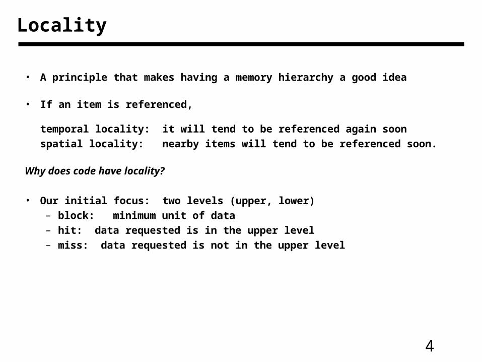
Locality
• A principle that makes having a memory hierarchy a good idea
• If an item is referenced,
temporal locality: it will tend to be referenced again soon
spatial locality: nearby items will tend to be referenced soon.
Why does code have locality?
• Our initial focus: two levels (upper, lower)– block: minimum unit of data – hit: data requested is in the upper level– miss: data requested is not in the upper level
5
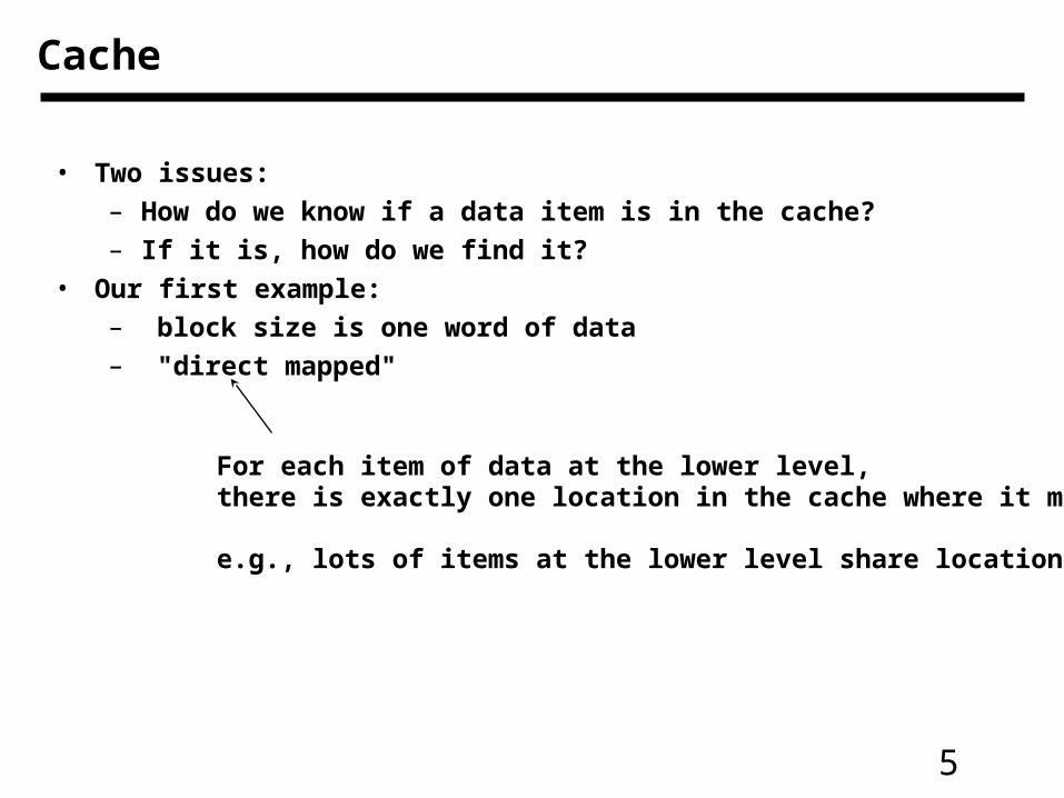
• Two issues:
– How do we know if a data item is in the cache?
– If it is, how do we find it?
• Our first example:
– block size is one word of data
– "direct mapped"
For each item of data at the lower level, there is exactly one location in the cache where it might be.
e.g., lots of items at the lower level share locations in the upper level
Cache

6
• Mapping: address is modulo the number of blocks in the cache
Direct Mapped Cache
00001 00101 01001 01101 10001 10101 11001 11101
000
Cache
Memory
001
01
001
11
001
011
101
11
7
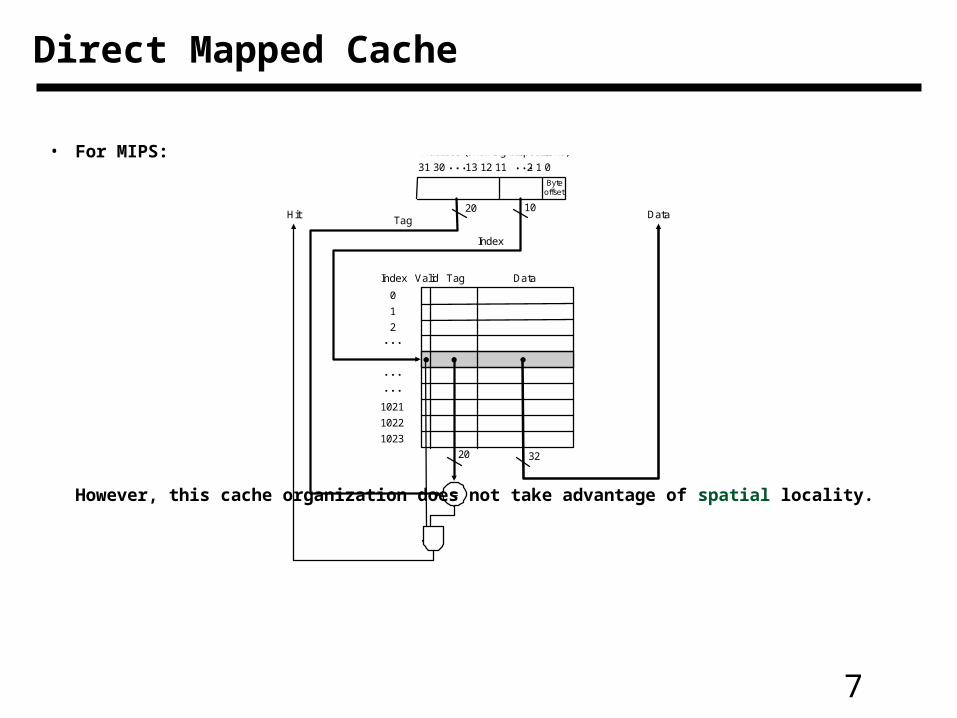
• For MIPS:
However, this cache organization does not take advantage of spatial locality.
Direct Mapped Cache
Address (showing bit positions)
20 10
Byteoffset
Valid Tag DataIndex
0
1
2
1021
1022
1023
Tag
Index
Hit Data
20 32
31 30 13 12 11 2 1 0
8
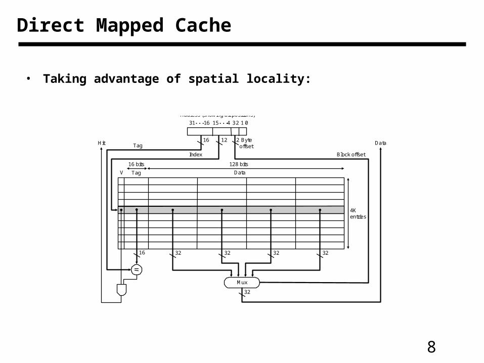
• Taking advantage of spatial locality:
Direct Mapped Cache
Address (showing bit positions)
16 12 Byteoffset
V Tag Data
Hit Data
16 32
4Kentries
16 bits 128 bits
Mux
32 32 32
2
32
Block offsetIndex
Tag
31 16 15 4 32 1 0
9
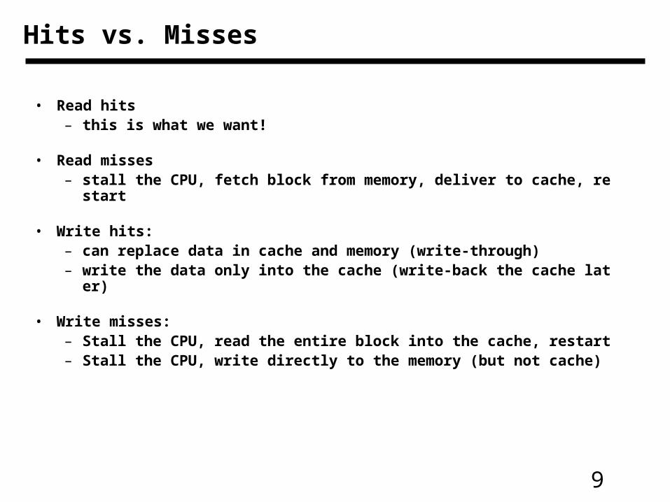
• Read hits– this is what we want!
• Read misses– stall the CPU, fetch block from memory, deliver to cache, restart
• Write hits:– can replace data in cache and memory (write-through)– write the data only into the cache (write-back the cache later)
• Write misses:– Stall the CPU, read the entire block into the cache, restart– Stall the CPU, write directly to the memory (but not cache)
Hits vs. Misses
10
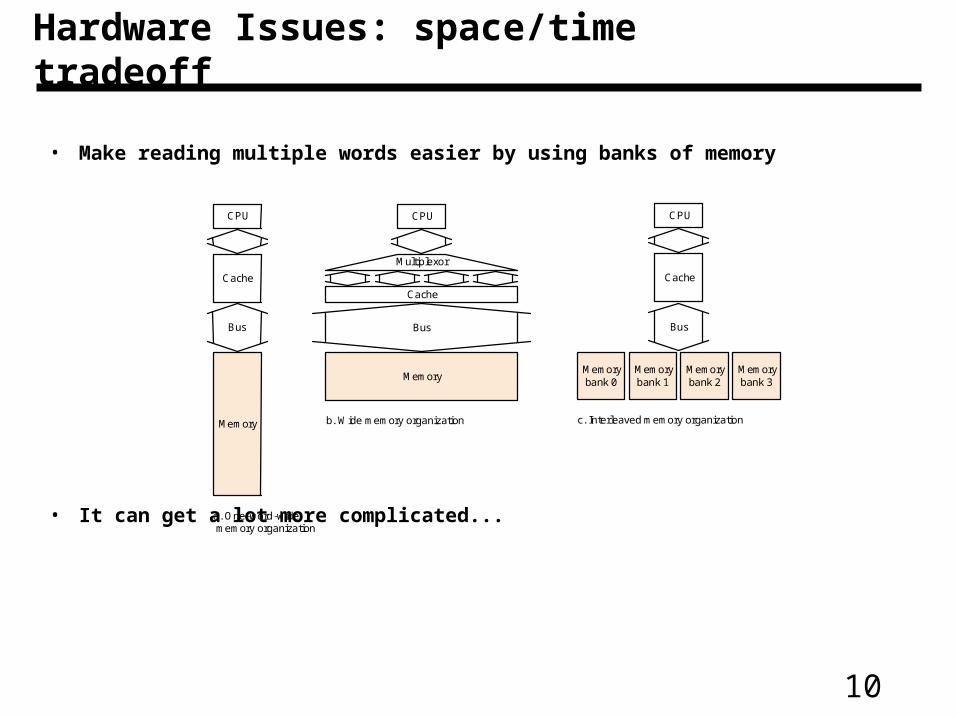
• Make reading multiple words easier by using banks of memory
• It can get a lot more complicated...
Hardware Issues: space/time tradeoff
CPU
Cache
Bus
Memory
a. One-word-wide memory organization
CPU
Bus
b. Wide memory organization
Memory
Multiplexor
Cache
CPU
Cache
Bus
Memorybank 1
Memorybank 2
Memorybank 3
Memorybank 0
c. Interleaved memory organization
11
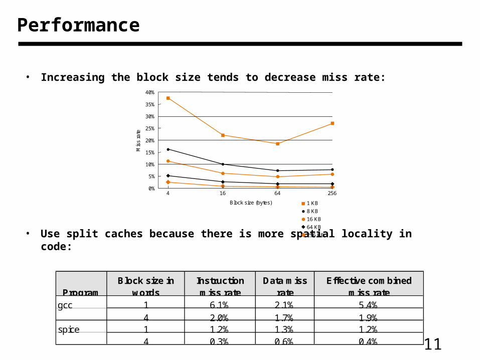
• Increasing the block size tends to decrease miss rate:
• Use split caches because there is more spatial locality in code:
Performance
1 KB
8 KB
16 KB
64 KB
256 KB
256
40%
35%
30%
25%
20%
15%
10%
5%
0%
Mis
s ra
te
64164
Block size (bytes)
ProgramBlock size in
wordsInstruction miss rate
Data miss rate
Effective combined miss rate
gcc 1 6.1% 2.1% 5.4%4 2.0% 1.7% 1.9%
spice 1 1.2% 1.3% 1.2%4 0.3% 0.6% 0.4%
12
Performance
• Simplified model:
execution time = (execution cycles + stall cycles) * cycle time
stall cycles = # of instructions * miss ratio * miss penalty
• Two ways of improving performance:
– decreasing the miss ratio
– decreasing the miss penalty
What happens if we increase block size?
13
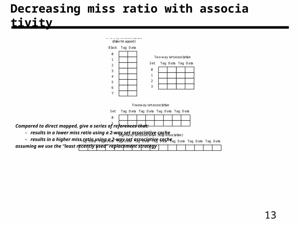
Compared to direct mapped, give a series of references that:
– results in a lower miss ratio using a 2-way set associative cache
– results in a higher miss ratio using a 2-way set associative cache
assuming we use the “least recently used” replacement strategy
Decreasing miss ratio with associativity
Tag Data Tag Data Tag Data Tag Data Tag Data Tag Data Tag Data Tag Data
Eight-way set associative (fully associative)
Tag Data Tag Data Tag Data Tag Data
Four-way set associative
Set
0
1
Tag Data
One-way set associative(direct mapped)
Block
0
7
1
2
3
4
5
6
Tag Data
Two-way set associative
Set
0
1
2
3
Tag Data
14
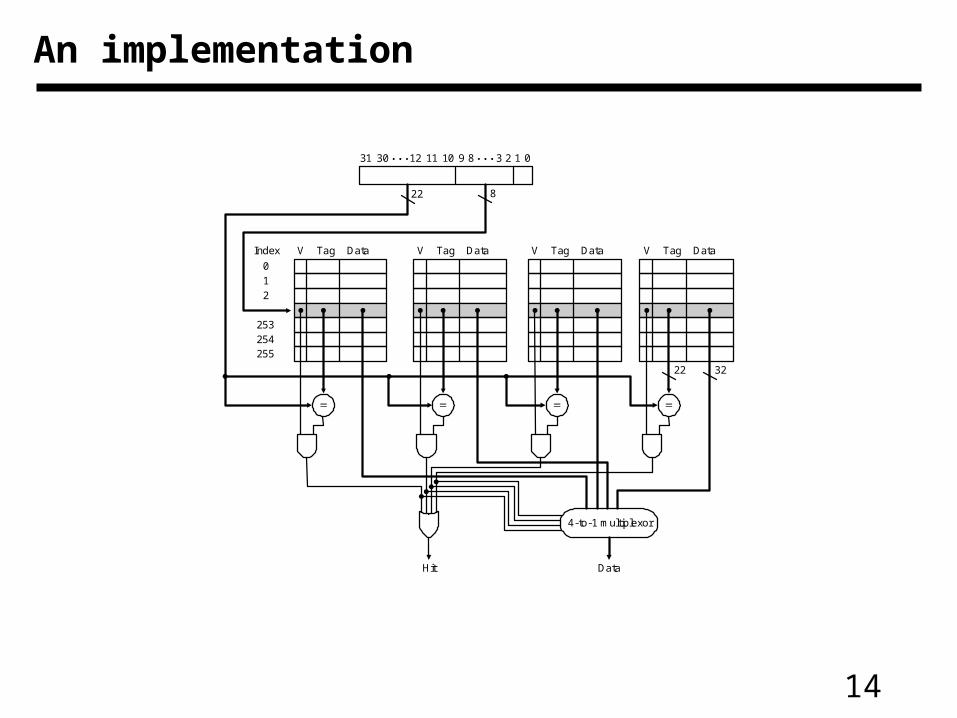
An implementation
Address
22 8
V TagIndex
01
2
253254255
Data V Tag Data V Tag Data V Tag Data
3222
4-to-1 multiplexor
Hit Data
123891011123031 0
15
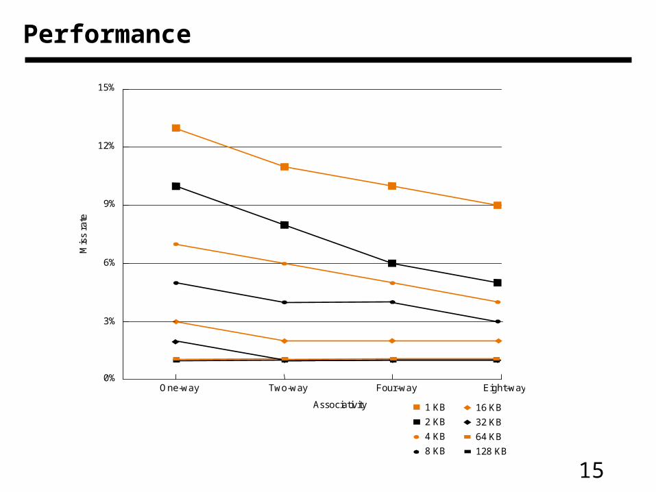
Performance
0%
3%
6%
9%
12%
15%
Eight-wayFour-wayTwo-wayOne-way
1 KB
2 KB
4 KB
8 KB
Mis
s ra
te
Associativity 16 KB
32 KB
64 KB
128 KB
16
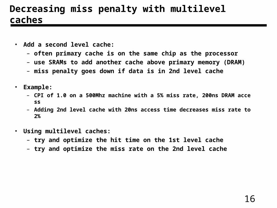
Decreasing miss penalty with multilevel caches
• Add a second level cache:
– often primary cache is on the same chip as the processor
– use SRAMs to add another cache above primary memory (DRAM)
– miss penalty goes down if data is in 2nd level cache
• Example:– CPI of 1.0 on a 500Mhz machine with a 5% miss rate, 200ns DRAM access– Adding 2nd level cache with 20ns access time decreases miss rate to 2%
• Using multilevel caches:
– try and optimize the hit time on the 1st level cache
– try and optimize the miss rate on the 2nd level cache
17
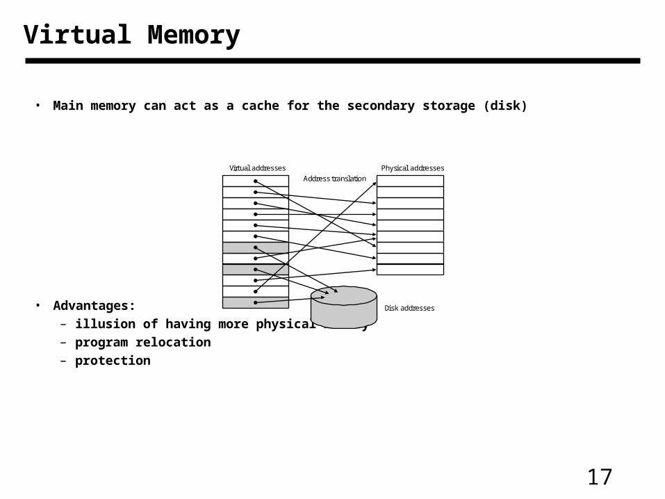
Virtual Memory
• Main memory can act as a cache for the secondary storage (disk)
• Advantages:– illusion of having more physical memory– program relocation – protection
Physical addresses
Disk addresses
Virtual addresses
Address translation
18
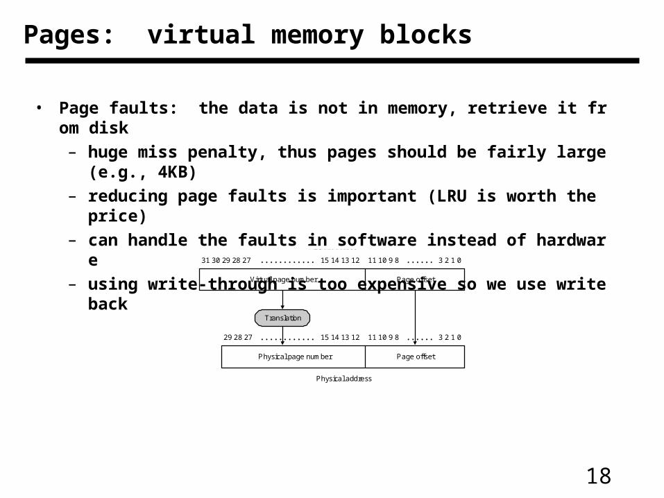
Pages: virtual memory blocks
• Page faults: the data is not in memory, retrieve it from disk
– huge miss penalty, thus pages should be fairly large (e.g., 4KB)
– reducing page faults is important (LRU is worth the price)
– can handle the faults in software instead of hardware
– using write-through is too expensive so we use writeback
3 2 1 011 10 9 815 14 13 1231 30 29 28 27
Page offsetVirtual page number
Virtual address
3 2 1 011 10 9 815 14 13 1229 28 27
Page offsetPhysical page number
Physical address
Translation
19
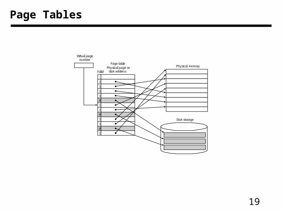
Page Tables
Physical memory
Disk storage
Valid
1
1
1
1
0
1
1
0
1
1
0
1
Page table
Virtual pagenumber
Physical page ordisk address
20
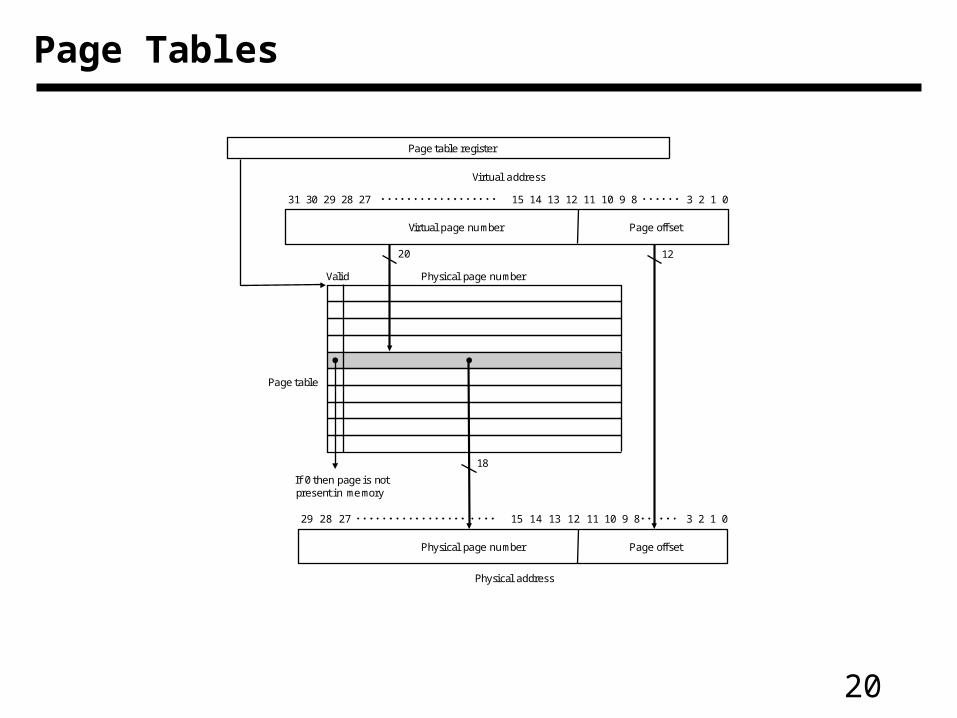
Page Tables
Page offsetVirtual page number
Virtual address
Page offsetPhysical page number
Physical address
Physical page numberValid
If 0 then page is notpresent in memory
Page table register
Page table
20 12
18
31 30 29 28 27 15 14 13 12 11 10 9 8 3 2 1 0
29 28 27 15 14 13 12 11 10 9 8 3 2 1 0
21
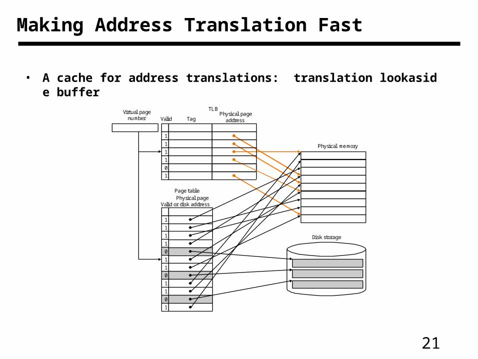
Making Address Translation Fast
• A cache for address translations: translation lookaside buffer
Valid
1
1
1
1
0
1
1
0
1
1
0
1
Page table
Physical pageaddressValid
TLB
1
1
1
1
0
1
TagVirtual page
number
Physical pageor disk address
Physical memory
Disk storage
22
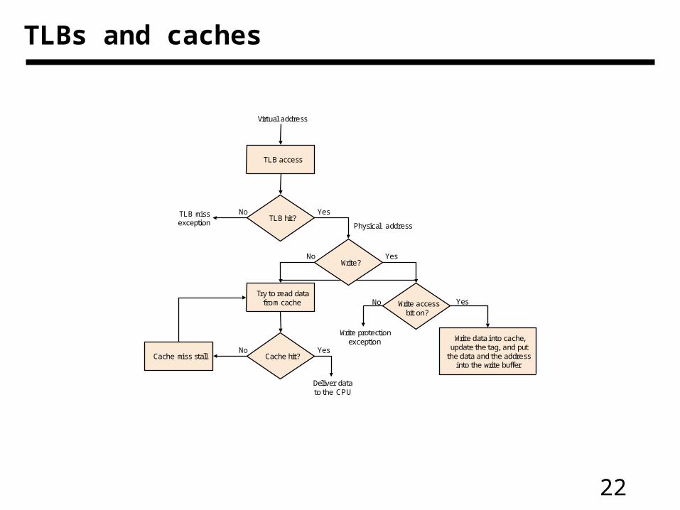
TLBs and caches
Yes
Deliver datato the CPU
Write?
Try to read datafrom cache
Write data into cache,update the tag, and put
the data and the addressinto the write buffer
Cache hit?Cache miss stall
TLB hit?
TLB access
Virtual address
TLB missexception
No
YesNo
YesNo
Write accessbit on?
YesNo
Write protectionexception
Physical address
23
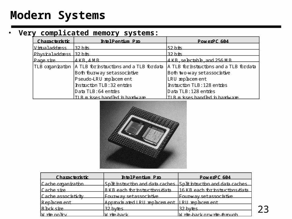
Modern Systems
• Very complicated memory systems:Characteristic Intel Pentium Pro PowerPC 604
Virtual address 32 bits 52 bitsPhysical address 32 bits 32 bitsPage size 4 KB, 4 MB 4 KB, selectable, and 256 MBTLB organization A TLB for instructions and a TLB for data A TLB for instructions and a TLB for data
Both four-way set associative Both two-way set associativePseudo-LRU replacement LRU replacementInstruction TLB: 32 entries Instruction TLB: 128 entriesData TLB: 64 entries Data TLB: 128 entriesTLB misses handled in hardware TLB misses handled in hardware
Characteristic Intel Pentium Pro PowerPC 604Cache organization Split instruction and data caches Split intruction and data cachesCache size 8 KB each for instructions/data 16 KB each for instructions/dataCache associativity Four-way set associative Four-way set associativeReplacement Approximated LRU replacement LRU replacementBlock size 32 bytes 32 bytesWrite policy Write-back Write-back or write-through
24
• Processor speeds continue to increase very fast— much faster than either DRAM or disk access times
• Design challenge: dealing with this growing disparity
• Trends:
– synchronous SRAMs (provide a burst of data)
– redesign DRAM chips to provide higher bandwidth or processing
– restructure code to increase locality
– use prefetching (make cache visible to ISA)
Some Issues
25
Chapters 8 & 9
(partial coverage)
26
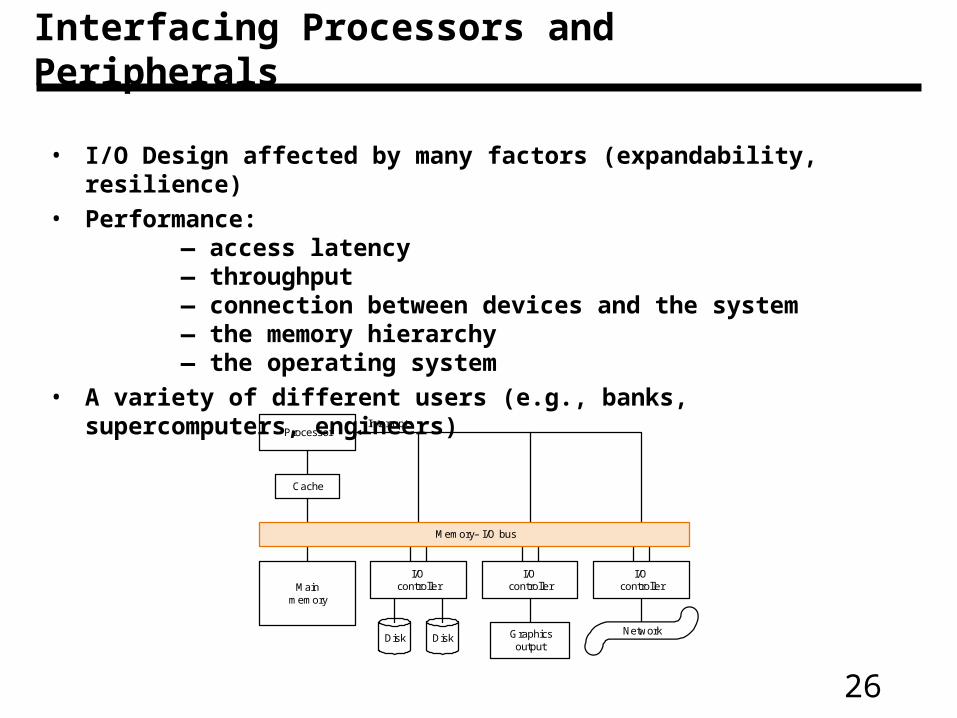
Interfacing Processors and Peripherals
• I/O Design affected by many factors (expandability, resilience)
• Performance:— access latency — throughput— connection between devices and the system— the memory hierarchy— the operating system
• A variety of different users (e.g., banks, supercomputers, engineers)
Mainmemory
I/Ocontroller
I/Ocontroller
I/Ocontroller
Disk Graphicsoutput
Network
Memory– I/O bus
Processor
Cache
Interrupts
Disk
27
I/O
• Important but neglected
“The difficulties in assessing and designing I/O systems haveoften relegated I/O to second class status”
“courses in every aspect of computing, from programming tocomputer architecture often ignore I/O or give it scanty coverage”
“textbooks leave the subject to near the end, making it easierfor students and instructors to skip it!”
• GUILTY!
— we won’t be looking at I/O in much detail
— be sure and read Chapter 8 in its entirety.
— you should probably take a networking class!
28
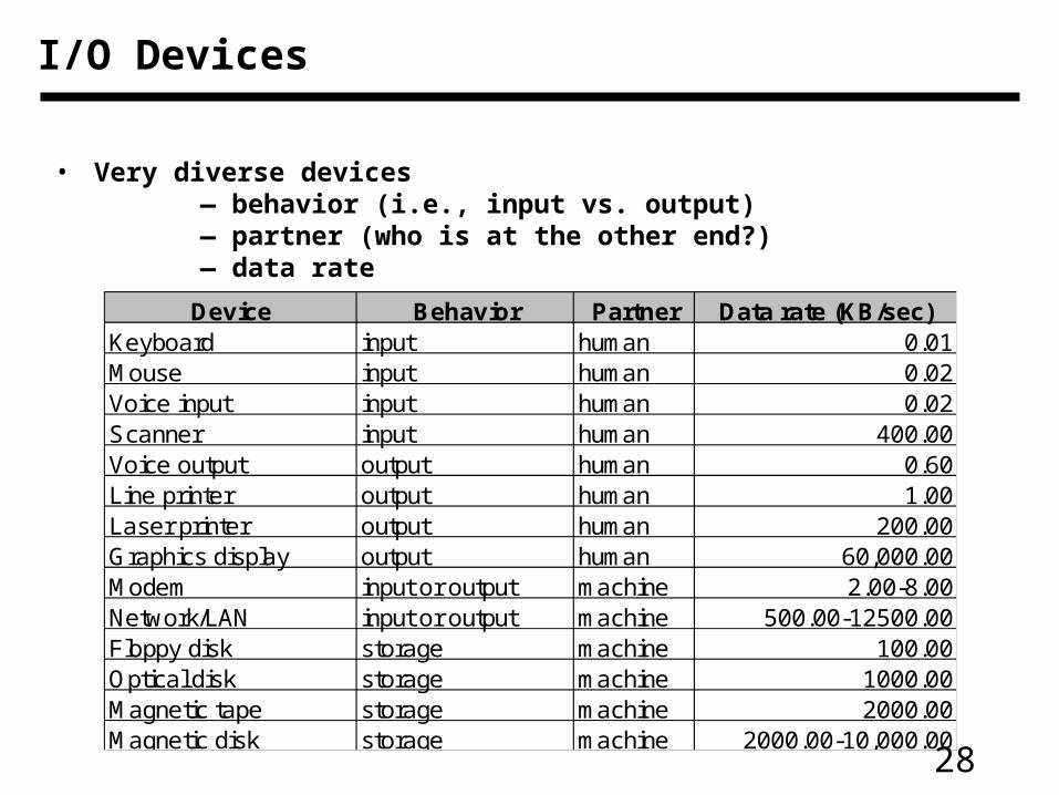
I/O Devices
• Very diverse devices— behavior (i.e., input vs. output)— partner (who is at the other end?)— data rate
Device Behavior Partner Data rate (KB/sec)Keyboard input human 0.01Mouse input human 0.02Voice input input human 0.02Scanner input human 400.00Voice output output human 0.60Line printer output human 1.00Laser printer output human 200.00Graphics display output human 60,000.00Modem input or output machine 2.00-8.00Network/LAN input or output machine 500.00-12500.00Floppy disk storage machine 100.00Optical disk storage machine 1000.00Magnetic tape storage machine 2000.00Magnetic disk storage machine 2000.00-10,000.00
29
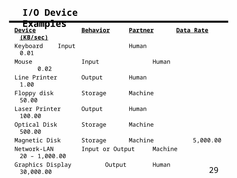
I/O Device Examples
Device Behavior Partner Data Rate (KB/sec)
Keyboard Input Human 0.01
Mouse Input Human 0.02
Line Printer Output Human 1.00
Floppy disk Storage Machine 50.00
Laser Printer Output Human 100.00
Optical Disk Storage Machine 500.00
Magnetic Disk Storage Machine 5,000.00
Network-LAN Input or Output Machine 20 – 1,000.00
Graphics Display Output Human 30,000.00
30
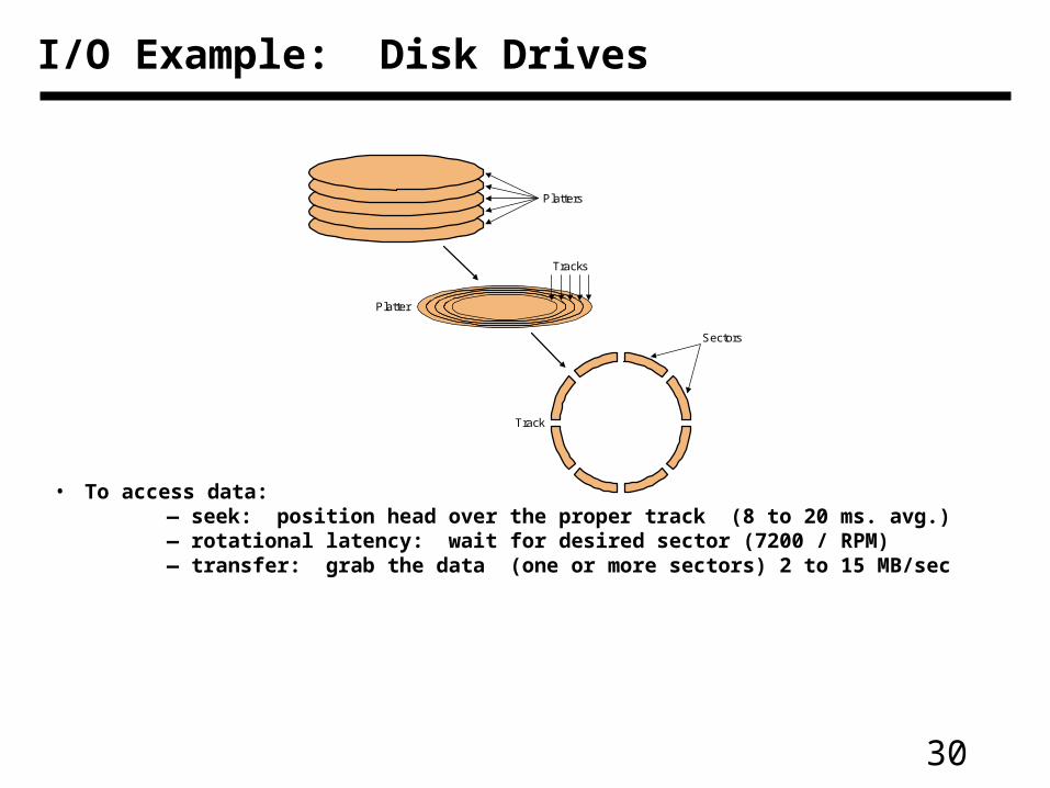
I/O Example: Disk Drives
• To access data:— seek: position head over the proper track (8 to 20 ms. avg.)— rotational latency: wait for desired sector (7200 / RPM)— transfer: grab the data (one or more sectors) 2 to 15 MB/sec
Platter
Track
Platters
Sectors
Tracks
31
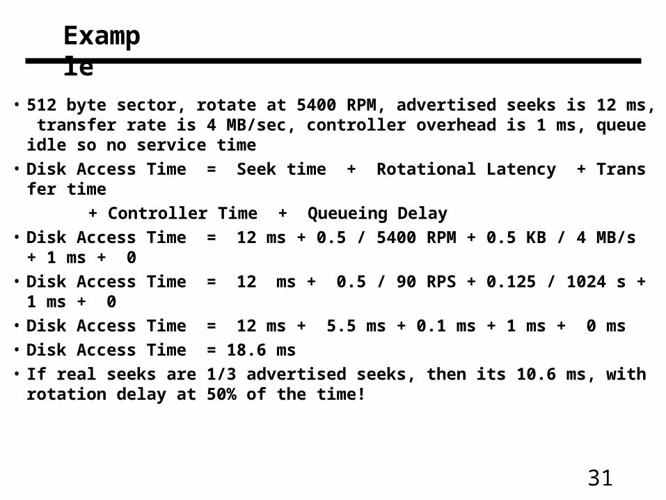
Example
• 512 byte sector, rotate at 5400 RPM, advertised seeks is 12 ms, transfer rate is 4 MB/sec, controller overhead is 1 ms, queue idle so no service time
• Disk Access Time = Seek time + Rotational Latency + Transfer time
+ Controller Time + Queueing Delay
• Disk Access Time = 12 ms + 0.5 / 5400 RPM + 0.5 KB / 4 MB/s + 1 ms + 0
• Disk Access Time = 12 ms + 0.5 / 90 RPS + 0.125 / 1024 s + 1 ms + 0
• Disk Access Time = 12 ms + 5.5 ms + 0.1 ms + 1 ms + 0 ms
• Disk Access Time = 18.6 ms
• If real seeks are 1/3 advertised seeks, then its 10.6 ms, with rotation delay at 50% of the time!
32
I/O Example: Buses
• Shared communication link (one or more wires)• Difficult design:
— may be bottleneck— length of the bus— number of devices— tradeoffs (buffers for higher bandwidth increases latency)— support for many different devices— cost
• Types of buses:— processor-memory (short high speed, custom design)— backplane (high speed, often standardized, e.g., PCI)— I/O (lengthy, different devices, standardized, e.g., SCSI)
• Synchronous vs. Asynchronous— use a clock and a synchronous protocol, fast and small
but every device must operate at same rate andclock skew requires the bus to be short
— don’t use a clock and instead use handshaking
33
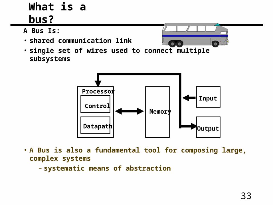
A Bus Is:
• shared communication link
• single set of wires used to connect multiple subsystems
• A Bus is also a fundamental tool for composing large, complex systems
– systematic means of abstraction
Control
Datapath
Memory
ProcessorInput
Output
What is a bus?
34
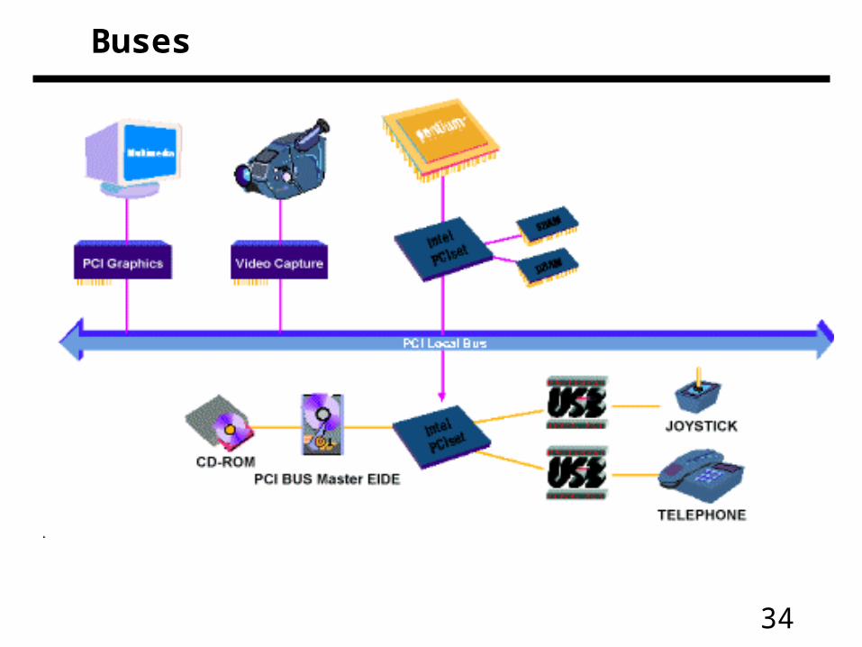
Buses
35
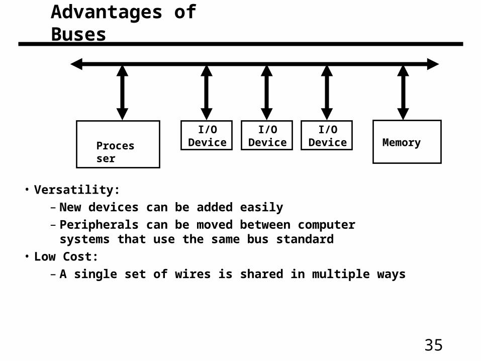
• Versatility:
– New devices can be added easily
– Peripherals can be moved between computersystems that use the same bus standard
• Low Cost:
– A single set of wires is shared in multiple ways
MemoryProcesser
I/O Device
I/O Device
I/O Device
Advantages of Buses
36
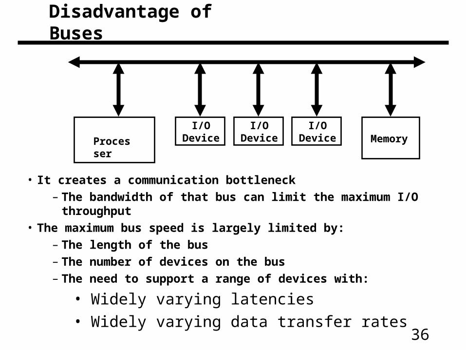
• It creates a communication bottleneck
– The bandwidth of that bus can limit the maximum I/O throughput
• The maximum bus speed is largely limited by:
– The length of the bus
– The number of devices on the bus
– The need to support a range of devices with:
• Widely varying latencies
• Widely varying data transfer rates
MemoryProcesser
I/O Device
I/O Device
I/O Device
Disadvantage of Buses
37
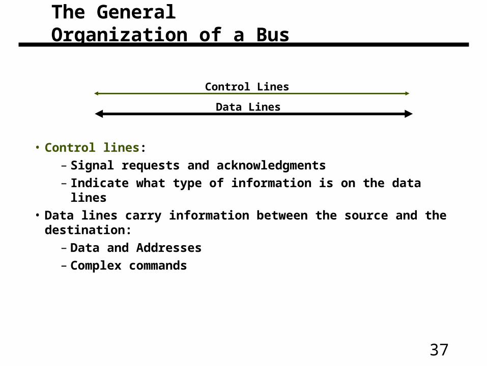
• Control lines:
– Signal requests and acknowledgments
– Indicate what type of information is on the data lines
• Data lines carry information between the source and the destination:
– Data and Addresses
– Complex commands
Data Lines
Control Lines
The General Organization of a Bus
38
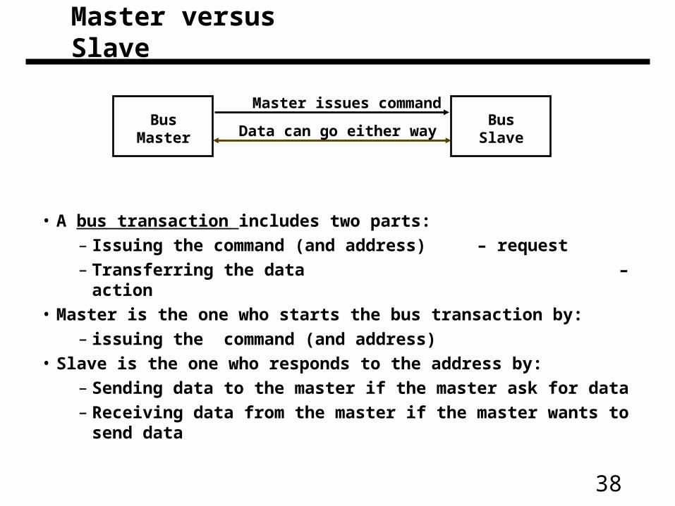
• A bus transaction includes two parts:
– Issuing the command (and address) – request
– Transferring the data – action
• Master is the one who starts the bus transaction by:
– issuing the command (and address)
• Slave is the one who responds to the address by:
– Sending data to the master if the master ask for data
– Receiving data from the master if the master wants to send data
BusMaster
BusSlave
Master issues command
Data can go either way
Master versus Slave
39
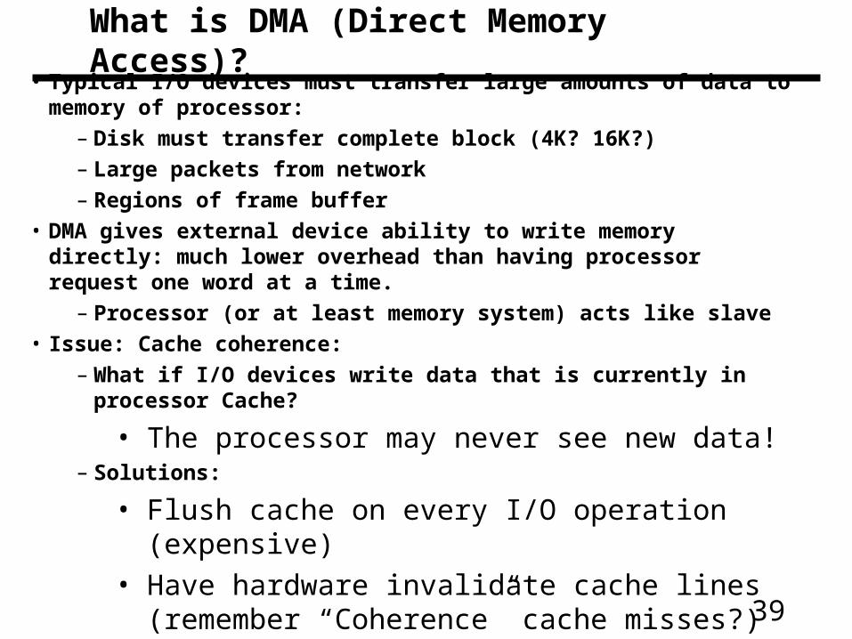
What is DMA (Direct Memory Access)?
• Typical I/O devices must transfer large amounts of data to memory of processor:
– Disk must transfer complete block (4K? 16K?)
– Large packets from network
– Regions of frame buffer
• DMA gives external device ability to write memory directly: much lower overhead than having processor request one word at a time.
– Processor (or at least memory system) acts like slave
• Issue: Cache coherence:
– What if I/O devices write data that is currently in processor Cache?
• The processor may never see new data!– Solutions:
• Flush cache on every I/O operation (expensive)
• Have hardware invalidate cache lines (remember “Coherence” cache misses?)
40
Types of Buses• Processor-Memory Bus (design specific)
– Short and high speed
– Only need to match the memory system
• Maximize memory-to-processor bandwidth– Connects directly to the processor
– Optimized for cache block transfers
• I/O Bus (industry standard)
– Usually is lengthy and slower
– Need to match a wide range of I/O devices
– Connects to the processor-memory bus or backplane bus
• Backplane Bus (standard or proprietary)
– Backplane: an interconnection structure within the chassis
– Allow processors, memory, and I/O devices to coexist
– Cost advantage: one bus for all components
41
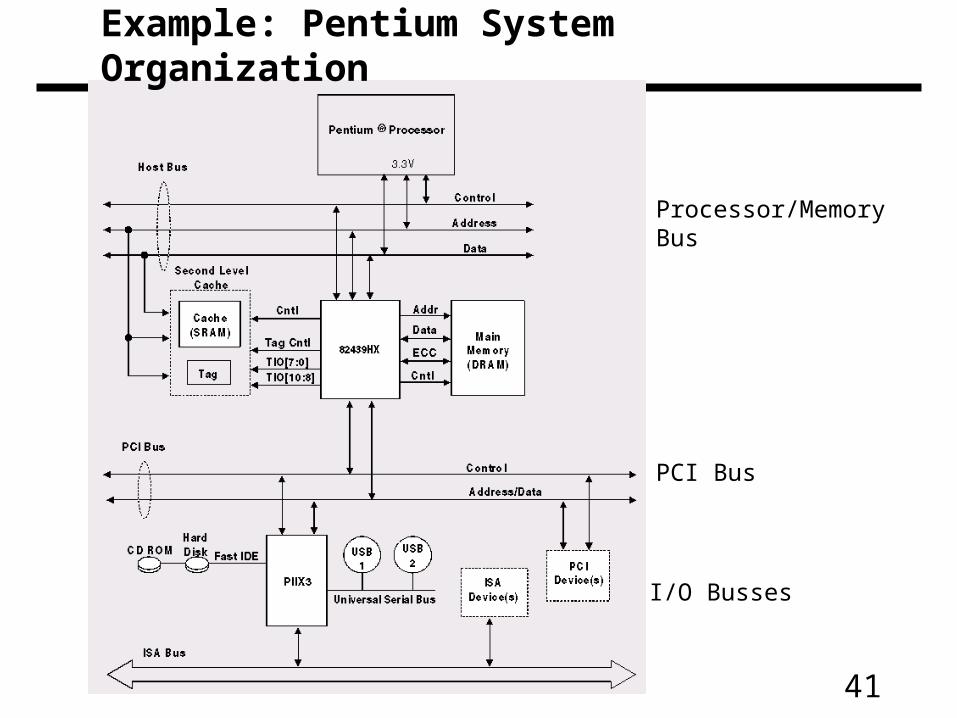
Processor/MemoryBus
PCI Bus
I/O Busses
Example: Pentium System Organization

42
A Computer System with One Bus: Backplane Bus
• A single bus (the backplane bus) is used for:
– Processor to memory communication
– Communication between I/O devices and memory
• Advantages: Simple and low cost
• Disadvantages: slow and the bus can become a major bottleneck
• Example: IBM PC - AT
Processor Memory
I/O Devices
Backplane Bus
43
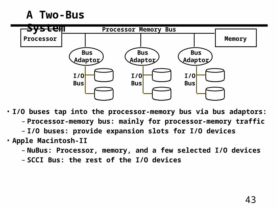
A Two-Bus System
• I/O buses tap into the processor-memory bus via bus adaptors:– Processor-memory bus: mainly for processor-memory traffic– I/O buses: provide expansion slots for I/O devices
• Apple Macintosh-II– NuBus: Processor, memory, and a few selected I/O devices– SCCI Bus: the rest of the I/O devices
Processor Memory
I/OBus
Processor Memory Bus
BusAdaptor
BusAdaptor
BusAdaptor
I/OBus
I/OBus
44
A Three-Bus System (+ backside cache)
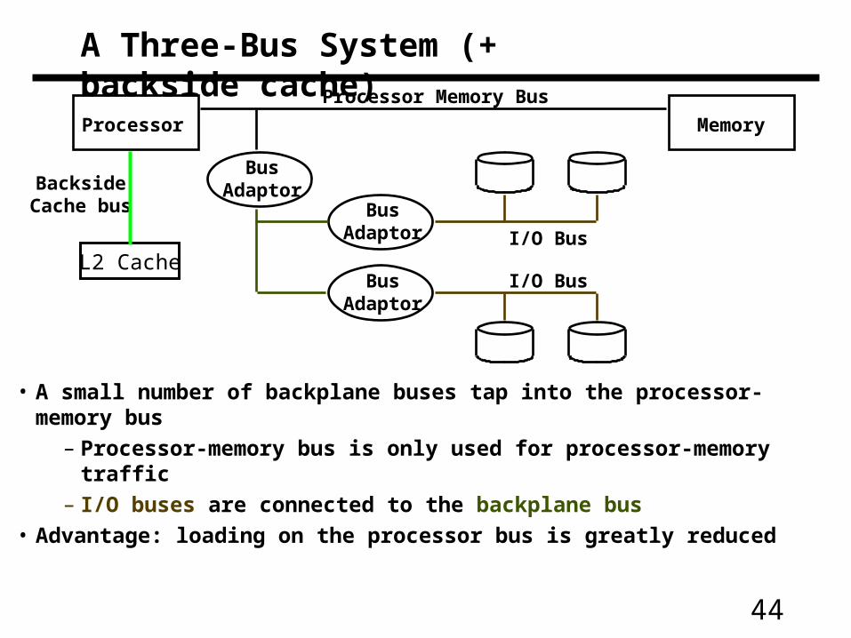
• A small number of backplane buses tap into the processor-memory bus
– Processor-memory bus is only used for processor-memory traffic
– I/O buses are connected to the backplane bus
• Advantage: loading on the processor bus is greatly reduced
Processor Memory
Processor Memory Bus
BusAdaptor
BusAdaptor
BusAdaptor
I/O Bus
BacksideCache bus
I/O BusL2 Cache
45
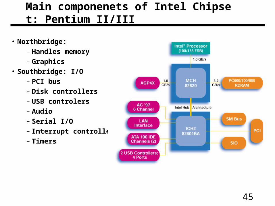
Main componenets of Intel Chipset: Pentium II/III
• Northbridge:
– Handles memory
– Graphics
• Southbridge: I/O
– PCI bus
– Disk controllers
– USB controlers
– Audio
– Serial I/O
– Interrupt controller
– Timers
46
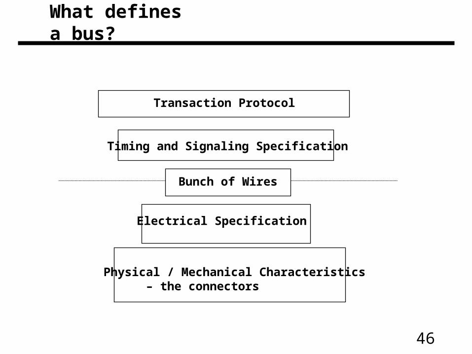
Bunch of Wires
Physical / Mechanical Characteristics – the connectors
Electrical Specification
Timing and Signaling Specification
Transaction Protocol
What defines a bus?
47
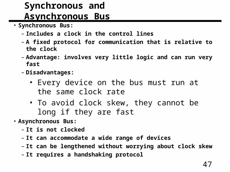
• Synchronous Bus:
– Includes a clock in the control lines
– A fixed protocol for communication that is relative to the clock
– Advantage: involves very little logic and can run very fast
– Disadvantages:
• Every device on the bus must run at the same clock rate
• To avoid clock skew, they cannot be long if they are fast• Asynchronous Bus:
– It is not clocked
– It can accommodate a wide range of devices
– It can be lengthened without worrying about clock skew
– It requires a handshaking protocol
Synchronous and Asynchronous Bus
48
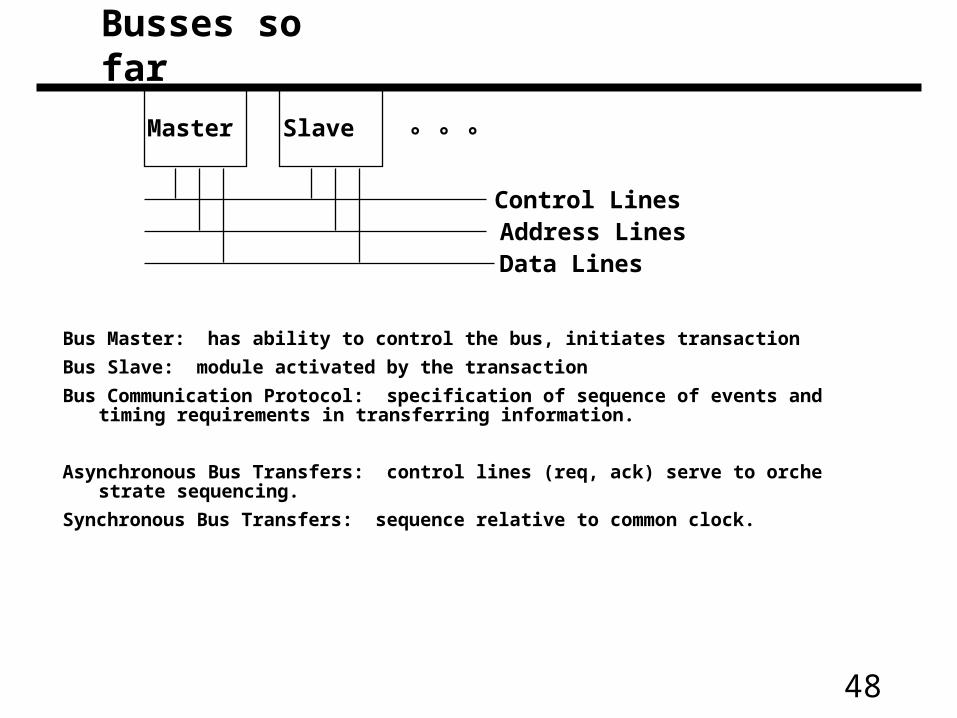
° ° °Master Slave
Control LinesAddress LinesData Lines
Bus Master: has ability to control the bus, initiates transaction
Bus Slave: module activated by the transaction
Bus Communication Protocol: specification of sequence of events and timing requirements in transferring information.
Asynchronous Bus Transfers: control lines (req, ack) serve to orchestrate sequencing.
Synchronous Bus Transfers: sequence relative to common clock.
Busses so far
49
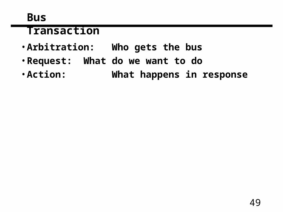
Bus Transaction
• Arbitration: Who gets the bus• Request: What do we want to do• Action: What happens in response
50
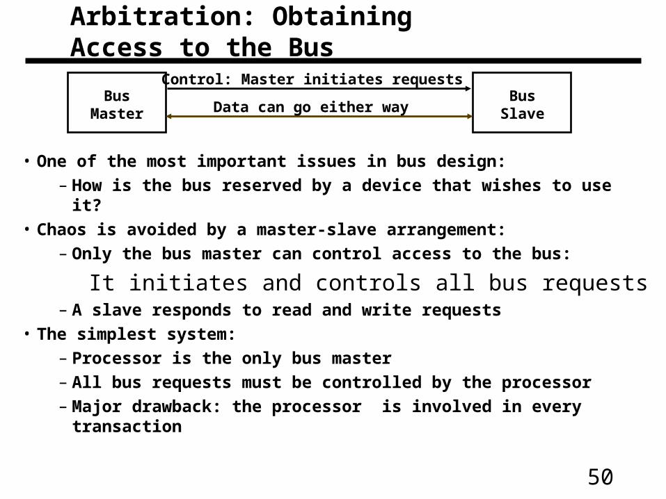
• One of the most important issues in bus design:
– How is the bus reserved by a device that wishes to use it?
• Chaos is avoided by a master-slave arrangement:
– Only the bus master can control access to the bus:
It initiates and controls all bus requests– A slave responds to read and write requests
• The simplest system:
– Processor is the only bus master
– All bus requests must be controlled by the processor
– Major drawback: the processor is involved in every transaction
BusMaster
BusSlave
Control: Master initiates requests
Data can go either way
Arbitration: Obtaining Access to the Bus
51
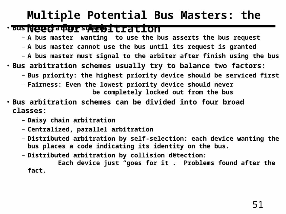
Multiple Potential Bus Masters: the Need for Arbitration• Bus arbitration scheme:
– A bus master wanting to use the bus asserts the bus request– A bus master cannot use the bus until its request is granted– A bus master must signal to the arbiter after finish using the bus
• Bus arbitration schemes usually try to balance two factors:– Bus priority: the highest priority device should be serviced first– Fairness: Even the lowest priority device should never
be completely locked out from the bus
• Bus arbitration schemes can be divided into four broad classes:– Daisy chain arbitration– Centralized, parallel arbitration– Distributed arbitration by self-selection: each device wanting the bus places a code
indicating its identity on the bus.– Distributed arbitration by collision detection:
Each device just “goes for it”. Problems found after the fact.
52
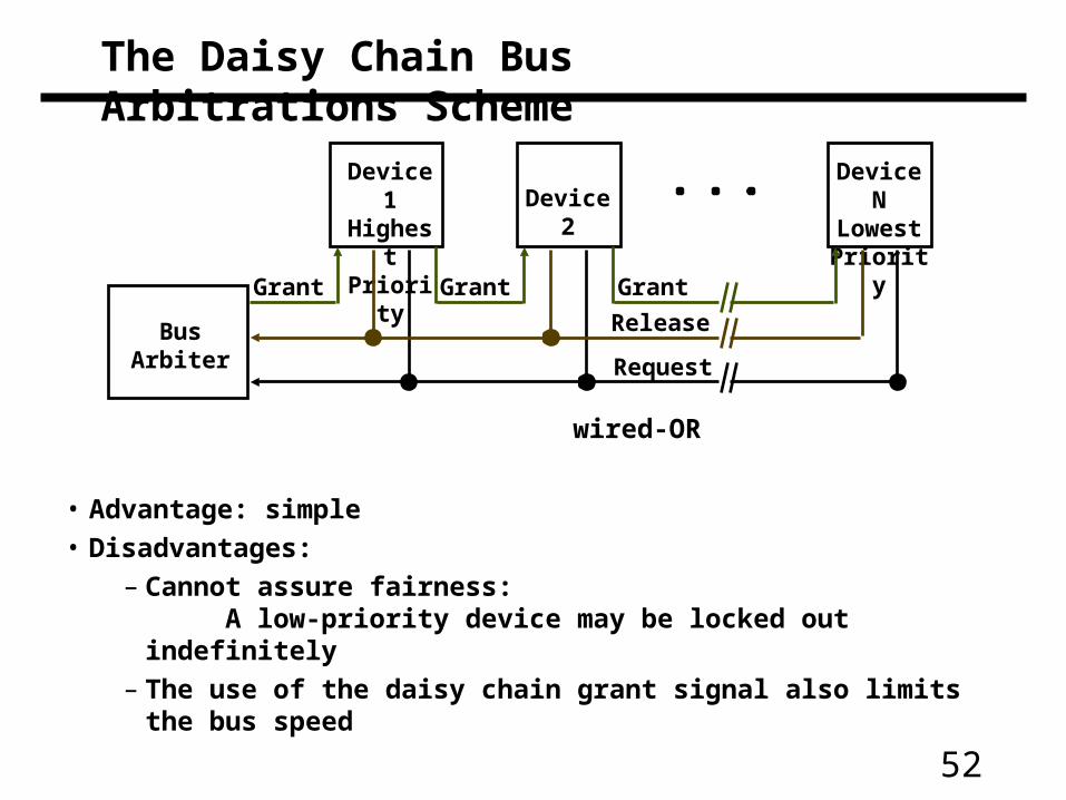
The Daisy Chain Bus Arbitrations Scheme
• Advantage: simple
• Disadvantages:
– Cannot assure fairness: A low-priority device may be locked out indefinitely
– The use of the daisy chain grant signal also limits the bus speed
BusArbiter
Device 1HighestPriority
Device NLowestPriority
Device 2
Grant Grant Grant
Release
Request
wired-OR
53
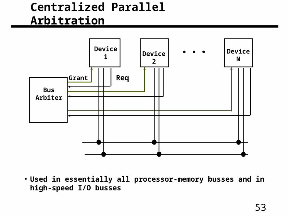
• Used in essentially all processor-memory busses and in high-speed I/O busses
BusArbiter
Device 1 Device NDevice 2
Grant Req
Centralized Parallel Arbitration
54
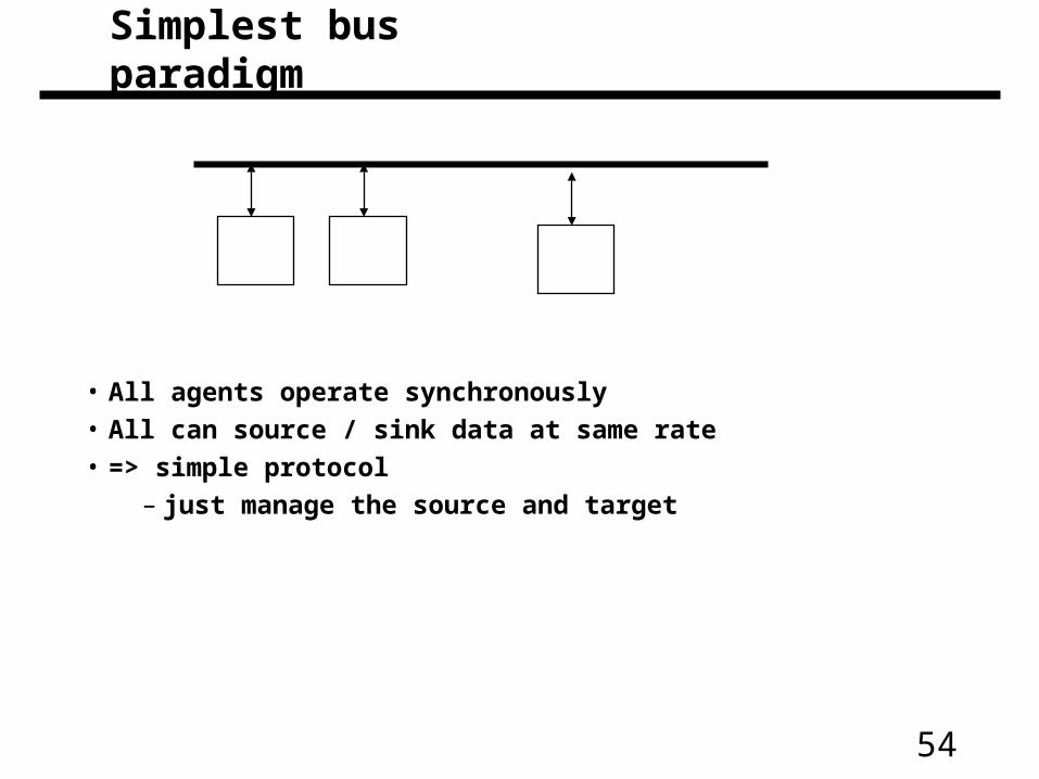
• All agents operate synchronously
• All can source / sink data at same rate
• => simple protocol
– just manage the source and target
Simplest bus paradigm
55
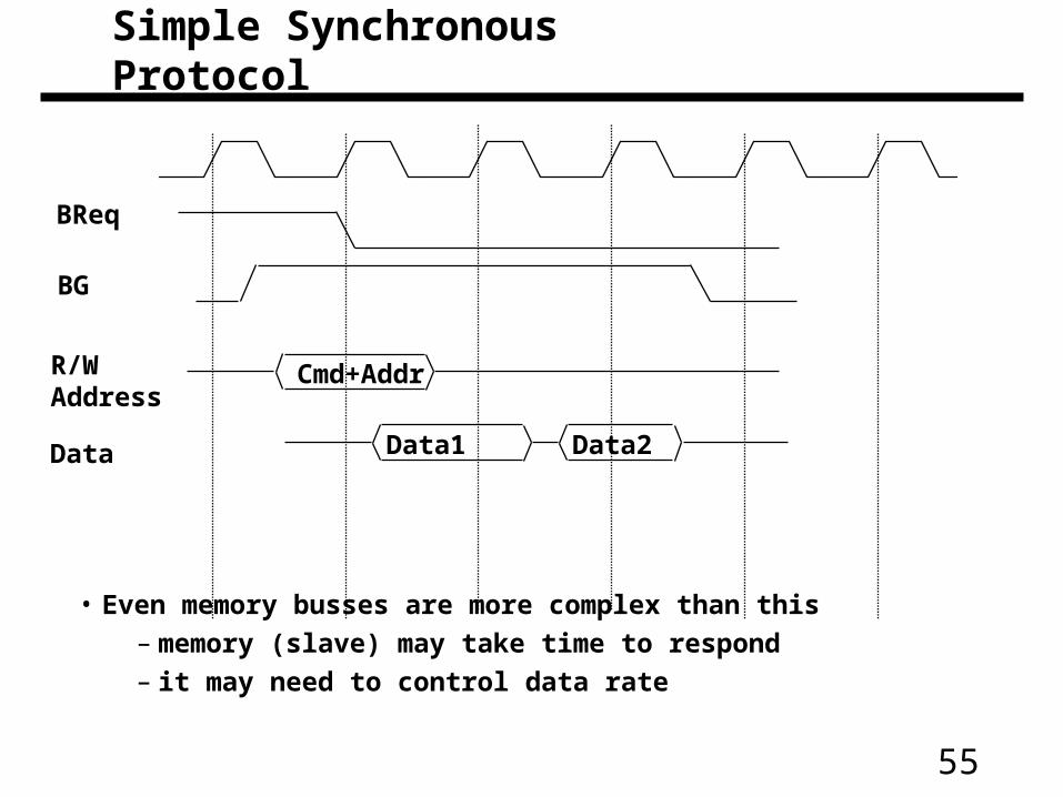
• Even memory busses are more complex than this
– memory (slave) may take time to respond
– it may need to control data rate
BReq
BG
Cmd+AddrR/WAddress
Data1 Data2Data
Simple Synchronous Protocol
56
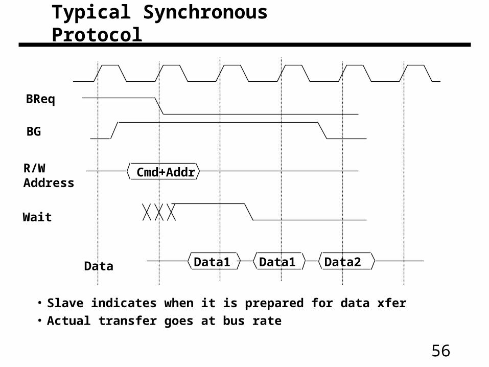
• Slave indicates when it is prepared for data xfer
• Actual transfer goes at bus rate
BReq
BG
Cmd+AddrR/WAddress
Data1 Data2Data Data1
Wait
Typical Synchronous Protocol
57
• Separate versus multiplexed address and data lines:– Address and data can be transmitted in one bus cycle
if separate address and data lines are available– Cost: (a) more bus lines, (b) increased complexity
• Data bus width:– By increasing the width of the data bus, transfers of multiple words require
fewer bus cycles– Example: SPARCstation 20’s memory bus is 128 bit wide– Cost: more bus lines
• Block transfers:– Allow the bus to transfer multiple words in back-to-back bus cycles– Only one address needs to be sent at the beginning– The bus is not released until the last word is transferred– Cost: (a) increased complexity
(b) decreased response time for request
Increasing the Bus Bandwidth
58
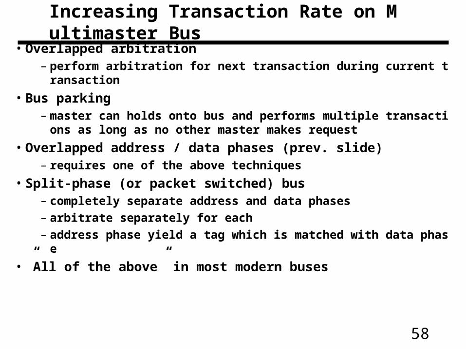
• Overlapped arbitration– perform arbitration for next transaction during current transaction
• Bus parking– master can holds onto bus and performs multiple transactions as long a
s no other master makes request
• Overlapped address / data phases (prev. slide)– requires one of the above techniques
• Split-phase (or packet switched) bus– completely separate address and data phases
– arbitrate separately for each
– address phase yield a tag which is matched with data phase
• ”All of the above” in most modern buses
Increasing Transaction Rate on Multimaster Bus
59
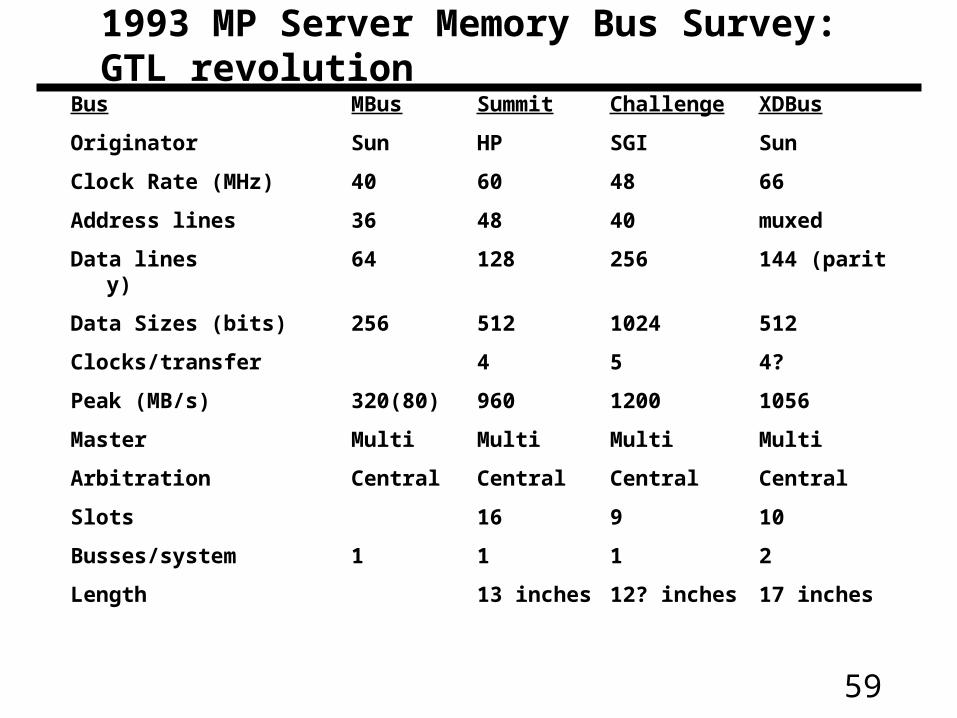
Bus MBus Summit Challenge XDBus
Originator Sun HP SGI Sun
Clock Rate (MHz) 40 60 48 66
Address lines 36 48 40 muxed
Data lines 64 128 256 144 (parity)
Data Sizes (bits) 256 512 1024 512
Clocks/transfer 4 5 4?
Peak (MB/s) 320(80) 960 1200 1056
Master Multi Multi Multi Multi
Arbitration Central Central Central Central
Slots 16 9 10
Busses/system 1 1 1 2
Length 13 inches 12? inches 17 inches
1993 MP Server Memory Bus Survey: GTL revolution
60
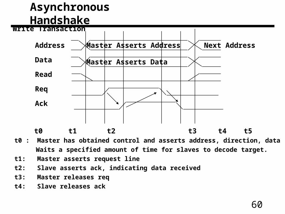
Address
Data
Read
Req
Ack
Master Asserts Address
Master Asserts Data
Next Address
Write Transaction
t0 t1 t2 t3 t4 t5t0 : Master has obtained control and asserts address, direction, data
Waits a specified amount of time for slaves to decode target.
t1: Master asserts request line
t2: Slave asserts ack, indicating data received
t3: Master releases req
t4: Slave releases ack
Asynchronous Handshake

61
Address
Data
Read
Req
Ack
Master Asserts Address Next Address
t0 t1 t2 t3 t4 t5
t0 : Master has obtained control and asserts address, direction, data
Waits a specified amount of time for slaves to decode target.
t1: Master asserts request line
t2: Slave asserts ack, indicating ready to transmit data
t3: Master releases req, data received
t4: Slave releases ack
Read Transaction
Slave Data
62
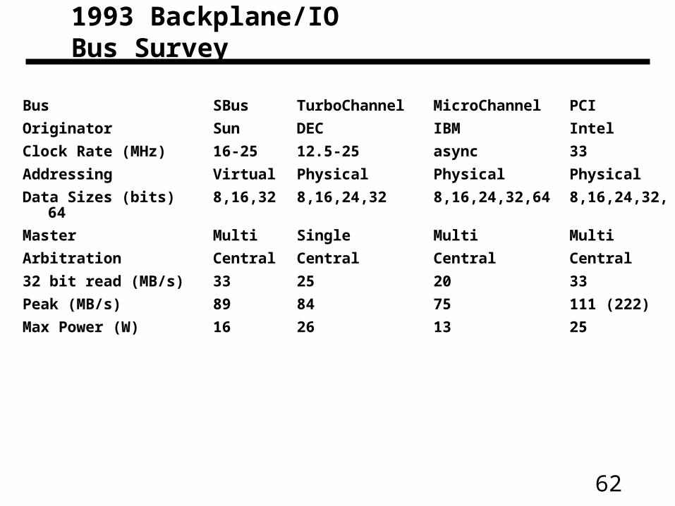
Bus SBus TurboChannel MicroChannel PCI
Originator Sun DEC IBM Intel
Clock Rate (MHz) 16-25 12.5-25 async 33
Addressing Virtual Physical Physical Physical
Data Sizes (bits) 8,16,32 8,16,24,32 8,16,24,32,64 8,16,24,32,64
Master Multi Single Multi Multi
Arbitration Central Central Central Central
32 bit read (MB/s) 33 25 20 33
Peak (MB/s) 89 84 75 111 (222)
Max Power (W) 16 26 13 25
1993 Backplane/IO Bus Survey
63
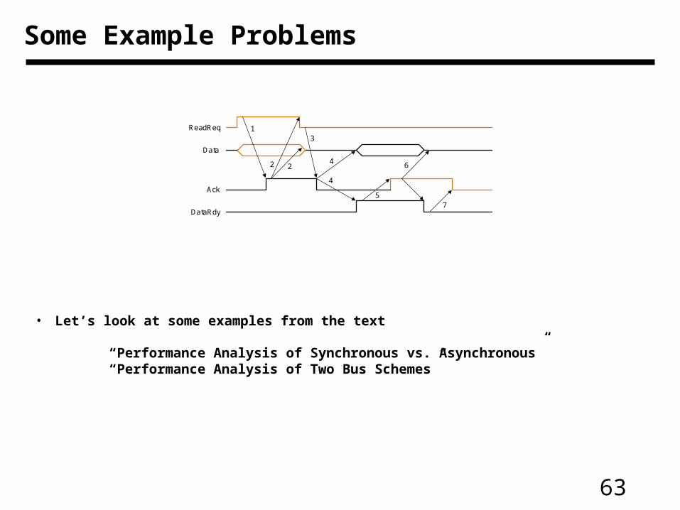
Some Example Problems
• Let’s look at some examples from the text
“Performance Analysis of Synchronous vs. Asynchronous”“Performance Analysis of Two Bus Schemes”
DataRdy
Ack
Data
ReadReq 13
4
57
642 2
64
Other important issues
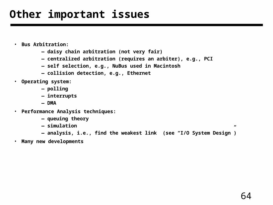
• Bus Arbitration:
— daisy chain arbitration (not very fair)
— centralized arbitration (requires an arbiter), e.g., PCI
— self selection, e.g., NuBus used in Macintosh
— collision detection, e.g., Ethernet
• Operating system:
— polling
— interrupts
— DMA
• Performance Analysis techniques:
— queuing theory
— simulation
— analysis, i.e., find the weakest link (see “I/O System Design”)
• Many new developments
65
Giving Commands to I/O Devices• Two methods are used to address the device:
– Special I/O instructions
– Memory-mapped I/O
• Special I/O instructions specify:
– Both the device number and the command word
• Device number: the processor communicates this via aset of wires normally included as part of the I/O bus
• Command word: this is usually send on the bus’s data lines• Memory-mapped I/O:
– Portions of the address space are assigned to I/O device
– Read and writes to those addresses are interpretedas commands to the I/O devices
– User programs are prevented from issuing I/O operations directly:
• The I/O address space is protected by the address translation
66
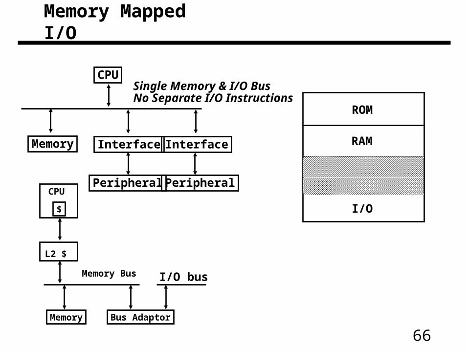
Single Memory & I/O Bus No Separate I/O Instructions
CPU
Interface Interface
Peripheral Peripheral
Memory
ROM
RAM
I/O$
CPU
L2 $
Memory Bus
Memory Bus Adaptor
I/O bus
Memory Mapped I/O
67
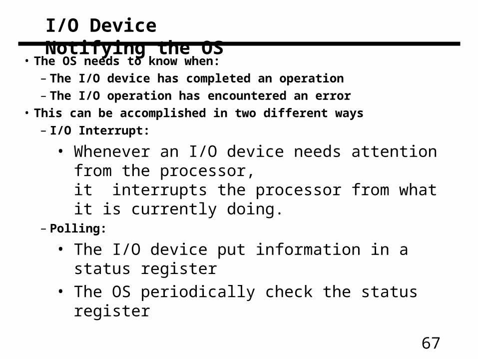
I/O Device Notifying the OS
• The OS needs to know when:
– The I/O device has completed an operation
– The I/O operation has encountered an error
• This can be accomplished in two different ways
– I/O Interrupt:
• Whenever an I/O device needs attention from the processor,it interrupts the processor from what it is currently doing.
– Polling:
• The I/O device put information in a status register
• The OS periodically check the status register
68
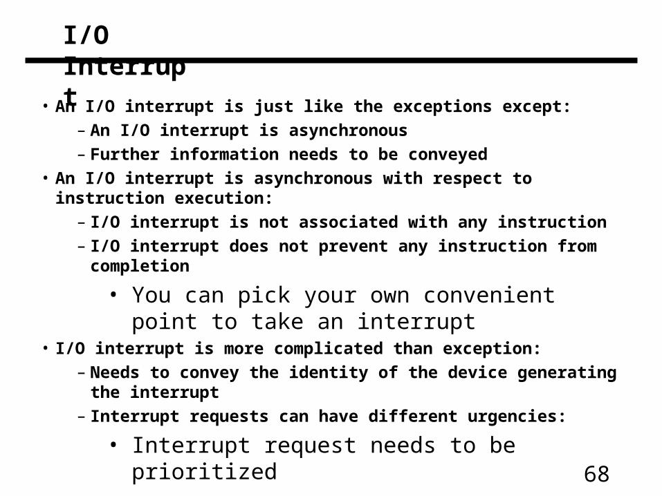
I/O Interrupt
• An I/O interrupt is just like the exceptions except:
– An I/O interrupt is asynchronous
– Further information needs to be conveyed
• An I/O interrupt is asynchronous with respect to instruction execution:
– I/O interrupt is not associated with any instruction
– I/O interrupt does not prevent any instruction from completion
• You can pick your own convenient point to take an interrupt
• I/O interrupt is more complicated than exception:
– Needs to convey the identity of the device generating the interrupt
– Interrupt requests can have different urgencies:
• Interrupt request needs to be prioritized
69
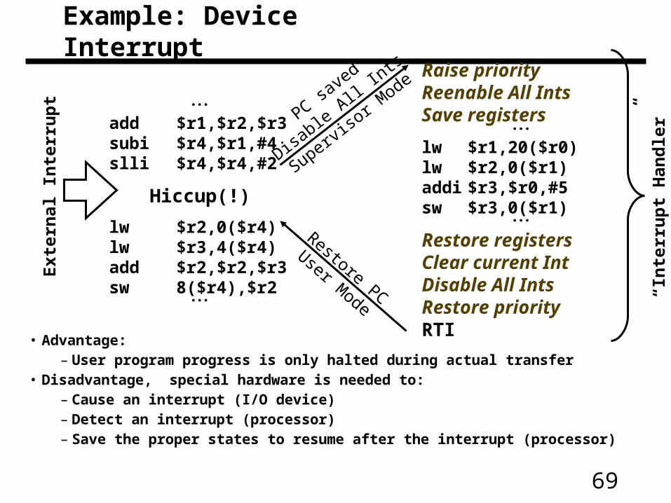
add $r1,$r2,$r3subi $r4,$r1,#4slli $r4,$r4,#2
Hiccup(!)
lw $r2,0($r4)lw $r3,4($r4)add $r2,$r2,$r3sw 8($r4),$r2
Raise priorityReenable All IntsSave registers
lw $r1,20($r0)lw $r2,0($r1)addi $r3,$r0,#5sw $r3,0($r1)
Restore registersClear current IntDisable All IntsRestore priorityRTI
Ext
erna
l Int
erru
pt
PC saved
Disable
All Ints
Superviso
r Mode
Restore PC
User Mode
“Int
erru
pt H
andl
er”
Example: Device Interrupt
• Advantage:– User program progress is only halted during actual transfer
• Disadvantage, special hardware is needed to:– Cause an interrupt (I/O device)– Detect an interrupt (processor)– Save the proper states to resume after the interrupt (processor)
70
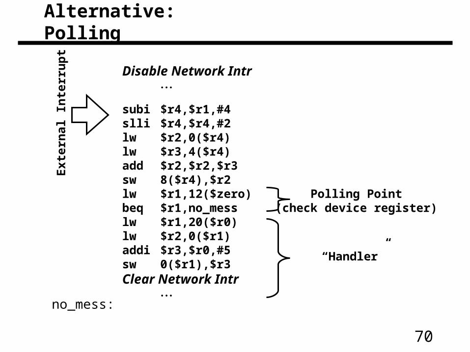
Disable Network Intr
subi $r4,$r1,#4slli $r4,$r4,#2lw $r2,0($r4)lw $r3,4($r4)add $r2,$r2,$r3sw 8($r4),$r2lw $r1,12($zero)beq $r1,no_messlw $r1,20($r0)lw $r2,0($r1)addi $r3,$r0,#5sw 0($r1),$r3Clear Network Intr
Exte
rnal In
terr
up
t
“Handler”
no_mess:
Polling Point(check device register)
Alternative: Polling
71
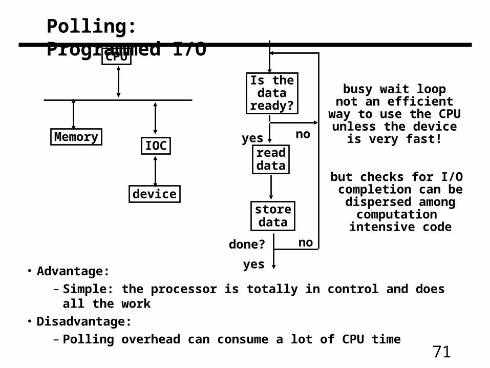
Polling: Programmed I/O
• Advantage:
– Simple: the processor is totally in control and does all the work
• Disadvantage:
– Polling overhead can consume a lot of CPU time
CPU
IOC
device
Memory
Is thedata
ready?
readdata
storedata
yes no
done? no
yes
busy wait loopnot an efficient
way to use the CPUunless the device
is very fast!
but checks for I/O completion can bedispersed among
computation intensive code
72
• Polling is faster than interrupts because
– Compiler knows which registers in use at polling point. Hence, do not need to save and restore registers (or not as many).
– Other interrupt overhead avoided (pipeline flush, trap priorities, etc).
• Polling is slower than interrupts because
– Overhead of polling instructions is incurred regardless of whether or not handler is run. This could add to inner-loop delay.
– Device may have to wait for service for a long time.
• When to use one or the other?
– Multi-axis tradeoff
• Frequent/regular events good for polling, as long as device can be controlled at user level.
• Interrupts good for infrequent/irregular events
• Interrupts good for ensuring regular/predictable service of events.
Polling is faster/slower than Interrupts
73
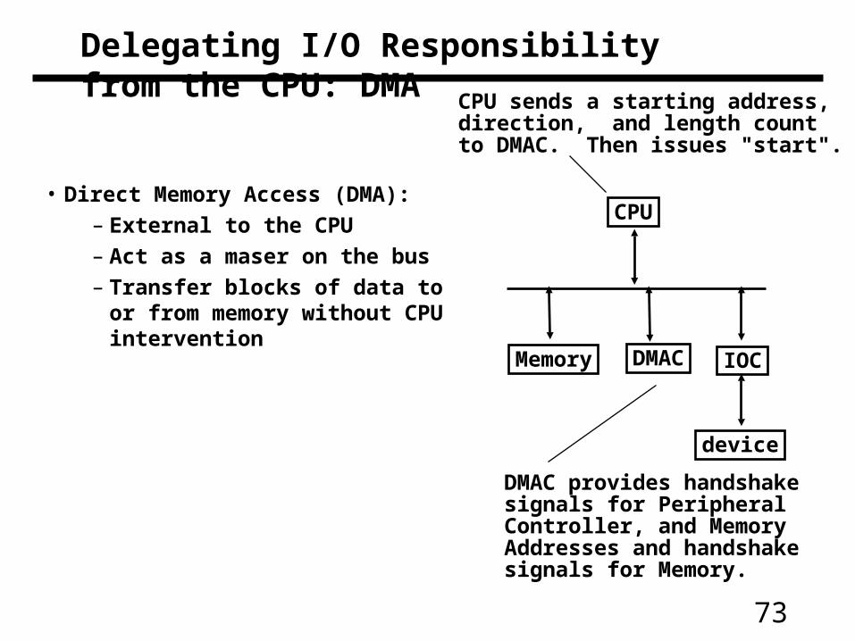
Delegating I/O Responsibility from the CPU: DMA
• Direct Memory Access (DMA):
– External to the CPU
– Act as a maser on the bus
– Transfer blocks of data to or from memory without CPU intervention
CPU
IOC
device
Memory DMAC
CPU sends a starting address, direction, and length count to DMAC. Then issues "start".
DMAC provides handshakesignals for PeripheralController, and MemoryAddresses and handshakesignals for Memory.
74
Delegating I/O Responsibility from the CPU: IOP
CPU IOP
Mem
D1
D2
Dn
. . .main memory
bus
I/Obus
CPU
IOP
(1) Issuesinstructionto IOP
memory
(2)
(3)
Device to/from memorytransfers are controlledby the IOP directly.
IOP steals memory cycles.
OP Device Address
target devicewhere cmnds are
IOP looks in memory for commands
OP Addr Cnt Other
whatto do
whereto putdata
howmuch
specialrequests
(4) IOP interrupts CPU when done
75
Responsibilities of the Operating System
• The operating system acts as the interface between:
– The I/O hardware and the program that requests I/O
• Three characteristics of the I/O systems:
– The I/O system is shared by multiple program using the processor
– I/O systems often use interrupts (external generated exceptions) to communicate information about I/O operations.
• Interrupts must be handled by the OS because they cause a transfer to supervisor mode
– The low-level control of an I/O device is complex:
• Managing a set of concurrent events
• The requirements for correct device control are very detailed
76
Operating System Requirements
• Provide protection to shared I/O resources
– Guarantees that a user’s program can only access theportions of an I/O device to which the user has rights
• Provides abstraction for accessing devices:
– Supply routines that handle low-level device operation
• Handles the interrupts generated by I/O devices
• Provide equitable access to the shared I/O resources
– All user programs must have equal access to the I/O resources
• Schedule accesses in order to enhance system throughput
77
OS and I/O Systems Communication Requirements
• The Operating System must be able to prevent:
– The user program from communicating with the I/O device directly
• If user programs could perform I/O directly:
– Protection to the shared I/O resources could not be provided
• Three types of communication are required:
– The OS must be able to give commands to the I/O devices
– The I/O device must be able to notify the OS when the I/O device has completed an operation or has encountered an error
– Data must be transferred between memory and an I/O device
78
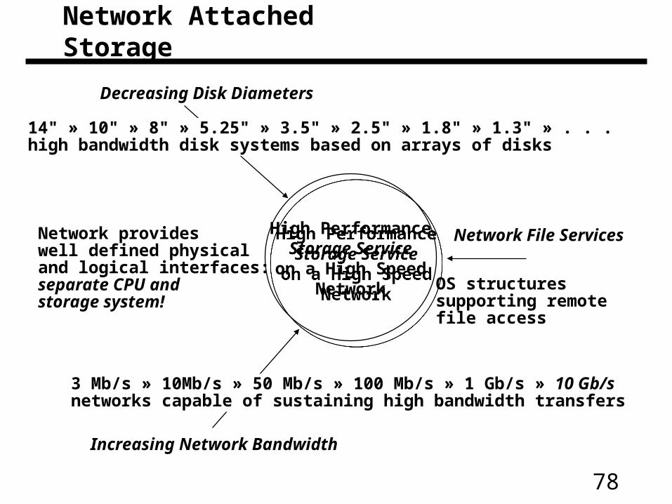
Decreasing Disk Diameters
Increasing Network Bandwidth
Network File ServicesHigh PerformanceStorage Serviceon a High Speed
Network
High PerformanceStorage Serviceon a High Speed
Network
14" » 10" » 8" » 5.25" » 3.5" » 2.5" » 1.8" » 1.3" » . . .high bandwidth disk systems based on arrays of disks
3 Mb/s » 10Mb/s » 50 Mb/s » 100 Mb/s » 1 Gb/s » 10 Gb/snetworks capable of sustaining high bandwidth transfers
Network provideswell defined physicaland logical interfaces:separate CPU and storage system!
OS structuressupporting remotefile access
Network Attached Storage