Embed Size (px)
Citation preview

1
Chapters 24 and 26.4-26.5
2
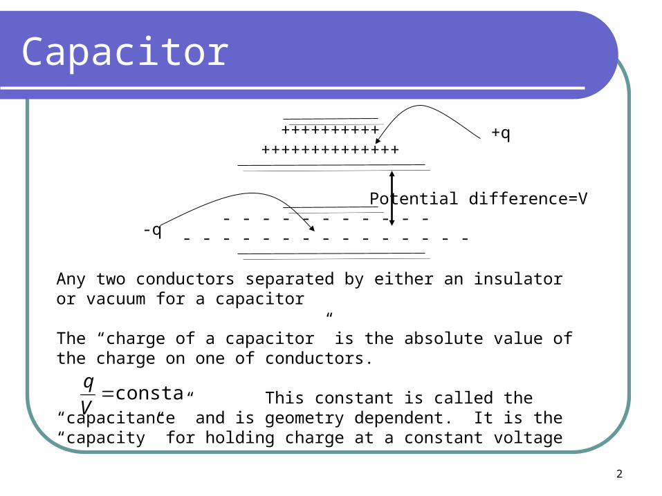
Capacitor
++++++++++++++++++++++++
- - - - - - - - - - - - - - - - - - - - - - - - - -
+q
-q
Any two conductors separated by either an insulator or vacuum for a capacitor
The “charge of a capacitor” is the absolute value of the charge on one of conductors.
This constant is called the “capacitance” and is geometry dependent. It is the “capacity” for holding charge at a constant voltage
Potential difference=V
constantV
q
3
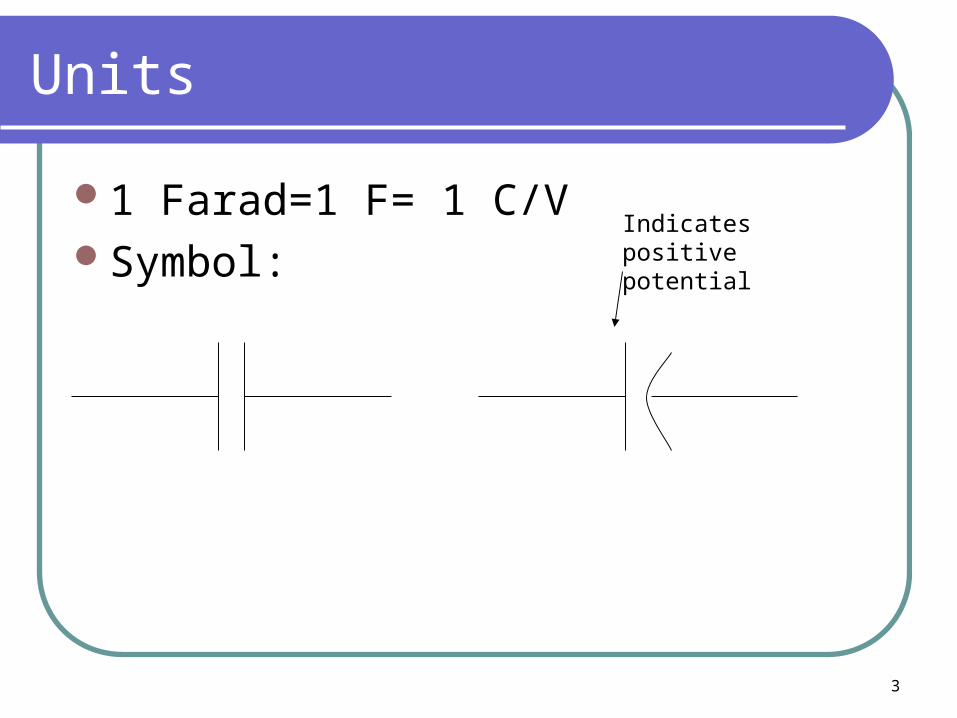
Units
1 Farad=1 F= 1 C/VSymbol:
Indicates positive potential
4
Interesting Fact
When a capacitor has reached full charge, q, then it is often useful to think of the capacitor as a battery which supplies EMF to the circuit.
5
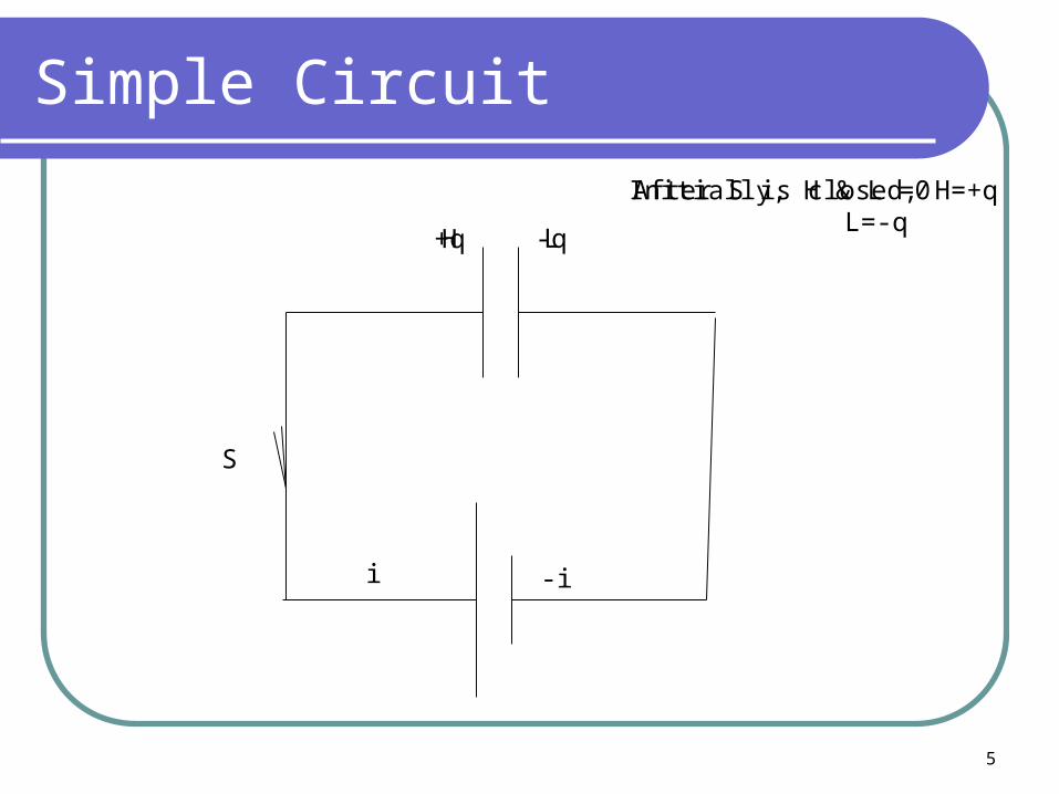
Simple Circuit
S
H L
Initially, H & L =0
+q
i -i
-q
After S is closed, H=+qL=-q
6
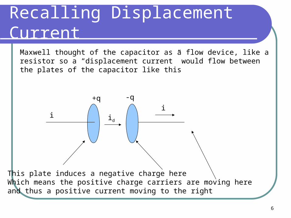
Recalling Displacement Current
i
+q -q
iid
This plate induces a negative charge hereWhich means the positive charge carriers are moving here and thus a positive current moving to the right
Maxwell thought of the capacitor as a flow device, like a resistor so a “displacement current” would flow between the plates of the capacitor like this
7
If conductors had area, A
Then current density would beJd=id/A

8
Calculating Capacitance
Calculate the E-field in terms of charge and geometrical conditions
Calculate the voltage by integrating the E-field.
You now have V=q*something and since q=CV then 1/something=capacitance
9
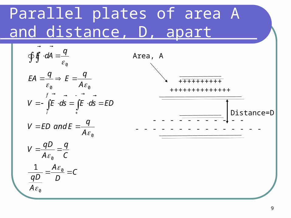
Parallel plates of area A and distance, D, apart
CD
A
AqD
C
q
A
qDV
A
qEandEDV
EDsdEsdEV
A
qE
qEA
qAdE
f
i
0
0
0
0
00
0
1
++++++++++++++++++++++++
- - - - - - - - - - - - - - - - - - - - - - - - - -
Distance=D
Area, A
10
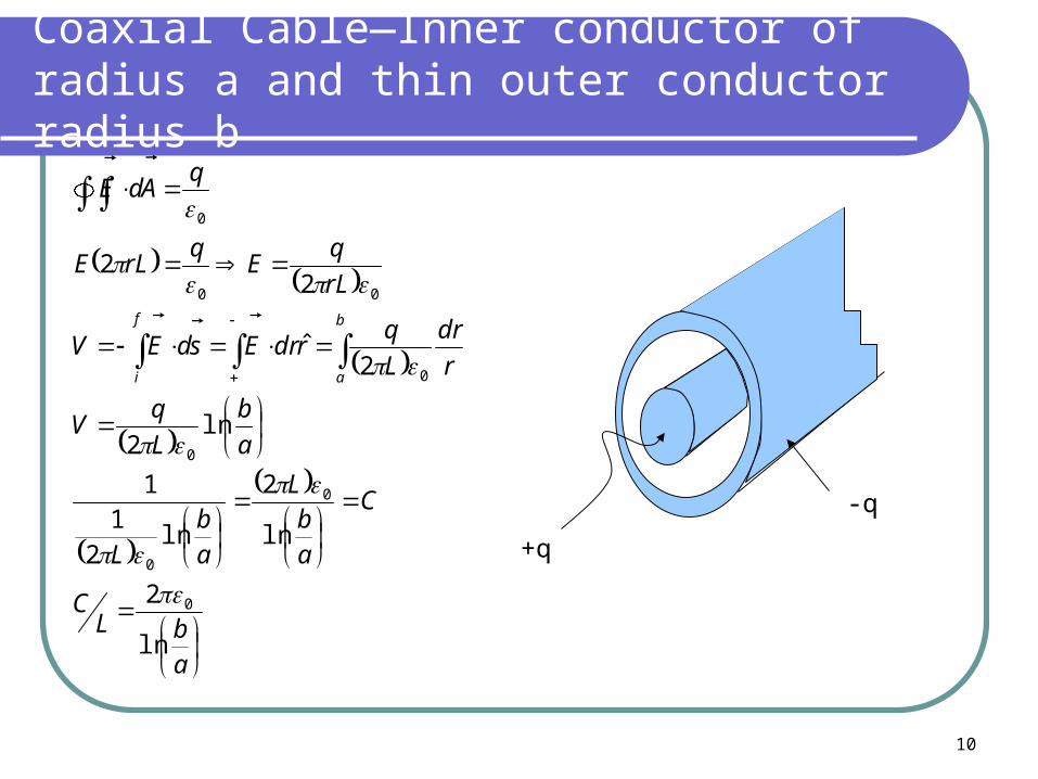
Coaxial Cable—Inner conductor of radius a and thin outer conductor radius b
+q
-q
abL
C
C
ab
L
ab
L
a
b
L
qV
r
dr
L
qrdrEsdEV
rL
qE
qrLE
qAdE
b
a
f
i
ln
2
ln
2
ln2
11
ln2
2ˆ
22
0
0
0
0
0
00
0
11
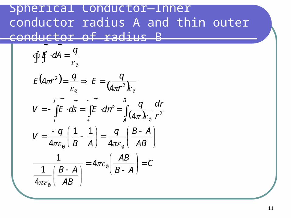
Spherical Conductor—Inner conductor radius A and thin outer conductor of radius B
CAB
AB
ABAB
AB
ABq
AB
qV
r
drqrdrEsdEV
r
qE
qrE
qAdE
B
A
f
i
0
0
00
20
02
0
2
0
4
41
1
4
11
4
4ˆ
44

12
Isolated Sphere of radius A
AC
A
qV
BLetAB
qV
0
0
0
4
4
11
4
13
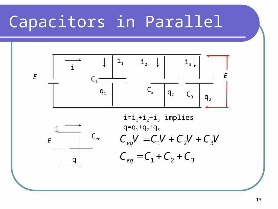
Capacitors in Parallel
E C1
C2 C3
CeqE
E
i1 i2 i3i
i
i=i1+i2+i3 implies q=q1+q2+q3
321
321
CCCC
VCVCVCVC
eq
eq
q
q1 q2 q3

14
Capacitors in Series
EC1
i
i q
q
qC2
C3
By the loop rule,E=V1+V2+V3
E Ceq
321
321
321
1111
CCCC
C
q
C
q
C
q
C
q
C
q
C
q
C
qE
C
qE
eq
eq
eq
15
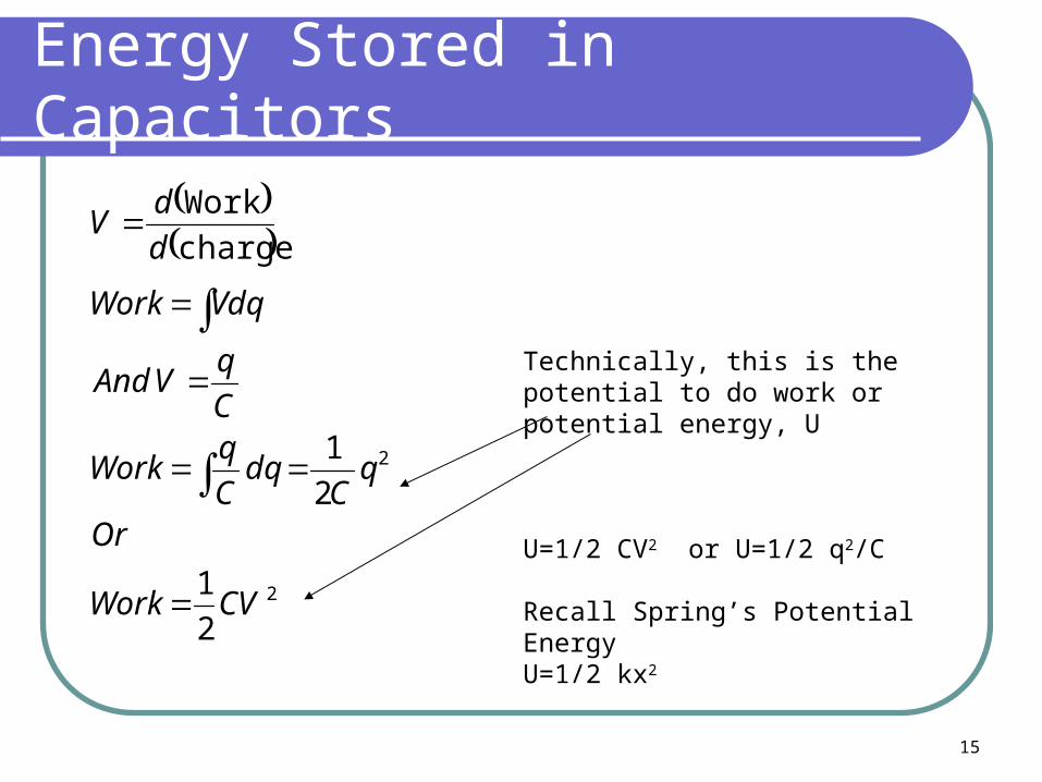
Energy Stored in Capacitors
2
2
2
1
2
1
charge
Work
CVWork
Or
qC
dqC
qWork
C
qVAnd
VdqWork
d
dV
Technically, this is the potential to do work or potential energy, U
U=1/2 CV2 or U=1/2 q2/C
Recall Spring’s Potential EnergyU=1/2 kx2
16
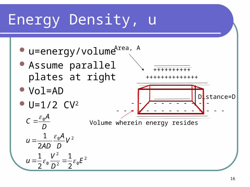
Energy Density, u
u=energy/volume Assume parallel
plates at right Vol=AD U=1/2 CV2
++++++++++++++++++++++++
- - - - - - - - - - - - - - - - - - - - - - - - - -
Distance=D
Area, A
Volume wherein energy resides
202
2
0
20
0
2
1
2
1
2
1
ED
Vu
VD
A
ADu
D
AC

17
Dielectrics
++++++++++++++++++++++++
- - - - - - - - - - - - - - - - - - - - - - - - - -
Distance=D
Area, A
++++++++++++++++++++++++
- - - - - - - - - - - - - - - - - - - - - - - - - -
++++++++++++++++++++++++
- - - - - - - - - - - - - - - - - - - - - - - - - -
Insulator
Voltage at which the insulating material allows current flow (“break down”) is called the breakdown voltage1 cm of dry air has a breakdown voltage of 30 kV (wet air less)
18
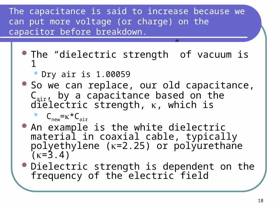
The capacitance is said to increase because we can put more voltage (or charge) on the capacitor before breakdown.
The “dielectric strength” of vacuum is 1 Dry air is 1.00059
So we can replace, our old capacitance, Cair, by a capacitance based on the dielectric strength, , which is Cnew=*Cair
An example is the white dielectric material in coaxial cable, typically polyethylene (=2.25) or polyurethane (=3.4)
Dielectric strength is dependent on the frequency of the electric field

19
Induced Charge and Polarization in Dielectrics
++++++++++++++++++++++
- - - - - - - - - - - - - - - - - - - - - - -
-- - - - - - - - - - - - - - - - - -
+++++++++++++++++++
E0Ei
ETotal=E0-Ei
11
00
0
00
0
i
i
E
EE
Note that the charges have separated or polarized

20
Permittivity of the Dielectric
0
For real materials, we define a “D-field” where D=0E
For these same materials, there can be a magnetization based on the magnetic susceptibility, , : H= B
adD
tisdH
qadD
D
Dfree
free
enclosed
enclosed
21
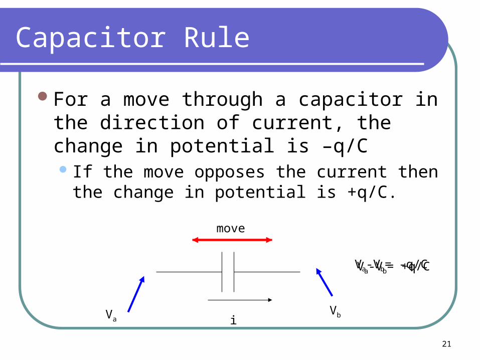
Capacitor Rule
For a move through a capacitor in the direction of current, the change in potential is –q/C If the move opposes the current then the
change in potential is +q/C.
i
move
VaVb
Va-Vb= -q/CVa-Vb= +q/C
22
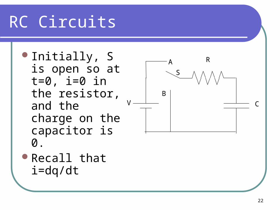
RC Circuits
Initially, S is open so at t=0, i=0 in the resistor, and the charge on the capacitor is 0.
Recall that i=dq/dt
B
A
V
S
R
C
23
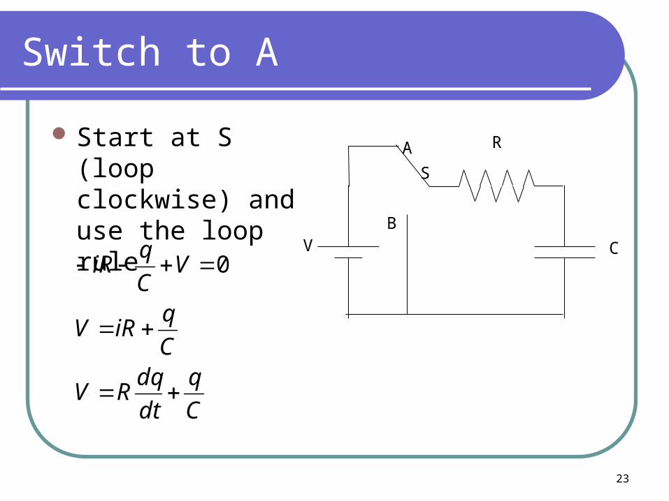
Switch to A
Start at S (loop clockwise) and use the loop rule
B
A
V
S
R
C
C
q
dt
dqRV
C
qiRV
VC
qiR
0

24
An Asatz—A guess of the solution
)1()(
0
00
0,0
:
0
RC
t
RCp
RC
t
RC
t
RC
tpRC
t
p
eCVtqCVB
BCV
BeAq
qtat
CVAorC
AV
C
BeAe
C
BV
C
q
dt
dqRV
eRC
B
dt
dqBeAqansatzMy
25
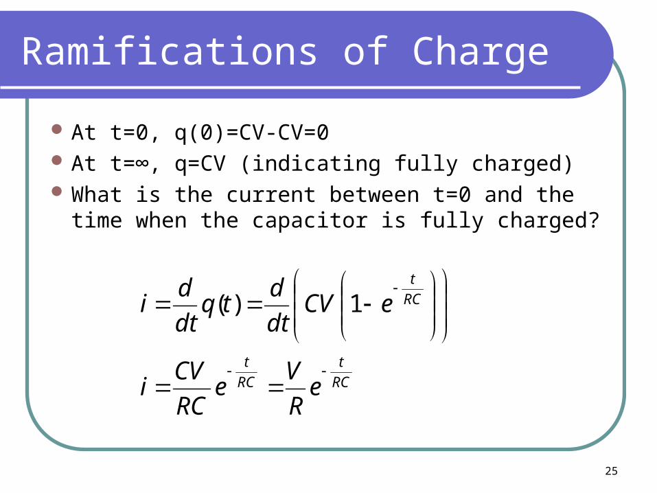
Ramifications of Charge
At t=0, q(0)=CV-CV=0 At t=∞, q=CV (indicating fully charged) What is the current between t=0 and the time
when the capacitor is fully charged?
RC
t
RC
t
RC
t
eR
Ve
RC
CVi
eCVdt
dtq
dt
di
1)(
26
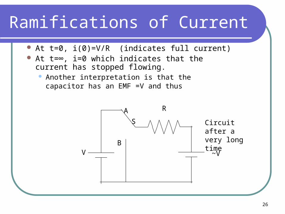
Ramifications of Current At t=0, i(0)=V/R (indicates full current) At t=∞, i=0 which indicates that the current has
stopped flowing. Another interpretation is that the capacitor has an
EMF =V and thus
B
A
V
S
R
~V
Circuit after a very long time
27
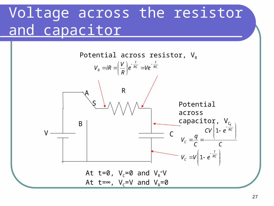
Voltage across the resistor and capacitor
B
A
V
S
R
C
RC
t
RC
t
R VeeR
ViRV
Potential across resistor, VR
RC
t
C
RC
t
C
eVV
C
eCV
C
qV
1
1
Potential across capacitor, VC
At t=0, VC=0 and VR=V
At t=∞, VC=V and VR=0
28
RC—Not just a cola
RC is called the “time constant” of the circuit
RC has units of time (seconds) and represents the time it takes for the charge in the capacitor to reach 63% of its maximum value
When RC=t, then the exponent is -1 or e-1
=RC
29
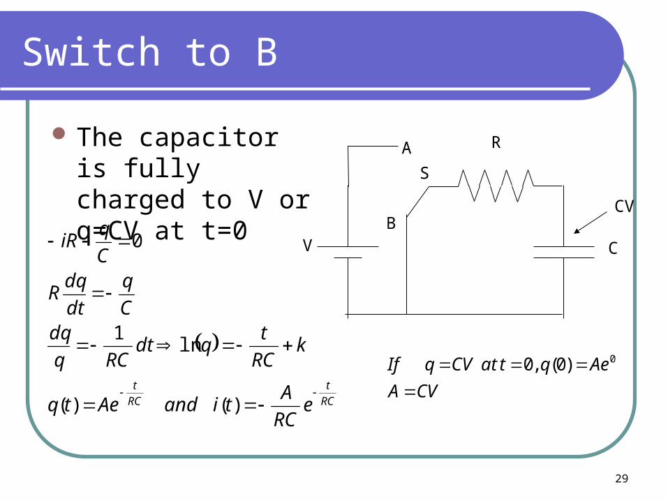
Switch to B
The capacitor is fully charged to V or q=CV at t=0
RC
t
RC
t
eRC
AtiandAetq
kRC
tqdt
RCq
dqC
q
dt
dqR
C
qiR
)()(
ln1
0B
A
V
S
R
C
CV
CVA
AeqtatCVqIf
0)0(,0
30
Ramifications
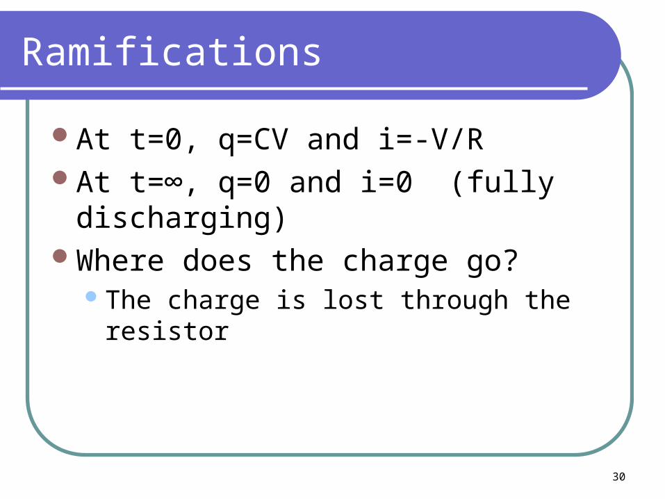
At t=0, q=CV and i=-V/RAt t=∞, q=0 and i=0 (fully discharging)Where does the charge go?
The charge is lost through the resistor
31
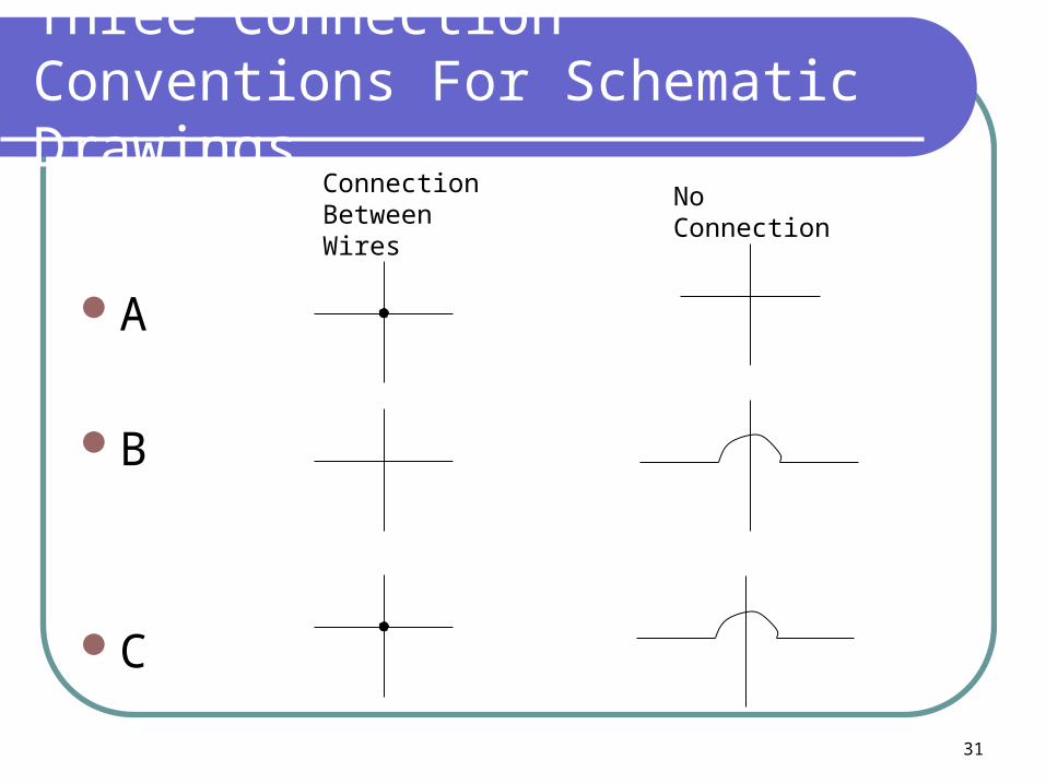
Three Connection Conventions For Schematic Drawings
A
B
C
Connection Between Wires
No Connection
32
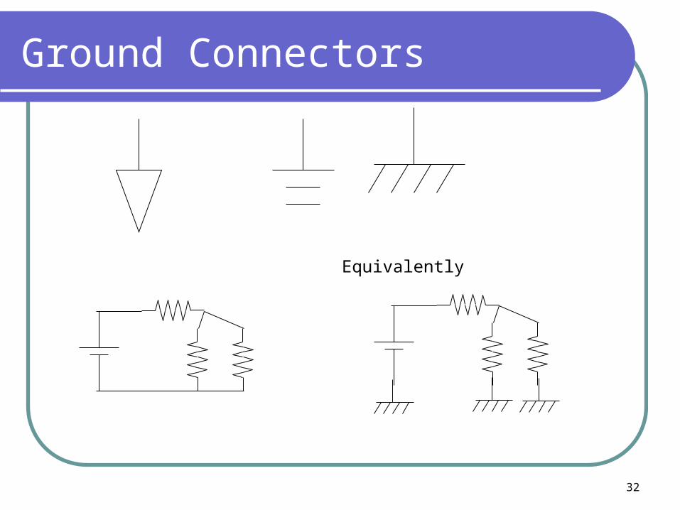
Ground Connectors
Equivalently

33
Household Wiring
“hot” or black
“return”/ “neutral” or white
“ground” or green
Normally, the “return” should be at 0 V w.r.t. ground
Single PhaseRated 20 A (NW-14)Max V 120 VAC
In THEORY, but sometimes no!

34
The Death of Little Johnny
Washerhot
neutral
Little Johnny
A short develops between the hot lead and the washer case
RG
120VRLittle Johnny
RG
If RG=∞, then Johnny is safe
Uhoh! It leaks!
If RG=0, then Johnny is dead!
X X
35
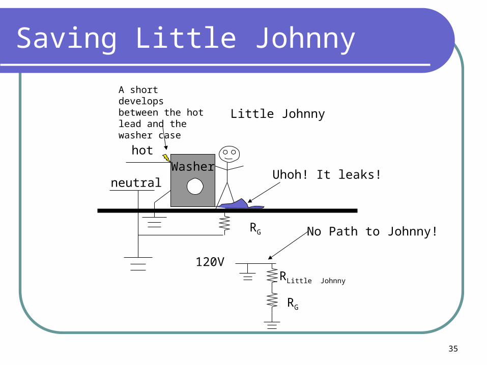
Saving Little Johnny
Washerhot
neutral
Little Johnny
A short develops between the hot lead and the washer case
RG
120VRLittle Johnny
RG
Uhoh! It leaks!
No Path to Johnny!