Embed Size (px)
Citation preview

IES M
ASTER
(1)
Class Test Solution (STRUCTURE) 17-09-2017Answer key
1. (b)
2. (b)
3. (c)
4. (a)
5. (b)
6. (a)
7. (c)
8. (c)
9. (b)
10. (d)
11. (c)
12. (d)
13. (d)
14. (c)
15. (d)
16. (a)
17. (c)
18. (d)
19. (b)
20. (c)
21. (a)
22. (a)
23. (b)
24 (b)
25. (b)
26. (b)
27. (d)
28. (c)
29. (d)
30. (a)
31. (d)
32. (b)
33. (b)
34. (c)
35. (b)
36. (c)
37. (b)
38. (c)
39. (d)
40. (c)
41. (b)
42. (a)
43. (c)
44. (c)
45. (a)
8010009955, 9711853908 [email protected], [email protected]. : E-mail:
Regd. office : Phone : F-126, (Upper Basement), Katwaria Sarai, New Delhi-110016 011-41013406
46. (b)
47. (c)
48. (d)
49 (a)
50. (c)
51. (b)
52. (c)
53 (b)
54. (d)
55. (c)
56. (b)
57. (c)
58. (c)
59. (c)
60. (c)
61. (b)
62. (d)
63. (b)
64. (d)
65. (b)
66. (a)
67. (b)
68. (a)
69. (a)
70. (c)
71. (b)
72. (a)
73. (d)
74. (c)
75. (a)

(2) CIVIL ENGINEERING CLASS TEST (STRUCTURE)
IES M
ASTER
8010009955, 9711853908 [email protected], [email protected]. : E-mail:
Regd. office : Phone : F-126, (Upper Basement), Katwaria Sarai, New Delhi-110016 011-41013406
CLASS TEST [STRUCTURE] SOLUTIONS
1. (b)2. (b)
No. of cuts in (i) required = 4
No. of restraint required = 4 – 1 = 3
DS = 3 × 4 – 3 = 9
No. of cuts in (ii) required = 4
No. of restraint required = 2 – 1 = 1
DS = 3 × 4 – 1 = 11
3. (c)Unknown displacement are
BA BC yB C D, , , , i.e., DK = 54. (a)
The unknown displacements are
A BA BC yB CD D E, , , , , ,
Since BC CB By Cy and Hence DK = 7
5. (b)No. of cuts required = 2No. of restraint required = 2DS = 3 × 2 –2 = 4
C D
A
G HE
F
B
1 2 1 2B BH c CH D G G Gy H H Hy E, , , , , ,
6. (a)
here m = 9no. of joints = j = 6
here m = 2j – 3 the pin jointed truss is internallydeterminate and stable hence it is a perfectframeif m > 2j – 3, the truss is internally indeter-minate and stableif m < 2j – 3, truss is internally unstable forsimple truss
7. (c)W1 W2 W3 W4 W5
R4R3R2R1
Nos. of reactions (unknown) = 4 (ie. R1, R2,R3, & R4) but nos. of equilibrium equationsavailable = 2 (ie. one yF 0 & another
M 0)
degree of indeterminacy = 4 – 2 = 28. (c)
If a body is sufficiently constraint by exter-nal reaction such that rigid body movementof structure does not occur, then the struc-ture is said to be stable externally.Necessary condition for this is that : There should be three reactions that are
neither concurrent nor parallel (in planestructure).
Reactions should be non-parallel, non-concurrent and non-coplanar for spacestructure (concurrent means meeting ata single point).
Parallel reaction : Inclined loading will leadto rigid body movement. Hence unstable ex-ternally.
IES M
ASTER
CLASS TEST (STRUCTURE) CIVIL ENGINEERING (3)
8010009955, 9711853908 [email protected], [email protected]. : E-mail:
Regd. office : Phone : F-126, (Upper Basement), Katwaria Sarai, New Delhi-110016 011-41013406
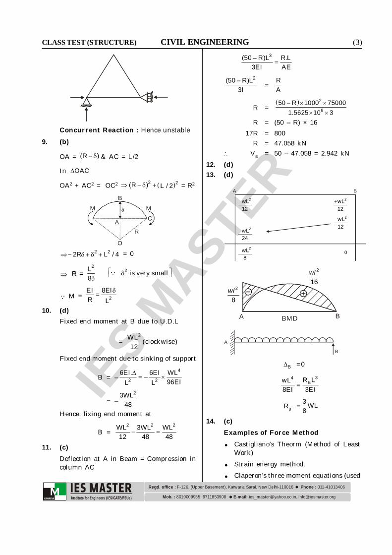
Concurrent Reaction : Hence unstable9. (b)
OA = (R ) & AC = L/2
In OAC
OA2 + AC2 = OC2 2 2(R ) L / 2 = R2
O
A
MB
CM
R
2 22R L / 4 = 0
R = 2
2L is very small8
M = 2EI 8EI=R L
10. (d)Fixed end moment at B due to U.D.L
= 2WL (clockwise)
12Fixed end moment due to sinking of support
B = –4
2 26EI. 6EI WL–
96EIL L
= –23WL
48Hence, fixing end moment at
B =2 2 2WL 3WL WL
12 48 48
11. (c)Deflection at A in Beam = Compression incolumn AC
3(50 – R)L R.L
3EI AE
2(50 – R)L3I = R
A
R = 2
950 R 1000 75000
1.5625 10 3
R = (50 – R) × 1617R = 800
R = 47.058 kN VB = 50 – 47.058 = 2.942 kN
12. (d)13. (d)
A B2 wL
12
2 wL24
2wL12
2 wL12
2 wL8
0
A BBMD
wl2
8
wl2
16
A
B
B =0
4wL8EI =
3BR L
3EI
RB = 3 WL8
14. (c)Examples of Force Method
Castigliano’s Theorm (Method of LeastWork)
Strain energy method. Claperon’s three moment equations (used

(4) CIVIL ENGINEERING CLASS TEST (STRUCTURE)
IES M
ASTER
8010009955, 9711853908 [email protected], [email protected]. : E-mail:
Regd. office : Phone : F-126, (Upper Basement), Katwaria Sarai, New Delhi-110016 011-41013406
in continous beam analysis) Column analogy method (used in rigid
frames with fixed supports) Flexibility matrix methodExamples of displacement Method Slope deflection method
Moment distribution method Stiffners matrix method Kani’s Method
15. (d)
4m
CB
A
4m
DHA
10kN/M
H
10kN/M
HA
HA
MBAMCD
HD
HD
BM = 0
MBA + 4 HA – 210 4 0
2
or, MBA+ 4HA – 80 = 0 ...(i)
Again, cM = 0
HD = – CDM4 ...(ii)
From (i)
HA = BA80 M4
H = 10 × 4
HA + HD = 40
CD BAM 80 M4 4
= 40
–MCD + 80 – MBA = 160or, MBA + MCD = –80
16. (a)
A
L
B LEI
EI
W
A
L
B LC
EI
2W
L EI
LEI EI D
E
Fig. (i) Fig. (ii)
B in fig. (i) = B in fig. (ii)
(Note the symmetricity of fig. (ii).) Fig. (ii)is nothing but Fig. (i) + its mirror imageIn fig. (ii)
MBA = B3EIL
...(1)
MBD = B D2L 2EI2W 2
8 2L
= BWL EI 32 L
B D(as )=
MBA + MBD = 0
B6EI WL=L 2
B =2WL
12EI17. (c)
A B
C45o
L
L
B Bsin45°
sin45°
CB
B
C45o
B
= B
C
B
For small B

IES M
ASTER
CLASS TEST (STRUCTURE) CIVIL ENGINEERING (5)
8010009955, 9711853908 [email protected], [email protected]. : E-mail:
Regd. office : Phone : F-126, (Upper Basement), Katwaria Sarai, New Delhi-110016 011-41013406
B sin45 sin45
= B B2 sin45 2
MBC = BB C
( 2 )2EI0 2 32 L 2 L
= BB C
32EI 2L2 L
= BB C
32 EI 2L L
18. (d)
26EI
l
26EI
l
23EI
l
3 312EI 3EI P
l l
= 3P
15EIl
19. (b)
B
A
D20 kN
1m1m
2m 2mC
E
6m
20 kN
HE
RE
RA
HA
x A EF 0 20 H H 0 ...(i)
y A EF 0 R R 20 0 ...(ii)
A E EM 0 20 1 20 2 4H 4R 0
60 + 4HE – 4RE = 0 15 + HE – RE = 0 ... (iii)
CM 0
E E E E6H 2 R R 3 H ... (iv)
From equation (iv) and equation (iii)15 + HE – 3HE = 0
15 = 2HE
HE = 7.5 kN20. (c)
Initially
A BC
M
lBA B3EIM ( ) ...(1)
BBC
3EIM
l ...(2)
BA BCM M M
BCMM2
B6EIM
lM/2
M/2l = R0l
R0 = M2
l
Fix the end C
A BC
BC B3EIM ( )
l
BBC
4EIM
l
BCB
2EIM
l
BA BCM M M
B B3EI 4EI M
l l
lB7EI M

(6) CIVIL ENGINEERING CLASS TEST (STRUCTURE)
IES M
ASTER
8010009955, 9711853908 [email protected], [email protected]. : E-mail:
Regd. office : Phone : F-126, (Upper Basement), Katwaria Sarai, New Delhi-110016 011-41013406
BMEI7
l
BA3M M7
BC4MM7
CB2MM7
4M7 2M
7l C
6M R7
> M2l
21. (a)22. (a)23. (b)
B = C = 400EI radian
DBP
A
4m
10mD
DC
By inspection, the sway would be towardsright.
P
Applying slope deflection for beam BC
MBC = 0 + B C2EI 2θ +θ10
= 2EI10
800 400+EI EI
= 240010 = 240 kNm
24. (b)Member Stiffness
OA EI3 EI3
OD 2EI4 2EI4
OC EI4 EI4
OB EI4 0.8EI5
Distribution factor for OC
= EIEI 2EI EI 0.8EI
= 14.8
Moment in member OC at O = 2004.8
Carry over factor = 12
Therefore, bending moment at
C = 200 20.83 kN-m4.8 2
25. (b)
TotalRe lative DistributionJo int Member Re lativeStiffness factorStiffness
4E(2I)CB 8 / 118
3E(I) 11EIC CD 3 / 118 8
CE 0 0
Since end E is free end, member CE haszero relative stiffness
26. (b)
L/4 L/4L/2
MEI 2
MEI
M Diagram due to fixed end momentEI
8PLEI 8
PLEI 8
PLEI
16PL
EI

IES M
ASTER
CLASS TEST (STRUCTURE) CIVIL ENGINEERING (7)
8010009955, 9711853908 [email protected], [email protected]. : E-mail:
Regd. office : Phone : F-126, (Upper Basement), Katwaria Sarai, New Delhi-110016 011-41013406
M L M L 1 PL L PL L2 2EI 4 2EI 2 2 8EI 4 16EI 2
12 16 2
PL LEI
2 2 2
2 4 32 32 64ML ML PL PL PLEI EI EI EI EI
548PLM
27. (d)28. (c)29. (d)
LL
L
The horizontal member of the frame willhave both the ends at relative leveldifference of . It is similar to
L
Fixed end moment of the horizontal
member = 26EIΔ
L.
30. (a)B CA D
EI EI EIDistribution factor for
BA =
3 I4 l
3 I I4 l l
=
34
3 14
=
3474
= 37
Distribution factor for BC = 317 = 4
7
Distribution factor for BADistribution factor forBC =
3747
= 34 = 3:4
31. (d)
A B
x
4EIL 2EI
L
B 26EIRL
A 26EIRL
L
xx
AM = 0 RB.L = 4EI 2EIL L
RB = 26EI
L
MX = 24EI 6EI x
L L = 0
(for point contraflexure)
x = 4L6 = 2L
3
32. (b)
FPQ Tension in member PQ
FPR Tension in member PR
By Lami’s theorem at point P.
FPQFPR
F
120o 135o105o
P
PRFsin135 = PQF F
sin120 sin105
FPQ =sin120 .Fsin105
= 0.8966 FFree body diagram at point Q,
FQR45oQ
FPQ
(8) CIVIL ENGINEERING CLASS TEST (STRUCTURE)
IES M
ASTER
8010009955, 9711853908 [email protected], [email protected]. : E-mail:
Regd. office : Phone : F-126, (Upper Basement), Katwaria Sarai, New Delhi-110016 011-41013406
xF = 0FQR = FQP cos 45o
FQR =0.8966 F
2 = 0.634 F
QRF 0.634 F
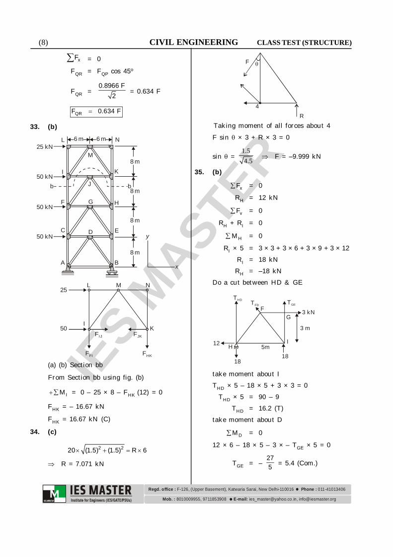
33. (b)6 m 6 m N
M
I
F
C
A B
D E
HG
J
8 m
8 m
8 m
8 m
y
x
K
25 kN
50 kN
50 kN
50 kN
b b
L
25L M N
50I
KFIJ FJK
F IF FHK
(a) (b) Section bb
From Section bb using fig. (b)
IM = 0 – 25 × 8 – FHK (12) = 0
FHK = – 16.67 kN
FHK = 16.67 kN (C)
34. (c)
2 220 (1.5) (1.5) R 6
R = 7.071 kN
F
R
4
Taking moment of all forces about 4F sin × 3 + R × 3 = 0
sin = 1 54 5.. F = –9.999 kN
35. (b)
xF = 0RH = 12 kN
vF = 0RH + RI = 0
HM = 0RI × 5 = 3 × 3 + 3 × 6 + 3 × 9 + 3 × 12
RI = 18 kNRH = –18 kN
Do a cut between HD & GE
FG
IH 5m
18
12
18
3 m
TGETFD
THD
3 kN
take moment about ITHD × 5 – 18 × 5 + 3 × 3 = 0
THD × 5 = 90 – 9THD = 16.2 (T)
take moment about D
DM = 012 × 6 – 18 × 5 – 3 × – TGE × 5 = 0
TGE = – 275 = 5.4 (Com.)

IES M
ASTER
CLASS TEST (STRUCTURE) CIVIL ENGINEERING (9)
8010009955, 9711853908 [email protected], [email protected]. : E-mail:
Regd. office : Phone : F-126, (Upper Basement), Katwaria Sarai, New Delhi-110016 011-41013406
36. (c)
A C G PZ
D
B
The nature of the forces in members havebeen depicted in the above figure.
37. (b)To calculate, horizontal diflection of the jointB, applying a force ‘p’ at B.
A 60º 60º P
RB
60º
500 3kN
C
1m
1m
AM = 0
B1500 3 0 1 R2
RB = 250 3 kN
RA = 250 3 kN
At joint c,
FCA cos 30º + FCB cos 30º = 500 3and FCA Sin 30º = FCB sin 30º FCA = FCB
2FCA3
2= 500 3
FCA = 500 kN FCB = 500 kNAt joint B,
FCB Sin 60º = 250 3 and
FBC cos 60º+P = FBA
or, FBA = P + 500 × 12 = P + 250
U = 2F L
2AEUsing castigliano’s theorem (2nd theorem)
B =
FFU P . LP AE
=
3 3
5(P 250) 1 10 10
50 2 10
=
3 3
5250 1 10 10
50 2 10 P = 0
= 2.5 mm38. (c)
7.5 kN
5 kN 5 kN10 kN
10 kN
C D
G
B
L
L
L
FA
12.5 kN
2.5 27.5 kN
F + 5L
7.5 kN 7.5 kN
F
7.5 2 kN
45°
F + 5
5 kN
F
For getting horizontal deflection at F, andload, F in the horizontal direction is applied.
MA = 0 5L + 10 L + 5 × 2L = 2L RF
RF = 252 = 12.5 kN
RA = 20 – 12.5 = 7.5 kNUsing castigliano’s method,
F =
ni i
ii ii 1
pp ·F A E
l... (i)
Where pi in member forces in the ith memberdue to combined actrion of external forcesand F. Afterward, setting F = 0 in equation

(10) CIVIL ENGINEERING CLASS TEST (STRUCTURE)
IES M
ASTER
8010009955, 9711853908 [email protected], [email protected]. : E-mail:
Regd. office : Phone : F-126, (Upper Basement), Katwaria Sarai, New Delhi-110016 011-41013406
(i) F =
i ii
i i at F 0
pp ·F A E
l
Sign conventionTensile force is taken as +ve and compressiveforce is taken as –ve. If deflection calculatedin equation (i) is the , it is in the directionof applied load at the point of desireddeflection. Otherwise opposite to thedirection of applied bad.Considering joint at D,FDG cos 45° + 5 = 12.5
FDG = 7.5 2 kN
FDC = DGF sin 45 7.5 kN
at joint B,FBG cos45°+ 5 = 7.5
FBG = 2.5 2
Thus, members having ‘F’ term involved intheir internal forces are member AG andmember GF. Thus these two members onlywill be involved in finding horizontaldeflection at point F. Other remainingmembers have no. ‘F’ term involved in theirinternal forces and on differention w.r.t forceF, will give zero term.
39. (d)
cos = 45
sin = 0.6
= 36.87º
6m
4m 4m
B
2
E
5m
CA
D
Fabrication error case (Lack of fit case)Member lengths are generally made longeror shorter than actual required length inorder to introduce member forces which willcompensate for deflection due to the deadload.Due to this lack of fit, joint deflection fromoriginal level will take place. This jointdeflection in this case is calculated usingvirtual work principle.
1. = i iu dLWhere dLi = fabrication error in ith memberSign connectiondLi = +ve if member is longer than normallyexpecteddLi = –ve if member is shorter than normallyexpectedTension = theCompression = –ve
= +ve if deflection in the direction ofapplied unit load
= –ve if deflection opposite to the directionof applied unit load.Here in question, vertical deflection is foundoutr at point c, a unit load at C in verticaldirection is applied and member forces onefound out.At joint C,
FCD sin = CD11 F 1.667
0.6
and FCD cos = CD CBF F 1.33
At joint B,FAB = FBC = 1.33
At Joint D,FED = FCD = 1.667
MemberCD –1.667 –10 +16.67CB +1.33 0 0BD 0 0 0AB +1.33 0 0AD 0 0 0DE –1.667 0 0
u DL (mm) U L(mm)
= + 16.67 mm (down)

IES M
ASTER
CLASS TEST (STRUCTURE) CIVIL ENGINEERING (11)
8010009955, 9711853908 [email protected], [email protected]. : E-mail:
Regd. office : Phone : F-126, (Upper Basement), Katwaria Sarai, New Delhi-110016 011-41013406
40. (c)Let unit load be at a distance x from freeend
l–x x1
x
2/3 ( – )l x( – )/EIl x
M diagramEI
Influence line ordinate for deflection will
be = AxEI
(moment about the free end)
yB =1 x 2x x ( x)2 EI 3
l l l
=2( x) (2 x)
2EI 3
l l
2( x) (2 x)
6EI l l .
41. (b)
3A
1
B2
B´ F DE
C
x
When load is on AB at a distance x from ARB = x/5
Now, cM RD × 6 = 2 × RB
2
F DC
x/5
24
RD =x
15MF = RD × 2
=x 2
15
At x = 0 MF = 0x = 5 MF = + 2/3.
Now, when load is on B´F at a distance yfrom C
RD × 6 = 1 × yRD = y/6
F EC
1y
2 2 2B´6B D
MF = RD × 2 y/3At y = 2 MF = 2/3
y = 4 MF = 4/3.When load is in FE at ‘y’ distance from C
MF = RD × 2 – 1 (y – 4)
y 2 – (y – 4)6
F EC
1y
4 2 2B´
At y = 6 MF = 0
y = 8MF = 8 4–(4) –3 3
.
A B F D E
4/3
4/3
2/3
42. (a)Cut section as shown :
L1 L2 L3 L4 L5L0 L6
U1 U2 U3 U4 U5
× ×6 panels @ 4m = 24m
5 m
A B
When unit load is at L2 –
RB =13 , RA =
23
2 2L UF =13 (Tension)

(12) CIVIL ENGINEERING CLASS TEST (STRUCTURE)
IES M
ASTER
8010009955, 9711853908 [email protected], [email protected]. : E-mail:
Regd. office : Phone : F-126, (Upper Basement), Katwaria Sarai, New Delhi-110016 011-41013406
When unit load is at L3 –
RA = RB = 12
2 2L UF = 12 (Compression).
43. (c)Shear in Panel LoL1
1Lo
L1 L2 L3
R = 1 R = 0
SF in Panel LoL1 = 0
LoL1 L2 L3
1
3R4
SF in Panel LoL1 = 34
LoL1 L2 L3
1
1R2
SF in Panel LoL1 = 12
L1 L2 L3
R = 14
1L0
SF in Panel LoL1 = 14
LoL1 L2 L3
R = 0
1
SF in Panel LoL1 = 0
R = F cos
F
F Rsec
Moment at L1 = R LoL1
= F cos . LoL1
1L
o 1
MF
Cos L L
ILD for force in member LoU1 is obtainedbymultiplying the ordinate of ILD for shearin panel LoL1 by sec also by dividing theordinate of ILD for moment at L1 by cos ×LoL1
44. (c)Muller Breslau theorem is valid for bothstatically determinate and indeterminatestructures.
45. (a) An influence line represents the variation
of either the reaction, shear, moment ordeflection at a specified point in amember as a concentrated unit forcemoves over the member.
Influence lines represent the effect of amoving load only at a specified point ona member whereas shear and momentdiagram represents the effect of fixedloads at all points along the member.
Thus influence line helps in deciding ata glance where should the moving loadsbe placed on the structure so that itcreates greatest influence at the specifiedpoint.
46. (b)
for K11= 214EI 4EI 8EI 2EI& KL L L L
8EIL
2EIL
4EIL
1

IES M
ASTER
CLASS TEST (STRUCTURE) CIVIL ENGINEERING (13)
8010009955, 9711853908 [email protected], [email protected]. : E-mail:
Regd. office : Phone : F-126, (Upper Basement), Katwaria Sarai, New Delhi-110016 011-41013406
Hence option (b) is correct.47. (c)48. (d)
11
4E 2I 4E 1.5I4EI 4EIK 6EI4 4 3 4
212E(2I)K EI
4
K12 = K21
49. (a)50. (c)
For equilibrium of point B, the forces mustbe balanced. Drawing reactions at point B
B
PFor balanced forces, member CB should beunder tension while member AB should beunder compression as shown in above fig-ure.Hence, neither bar AB nor BC is subjectedto bending.
51. (b)52. (c)53. (b)54. (d)
(2)B(1)
EI
(3)
EI
l
1
1
l
4EIl
4EIl
26EIl
2EIl
K23 = 2EIl
K33 = 4EI 4EI+l l = 8EI
l
K13 = 26EI–l
55. (c)56. (b)57. (c)
C
AH
RA RB
B H
h = 5 m
L = 20 m
x
C rightM = 0 10RB = 5H
H = 2RB ... (1)
C leftM = 0
10RA = 5H + P (10 – x) ...(2)From (1) and (2)
10RA = 10 RB + P (10 – x) ...(3)RA + RB = P ... (4)
From (3) and (4)10RA = 10 (P – RA) + P (10 – x)
or 20RA = 10P + 10P – Px
= 20P – Px
= P (20 – x)
RA = 20 – x P
20
Again, 10RA = 5H + P(10 – x)
20 – x P – 2P 10 – x2
= 5 H
or 20 – x P – P 20 – 2x2
= 5 H
or, 5H = xP2
H = xP10
By question,

(14) CIVIL ENGINEERING CLASS TEST (STRUCTURE)
IES M
ASTER
8010009955, 9711853908 [email protected], [email protected]. : E-mail:
Regd. office : Phone : F-126, (Upper Basement), Katwaria Sarai, New Delhi-110016 011-41013406
ARH = 2
1
20 - x P
20= 2xP
10
20 – x = 4x
5x = 20 x = 4m58. (c)
RA RBL = 25 m
xP
H HA B
C
h = 5 m
H
RRB
C rightM = 0 12.5 RB = 5H
H = 2.5 RB ... (i)By question;
tanθ = BRH = B
B
R2.5R = 1
2.5
tanθ = 0.4
59. (c)
HA HB
A
C
B
VA VB
10m y yC=10m
2kN/m
l = 40 m
AM = 0
2
B2 20 40V
2
= 0
VB = 10 kN
VA = 20 × 2 – 10 = 30 kN
CM = 0
VA × 20 – HA × 10 – 2 × 220
2 = 0
or 30 × 20 – HA × 10 – 202 = 0 HA = 20 kN
HA = HB = 20 kNBending moment at x = 10 m from A
y = c2
4y x xll
y = 24 1040
× 10 (40 – 10)
= 7.5m at 10 from A.
BM = + VA × 10 –2
A10H y 2
2
= 30×10–20×7.5 –22 10
2
= 50 kNMIf be the inclination of any point x on thecentre line of an arch, then the vertical shearVx and horizontal thrust H would combineto produce a radial shear Rx and a normalthrust Nx at the section.
ThenFx (or) Rx = xV cos H sin
andPx (or) Nx = xV sin H cos
Radial shear force at x = 10m
R = Radial shear force = V cos Hsin
where V = Net vertical shear force at x = 10m from AH = Horizontal thrust
tan = dydx =
c2
4y2x
= 12
4 10tan 40 2 1040
= 1tan 26.57=0.5
V = A
2 40V /4 30 10kN= =4

IES M
ASTER
CLASS TEST (STRUCTURE) CIVIL ENGINEERING (15)
8010009955, 9711853908 [email protected], [email protected]. : E-mail:
Regd. office : Phone : F-126, (Upper Basement), Katwaria Sarai, New Delhi-110016 011-41013406
Radial shear force,
R = V cos Hsin
= 10 × cos 26.57°– 20sin 26.57° = 0
Normal thrust at x = 10 m from ANormal thrust,
N = V sin Hcos
= 10 sin 26.57°+20 cos 26.57°= 22.36 kN
H
H
A
VA
X
RX
NX
If be the inclination of any point x on thecentre line of an arch, then the vertical shearVx and horizontal thrust H would combineto produce a radial shear Rx and a normalthrust Nx at the section.
ThenFx (or) Rx = xV cos H sin
andPx (or) Nx = xV sin H cos
60. (c)The behaviour of a structure subjected tohorizontal forces depends on its height towidth ratio. The deformation in low-risestructures where the height is smaller thanits width, is characterised predominantly byshear deformation. In high rise buildingwhere height is several times greater thanits lateral dimensions, is dominated bybending action. There are two methods-namely portal method and canti levermethod to analyse the structures subjectedto horizontal loading.Portal Method :The portal method is an approximateanalysis for analysing building framessubjected to lateral loads such as wind loads/
seismic forces.Since, shear deformations are dominant inlow rise structures, the method makessimplyfying assumptions regardinghorizontal shear in columns. Each bay of astructure is treated as a portal frame andhorizontal force is distributed equally amongthem.Assumptions in Portal Method :1. The points of inflection are located at
the mid-height of each column above thefirst floor. If the base of the column isfixed, the point of inflection is assumedat mid heght of the ground floor columnsas well otherwise, it is assumed at thehinged column base.
2. Points of inflection occur at mid span ofbeams.
3. Total horizontal shear at any floor isdistributed among the columns of thatfloor such that the exterior columnscarry half the force carried by the innercolumns.The basis of this third assumption inthe frame is composed of individualportals having one bay only.
Cantilever Method :This method is applicable to high risestructures. This is based on the simplyfingassumptions regarding the axial force incolumns.Assumptions in Cantilever Method1. The points of inflection are located at the
mid-height of each column above the firstfloor. If the base of the column is fixed,the point of inflection is assumed at midheight of the groun d floor columns aswell. Otherwise it is assumed at thehinged column base.
2. Points of inflection occur at mid span ofbeams.
3. The basic assumption of the method canbe stated as the axial force in the columnat any floor is linearly proportional to itsdistance from the centroid of all thecolumns at that level.

(16) CIVIL ENGINEERING CLASS TEST (STRUCTURE)
IES M
ASTER
8010009955, 9711853908 [email protected], [email protected]. : E-mail:
Regd. office : Phone : F-126, (Upper Basement), Katwaria Sarai, New Delhi-110016 011-41013406
61. (b)62. (d)63. (b)64. (d)
Slope deflection method is a stiffnessmethod in which unknown jointdisplacement are found out by applyingthe equilibrium condition at end .
In slope deflection equation, we use theprinciple of superposition by consideringseparately the moments developed at eachsupport due to each of the displacementA, B, and then the loads, sodisplacement at joint are independent.
65. (b)Kani’s methodGaspar Kani’s method of structural analysisis similar to cross moment distribution inthat both these methods use Gauss-Seidelliteration procedure to solve the slopedeflection equation without explicitlywritting them down. However, whereas themoment distribution method obtains theunknowns (i.e., the end moments of thestructural members) by iterating theirincrements, Kani’s method iterates theseunknowns themselves. This methodessentially consists of a single, simplenumerical operation performed repeatedly bythe joints of a structure in a chosen sequence.Results of any desired accuracy may beobtained by peforming this operation asufficient number of times using the requirednumber of significant digits. Kani’s methodis specially useful for the analysis ofmultistorey frames. It has the advantagesof simplicity, speed, economy of time, labourand space and of accuracy. However,perhaps, the two most attractive features ofthis method are as follows: It has a built-in error elimination so that
computational errors automaticallydisappear in subsequent operations. Thisalso makes possible the introduction ofany changes in loads or member lengthsthat may become necessary duringcalculations without necessitating a new
analysis. Such changes are inserted inthe computational scheme whereverrequired and the analysis simplycontinued.
It requires only one table of calculationseven for highly irregular frames withmultiple side sway. Compared to mostother methods, Kani’s method involvessubstantially less labour and time in theanalysis of such frames.The above advantages make Kani’smethod one of the most powerfultechniques applicable to all types ofcontinuous beams and frames.Moment distribution method.This method consists of solving slopedeflection equations by successiveapproximation that may be carried outto any desired degree of accuracy.Essentially, the method begins byassuming each joint of a structure isfixed. Then by unlocking and lockingeach joint in succession, the internalmoments at the joints are distributedand balanced until the joints haverotated to their final or nearly finalpositions. This method of analysis is bothrepetitive and easy to apply. Manualanalysis of gable frames mostly uses themoment distribution or slope deflectionmethods. These methods are usuallylengthy and have no built-in-errorelimination capability.
66. (a)67. (b)68. (a)69. (a)70. (c)71. (b)72. (a)73. (d)74. (c)
For a three-hinged arch subjected to verticalloads only, the horizontal support reactionsat the arch springings are equal and oppoiste

IES M
ASTER
CLASS TEST (STRUCTURE) CIVIL ENGINEERING (17)
8010009955, 9711853908 [email protected], [email protected]. : E-mail:
Regd. office : Phone : F-126, (Upper Basement), Katwaria Sarai, New Delhi-110016 011-41013406
and act inward. The vertical supportreactions at the arch springings are equalto those of a simply supported beam ofidentical length with identical loads.
V2
3H
H2
V2
H 1
V1 V2
2 HC
l
a W 3
For the above three hinged arch, the verticalreaction at support 2 is obtained byconsidering moment eqilibrium aboutsupport I.Hence M1 = 0 = lV2 – Wa and V2 = wa/l
V1 = W – V2 = w(1 – a/l).These values for V1 and V2 are identical tothe reactions of a simply supported beam ofthe same span as the arch with the sameapplied load W.The horizontal thrust at the springings isdetermined from a free body diagram of theright half of the arch. Considering momentequilibrium about the crown hinge at 3;
M3 = 0 = lV2/2 – HC H = 2l × V
2CThis value for H is identical to the bendingmoment at the centre of a simply supportedbeam of the same length with the sameapplied load W multplied by 1/C. Thebending moment in the arch at any point adistance x from the left support is given by
Mx = V1x – H.y for ax
= V2(l – x) – Hy for a < x l
where y is the height of the arch at a
distance x from the left support.The expressions for bending moment maybe considered as the superposition of thebending moment of a simply supported beamof the same span with the same applied loadW plus the bending moment due to thehorizontal thrust.
Wa( – a)/l l
BM due to horizontalthrust
HC
la
BM due to applied loadon a S.S. beam
C
BM of the three hinged archl/2 l/2
75. (a)Method of jointIn a planar-truss, at every point there aretwo conditon of equilibrium
xF = 0 and = 0
Since all the members at a joint are assumedto pass through a single point, moment aboutthe joint will always be zero. Hence,
M 0 will not be of any consequence. Thustwo unknowns can be found out from twoequilibrium equations. Likewise, we canproceed to other joints and find out memberforces by using equilibrium equation if no.of unknown forces at the joint are at mosttwo in number.


![TEMA 11: ESTRUCTURA DE BARRAS - personal.us.espersonal.us.es/ejem/wp-content/uploads/2016/02/T10-Estructuras-de-barras.pdf · 4m 2m p 30kn 4m 2m 20kn 10kn 20kn 10kn 10kn 20kn [a]](https://img.pdfslide.net/doc/110x75/5e071318e99fbf566e633757/tema-11-estructura-de-barras-4m-2m-p-30kn-4m-2m-20kn-10kn-20kn-10kn-10kn-20kn.jpg)