Embed Size (px)
Citation preview

1
CMPT 371Data Communications and
Networking
Spread Spectrum

Janice Regan © 20052
Spread SpectrumAnalog signal based on analog or digital dataBegin with data encoded in a narrow band
signal. Spread data over wider bandwidth
Can move from one narrow band to anotherCan share multiple narrow bands with other
signals

Janice Regan © 20053
Spread Spectrum ConceptInput fed into channel encoder
Narrow bandwidth analog signal around central frequency
Signal modulated using a spreading sequence/codeSequence often generated by pseudorandom number
generator
Increases bandwidth significantlySpreads each signal throughout the spectrum
Receiver uses same sequence/code to demodulate signal
Demodulated signal fed into channel decoder

Janice Regan © 20054
Model Spread Spectrum System
Stallings 2003: Figure 9.1
Janice Regan © 20055
GainsMany users can share same higher bandwidth
with little interferenceCan hide/encrypt signalsCan reduce each signal’s susceptibility to
jamming, noise and interferenceOnly receiver who knows spreading code can
retrieve signalNeed to jam a wide bandwidth to guarantee that a
particular narrow band signal is jammedNoise or interference at a particular frequency does
less damage to the signal

Janice Regan © 20056
Spread SpectrumFrequency hopping
Broadcast in a narrow frequency band whose central frequency moves from one narrow frequency band to another on a regular basis
Order of switching between bands is based on a pseudorandom sequence
Direct SequenceSignal is multiplied by a chipping code (multiple chips per
input signal bit)
Code Division Multiple Access (CDMA)Signal is spread over a wide band shared with many other
similar signals
Janice Regan © 20057
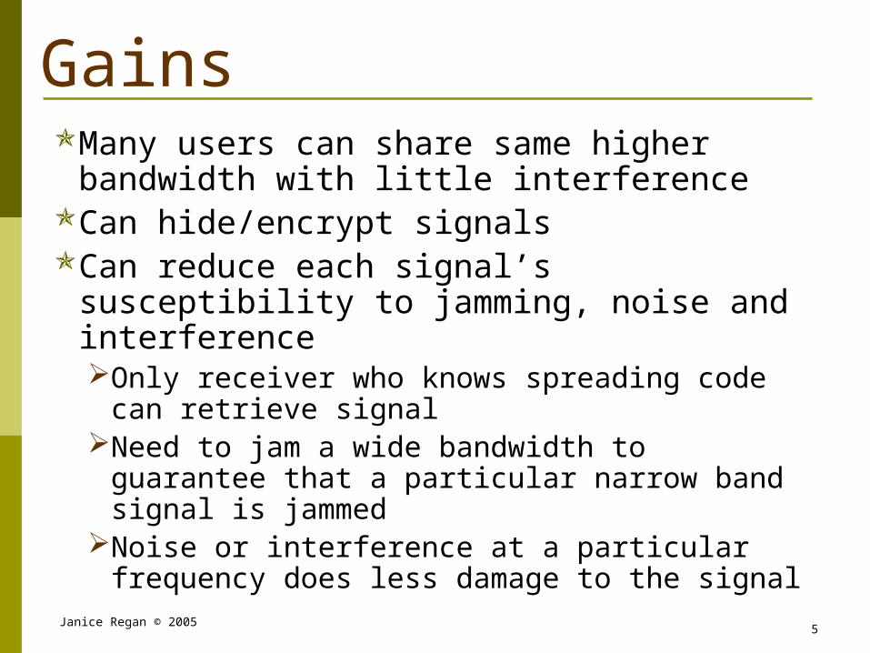
Frequency Hopping Spread Spectrum (FHSS)
Signal broadcast over pseudorandom series of frequencies
Receiver uses same pseudorandom series to know which frequencies to listen for
Receivers often use autocorrelation to synchronize pseudorandom sequence with transmitter.
Noise or jamming on one frequency affects only a few bits being transmitted at that frequency (usually these bits can be recovered using error correction)

Janice Regan © 20058
Frequency Hopping
Stallings 2003: Figure 9.2
Janice Regan © 20059
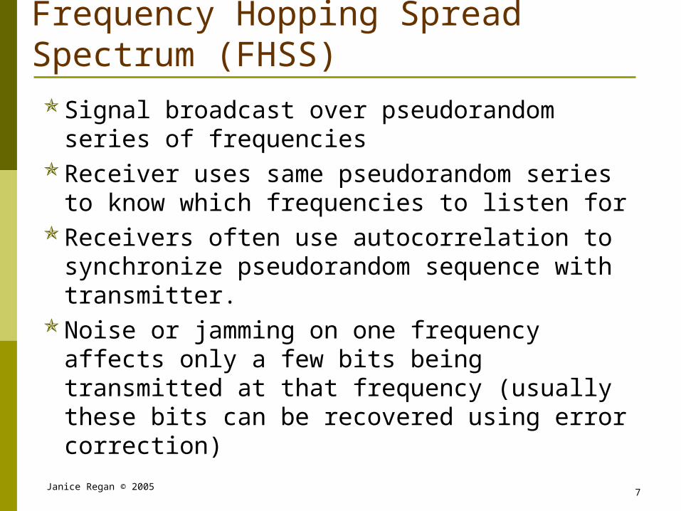
Pseudorandom Sequences
Generated by algorithm which repeatedly produces a particular known series of numbers of length n that appear to have random properties
An initial seed is used to choose where in the known sequence the particular random sequence will begin.
Algorithm is deterministic but resulting pseudorandom sequence will pass reasonable tests of randomness
Need to know algorithm and seed to predict sequenceAlgorithm will be part of protocol definitionSeed will be determined based on assigned channel,
serial number or other basis
Janice Regan © 200510
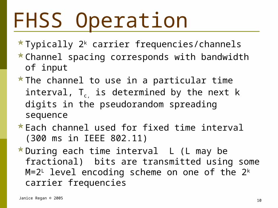
FHSS OperationTypically 2k carrier frequencies/channelsChannel spacing corresponds with bandwidth of input
The channel to use in a particular time interval, Tc, is determined by the next k digits in the pseudorandom spreading sequence
Each channel used for fixed time interval (300 ms in IEEE 802.11)
During each time interval L (L may be fractional) bits are transmitted using some M=2L level encoding scheme on one of the 2k carrier frequencies

Janice Regan © 200511
FHSS System (Transmitter)
Stallings 2003: Figure 9.3
Janice Regan © 200512
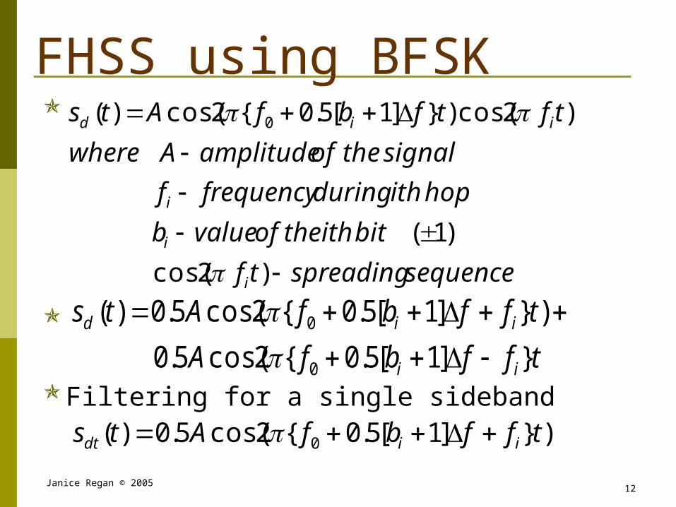
FHSS using BFSK
Filtering for a single sideband)}]1[5.0{2cos(5.0)( 0 tffbfAts iidt
sequencespreadingtf
bitiththeofvalueb
hopithduringfrequencyf
signaltheofamplitudeAwhere
tftfbfAts
i
i
i
iid
)2cos(
)1(
)2cos()}]1[5.0{2cos()( 0
tffbfA
tffbfAts
ii
iid
}]1[5.0{2cos(5.0
)}]1[5.0{2cos(5.0)(
0
0

Janice Regan © 200513
FHSS System (Receiver)
Stallings 2003: Figure 9.3
Janice Regan © 200514
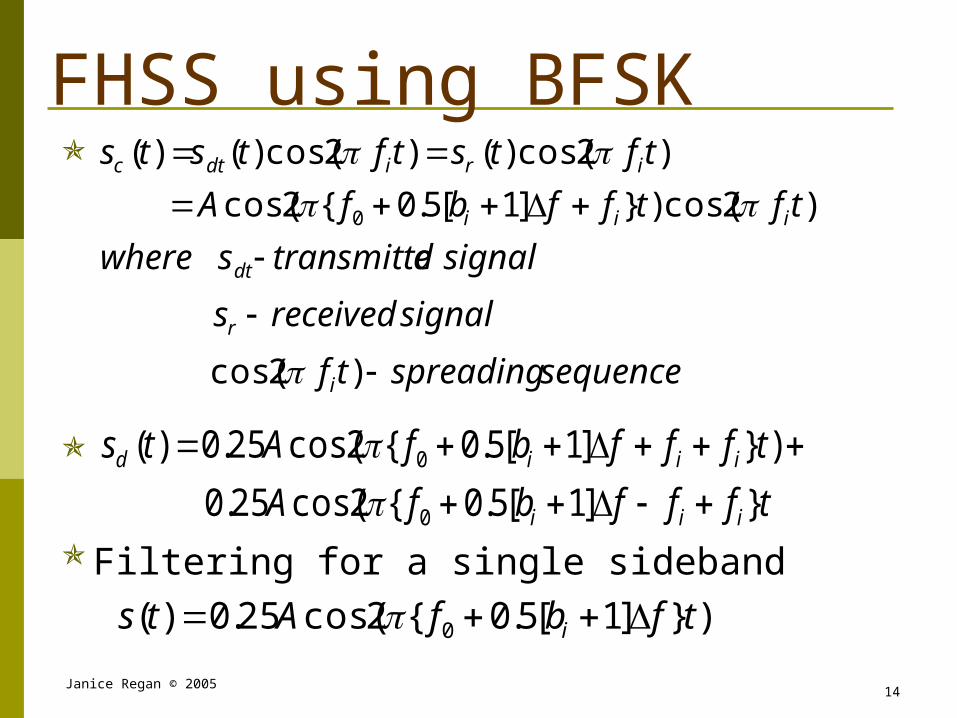
FHSS using BFSK
Filtering for a single sideband
)}]1[5.0{2cos(25.0)( 0 tfbfAts i
sequencespreadingtf
signalreceiveds
signaldtransmitteswhere
tftffbfA
tftstftsts
i
r
dt
iii
iridtc
)2cos(
)2cos()}]1[5.0{2cos(
)2cos()()2cos()()(
0
tfffbfA
tfffbfAts
iii
iiid
}]1[5.0{2cos(25.0
)}]1[5.0{2cos(25.0)(
0
0

Janice Regan © 200515
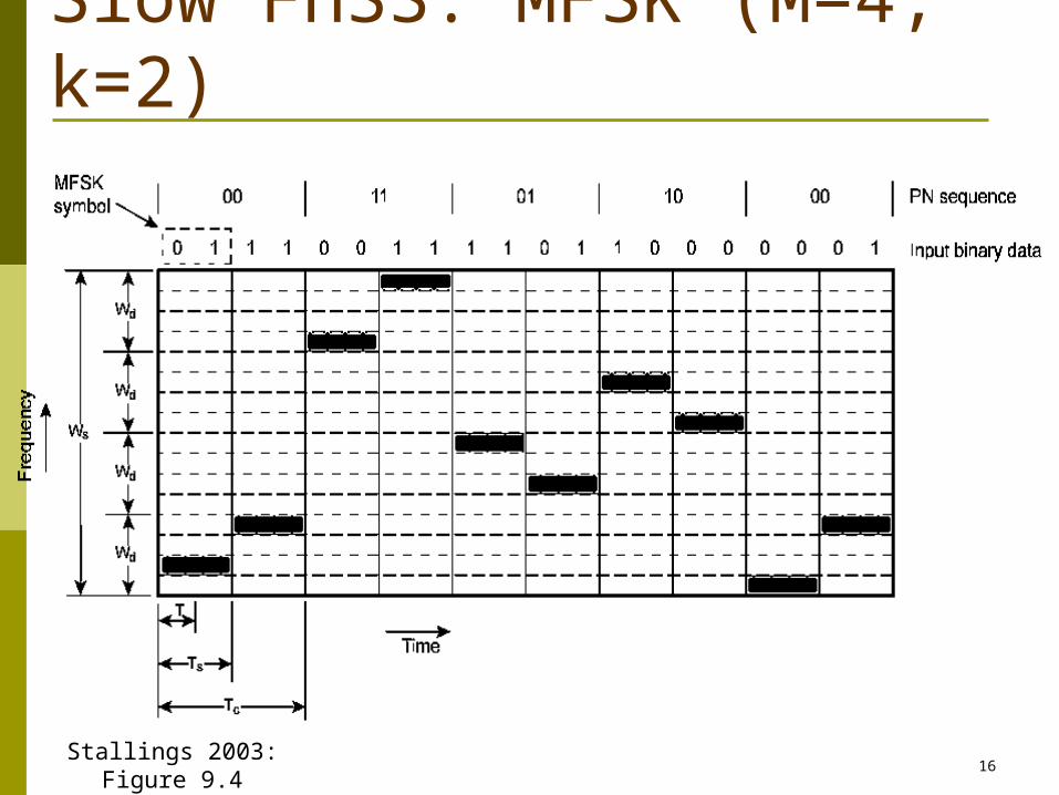
Slow and Fast FHSSTc is the chipping duration or the length of
time each channel is used for a single series of k bits in the spreading or chipping sequence. Frequency is shifted every Tc seconds
Duration of signal element is Ts secondsIf Tc Ts transmission by slow FHSSIf Tc < Ts transmission by fast FHSSGenerally fast FHSS gives improved
performance in noise (or jamming)
Janice Regan © 200516
Slow FHSS: MFSK (M=4, k=2)
Stallings 2003: Figure 9.4

Janice Regan © 200517
Fast FHSS MFSK (M=4, k=2)
Stallings 2003: Figure 9.5

Janice Regan © 200518
FHSS Performance ConsiderationsTypically large number of frequencies used so there
are many more channels than levelsProvides excellent protection against jamming, noise
and interferenceTo jam a single channel need to broadcast a signal
with the bandwidth of the channel and some power level P
To jam FHSS must jam all channels simultaneously, broadcasting a power equal to the number of channels * P (expensive and difficult)

Janice Regan © 200519
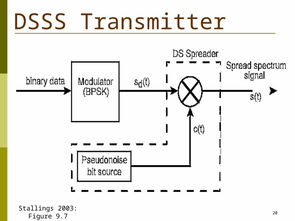
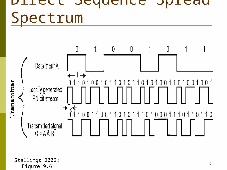
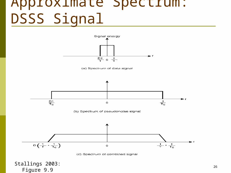
Direct Sequence Spread Spectrum (DSSS)Each bit multiplied by multiple bits of a spreading
sequenceSignal is spread across a frequency band wider than
that of the original signal. If each data bit is multiplied by n bits of the spreading sequence the bandwidth of the spread signal is n times the bandwidth of the original signal
One method:Combine input with spreading code using XORData rate equal to data rate of the original spreading code
Performance similar to FHSS
Janice Regan © 200520
DSSS Transmitter
Stallings 2003: Figure 9.7
Janice Regan © 200521
Direct Sequence Spread Spectrum
Stallings 2003: Figure 9.6

Janice Regan © 200522
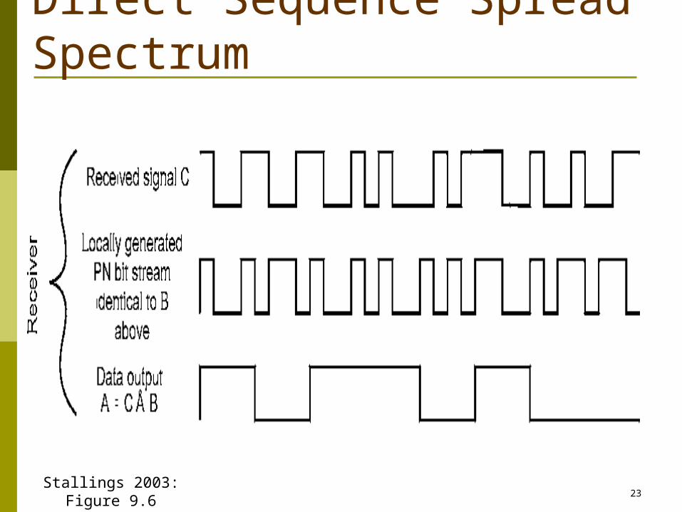
DSSS Receiver
Janice Regan © 200523
Direct Sequence Spread Spectrum
Stallings 2003: Figure 9.6
Janice Regan © 200524
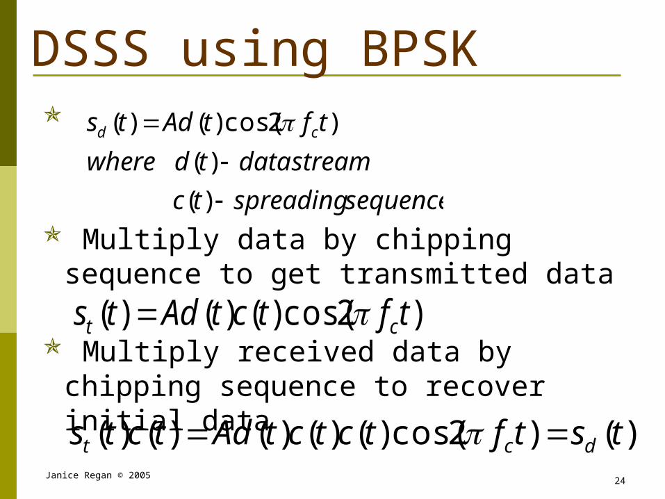
DSSS using BPSK
Multiply data by chipping sequence to get transmitted data
Multiply received data by chipping sequence to recover initial data
sequencespreadingtc
streamdatatdwhere
tftAdts cd
)(
)(
)2cos()()(
)2cos()()()( tftctAdts ct
)()2cos()()()()()( tstftctctAdtcts dct

Janice Regan © 200525
DSSS Using BPSK
Stallings 2003: Figure 9.8
Janice Regan © 200526
Approximate Spectrum: DSSS Signal
Stallings 2003: Figure 9.9
Janice Regan © 200527
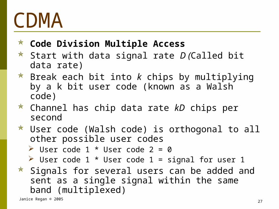
CDMA Code Division Multiple Access Start with data signal rate D (Called bit data rate) Break each bit into k chips by multiplying by a k bit
user code (known as a Walsh code) Channel has chip data rate kD chips per second User code (Walsh code) is orthogonal to all other
possible user codes User code 1 * User code 2 = 0 User code 1 * User code 1 = signal for user 1
Signals for several users can be added and sent as a single signal within the same band (multiplexed)
Janice Regan © 200528
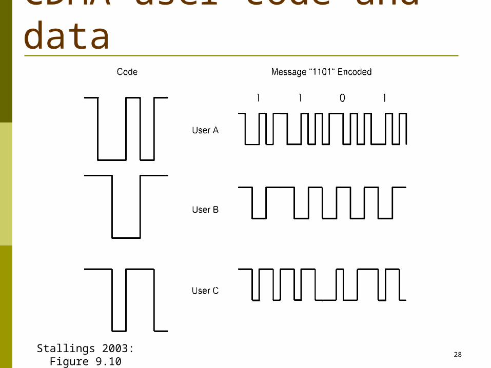
CDMA user code and data
Stallings 2003: Figure 9.10
Janice Regan © 200529
CDMA ExplanationConsider a user communicating with a base stationBase station knows user A’s codeAssume communication already synchronized Base station receives a message from A and wants to
decode it. To extract the signal from A the basestation multiplies the signal by A’s code
Decoder ignores other sources by using A’s code to decodeFor all other stations code station I * code station A = 0 so
only the signal for station A remains
Janice Regan © 200530
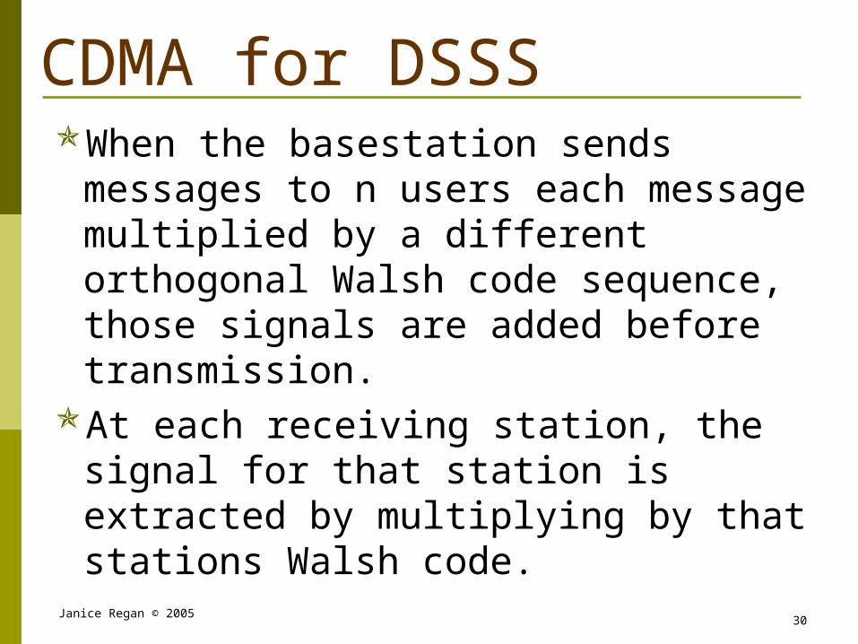
CDMA for DSSSWhen the basestation sends messages to n
users each message multiplied by a different orthogonal Walsh code sequence, those signals are added before transmission.
At each receiving station, the signal for that station is extracted by multiplying by that stations Walsh code.

Janice Regan © 200531
CDMA: two-senders, eight bit Walsh codes
Walsh Code 2
Walsh Code 1
DataStation 1
DataStation 2
Data multiplied by Walsh Code
Data multiplied by Walsh Code(Sum of all stations)
Transmitted data
Janice Regan © 200532
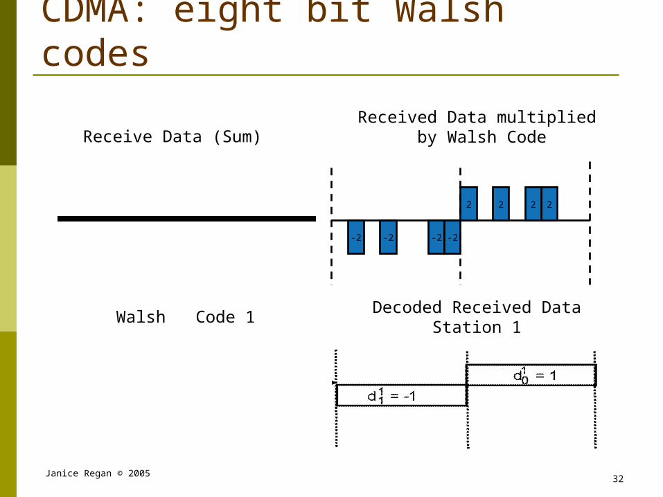
CDMA: eight bit Walsh codes
Walsh Code 1
Received Data multiplied by Walsh Code
Decoded Received DataStation 1
-2 -2 -2
2
-2
2 2 2
Receive Data (Sum)

Janice Regan © 200533
Summary of Channel PartitioningCDMA (Code Division Multiple Access) Used mostly in wireless broadcast channels such as cellular
phones All users share same frequency band. Information from each
user is spread throughout that frequency band Each user has their own orthogonal Walsh code ‘chipping’
sequence to encode data. encoded signal = (original data) X (Walsh code) Encoded signals from each channel are added, the summed
signal is transmitted The orthogonal property of Walsh codes guarantees that
(ignoring transmission errors) multiplying the received signal by a Walsh code will extract the data for the channel encoded using that Walsh code from the received (summed) signal.
Decoded signal = (received summed signal X Walsh code)
Janice Regan © 200534
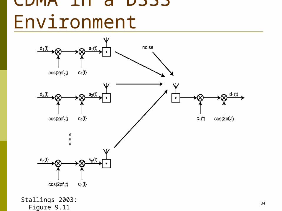
CDMA in a DSSS Environment
Stallings 2003: Figure 9.11