Embed Size (px)
Citation preview

1
Computational Fluid Dynamics Simulation of Hypersonic Engine Components
by
Jack R. Edwards
Associate Professor
Department of Mechanical and Aerospace Engineering
North Carolina State University, Raleigh, NC

2
Overview
Computational fluid dynamics simulation of hypersonic engine components – a major research thrust area in Aerospace Engineering at NCSU since the Mid 1980s.
Current areas of emphasis:
• Nose-to-tail simulations of complete engine flowfields (NASA Glenn; Edwards and McRae)
• Modeling of turbulent Schmidt number and Prandtl number effects in supersonic combustion (NASA Langley; Hassan and Edwards)
• Modeling of supercritical-fluid and barbotage injection of hydrocarbon fuels (AFRL/PRA; Edwards)
• Algorithmic enhancements to NASA’s VULCAN flow solver (NASA Langley; Edwards and McRae)
• Hybrid large-eddy / Reynolds-averaged modeling of scramjet component flowfields (NIA Seed Grant; Edwards)

3
Personnel
Dr. Jack R. Edwards, Associate Professor
• CFD algorithm development for reacting / multi-phase flows Dr. Hassan A. Hassan, Professor
• Transition and Turbulence Modeling Dr. D. Scott McRae, Professor
• Solution Adaptive Gridding Methods
Jason Norris, Keith McDaniel, Ming Tian: Ph.D. students Ana Pinto, Michael Schoen: M.S. students Adam Amar: Undergraduate research assistant

4
Unique Contributions
Low-Diffusion Flux-Splitting Schemes (LDFSS)• High-resolution upwind-differencing methods
• Extensions for real fluids, gas-solid flows, multi-phase mixture flows, chemically reacting flows, etc
• Several parallel, multi-block, implicit flow solvers built around LDFSS techniques
k- Transition / Turbulence Models• Coordinate-invariant two-equation model for wall-bounded and
free-shear flows at all speeds
• Transition model accounts for Tollmein-Schlicting, crossflow, bypass, and second-mode disturbance growth
• Predicts onset and extent of transition and has been coupled with
the Spalart-Allmaras and the k- model

5
Unique Contributions
Dynamic Solution-Adaptive Gridding Techniques• Improved feature resolution through point-clustering
• Extensions for time-accurate flows, multi-block grids with non-contiguous interfaces, unstructured grids
• Recent applications to high-speed inlet unstart and pollutant source tracking in air-quality models
Hybrid Large-Eddy / Reynolds-Averaged (LES/RANS) Simulation methods• Techniques combine RANS strategies near solid surfaces with
LES strategies further away
• Transition facilitated by flow-dependent blending functions
• Applications to shock / boundary layer interactions in internal flows

6
Resources
NCSC IBM SP-2 (720 processors, 1 teraflop; soon to be replaced with a linux Beowulf cluster)
4-processor Compaq ES-40 2-processor Microway DS-20 1-processor Compaq XP-1000 Several Sun, SGI workstations Several PCs LaTEX, Tecplot, Ensight, animation software VULCAN (NASA Langley), CHEM3D (Dow Chemical) REACTMB variants (NCSU) All codes parallelizable with MPI message-passing
7
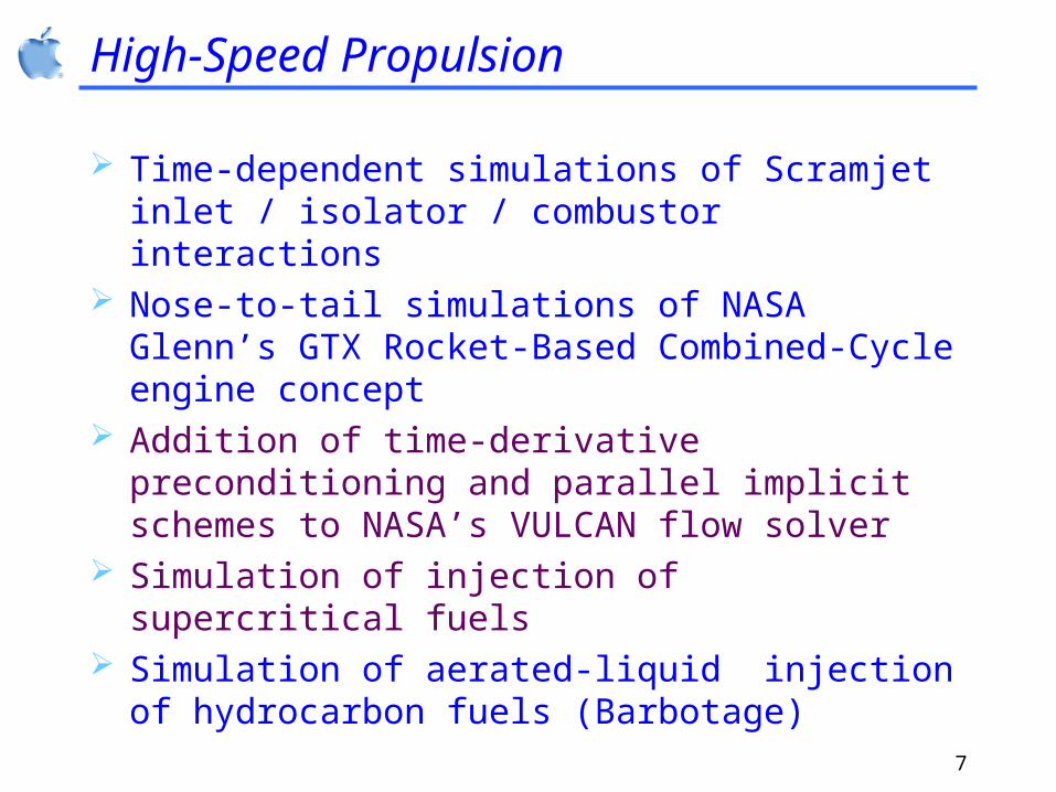
High-Speed Propulsion
Time-dependent simulations of Scramjet inlet / isolator / combustor interactions
Nose-to-tail simulations of NASA Glenn’s GTX Rocket-Based Combined-Cycle engine concept
Addition of time-derivative preconditioning and parallel implicit schemes to NASA’s VULCAN flow solver
Simulation of injection of supercritical fuels Simulation of aerated-liquid injection of hydrocarbon
fuels (Barbotage)

8
Independent Ramjet Stream Cycle in RBCC Engines
Injectors add fuel to the incoming air. Mixing in ramjet stream precedes ignition. Thermal throat is present. Location of thermal throat can be modulated by variations in fuel injection.
Thermal ThroatFlame Front
Rocket exhaust
Fuel injection and premixing

9
Rocket-Based Combined-Cycle Simulations

10
Rocket-Based Combined-Cycle Simulations

11
Rocket-Based Combined-Cycle Simulations: Rocket-shutoff with Nitrogen Purge

12
Aerated-liquid (Barbotage) injection experiments
The Air Force Research Lab (AFRL) aerated-liquid injector is schematically illustrated in Fig. 01;
Rectangular configuration with a dimension of 6.4 mm x 2.0 mm;
A square cross section with dimension, D, of 2.0 mm used for the final discharge passage, L/D=20, converging angle θ=50°;
Water as the test liquid, and nitrogen as the aerating gas.
Fig. 01, Schematic of the injector assembly and internal flow structure

13
Volume fraction contours (GLR = 0.08%)
Bernoulli inflow B.C. for the liquid phase

14
GLR=2.45% Photos and simulations

15
Hybrid LES/RANS Simulation Techniques
General approach: unsteady RANS (Reynolds-Averaged Navier-Stokes) near solid surfaces – LES (large-eddy simulation) in outer part of the boundary layer and in free-shear layers
Transition between RANS / LES based on flow-dependent blending functions based on ratios of turbulence length scales – best results when transition occurs in outer part of log layer
RANS models: k- and Menter’s k-
LES subgrid model: Yoshizawa’s one-equation SGS model
Applications to cavity flameholder configurations, flow behind projectiles, shock / boundary layer interactions

16
Hybrid LES/RANS Simulation Techniques
Instantaneous axial velocity (25 degree compression / expansion corner)

17
Hybrid LES/RANS Simulation Techniques
x', cm
pw/p
-5 0 50.5
1
1.5
2
2.5
3
3.5
4
4.5
5EXPHybrid (k-, F=F3, fine grid)Hybrid (k-, F=F3, coarse grid)RANS (k-)
Wall pressure distributions (25 degree compression/ expansion corner)
u/uey',cm
0
0.1
0.2
0.3
0.4
0.5
0.6
ExpHybrid (k-, F=F3, fine grid)Hybrid (k-, F=F3, coarse grid)RANS (k-)
x' = 1.25 cm 2.35 cm 3.10 cm
1 1 10
Velocity profiles in recovery region (25 degree compression / expansion corner)

18
NIA-Sponsored Work
Primary Goal: to extend earlier work in hybrid LES/RANS simulations to three-dimensional flows characteristic of dual-mode scramjet engines
Year 1 accomplishments
• Addition of generalized multi-block capability to hybrid LES/RANS solver
• Addition of full reactive-flow capability
• Development of better blending functions to shift modeling from unsteady RANS to LES
Test cases underway:
• Investigation of separation-shock unsteadiness in compression-corner interactions
• Simulation of reactive flow downstream of UVA single-ramp, dual-mode injector using hybrid LES/RANS

19
NIA-Sponsored Work: Separation-Shock Unsteadiness
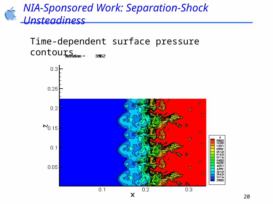
Prediction of response of turbulent boundary layer to shock interaction (representative of high-speed flows within inlet / isolator configurations)
Large-scale, low-frequency unsteadiness of regions of shock-separated flow observed in experiments
Can hybrid LES/RANS methods predict this type of unsteadiness?
20
NIA-Sponsored Work: Separation-Shock Unsteadiness
Time-dependent surface pressure contours

21
NIA-Sponsored Work: Separation-Shock Unsteadiness
Average surface pressure distributions PDF of separation-shock position

22
Leveraging NIA-Sponsored Work
“Hybrid LES/RANS Simulations of Complex Internal Flows with Multiple Shock / Boundary Layer Interactions” Edwards and Hassan; AFOSR; pending
“Database and Model Development for Combined-Cycle Mode Transition” McDaniel, Cresci, Edwards, Goyne, O’Brian, Riggins, Schetz; NASA NGLTP; pending (submitted by NIA)
MURI White Paper on Combined Cycle Engines, Frankel, Edwards,
McDaniel, Goyne, Hanson, Sung, Dutton, Loth; AFOSR; pending

23
Challenges
Demise of North Carolina Supercomputing Center (July 1, 2003) – loss of 720 processor IBM SP-3
Mitigation strategies:
• 32 processor IBM P690 (NCSU)
• 32 processor IBM Bladecenter (NCSU)
• 128 processor IBM Bladecenter (NCSU; under construction; expandable)
• Access to 1024 processor IBM SP-3 at Oak Ridge National Laboratories

24
Simulation of a time-dependent coatings process

25
Pollutant Capture in Circulating Fluidized Beds
Three-phase system: two solids phases, one multi-component gas phase
Sub-models for fine particulate matter agglomeration, sulfur dioxide sorption, mercury capture onto activated carbon
High-resolution LDFSS extension for separated gas-solid flows

26
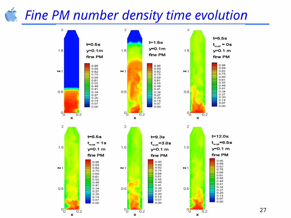
Solids voidage time evolution
27
Fine PM number density time evolution

28
Fine PM flow rates

29
Supercavitating water flow about a projectile

30
New Directions
Atmospheric turbulence modeling and solution-adaptive meteorological simulations
Level-set methods and immersed-boundary algorithms
• Human-induced contaminant transport
• Diesel engine injector simulations
• Two-phase bubble dynamics Hybrid LES/RANS simulations of
• Shock-train propagation
• Ramped-injector flowfields
• Biological systems (lung bronchii, aortic aneurisms)

31
Level-Set / Immersed Boundary Methods: 2-D Simulation of “feet” moving in a box filled with air