Embed Size (px)
Citation preview
1
Control & Automation For
Super Critical Units
K.S. SundaramNTPC, SIPAT
2
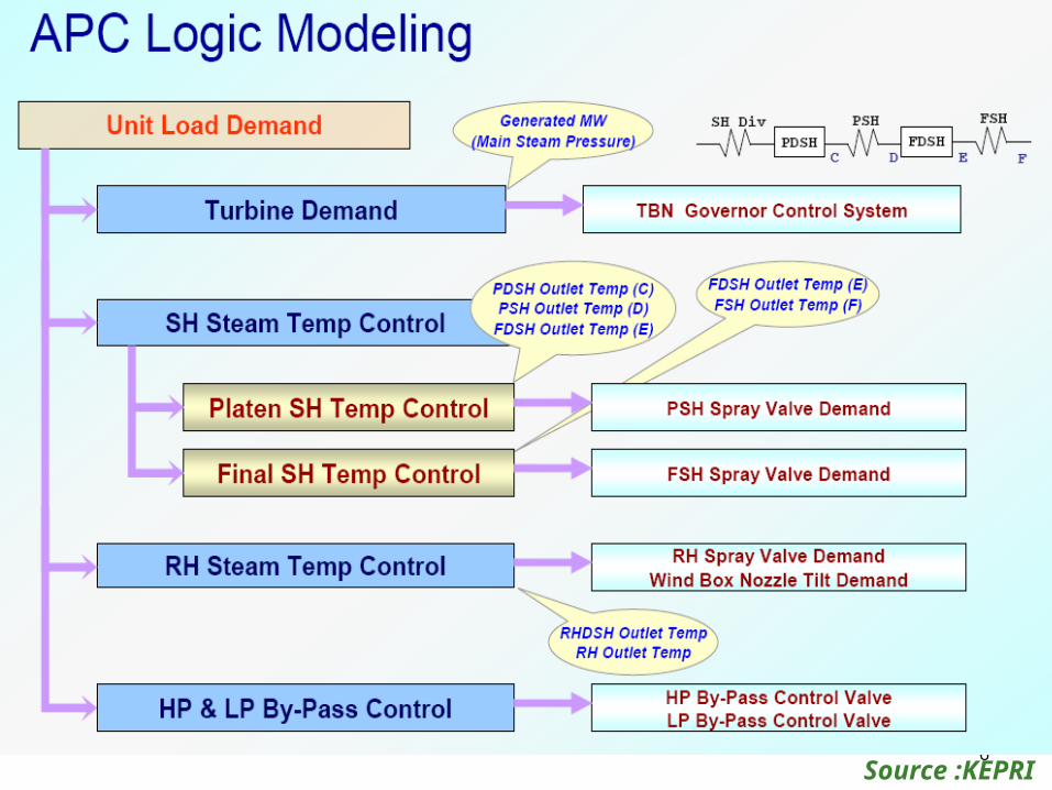
Introduction
• Requirements
• Comparison of Auto loops -Sub Critical Vs Super Critical
• Feed Water Control
• Steam Temperature Control
• Unit Control
• Turbine Control
• Discussions
3
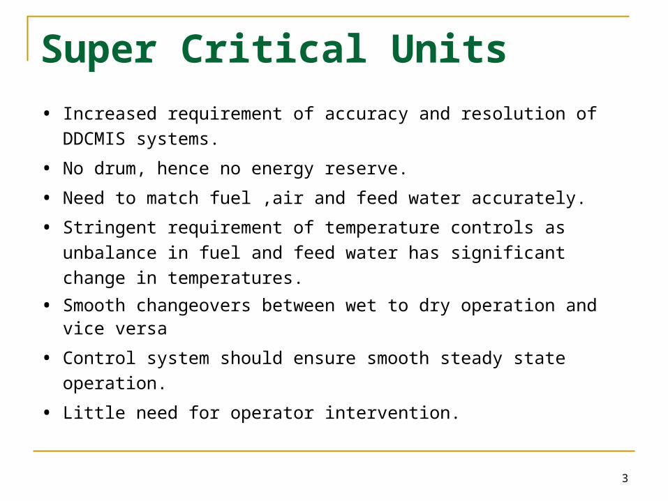
Super Critical Units
• Increased requirement of accuracy and resolution of DDCMIS
systems.
• No drum, hence no energy reserve.
• Need to match fuel ,air and feed water accurately.
• Stringent requirement of temperature controls as unbalance in
fuel and feed water has significant change in temperatures.
• Smooth changeovers between wet to dry operation and vice versa
• Control system should ensure smooth steady state operation.
• Little need for operator intervention.
4Source :KEPRI
5Source :KEPRI
6Source :KEPRI
7
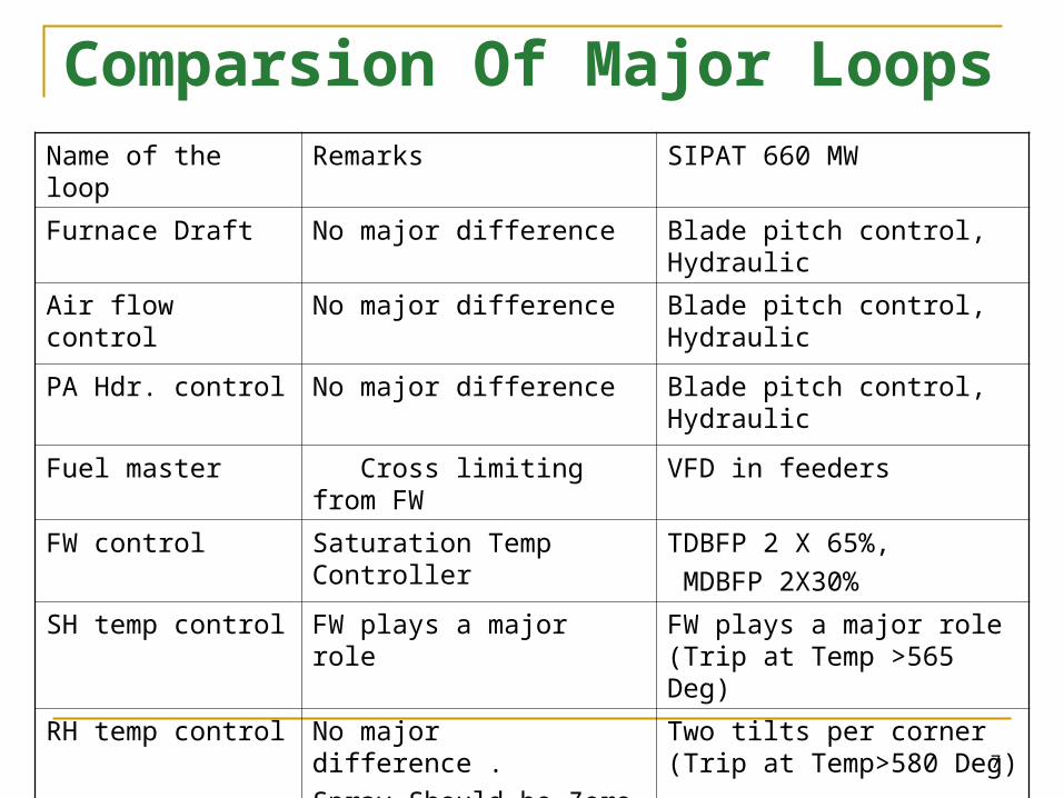
Comparsion Of Major Loops
Name of the loop Remarks SIPAT 660 MW
Furnace Draft No major difference Blade pitch control, Hydraulic
Air flow control No major difference Blade pitch control, Hydraulic
PA Hdr. control No major difference Blade pitch control, Hydraulic
Fuel master Cross limiting from FW VFD in feeders
FW control Saturation Temp Controller TDBFP 2 X 65%,
MDBFP 2X30%
SH temp control FW plays a major role FW plays a major role (Trip at Temp >565 Deg)
RH temp control No major difference .
Spray Should be Zero
Two tilts per corner (Trip at Temp>580 Deg)
8
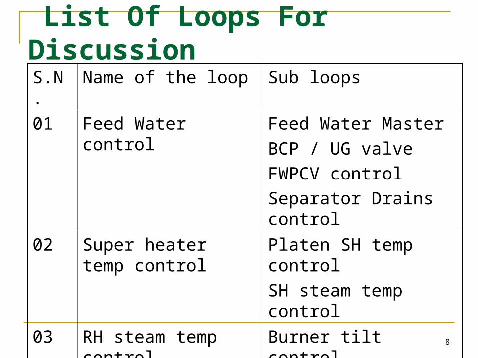
List Of Loops For DiscussionS.N. Name of the loop Sub loops
01 Feed Water control Feed Water Master
BCP / UG valve
FWPCV control
Separator Drains control
02 Super heater temp control
Platen SH temp control
SH steam temp control
03 RH steam temp control
Burner tilt control
Spray valves control
9
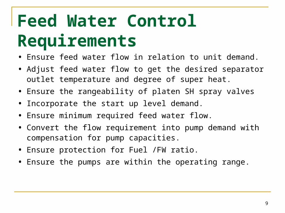
Feed Water Control Requirements• Ensure feed water flow in relation to unit demand.
• Adjust feed water flow to get the desired separator outlet temperature and degree of super heat.
• Ensure the rangeability of platen SH spray valves
• Incorporate the start up level demand.
• Ensure minimum required feed water flow.
• Convert the flow requirement into pump demand with compensation for pump capacities.
• Ensure protection for Fuel /FW ratio.
• Ensure the pumps are within the operating range.
10
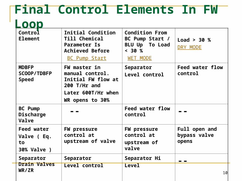
Final Control Elements In FW Loop
Control Element Initial Condition Till Chemical Parameter Is Achieved Before
BC Pump Start
Condition From BC Pump Start / BLU Up To Load < 30 %
WET MODE
Load > 30 %
DRY MODE
MDBFP SCOOP/TDBFP Speed
FW master in manual control. Initial FW flow at 200 T/Hr and
Later 600T/Hr when
WR opens to 30%
Separator
Level control
Feed water flow control
BC Pump Discharge Valve -- Feed water flow
control --
Feed water
Valve ( Eq. to
30% Valve )
FW pressure control at upstream of valve
FW pressure control at
upstream of valve
Full open and bypass valve opens
Separator Drain Valves WR/ZR
Separator
Level control
Separator Hi
Level--
11
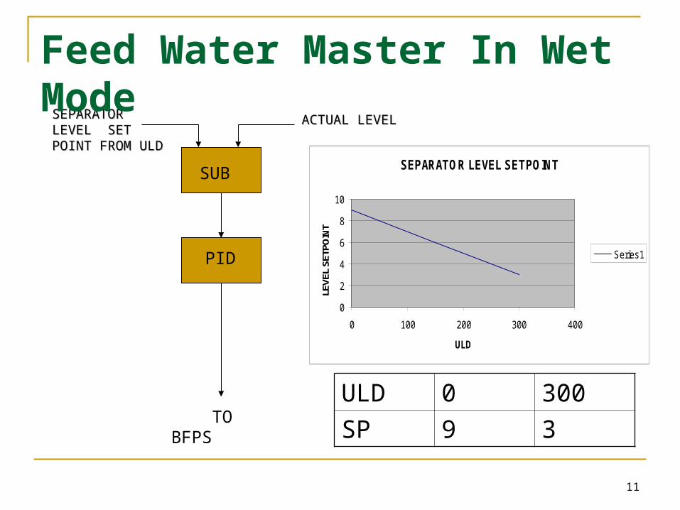
SUB
PID
SEPARATOR SEPARATOR LEVEL SET LEVEL SET POINT FROM POINT FROM ULDULD
ACTUAL LEVELACTUAL LEVEL
TO BFPS
SEPARATOR LEVEL SETPOINT
0
2
4
6
8
10
0 100 200 300 400
ULD
LEVE
L SE
TPO
INT
Series1
ULD 0 300
SP 9 3
Feed Water Master In Wet Mode
12
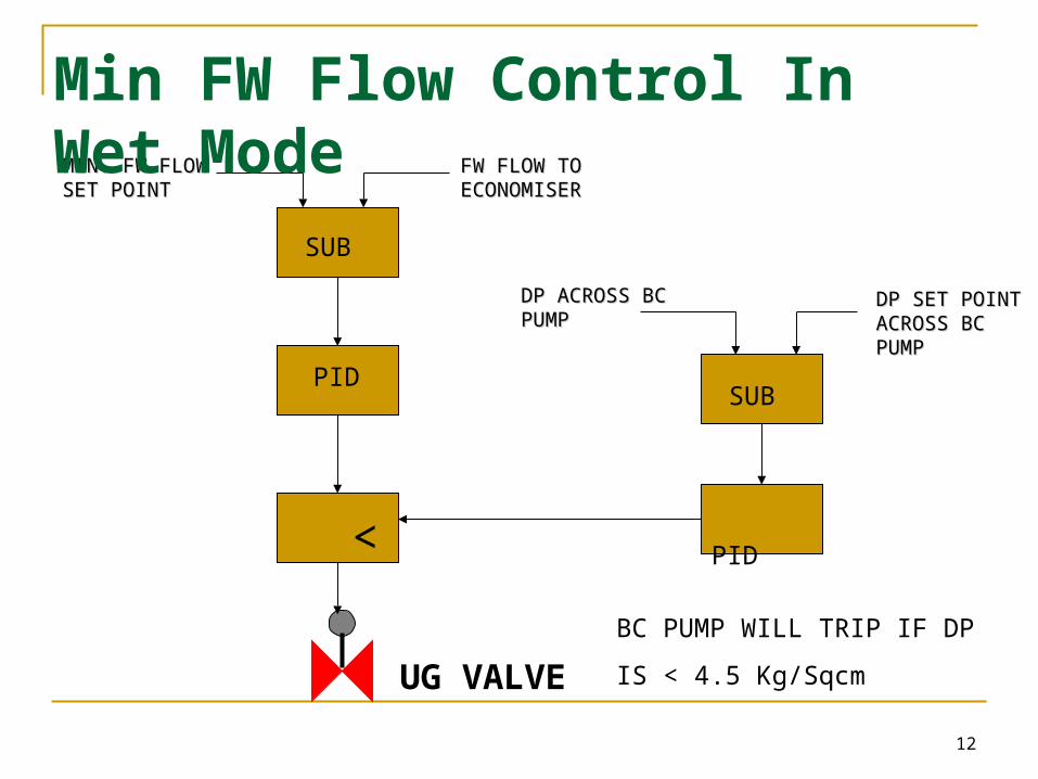
SUB
PID
<
SUB
PID
MIN. FW FLOW MIN. FW FLOW SET POINTSET POINT
FW FLOW TO FW FLOW TO ECONOMISERECONOMISER
DP ACROSS BC DP ACROSS BC PUMPPUMP
DP SET POINT DP SET POINT ACROSS BC ACROSS BC PUMPPUMP
UG VALVE
BC PUMP WILL TRIP IF DP
IS < 4.5 Kg/Sqcm
Min FW Flow Control In Wet Mode
13
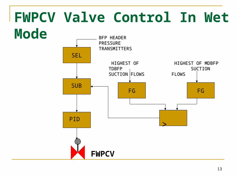
SEL
FGSUB
PID >
BFP HEADER BFP HEADER PRESSURE PRESSURE TRANSMITTERSTRANSMITTERS
FWPCV
FG
HIGHEST OF TDBFP HIGHEST OF TDBFP SUCTION SUCTION FLOWSFLOWS
HIGHEST OF MDBFP HIGHEST OF MDBFP SUCTION FLOWS SUCTION FLOWS
FWPCV Valve Control In Wet Mode
14
F(X)F(X)F(X)F(X)
WR
ZR
MEASURED SEPERATOR LEVELMEASURED SEPERATOR LEVEL
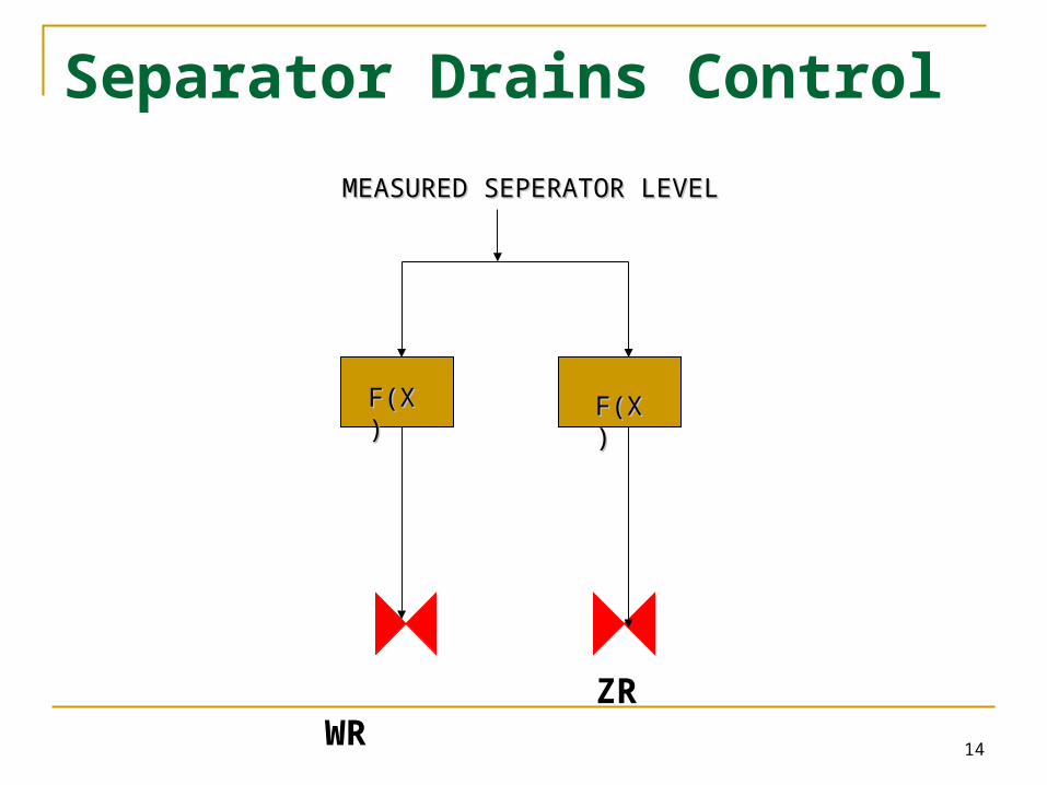
Separator Drains Control
15
• Separator level control by BFPs and FW flow control by UG .Min FW
flow set point from boiler desk. Initial level set point is 9 Mtr. WR and
ZR will act as emergency control for separator level
• If water disappears in separator during wet mode then boiler will trip
on separator level low low – 1.1 Mtr (3 Sec delay)
• Boiler will trip if separator outlet level goes high high in wet mode –
17.7 Mtr
• WR opens at 14.2 Mtr in auto
• ZR opens at 16.2 Mtr in auto
•
Wet Mode Operation
16
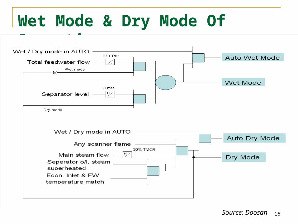
Wet Mode & Dry Mode Of Operation
Source: Doosan
17
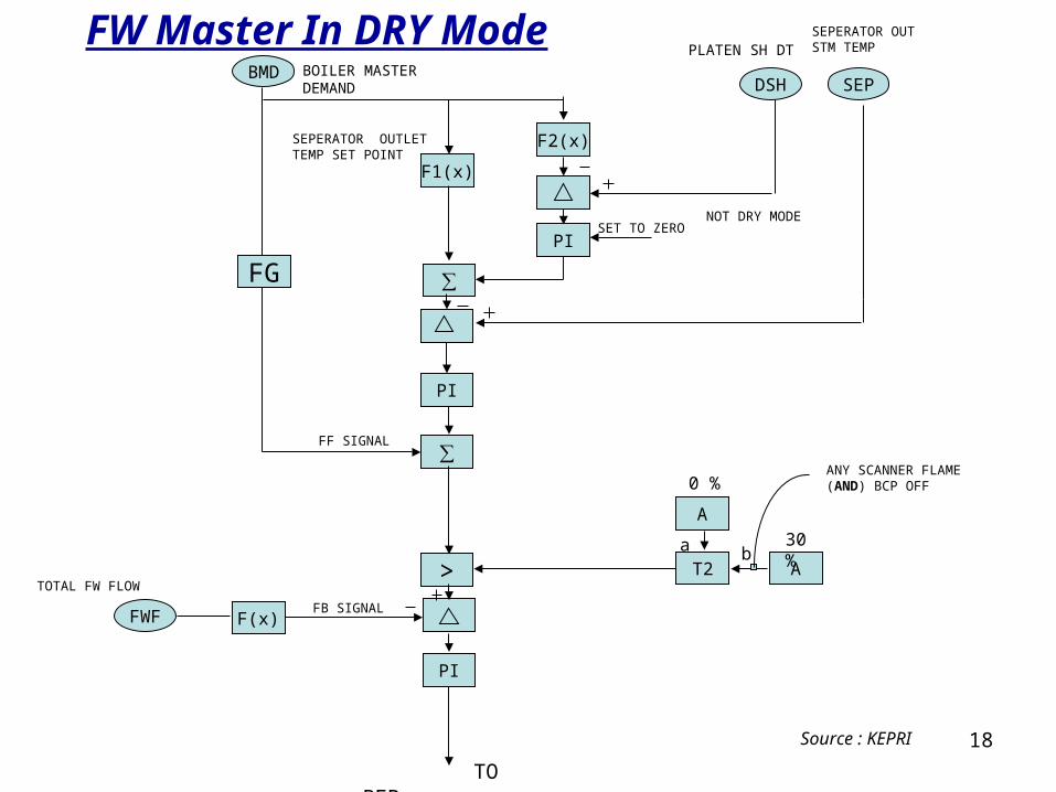
• First controller acts on load dependant average DT across PDSH.
Its output represents the required adjustment to maintain the
steam conditions, flue gas temperatures entering Platen SH so
as to ensure adequate spray platen range.
• Second controller acts on load dependant separator temperature
set point corrected by first controller. The output adjusts feed water
in response to firing system disturbances.
• Minimum set point of 30% for safety is additionally provided.
Feed Water Control In Dry Mode
18
SEPDSH
F2(x)
PI
∑
PI
∑
F1(x)
PI
>
BMD
A
AT2
BOILER MASTER DEMAND
PLATEN SH DTSEPERATOR OUT STM TEMP
SEPERATOR OUTLET TEMP SET POINT
SET TO ZERONOT DRY MODE
ANY SCANNER FLAME (AND) BCP OFF
a b
0 %
30 %
FWF F(x)FB SIGNAL
TOTAL FW FLOW
FF SIGNAL
TO BFPs
FG
FW Master In DRY Mode
Source : KEPRI
19
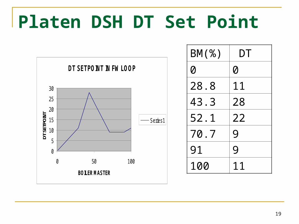
DT SETPOINT IN FW LOOP
0
5
10
15
20
25
30
0 50 100
BOILER MASTER
DT S
ETPO
INT
Series1
BM(%) DT
0 0
28.8 11
43.3 28
52.1 22
70.7 9
91 9
100 11
Platen DSH DT Set Point
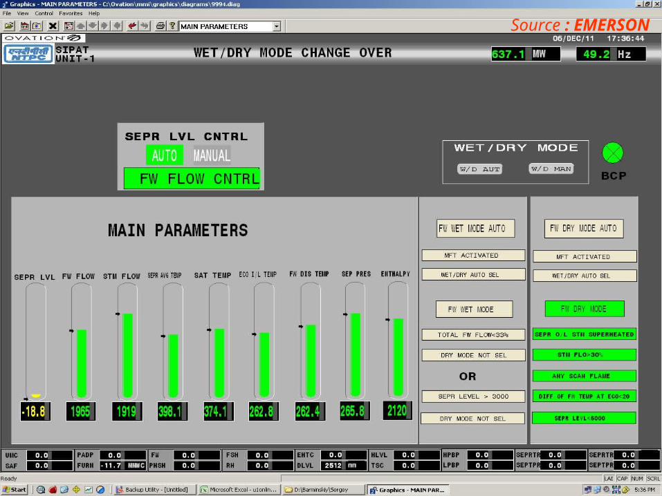
Source : EMERSON
Source : EMERSON
22
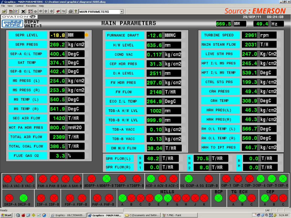
Source : EMERSON
23
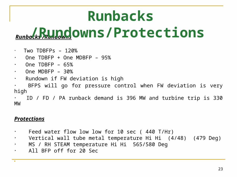
Runbacks /Rundowns
• Two TDBFPs – 120%• One TDBFP + One MDBFP – 95%• One TDBFP – 65%• One MDBFP – 30%• Rundown if FW deviation is high • BFPS will go for pressure control when FW deviation is very high• ID / FD / PA runback demand is 396 MW and turbine trip is 330 MW
Protections
• Feed water flow low low for 10 sec ( 440 T/Hr)• Vertical wall tube metal temperature Hi Hi (4/48) (479 Deg)• MS / RH STEAM temperature Hi Hi 565/580 Deg• All BFP off for 20 Sec
Runbacks /Rundowns/Protections
24
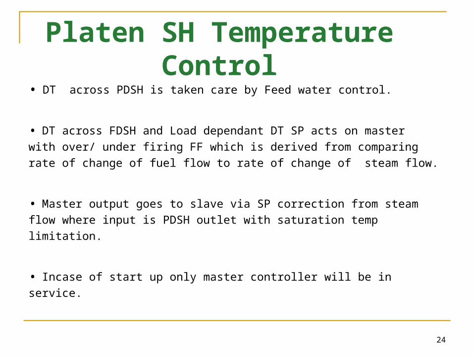
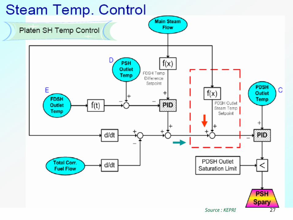
• DT across PDSH is taken care by Feed water control.
• DT across FDSH and Load dependant DT SP acts on master
with over/ under firing FF which is derived from comparing rate of
change of fuel flow to rate of change of steam flow.
• Master output goes to slave via SP correction from steam flow
where input is PDSH outlet with saturation temp limitation.
• Incase of start up only master controller will be in service.
Platen SH Temperature Control
25
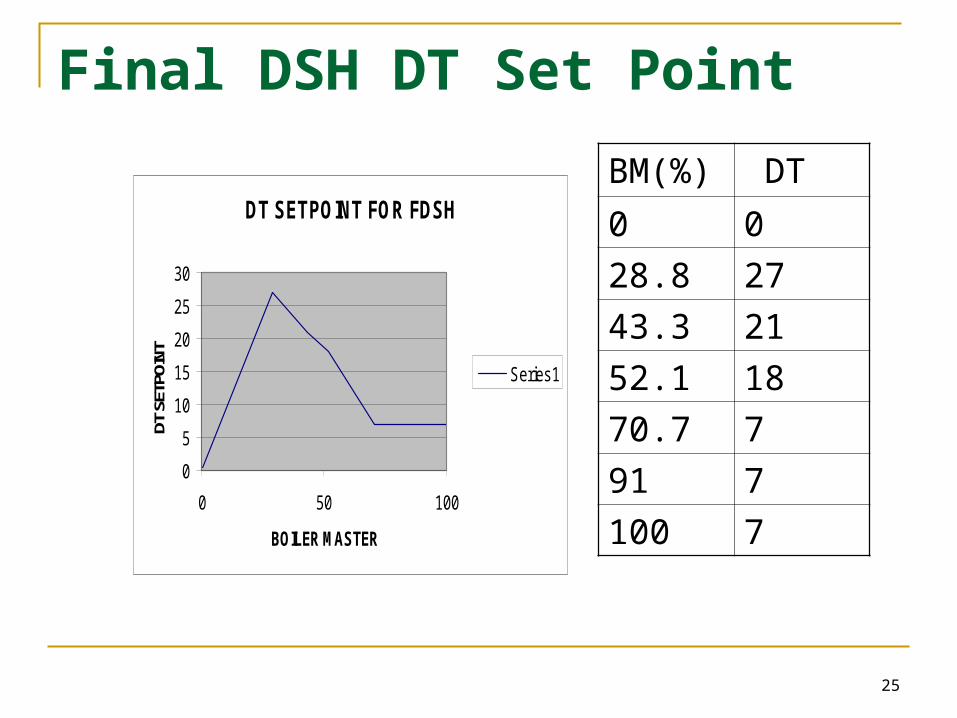
BM(%) DT
0 0
28.8 27
43.3 21
52.1 18
70.7 7
91 7
100 7
DT SETPOINT FOR FDSH
0
5
10
15
20
25
30
0 50 100
BOILER MASTER
DT S
ETPO
INT
Series1
Final DSH DT Set Point
26
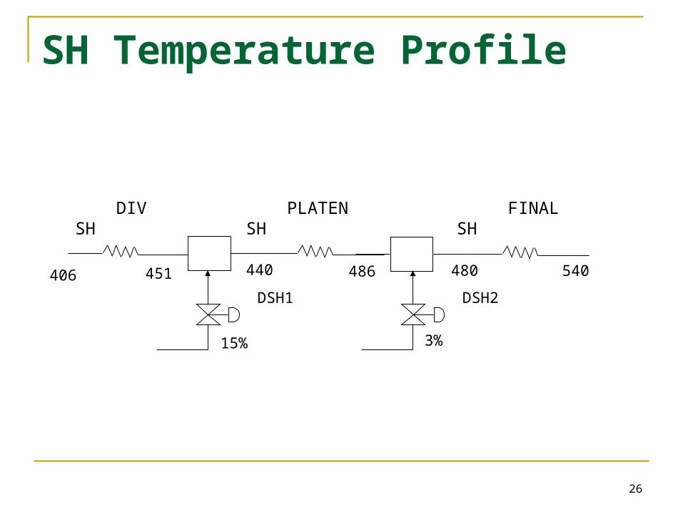
406 451 440 486 480 540
DSH1 DSH2
15% 3%
PLATEN SH FINAL SH DIV SH
SH Temperature Profile
27Source : KEPRI
28
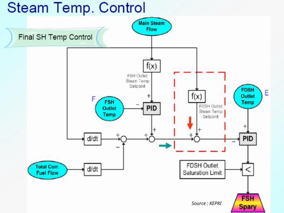
• DT across FDSH is taken care by Platen SH temperature control.
• Final SH O/L temp and Load dependant temp SP acts on master with over/under firing FF which is derived from comparing rate of change of fuel flow to rate of change of steam flow.
• Master output goes to slave via SP correction from steam flow where input is FDSH outlet with saturation temp limitation.
• Incase of start up only master controller will be in service.
Final SH Temperature Control
29Source : KEPRI
30
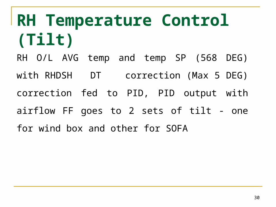
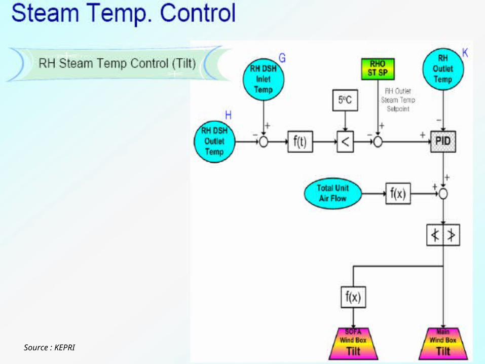
RH Temperature Control (Tilt)RH O/L AVG temp and temp SP (568 DEG) with
RHDSH DT correction (Max 5 DEG) correction fed to
PID, PID output with airflow FF goes to 2 sets of tilt - one
for wind box and other for SOFA
31Source : KEPRI
32
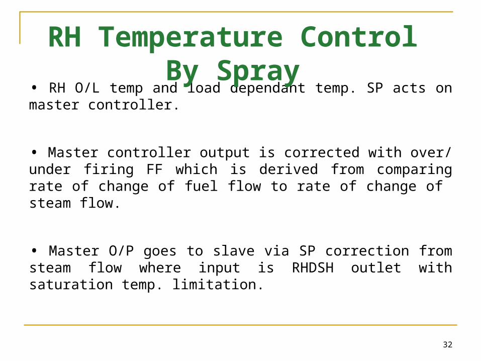
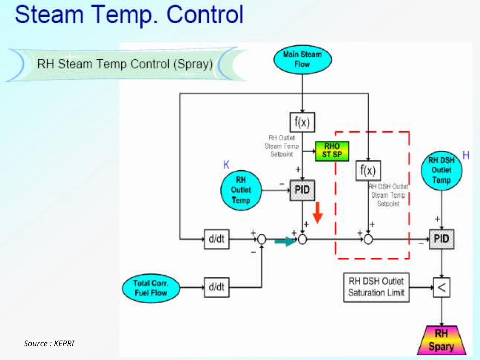
• RH O/L temp and load dependant temp. SP acts on master controller.
• Master controller output is corrected with over/ under firing FF which is derived from comparing rate of change of fuel flow to rate of change of steam flow.
• Master O/P goes to slave via SP correction from steam flow where input is RHDSH outlet with saturation temp. limitation.
RH Temperature Control By Spray
33Source : KEPRI
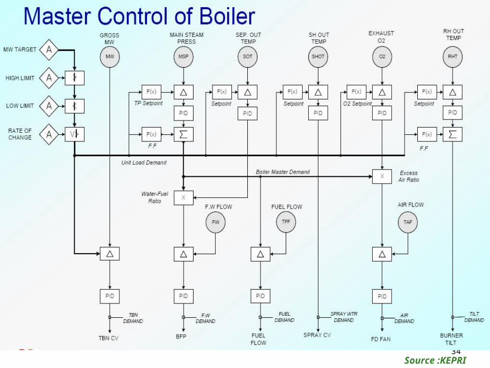
34Source :KEPRI
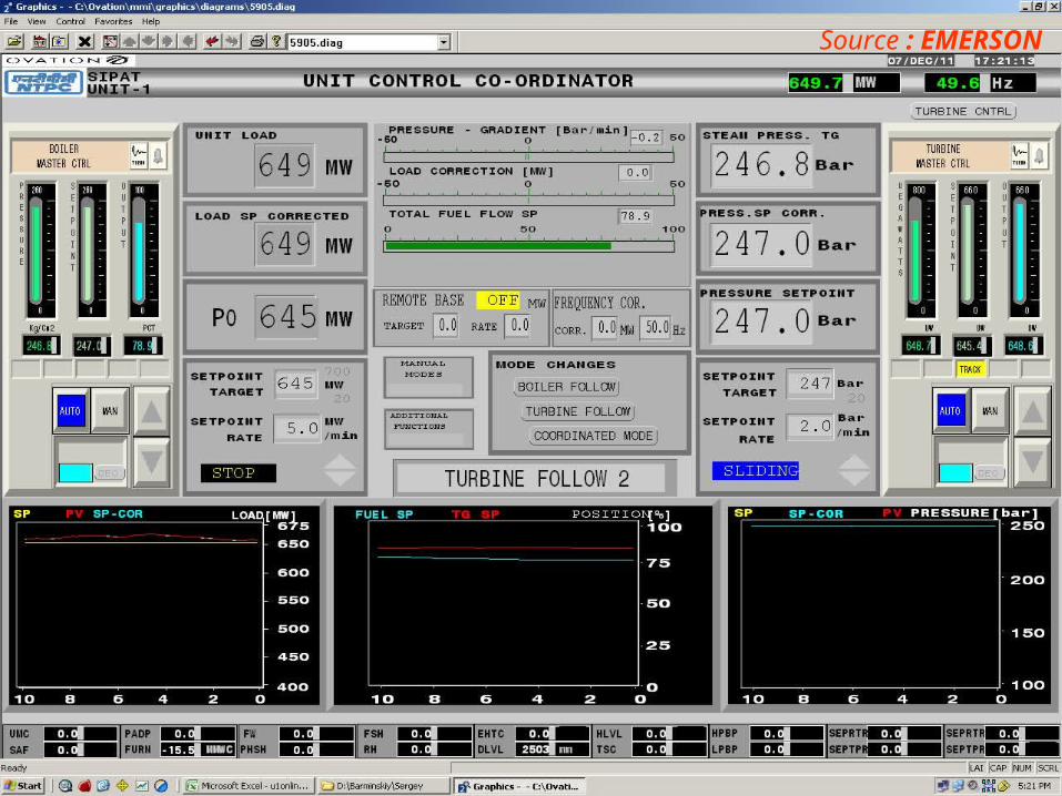
Source : EMERSON
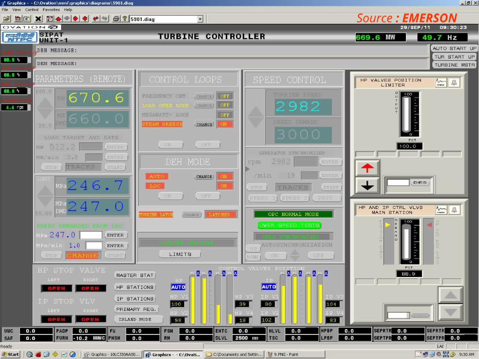
Source : EMERSON
37
Turbine Control
• Speed Loop- Till synchronization (IP Rolling)
• IP is Throttle governing & HP is Nozzle governing
• Open load loop till HP is charged
• Pressure Control when HP is charged
• Sliding Pressure Operation from 90 to 247 Kg/sqcm
• Achieve full load & put on CMC
Salient Features:
• Individual EHC for individual valves
• No Hydraulic back up operation
38
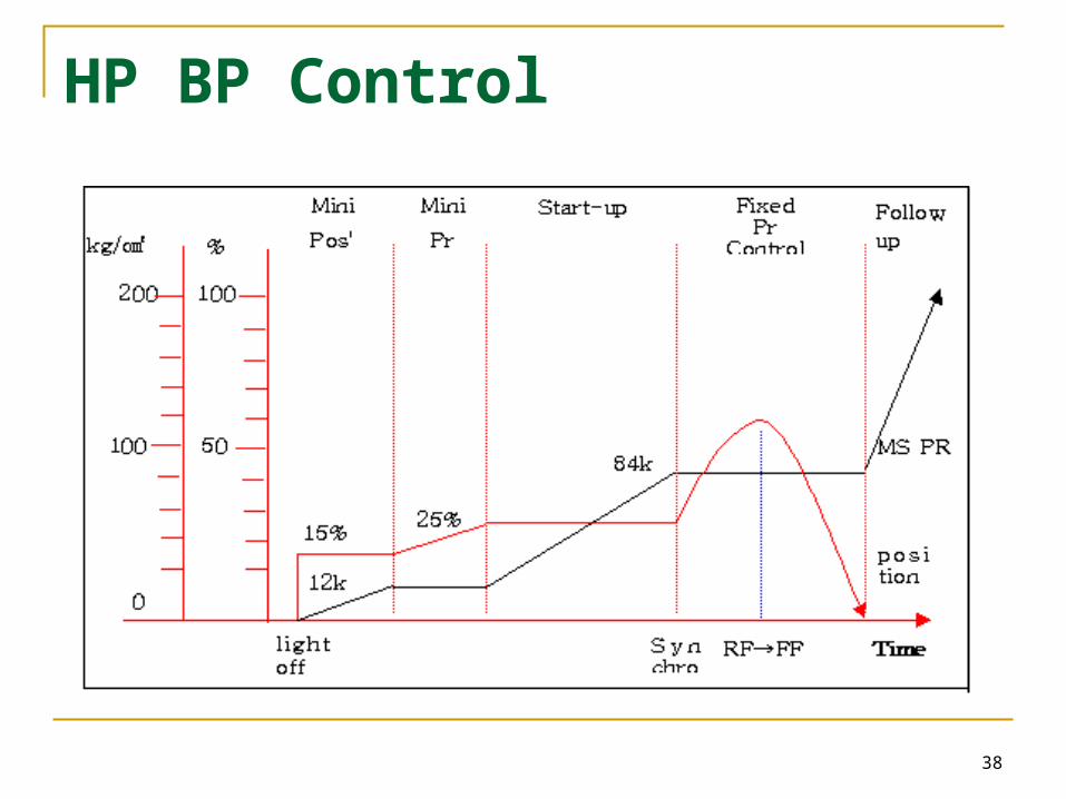
HP BP Control
39
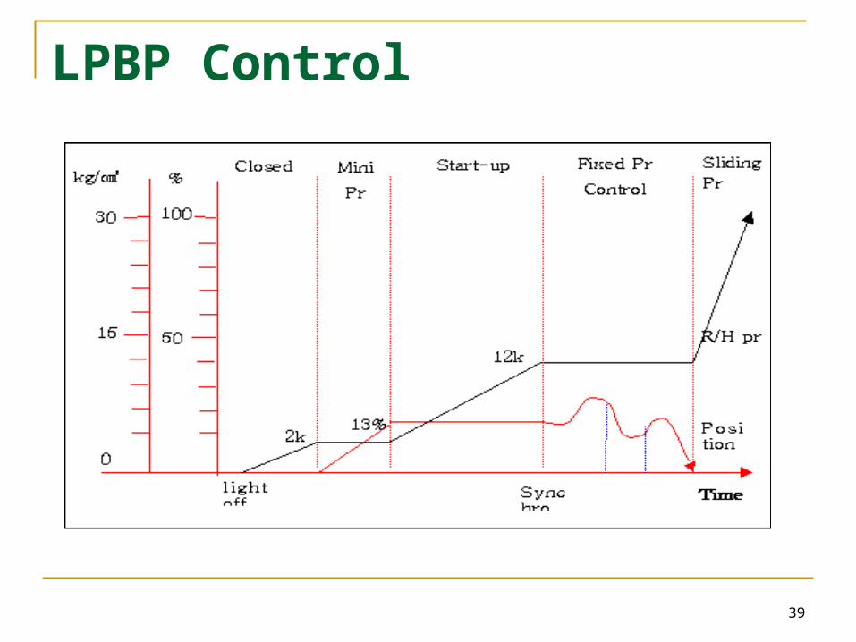
LPBP Control
40
• KEPRI logics
• EMERSON Logics
References

41
THANK YOU
42
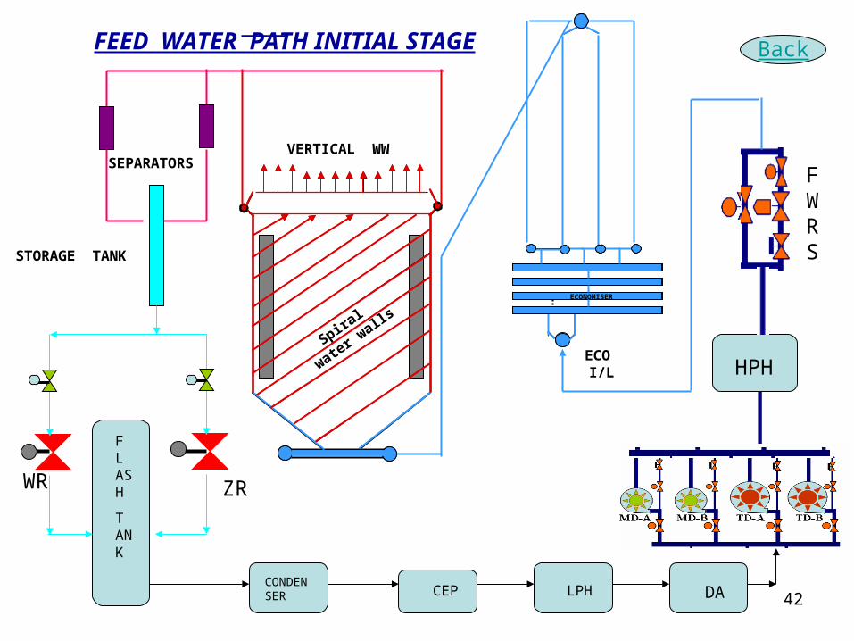
HPHECO I/L
ECONOMISER
Spiral w
ater
walls
VERTICAL WW
F L ASH
T ANK
WR
ZR
SEPARATORS
STORAGE TANK
CONDENSER CEP LPH DA
FWRS
Back
FEED WATER PATH INITIAL STAGE
43
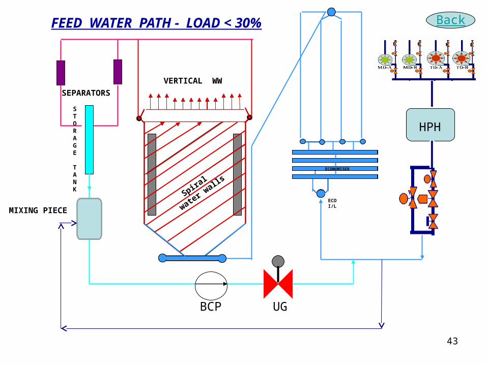
HPH
ECO I/L
ECONOMISER
Spiral w
ater
walls
VERTICAL WW
STORAGE TANK
SEPARATORS
MIXING PIECE
BCP UG
BackFEED WATER PATH - LOAD < 30%
44
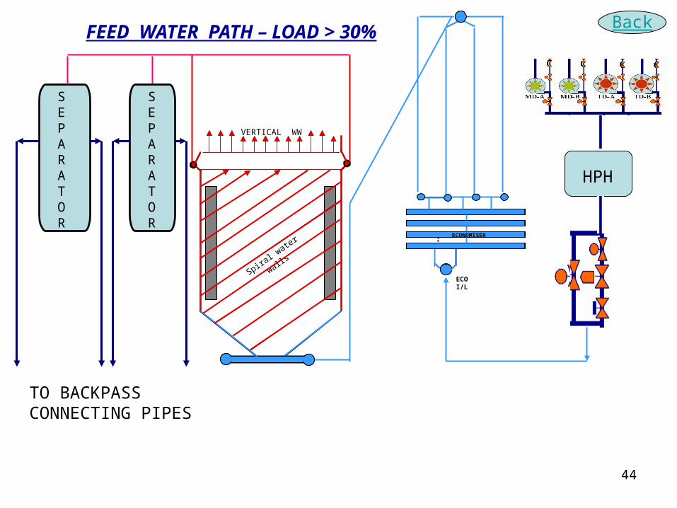
HPH
ECO I/L
ECONOMISER
Spiral w
ater walls
VERTICAL WW
TO BACKPASS CONNECTING PIPES
SEPARATOR
SEPARATOR
FEED WATER PATH – LOAD > 30% Back
45
46
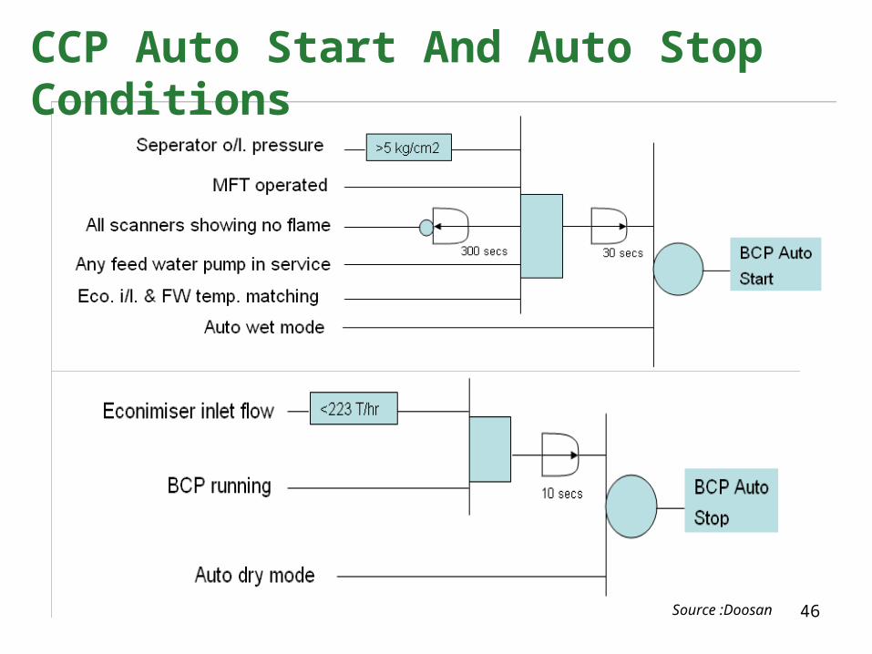
CCP Auto Start And Auto Stop Conditions
Source :Doosan