Embed Size (px)
Citation preview

Operating instructions
Hydraulic cushioning cylinder
Type YZL- 80 YZL-160 YZL-250
Conditions regarding the use of Festo equipment. This is important for reasons of safety 1 . lt 1s most important that only properly 1nstructed and qualified personel uses this equipment.
2. This equipment should only be used within the limits detailed in the technical specification. Strict observance of the technical specification should be ensured at all times.
3. Correctly prepared compressed air should be used at all times. When installing the equipment and thereafter, the Customer shal l ensure that the environmental conditions at the place of use are taken into consideration.
4. lf the equipment 1s incorporated in a system or used within safety devices or ci rcuits, the Customer shall ensure that national and local safety laws and regulations are observed.
5. Should you require further information , please contact your local Festo office.
These instructions are important. Please keep them in a safe place.
224 284 Bedienungsanleitung
Ölbremszylinder
Typ YZL- 80 YZL-160 YZL-250
Was ist beim Einsatz von Festo Elementen zu beachten?
Die Einhaltung der jeweils angegebenen Grenzwerte für Drücke, Spannungen, Temperaturen und die Beachtung von Hinweisen ist Voraussetzung für die ordnungsgemäße Funktion und daher vom Anwender unbedingt zu gewährleisten.
Es ist auf den Betrieb mit ordnungsgemäß aufbereiteter Druckluft ohne aggressive Medien zu achten. Außerdem sind die jeweiligen Umweltbedingungen am Einsatzort zu berücksichtigen.
Bei Anwendungen von Festo Elementen im Sicherheitsbereich sind stets auch die jeweiligen Vorschriften der Berufsgenossenschaft und des Technischen ÜberwachungsVereins bzw. die entsprechenden nationalen Bestimmungen zu beachten.
Die VDE-Bestimmungen bzw. die entsprechenden nationalen Bestimmungen über den Umgang mit elektrischen Geräten sind einzuhalten.
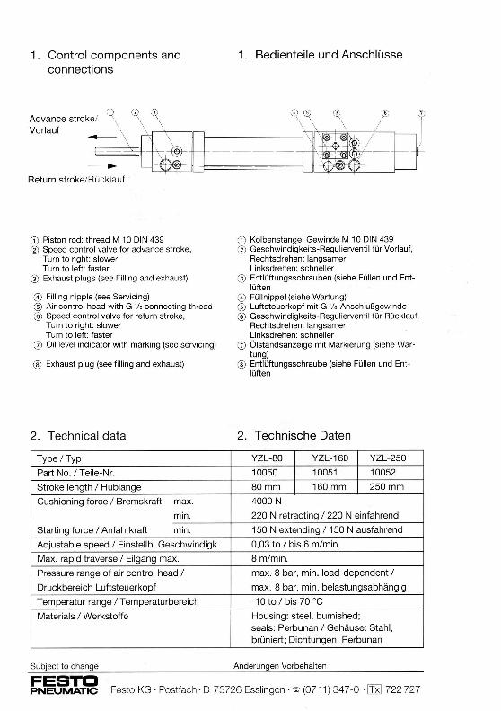
1 . Control components and connections
1 . Bedienteile und Anschlüsse
~ ~'J ~:::;'"'°'~: =a---------= --8 Return stroke/Rücklauf
CD Piston rod: thread M 10 DIN 439 0 Speed control valve for advance strake,
Turn to right: slower Turn to left: faster
@ Exhaust plugs (see Filling and exhaust)
@ Filling nipple (see Servicing) ® Air control head with G '/a connecting thread ® Speed control valve for return strake,
Turn to right: slower Turn to left: faster
0 Oil level indicator with marking (see servicing)
® Exhaust plug (see filling and exhaust)
2. Technical data
Type/Typ
Part No./ Teile-Nr.
Strake length /Hublänge
Cushioning force / Bremskraft max.
min.
Starling force /Anfahrkraft min.
Adjustable speed / Einstellb. Geschwindigk.
Max. rapid traverse / Eilgang max.
Pressure range of air control head /
Druckbereich Luftsteuerkopf
Temperatur range /Temperaturbereich
Materials/ Werkstoffe
Subject to change
CD Kolbenstange: Gewinde M 10 DIN 439 0 Geschwindigkeits-Regulierventil für Vorlauf,
Rechtsdrehen: langsamer Linksdrehen: schneller
@ Entlüftungsschrauben (siehe Füllen und Ent-lüften
@ Füllnippel (siehe Wartung) ® Luftsteuerkopf mit G '/a-Anschlußgewinde ® Geschwindigkeits-Regulierventil für Rücklauf,
Rechtsdrehen: langsamer Linksdrehen: schrneller
0 Ölstandsanzeige mit Markierung (siehe Wartung)
® Entlüftungsschraube (siehe Füllen und Entlüften
2. Technische Daten
YZL-80 YZL-160 YZL-250
10050 10051 10052
80mm 160 mm 250mm
4000 N
220 N retracting / 220 N einfahrend
150 N extending / 150 N ausfahrend
0,03 to I bis 6 m/min.
8 m/min.
max. 8 bar, min. load-dependent /
max. 8 bar, min. belastungsabhängig
- 1 O to / bis 70 °C
Housing: steel, burnished; seals: Perbunan / Gehäuse: Stahl, brüniert; Dichtungen: Perbunan
Änderungen Vorbehalten
FESTD PNEUMATIC Festo KG · Postfach · D-73726 Esslingen · lllr (07 11 ) 34 7 -0 ·[Tu] 722 727

3. Servicing
Leaks can occur in the closed oil circuit during a period of operation.
For this reason , the oil level must be checked regulary (mounthly).
Topping-up the hydraulic cushioning cylinder with oil.
1. Advance piston rod.
2. Using oil gun type YD insert into the filling nipple until the second line mark on the oil level indicator is tlush with the housing.
Oil level indicator (j).
Top-up necessary Nachfüllung nötig
Note
Do not overfill, since otherwise it will not be possible to execute the return stroke (retraction of the piston rod) completely.
lf the oil level is not carefully monitored , there is danger of air infiltrating the hydraulic cushioning cylinder.
Signs of air in the hydraulic cushioning cylinder:
• The piston rod travels unbraked for part of the advance and return stroke.
• The piston rod continues to move quickly for a briet period after the rapid traverse has been switched oft.
• The piston rod runs jerkily.
• The oil level indicator (j) is flush.
In these circumstances the hydraulic cushioning cylinder must be completely refilled and exhausted.
Exhausting the hydraulic cushioning cylinder:
3. Wartung
Es können während des Arbeitseinsatzes im geschlossenen Ölkreislauf Leckverluste auftreten.
Deshalb muß der Ölstand regelmäßig (monatlich) kontrolliert werden.
Öl nachfüllen am Ölbremszylinder.
1. Kolbenstange ausfahren.
2. Mit Ölpresse Typ YD in den Füllnippel Öl pressen, bis die zweite Strichmarke der Ölstandsanzeige mit dem Gehäuse bündig ist.
Ölstandsanzeige (j) .
Oil level correct Richtig nachgefüllt
Hinweis
Nicht überfüllen, da sonst der Rücklauf (Kolbenstange einfahren) nicht vollständig ausgeführt werden kann.
Wird der Ölstand nicht sorgfältig überwacht, besteht die Gefahr, daß Luft in den Ölbremszylinder eindringt.
Anzeichen für Luft im Ölbremszylinder:
• Kolbenstange bewegt sich teilweise ungebremst im Vor- oder Rücklauf.
• Die Kolbenstange bewegt sich nach Abschaltung des Eilgangs noch kurzzeitig schnell weiter.
• Die Kolbenstange läuft ruckweise.
• Der Ölstandsanzeiger (j) ist bündig.
Dann muß der Ölbremszylinder komplett neu gefüllt und entlüftet werden .
Entlüften des Ölbremszylinders:
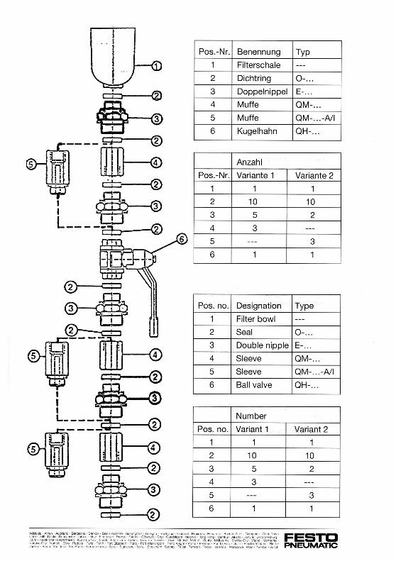
Pos.-Nr. Benennung Typ
1 Filterschale ---
2 Dichtring 0- ...
3 Doppelnippel E- ...
4 Muffe QM-...
5 Muffe QM- ... -NI
6 Kugelhahn QH- ...
Anzahl
Pos.-Nr. Variante 1 Variante 2
1 1 1
2 10 10
3 5 2
4 3 ---
5 --- 3
6 1 1
Pos. no. Designation Type
1 Filter bowl ---
2 Seal 0- .. .
3 Double nipple E- .. .
4 Sleeve QM- .. .
5 Sleeve QM- ... -NI
6 Ball valve OH- .. .
Number
Pos. no. Variant 1 Variant 2
1 1 1
2 10 10
3 5 2
4 3 ---
5 --- 3
6 1 1
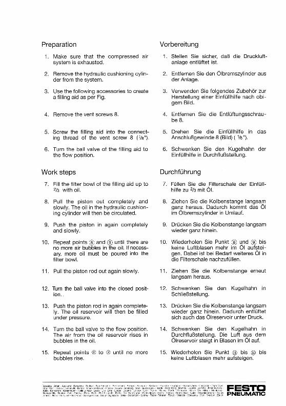
Preparation
1. Make sure that the compressed air system is exhausted.
2. Remove the hydraulic cushioning cylinder from the system.
3. Use the following accessories to create a filling aid as per Fig .
4. Remove the vent screws 8.
5. Screw the filling aid into the connecting thread of the vent screw 8 ( 1/a").
6. Turn the ball valve of the filling aid to the flow position.
Work steps
7. Fill the filter bowl of the filling aid up to 2/3 with oil.
8. Pull the piston out completely and slowly. The oil in the hydraulic cushioning cylinder will then be circulated.
9. Push the piston in again completely and slowly.
10. Repeat points ® and ® until there are no more air bubbles in the oil. lf necessary, more oil must be poured into the filter bowl.
11 . Pull the piston rod out again slowly.
12. Turn the ball valve into the closed position . .
13. Push the piston rod in again completely. The oil reservoir will then be filled under pressure.
14. Turn the ball valve to the flow position. The air from the oil reservoir rises in bubbles in the oil.
15. Repeat points ® to ® until no more bubbles rise.
Vorbereitung
1. Stellen Sie sicher, daß die Druckluftanlage entlüftet ist.
2. Entfernen Sie den Ölbremszylinder aus der Anlage.
3. Verwenden Sie folgendes Zubehör zur Herstellung einer Einfüllhilfe nach obigem Bild.
4. Entfernen Sie die Entlüftungsschraube 8.
5. Drehen Sie die Einfüllhilfe in das Anschlußgewinde 8 (Bild) ( 1/a ").
6. Schwenken Sie den Kugelhahn der Einfüllhilfe in Durchflußstellung.
Durchführung
7. Füllen Sie die Filterschale der Einfüllhilfe zu 2/3 mit Öl.
8. Ziehen Sie die Kolbenstange langsam ganz heraus. Dadurch kommt das Öl im Ölbremszylinder in Umlauf.
9. Drücken Sie die Kolbenstange langsam wieder ganz hinein.
10. Wiederholen Sie Punkt ® u.nd ® bis keine Luftblasen mehr im 01 aufsteigen. Dabei ist bei Bedarf weiteres Öl in die Filterschale nachzufüllen.
11 . Ziehen Sie die Kolbenstange erneut langsam heraus.
12. Schwenken Sie den Kugelhahn in Schließstellung.
13. Drücken Sie die Kolbenstange langsam wieder ganz hinein. Dadurch entlüftet sich auch das Ölreservoir unter Druck.
14. Schwenken Sie den Kugelhahn in Durchflußstellung. Die Luft aus dem Ölreservoir steigt in Blasen im Öl auf.
15. Wiederholen Sie Punkt @ bis @ bis keine Luftblasen mehr aufsteigen.

Concluding work
16. Pull the piston rod out again completely.
17. Turn the ball valve to the closed position. The residual oil column in the filling aid between the ball valve and the hydraulic cushioning cylinder remains.
18. When unscrewing the filling aid from the hydraulic cushioning cylinder, use an absorbent cloth for collecting the residual oil.
19. Screw in the vent screw (8) again. The filling procedure is then completed. The hydraulic cushioning cylinder then receives only the minimum amount of oil.
20. Fill the hydraulic cushioning cylinder with oil as described under Chapter 3. "Maintenance," Selection "Refil ling oil." The oil reservoir will then be filled again.
4. Accessories
For Festo hydraulic cushioning cylinders the following oil is recommended:
Suitable oils I Geeignete Ölsorten
Festo Spezial I Festo Spezialöl Type I Typ OFSB-1 / Part No./ Teile-Nr.207873
Shell Hydrol D0-46
• Oil gun, type YD, order code 2212.
Nachbearbeitung
16. Ziehen Sie die Kolbenstange wieder ganz heraus.
17. Schwenken Sie den Kugelhahn in Schließstellung. Die Restölsäule in der Einfüllhilfe zwischen Kugelhahn und Ölbremszylinder bleibt bestehen.
18. Beim Herausdrehen der Einfüllhilfe aus dem Ölbremszylinders verwenden Sie ein saugfähiges Vlies zum Aufsaugen des Restöls.
19. Drehen Sie die Entlüftungsschraube (8) wieder ein. Damit ist der Füllvorgang beendet. Der Ölbremszylinder enthält jedoch nur doch die Minimalmenge an Öl.
20. Füllen Sie den Ölbremszylinder mit Öl wie unter Kapitel „3 . Wartung", Abschnitt „Öl nachfüllen", beschrieben. Dadurch wird das Ölreservoir wieder gefüllt.
4. Zubehör
Für Festo Ölbremszylinder wird folgendes Öl empfohlen:
Viscosi1/i at 40° C / Viskosität bei 40° C 46 mm /s (= cSt)
As per I nach ISO 3448 ISO VG 46
e Ölpresse, Typ YD, Bestellnummer 2212.
Subject to change Änderungen Vorbehalten
FESTD PNEUMATIC Festo KG · Postfach · D-73726 Esslingen · 'ili' (0711) 34 7-0 · lm 722 727