Embed Size (px)
Citation preview

1Copyright © 2012, Elsevier Inc. All rights Reserved
Chapter 2
Computer Networks, 5th Edition
Getting Connected

2Copyright © 2012, Elsevier Inc. All rights Reserved
Chapter 2
FIGURE 2.1 An end-user’s view of the Internet.

3Copyright © 2012, Elsevier Inc. All rights Reserved
Chapter 2
FIGURE 2.2 Electromagnetic spectrum.

4Copyright © 2012, Elsevier Inc. All rights Reserved
Chapter 2
FIGURE 2.3 Signals travel between signalling components; bits flow between adaptors.

5Copyright © 2012, Elsevier Inc. All rights Reserved
Chapter 2
FIGURE 2.4 NRZ encoding of a bit stream.

6Copyright © 2012, Elsevier Inc. All rights Reserved
Chapter 2
FIGURE 2.5 Different encoding strategies.

7Copyright © 2012, Elsevier Inc. All rights Reserved
Chapter 2
FIGURE 2.6 Bits flow between adaptors, frames between hosts.

8Copyright © 2012, Elsevier Inc. All rights Reserved
Chapter 2
FIGURE 2.7 BISYNC frame format.

9Copyright © 2012, Elsevier Inc. All rights Reserved
Chapter 2
FIGURE 2.8 PPP frame format.

10Copyright © 2012, Elsevier Inc. All rights Reserved
Chapter 2
FIGURE 2.9 DDCMP frame format.

11Copyright © 2012, Elsevier Inc. All rights Reserved
Chapter 2
FIGURE 2.10 HDLC frame format.

12Copyright © 2012, Elsevier Inc. All rights Reserved
Chapter 2
FIGURE 2.11 A SONET STS-1 frame.

13Copyright © 2012, Elsevier Inc. All rights Reserved
Chapter 2
FIGURE 2.12 Three STS-1 frames multiplexed onto one STS-3c frame.

14Copyright © 2012, Elsevier Inc. All rights Reserved
Chapter 2
FIGURE 2.13 SONET frames out of phase.
15Copyright © 2012, Elsevier Inc. All rights Reserved
Chapter 2
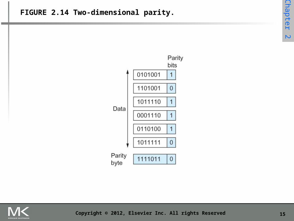
FIGURE 2.14 Two-dimensional parity.

16Copyright © 2012, Elsevier Inc. All rights Reserved
Chapter 2
FIGURE 2.15 CRC calculation using polynomial long division.

17Copyright © 2012, Elsevier Inc. All rights Reserved
Chapter 2
FIGURE 2.16 CRC calculation using shift register.
18Copyright © 2012, Elsevier Inc. All rights Reserved
Chapter 2
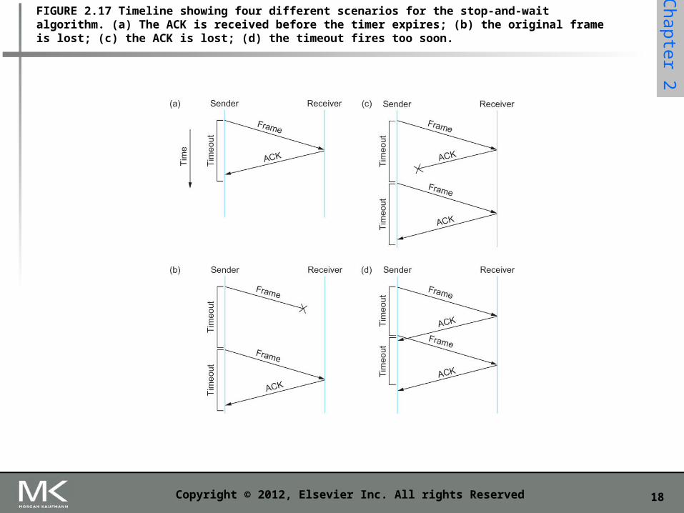
FIGURE 2.17 Timeline showing four different scenarios for the stop-and-wait algorithm. (a) The ACK is received before the timer expires; (b) the original frame is lost; (c) the ACK is lost; (d) the timeout fires too soon.

19Copyright © 2012, Elsevier Inc. All rights Reserved
Chapter 2
FIGURE 2.18 Timeline for stop-and-wait with 1-bit sequence number.

20Copyright © 2012, Elsevier Inc. All rights Reserved
Chapter 2
FIGURE 2.19 Timeline for the sliding window algorithm.

21Copyright © 2012, Elsevier Inc. All rights Reserved
Chapter 2
FIGURE 2.20 Sliding window on sender.
22Copyright © 2012, Elsevier Inc. All rights Reserved
Chapter 2
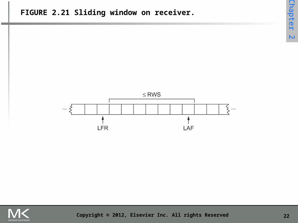
FIGURE 2.21 Sliding window on receiver.
23Copyright © 2012, Elsevier Inc. All rights Reserved
Chapter 2
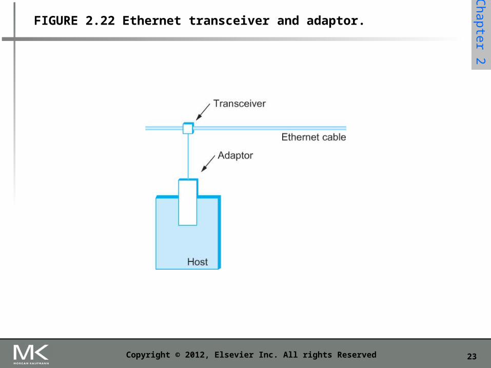
FIGURE 2.22 Ethernet transceiver and adaptor.

24Copyright © 2012, Elsevier Inc. All rights Reserved
Chapter 2
FIGURE 2.23 Ethernet repeater.

25Copyright © 2012, Elsevier Inc. All rights Reserved
Chapter 2
FIGURE 2.24 Ethernet hub.

26Copyright © 2012, Elsevier Inc. All rights Reserved
Chapter 2
FIGURE 2.25 Ethernet frame format.

27Copyright © 2012, Elsevier Inc. All rights Reserved
Chapter 2
FIGURE 2.26 Worst-case scenario: (a) A sends a frame at time t; (b) A’s frame arrives at B at time t + d; (c) B begins transmitting at time t + d and collides with A’s frame; (d) B’s runt (32-bit) frame arrives at A at time t + 2d.

28Copyright © 2012, Elsevier Inc. All rights Reserved
Chapter 2
FIGURE 2.27 Example 4-bit chipping sequence.

29Copyright © 2012, Elsevier Inc. All rights Reserved
Chapter 2
FIGURE 2.28 A wireless network using a base station.

30Copyright © 2012, Elsevier Inc. All rights Reserved
Chapter 2
FIGURE 2.29 A wireless ad hoc or mesh network.
31Copyright © 2012, Elsevier Inc. All rights Reserved
Chapter 2
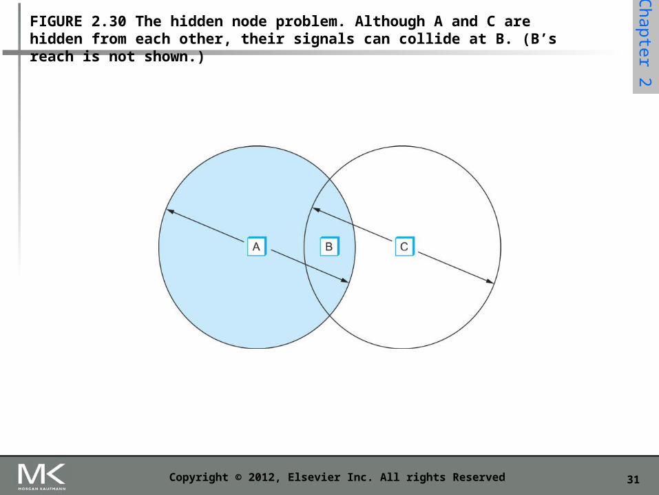
FIGURE 2.30 The hidden node problem. Although A and C are hidden from each other, their signals can collide at B. (B’s reach is not shown.)
32Copyright © 2012, Elsevier Inc. All rights Reserved
Chapter 2
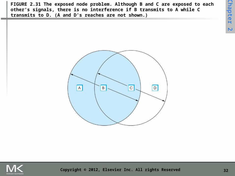
FIGURE 2.31 The exposed node problem. Although B and C are exposed to each other’s signals, there is no interference if B transmits to A while C transmits to D. (A and D’s reaches are not shown.)

33Copyright © 2012, Elsevier Inc. All rights Reserved
Chapter 2
FIGURE 2.32 Access points connected to a distribution system.

34Copyright © 2012, Elsevier Inc. All rights Reserved
Chapter 2
FIGURE 2.33 Node mobility.

35Copyright © 2012, Elsevier Inc. All rights Reserved
Chapter 2
FIGURE 2.34 802.11 frame format.

36Copyright © 2012, Elsevier Inc. All rights Reserved
Chapter 2
FIGURE 2.35 A Bluetooth piconet.

37Copyright © 2012, Elsevier Inc. All rights Reserved
Chapter 2
FIGURE 2.36 Diagram for Exercise 1.

38Copyright © 2012, Elsevier Inc. All rights Reserved
Chapter 2
FIGURE 2.37 Diagram for Exercises 36 to 38.


![Poster Programme - Elsevier · 5th International Conference on Bio-Sensing Technology I Poster Programme [P065] Electrochemical DNA biochips for detection of human papillomaviruses](https://img.pdfslide.net/doc/110x75/5e6cbbe33456e95f2d6d5b5c/poster-programme-elsevier-5th-international-conference-on-bio-sensing-technology.jpg)