Embed Size (px)
Citation preview
1
Cross-Layer Optimization for End-to-End Rate
Allocation in Multi-Radio Wireless Mesh Networks
Jian Tang1, Guoliang Xue2 and Weiyi Zhang2
1Department of Computer Science
Montana State University
Bozeman, MT 59717-3880.
Email: [email protected]
2Department of Computer Science and Engineering
Arizona State University
Tempe, AZ 85287-8809.
Email: {xue, weiyi.zhang}@asu.edu
Abstract
In this paper, we study rate allocation for a set of end-to-end communication sessions in multi-radio wireless
mesh networks. We propose cross-layer schemes to solve the joint rate allocation, routing, scheduling, power
control and channel assignment problems with the goals of maximizing network throughput and achieving certain
fairness. Fairness is addressed using both a simplified max-min fairness model and the well-known proportional
fairness model. Our schemes can also offer performance upper bounds such as an upper bound on the maximum
throughput. Numerical results show that our proportional fair rate allocation scheme achieves a good tradeoff
between throughput and fairness.
Index Item:Wireless mesh network, cross-layer optimization, rate allocation, channel assignment, fairness.
This research is supported in part by ARO grant W911NF-04-1-0385 and NSF grant CCF-0431167. The information reported here doesnot reflect the position or the policy of the federal government.
2
I. I NTRODUCTION
Wireless Mesh Networks (WMN) [1] are envisioned to provide various attractive applications in the
future, including broadband Internet access, distributed information sharing and storage, and different
multimedia applications at very low costs. Such networks can be deployed in both the urban and the rural
areas to offer a large range of wireless coverage. A WMN consists of wireless mesh routers and mesh
clients. Wireless mesh routers form a multihop wireless network which serves as the backbone to provide
network access for mesh clients.
Although a WMN is a multihop wireless network, it is quite different from other multihop wireless
networks, such as the well studied mobile ad hoc networks and wireless sensor networks. For example,
a mobile ad hoc network is composed of a set of power constrained mobile nodes. However, wireless
mesh routers in a WMN are usually stationary and directly connected with AC power. Therefore, major
concerns of a mobile ad hoc network, such as mobility support and power efficiency, are not the most
critical issues in a WMN.
All of the potential applications mentioned above demand the network to deliver a high volume of
traffic efficiently. Hence, how to improve network throughput should be the most important design goal of
WMNs. Moreover, every time when we talk about throughput, fairness must be taken into consideration,
as otherwise we will end up with a serious bias on network resource allocation, which has been shown
by previous research [11].
Compared with wired networks, a wireless network normally has lower network throughput due to
the existence of interference which prohibits simultaneous transmissions in a common neighborhood.
An effective method to improve throughput of wireless networks is to use multiple radios, i.e., to
equip each wireless node with multiple Network Interface Cards (NICs) and tune them to different
frequency channels [17], [18]. In a multi-radio wireless network, multiple transmissions within a common
neighborhood can be concurrently conducted as long as they work on different channels. However, in
order to make full use of the available NICs and channels, we have to carefully consider the channel
3
assignment problem, which has not been well addressed before and is shown to be a challenging problem
[18].
In this paper, we study a static network design problem, i.e., rate allocation, for a given set of end-to-
end communication sessions in multi-radio wireless mesh networks. The objective is to jointly compute
a rate allocation and the corresponding channel assignment, routing solution, transmission schedule and
power assignment such that network throughput can be maximized or certain fairness can be achieved. We
propose cross-layer schemes to solve the corresponding max throughput, max-min fair and proportional
fair rate allocation problems. For a given channel assignment and a set of given transmission modes, our
schemes offer the corresponding optimal rate allocation, routing and scheduling solutions, which will be
explained in detail later. In addition, our schemes can provide upper bounds on performances such as the
maximum throughput and the max-min rate value.
Many cross-layer schemes have been proposed for Multihop wireless networks. We summarize our
contributions and the differences between this work and previous related papers in the following.
• We are the first to cross four layers (the transport, network, MAC and physical layers) and study the
joint rate control, routing, scheduling, power control and channel assignment problems in multi-radio
WMNs. Among closely related works on multi-radio WMNs, power control was not addressed in [2],
[8], [13], [17], [18], [20], [21], [23], and scheduling was not considered in [8], [17], [18], [20], [21].
• Different from previous works on cross-layer optimization in single-channel multihop wireless net-
works [4], [6], [7], [9], [11], [12], [16], [19], [22] in which channel assignment is not a concern, we
consider the cross-layer optimization problems in the context of multi-radio WMNs and propose an
efficient channel assignment algorithm.
• We study a WMN with a scheduling-based MAC layer which is believed to be a more suitable MAC
solution for future WMNs [1] and adopted by the next generation wireless networking standard
802.16 [14]. In contrast, the 802.11-based MAC layer is assumed by most of related works [8], [17],
[18], [20], [21].
4
• We addresses fairness under different models, including both a simplified max-min model and the
well-known proportional fairness model. It differentiates this work from related works on multi-radio
WMNs, in which either end-to-end fairness was not seriously considered [8], [13], [17], [18], [20],
[23] or was only addressed based on the max-min fairness models [2], [21].
The rest of this paper is organized as follows. We discuss related works in Section II. We describe the
system model in Section III and define the problems in Section IV. The three cross-layer schemes and
the corresponding numerical results are presented in Sections V and VI, respectively. We conclude the
paper in Section VII.
II. RELATED WORK
Multi-radio WMNs have attracted extensive research attentions recently. Draveset al. in [8] presented
a new routing metric, Expected Transmission Time/Weighted Cumulative ETT (ETT/WCETT), and a
corresponding Multi-Radio Link-Quality Source Routing (MR-LQSR) protocol to find high-throughput
paths. In [17] and [18], the authors proposed one of the first802.11-based multi-radio WMN architectures
and developed a set of centralized and distributed channel assignment and routing heuristics. In [20],
Tang et al. presented interference-aware topology control and routing schemes for QoS provisioning.
Furthermore, they presented polynomial time optimal schemes to compute maximum throughput and fair
bandwidth allocation in [21]. A constant-bound approximation algorithm was proposed in [2] to jointly
compute channel assignment, routing and scheduling solutions for fair rate allocation. The authors of [13]
studied a similar problem and derived upper bounds on the achievable throughput using a fast primal-dual
algorithm. Based on that, they also proposed two channel assignment heuristics. Zhanget al. in [23]
developed a novel column generation based approach to solve the joint routing and scheduling problem.
Cross-layer approaches have been proposed to improve the performance of single-channel multihop
wireless networks. The authors of [6] formulated the joint design of congestion control and media access
control as a utility maximization problem and presented two distributed algorithms to solve it. In [22],
Wang and Kar proposed primal and dual based algorithms to compute proportional fair end-to-end rate
5
allocation in a multihop Aloha-based wireless network. Li in [16] considered end-to-end rate allocation in
wireless ad hoc networks and proposed algorithms to distribute resources among multihop flows with the
objective of improving both throughput and fairness. In [12], the authors studied the impact of interference
on routing using a conflict graph. They derived upper and lower bounds on the optimal network throughput.
In [11], Hou et al. developed a polynomial time algorithm to jointly calculate lexicographic max-min fair
rate allocation and routing solutions in two-tiered wireless sensor networks. Cross-layer congestion control
and power control design in wireless ad hoc networks have been studied by Chiang in [7]. The authors
of [9] studied the joint scheduling and power control problem in the wireless ad hoc and proposed a
simple two-phase heuristic to minimize the total power consumption. Similar cross-layer design problems
have also been studied [4] and [19] in which the authors presented both integer linear programming
formulations and fast heuristics for the considered problems.
III. SYSTEM MODEL
In this paper, we study a multi-radio wireless mesh backbone network withn stationary wireless mesh
routers in which there areC non-overlapping frequency channels and each node (mesh router)v is
equipped withQv NICs (1 < Qv ≤ W ). We consider static channel assignment schemes as in [2], [13],
[17], [18], i.e., a channel assignment is pre-determined and will not be changed during communications.
We consider a scheduling-based MAC layer, i.e., the time domain is divided into time slots with equal
constant durations, which are further grouped into frames ofL time slots each. In the physical layer, omni-
directional antennas are used for communications. The transmission power of a NIC can be adjusted within
a given range[0, Pmax]. However, it will remain the same within one time slot. Each NIC transmits at the
same fixed rate among all channels. As in all related works, we assume half-duplex operation at each NIC
to prevent self-interference, and only consider unicast communications. In addition, two transmissions
with a common receiver are not allowed to be made simultaneously, otherwise a collision will happen
and corrupt the packet reception. We use the physical model proposed in [10] to model the impact of
interference. We say a transmission from a transmitter in nodeu can be successfully received by a receiver
6
in nodev on a certain channel at some time instant, if
GuvPuv
N0 +∑
(x,y)∈τ\{(u,v)} GxvPxy
≥ β. (1)
In Inequality (1),τ stands for the set of concurrent transmissions;Puv is the power level set at the
transmitter of nodeu for transmission(u, v); Guv is the channel gain for node pair(u, v) depending on
path loss, channel fading and shadowing;β is a given threshold determined by some QoS requirements
such asBit Error Rate (BER); N0 is the thermal noise power at the receiver of nodev which is usually
a small constant. The left hand side of this inequality is normally called theSignal to Interference and
Noise Ratio (SINR)at the receiver of nodev. Note that the SINR constraint (Inequality (1)) is satisfied
at each receiver implies that the half-duplexing, unicasting and collision-free constraints are satisfied at
each receiver.
A directed graphG(V, E) is used to model the considered network. Each vertexv ∈ V corresponds
to a wireless mesh node in the network with a known location. There is a directed linke = (u, v) ∈ E
connecting nodeu and nodev if there exists a power levelP ∈ [0, Pmax] such thatGuvP/N0 ≥ β,
i.e., a transmission from nodeu to v can be successfully made if there is no interference from other
transmissions at the same time.
Multiple available radios complicate the transmission scheduling. Two neighbor nodes may share more
than one common channels, i.e., a link inG may work on different channels. So we have to use a link-
channel tuple(e, i) to uniquely denote the transmission along linke on channeli. Note that even though
we need to ensure half-duplex, unicast and collision-free communications in one NIC, two links sharing
one or two common nodes can be active for transmission as long as they work on different channels. For
a set of link-channel tuples having the same channel, we need to use the SINR constraint in Inequality (1)
to determine if they can be active for transmissions concurrently. Once a networkG and a corresponding
channel assignment are given, we can easily identify the setEI of possible link-channel tuples inG. For
example, suppose we have linke = (u, v) andA(u)⋂A(v) = {i, j}, then we will obtain two possible
7
link-channel tuples,(e, i) and (e, j).
IV. PROBLEM DEFINITION
Now we are ready to formally define the rate allocation problems. Suppose that we are given a network
G(V,E) and a set ofK end-to-end communication sessions. Each session is specified by a triple(s, t, d),
wheres is its source node,t is its destination node andd is its traffic demand. Like mentioned before,
the rate allocation problem is implicitly coupled with a routing problem, a scheduling problem, a power
control problem and a channel assignment problem. Hence, in all of the problems to be studied, we seek
an end-to-end rate allocation vectorr which specifies the raterk for each end-to-end sessionk, along with
a channel assignmentA specifying channels assigned to each node, a flow allocation vectorf specifying
the amount of trafficfkei of sessionk routed through linke on channeli, a frame lengthL, a transmission
schedule which specifies the set of link-channel tuples which are active in each time slot, and a power
assignment vector specifying the power level of each link-channel tuple in each time slot.
A channel assignment, a flow allocation vector, a transmission schedule and a power assignment vector
are said to befeasibleif (a) the channel assignmentA assigns a certain channel to each NIC and a set
A(v) of Qv different channels to each nodev, whereA(v) ⊆ {1, 2, . . . , W}; (b) for each session, the net
amount of flow going out of the source node is equal to the corresponding end-to-end session rate;(c) for
each session, the flow conservation constraint is satisfied at every node except the source and destination
nodes;(d) on each available link-channel tuple, the aggregated flow is no more than the mean link data
rate which can be supported by the transmission schedule; and(e) in each time slot and on each assigned
channel, there exists a power assignment vector, such that every power level is in the range[0, Pmax] and
the SINR constraint in Inequality 1 is satisfied at the receiving node of each link. A rate allocation vector
is said to befeasibleif we can find such a channel assignment, a flow allocation vector, a transmission
schedule, a frame lengthL and a power assignment vector that are feasible.
First, we define the Maximum throughput End-to-end Rate Allocation (MERA) problem as follows.
Definition 1 (MERA):The Maximum throughput End-to-end Rate Allocation (MERA) problem
8
seeks a feasible end-to-end rate allocation vectorr = [r1, r2, . . . , rK ], along with a feasible channel
assignment, a feasible flow allocation vector, a feasible transmission schedule, a frame lengthL and a
feasible power assignment vector such that the networkthroughput∑K
k=1 rk is maximized.
Because there is a traffic demand associated with each end-to-end communication session, which may
or may not be completely satisfied, we define a new variable calledDemand Satisfaction Factor (DSF)
to address the fairness. The DSF of a session is defined as the ratio between the rate actually allocated
to that session and its traffic demand, which indicates how much a traffic demand is satisfied based on
a rate allocation vector. So for each rate allocation vectorr = [r1, r2, . . . , rK ], we have a corresponding
DSF vectorα = [α1, α2, . . . , αK ], whereαk = rk/dk, 1 ≤ k ≤ K. The corresponding fair rate allocation
problems are defined in the following.
Definition 2 (MMERA):A feasible end-to-end rate allocation vectorr = [r1, r2, . . . , rK ] (α = [α1, α2,
. . . , αK ]) is said to be a feasiblemax-min guaranteed end-to-end rate allocation vectorif for any other
feasible end-to-end rate allocation vectorr′ = [r′1, r′2, . . . , r
′K ] (α′ = [α′1, α
′2, . . . , α
′K ]), min{αk|1 ≤ k ≤
K} ≥ min{α′k|1 ≤ k ≤ K}, whereα andα′ are the DSF vector corresponding tor andr′ respectively.
TheMax-Min guaranteed maximum throughput End-to-end rate allocation (MMERA) problem seeks
a feasible max-min guaranteed end-to-end rate allocation vector, along with a feasible channel assignment,
a feasible flow allocation vector, a feasible transmission schedule, a frame lengthL and a feasible power
assignment vector such that the networkthroughput∑K
k=1 rk is maximized.
Definition 3 (PERA):The Proportional fair End-to-end Rate Allocation (PERA) problem seeks a
end-to-end feasible rate allocation vectorr = [r1, r2, . . . , rK ] (α = [α1, α2, . . . , αK ]), along with a feasible
channel assignment, a feasible flow allocation vector, a feasible transmission schedule, a frame lengthL
and a feasible power assignment vector such that the utility function∑K
k=1 log (αk) is maximized, where
α is the DSF vector corresponding tor.
9
V. PROPOSEDCROSS-LAYER SCHEMES
The optimization problems defined in the last section involve four network layers. Without knowing
the channel assignment, it is hard to determine interference among transmissions to which transmission
scheduling and power control are highly related. Therefore, we propose 3-step heuristic methods to solve
the problems:In the first step, we propose LP and CP formulations for the MERA, MMERA and PERA
problems including the constraints placed by the nodes, channels, NIC, and the flow and rate feasibility
constraints. Note that the rate allocation given by these LP and CP formulations may not be achievable
because the wireless interference is not given full consideration in this phase. However, they can give
upper bounds on performances such as the maximum throughput and the max-min DSF. More importantly,
the flow allocation computed by solving the these LPs or CP, can provide a guidance for the channel
assignment. So based on them, we propose a channel assignment algorithm.In the second step, we identify
a set of transmission modes and compute their corresponding power assignments based on the channel
assignment determined in the first step. Here, each transmission mode corresponds to a set of link-channel
tuples which can be scheduled for transmissions in one time slot. The concept of transmission mode is
proposed to assist the computation of transmission schedule.In the third step, we present LP and CP
formulations to provide rate allocation, routing and scheduling solutions based on the channel assignment
and the transmission modes computed in the previous two steps.
A. Channel Assignment
In this section, we will first present LP and CP formulations to provide solutions which can be used
as the guidance for channel assignment. Then we will present the corresponding channel assignment
algorithm.
We define rate allocation variablesrk and DSF variablesαk to specify rate allocated to communication
sessionk and the corresponding DSF value respectively. We also have flow allocation variablesfkei
specifying the amount of flow for sessionk going through linke on channeli. We only allow non-
10
negative values for those variables.
We present an LP formulationLP1 to obtain approximate solutions of the MERA problem. In this
formulation,Eoutv , Ein
v andEv denote the set of outgoing, incoming and incident edges of nodev ∈ V .
ce, dk andQv are given parameters, and represent the capacity of linke, the traffic demand of sessionk
and the number of NICs in nodev respectively.
LP1:
maxK∑
k=1
rk (2)
subject to:
∑
e∈Eoutsk
C∑i=1
fkei −
∑
e∈Einsk
C∑i=1
fkei = rk, 1 ≤ k ≤ K; (3)
∑
e∈Eoutv
C∑i=1
fkei −
∑
e∈Einv
C∑i=1
fkei = 0, 1 ≤ k ≤ K, ∀v ∈ V \ {sk, tk}; (4)
∑e∈Ev
∑Kk=1 fk
ei
ce
≤ 1, ∀v ∈ V, 1 ≤ i ≤ C; (5)
C∑i=1
∑e∈Ev
∑Kk=1 fk
ei
ce
≤ Qv, ∀v ∈ V ; (6)
fkei ≥ 0, ∀e ∈ E, 1 ≤ i ≤ C, 1 ≤ k ≤ K; (7)
0 ≤ rk ≤ dk, 1 ≤ k ≤ K. (8)
Constraints (3)-(4) inLP1 are corresponding to the flow feasibility constraints(b) and (c) described
in the last section respectively. In order to explain the other two constraints, we define a new variablextei
whose value is1 if link e is active on channeli in time slot t, and whose value is0, otherwise. Then we
shall have the following two inequalities.
∑e∈Ev
xtei ≤ 1, 1 ≤ t ≤ L, 1 ≤ i ≤ C, ∀v ∈ V ; (9)
C∑i=1
∑e∈Ev
xtei ≤ Qv, 1 ≤ t ≤ L,∀v ∈ V. (10)
Inequality (9), i.e., in each node, at most one link can be active for transmissions on a certain channel
at one time, is due to the fact that channels assigned to NICs in one node must be different, and the
11
half-duplexing, unicasting and collision-free constraints in each NIC we mentioned before. We have
Inequality (10) because there areQv NICs in nodev. The mean flow over linke on channeli is given by
fei =∑K
k=1 fkei = ce ·(
∑Lt=1 xt
ei)/L. Hence, we have Constraints (5) and (6) inLP1. The objective ofLP1
is to maximize network throughput. Here, the scheduling and power control constraints are not included
in the formulation because the channel assignment is not known so far. We use this formulation to provide
an upper bound on the maximum achievable throughput and provide an approximate flow allocation to
guide channel assignment.
LP2:
max α (11)
subject to:
Constraints (4)− (7);
(∑
e∈Eoutsk
C∑i=1
fkei −
∑
e∈Einsk
C∑i=1
fkei)/dk = αk, 1 ≤ k ≤ K; (12)
α ≤ αk ≤ 1, 1 ≤ k ≤ K. (13)
LP3(α):
maxK∑
k=1
rk
subject to:
Constraints (3)− (7);
αdk ≤ rk ≤ dk, 1 ≤ k ≤ K. (14)
In order to obtain an approximate solution of the MMERA problem, we need to solve twoLPs
sequentially. First, we solveLP2 and obtain the max-min DSF valueα which is ensured by Constraint (13)
and the objective function ofLP2. Similar to the previous formulation, the computedα can serve as an
upper bound on the max-min DSF value. Then we feed this max-min DSF valueα as a parameter to
LP3(α) to obtain an approximate MMERA solution.
The PERA problem has almost the same set of linear constraints as the MERA and MMERA problems
and its objective is to maximize a concave utility function. Therefore, we can formulate and solve a CP
(CP1) to obtain the approximate solution.
12
CP1:
maxK∑
k=1
log(αk) (15)
subject to:
Constraints (4)− (7), (12);
0 ≤ αk ≤ 1, 1 ≤ k ≤ K. (16)
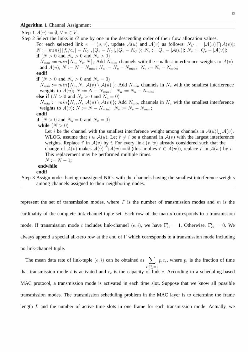
The channel assignment algorithm is formally presented as Algorithm 1. In this algorithm,fe denotes
the aggregated flow on linke which is given by the flow allocation solution computed by solving the
above LPs or CP. During the execution of the algorithm,NC records the number of common channels
in nodesu and v, and Nu and Nv record the number of available NICs in nodeu and v respectively.
N represents the number of required channels which is determined by the corresponding flow allocation
value in the selected linke and the numbers of available NICs in its end nodes. Theinterference weight
of a particular channel is defined asWI(i) =∑
l∈E\{e} f il ·Gs(l)t(e), wheref i
l records the flow through link
l on channeli; s(l), t(e) andGs(l)t(e) denote the transmitting node of linkl, the receiving node of linke
and the corresponding channel gain respectively. Every time when assigning a channeli to a link e, we
imaginecie amount of flow is allocated on link-channel tuple(e, i). The link-channel tuple flow values (f i
l )
are all initialized to0 and will be updated during the execution of the channel assignment algorithm. The
purpose of choosing channels with the smallest interference weight is to make the channels assigned to
spatially close nodes as different as possible. Note that in the replacement procedure of Step2, we always
use the selected channeli to replace a channel with the largest interference weight. In the worst-case, the
algorithm will eventually stop after passing through alln nodes and return to nodeu.
B. Transmission Modes and Power Control
Based on the channel assignment computed by Algorithm 1, we can easily identify all link-channel
tuples in the networkG. We denote such link-channel tuple set asEI. In order to compute the transmission
schedule, we define a set oftransmission modes, each of which includes a subset of link-channel tuples
that can be active for concurrent transmissions. Here, we introduce aT × m scheduling matrixΓ to
13
Algorithm 1 Channel Assignment
Step 1A(v) := ∅, ∀ v ∈ V .Step 2 Select the links inG one by one in the descending order of their flow allocation values.
For each selected linke = (u, v), updateA(u) and A(v) as follows: NC := |A(u)⋂A(v)|;
N := min{|dfe/cee −NC |, |Qu −NC |, |Qv −NC |}; Nu := Qu − |A(u)|; Nv := Qv − |A(v)|;if (N > 0 andNu > 0 andNv > 0)
Nmin := min{Nu, Nv, N}; Add Nmin channels with the smallest interference weights toA(v)andA(u); N := N −Nmin; Nu := Nu −Nmin; Nv := Nv −Nmin;
endifif (N > 0 andNu > 0 andNv = 0)
Nmin := min{Nu, N, |A(v) \ A(u)|}; Add Nmin channels inNv with the smallest interferenceweights toA(u); N := N −Nmin; Nu := Nu −Nmin;
else if (N > 0 andNv > 0 andNu = 0)Nmin := min{Nv, N, |A(u) \ A(v)|}; Add Nmin channels inNu with the smallest interferenceweights toA(v); N := N −Nmin; Nv := Nv −Nmin;
endifif (N > 0 andNu = 0 andNv = 0)while (N > 0)
Let i be the channel with the smallest interference weight among channels inA(u)⋃A(v).
WLOG, assume thati ∈ A(u). Let i′ 6= i be a channel inA(v) with the largest interferenceweights. Replacei′ in A(v) by i. For every link(v, w) already considered such that thechange ofA(v) makesA(v)
⋂A(w) = ∅ (this impliesi′ ∈ A(w)), replacei′ in A(w) by i.This replacement may be performed multiple times.N := N − 1;
endwhileendif
Step 3 Assign nodes having unassigned NICs with the channels having the smallest interference weightsamong channels assigned to their neighboring nodes.
represent the set of transmission modes, whereT is the number of transmission modes andm is the
cardinality of the complete link-channel tuple set. Each row of the matrix corresponds to a transmission
mode. If transmission modet includes link-channel(e, i), we haveΓtei = 1. Otherwise,Γt
ei = 0. We
always append a special all-zero row at the end ofΓ which corresponds to a transmission mode including
no link-channel tuple.
The mean data rate of link-tuple(e, i) can be obtained as∑
t:Γtei=1
ptce, wherept is the fraction of time
that transmission modet is activated andce is the capacity of linke. According to a scheduling-based
MAC protocol, a transmission mode is activated in each time slot. Suppose that we know all possible
transmission modes. The transmission scheduling problem in the MAC layer is to determine the frame
length L and the number of active time slots in one frame for each transmission mode. Actually, we
14
can calculate a frame length by finding the smallest positive integerL such thatpt · L is an integer for
every transmission mode. Correspondingly, transmission modet should be activated inpt · L time slots.
Therefore, the scheduling problem is further transformed into a problem of computing the time fraction
for each transmission mode. However, it may be impossible to find such an integerL sincept could be
an irrational number. In this case,pt can be rounded up to obtain an frame lengthL, which will be a
very close approximation.
The number of all possible transmission modes grows exponentially with the number of link-channel
tuples. To our best knowledge, there does not exist a polynomial time algorithm which can identify all
possible transmission modes based on the physical interference model in the literature. Therefore, we
present a heuristic algorithm, Algorithm 2, to find a “good” subset of all possible transmission modes.
Intuitively speaking, a good subset should cover all link-channel tuples and the number of times every
tuple is included in certain transmission modes should be evenly distributed.
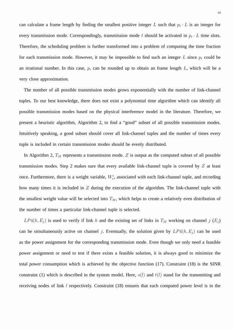
In Algorithm 2, TM represents a transmission mode.Z is output as the computed subset of all possible
transmission modes. Step 2 makes sure that every available link-channel tuple is covered byZ at least
once. Furthermore, there is a weight variable,W ie , associated with each link-channel tuple, and recording
how many times it is included inZ during the execution of the algorithm. The link-channel tuple with
the smallest weight value will be selected intoTM , which helps to create a relatively even distribution of
the number of times a particular link-channel tuple is selected.
LP4(h,Ej) is used to verify if linkh and the existing set of links inTM working on channelj (Ej)
can be simultaneously active on channelj. Eventually, the solution given byLP4(h,Ej) can be used
as the power assignment for the corresponding transmission mode. Even though we only need a feasible
power assignment or need to test if there exists a feasible solution, it is always good to minimize the
total power consumption which is achieved by the objective function (17). Constraint (18) is the SINR
constraint (1) which is described in the system model. Here,s(l) and t(l) stand for the transmitting and
receiving nodes of linkl respectively. Constraint (18) ensures that each computed power level is in the
15
range[0, Pmax].
Algorithm 2 Finding Transmission Mode Set
Step 1 Z := Ø; i := 1; W ie := 0, ∀(e, i) ∈ EI;
Step 2 while (i <= ω)TM := Ø;forall ((e, i) ∈ EI)Add (e, i) to TM ; W i
e := W ie + 1;
do Add (h, j) 6= (e, i) to TM ,s.t. LP4(h,Ej) has a feasible solution
andW jh is minimum among all
link-channel tuples not inTM ;W j
h := W jh + 1;
until no more link-channel tuple can be added toTM ;if (TM /∈ Z)
Z := Z ∪ {TM};endif
endforalli := i + 1;
endwhileStep 3 output Z;
LP4(h,Ej):
min∑
l∈Ej⋃{h}
Pl (17)
subject to:
Gs(l)t(l)Pl − β∑
q∈Ej⋃{h}\{l}
Gs(q)t(l)Pq − βN0 ≥ 0, ∀l ∈ Ej
⋃{h}; (18)
0 ≤ Pl ≤ Pmax, ∀l ∈ Ej
⋃{h}. (19)
In Step 2 of Algorithm 2,ω is a tunable parameter. We observe that the larger theω is, the more
transmission modes will be added intoZ, which will make the final solutions closer to the optimal ones
at the cost of increasing the time complexities of our schemes.
C. Rate Allocation
In this section, we present LP and CP formulations for the MERA, MMERA and PERA problems based
on the set of transmission modes computed in the second step and the channel assignment computed in
the first step.
16
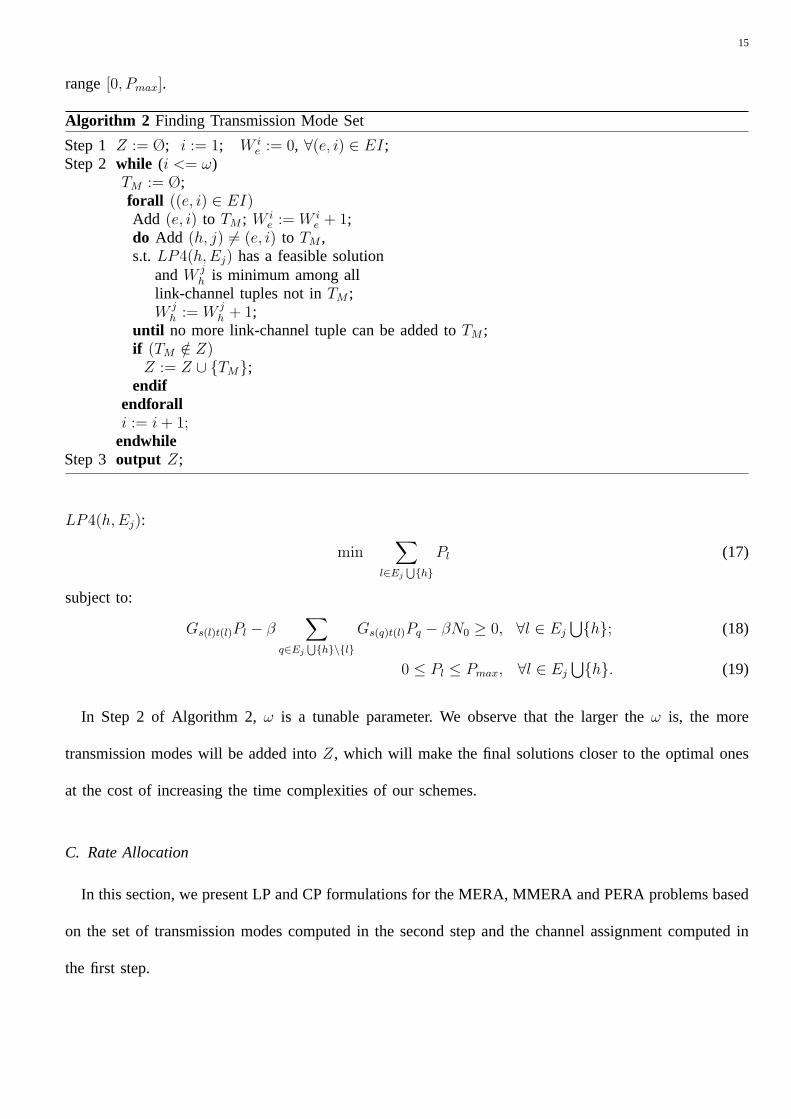
LP5: MERA
maxK∑
k=1
rk
subject to:
(∑
(e,i)∈EIoutsk
fkei −
∑
(e,i)∈EIinsk
fkei) = rk, 1 ≤ k ≤ K; (20)
∑
(e,i)∈EIoutv
fkei −
∑
(e,i)∈EIinv
fkei = 0, 1 ≤ k ≤ K, ∀v ∈ V \ {sk, tk}; (21)
K∑
k=1
fkei ≤
∑
t:Γtei=1
ptce, ∀(e, i) ∈ EI; (22)
T∑t=1
pt = 1; (23)
fkei ≥ 0, ∀(e, i) ∈ EI, 1 ≤ k ≤ K; (24)
0 ≤ rk ≤ dk, 1 ≤ k ≤ K.
In the above LP formulation, we have the aforementioned rate allocation variablesrk and flow allocation
variablesfkei and the transmission schedule variablespt. EIout
v , EI inv andEIv denote the set of link-channel
tuples whose corresponding links are the outgoing, incoming and incident links of nodev ∈ V respectively.
Similar to LP1, Constraints (20) and (21) correspond to the flow feasibility constraints. Constraints (22)
guarantees that the mean data rate of a specific link on a certain channel given by the transmission schedule
is large enough to support the amount of traffic going through that link on that channel. Obviously, since
pt is the fraction of time using transmission modet, the summation of the values ofpt should be equal
to 1, which is ensured by Constraint(23).
Similar asLP2, LP3, we useLP6 to find max-min rate allocation valueα first and then solveLP7(α)
which takesα as a parameter to compute the max-min guaranteed maximum throughput rate allocation.
In addition, we present a CP formulation,CP2, to compute the proportional fair rate allocation.
LP6:
max α
17
subject to:
Constraints (21)− (24);
(∑
(e,i)∈EIoutsk
fkei −
∑
(e,i)∈EIinsk
fkei)/dk = αk, 1 ≤ k ≤ K; (25)
α ≤ αk ≤ 1, 1 ≤ k ≤ K.
LP7(α): MMERA
maxK∑
k=1
rk
subject to:
Constraints (20)− (24);
αdk ≤ rk ≤ dk, 1 ≤ k ≤ K.
CP2: PERA
maxK∑
k=1
log(αk)
subject to:
Constraints (21)− (24), (25);
0 ≤ αk ≤ 1, 1 ≤ k ≤ K.
In summary, our MERA scheme is to1) apply Algorithm 1 to compute a channel assignment based on
the flow allocation given by solvingLP1; 2) use Algorithm 2 to find a set of transmission modes and their
corresponding power assignments according to the channel assignment computed in1); 3) solveLP5 to
find a rate allocation, a flow allocation and a scheduling solution for the MERA problem. Similarly, our
MMERA (PERA) scheme is to apply Algorithm 1 based onLP2 andLP3 (CP1), use Algorithm 2, and
then solveLP6 andLP7 (CP2).
VI. N UMERICAL RESULTS
In this section, we illustrate the performances of the three cross-layer schemes by numerical results. In
our simulations, we consider wireless networks with static nodes randomly located in a1200× 1200 m2
region. The maximum transmission power is set toPmax = 300mW . The thermal noise power is set to
N0 = −90dBm. The SINR threshold is set toβ = 10dB. The channel gain,Guv is set to1/d4uv, where
duv is the Euclidean distance between nodeu and nodev. For each simulation scenario, we generate end-
18
to-end communication sessions with random source and destination nodes. The traffic demand for each
communication session (dk) is given by a random number uniformly distributed in[0.2c, 0.6c], wherec is
the link capacity. We solve all LPs usingCPLEX 9.0[15]. We implement the barrier method introduced
in Chapter11 of [5] to solve all CPs and set the related parameters as follows:ε = 10−3, µ = 120 and
t(0) = 2.
We evaluate the performance of the three rate allocation schemes in terms of the DSF value of each
session (αk) and network throughput (∑K
k=1 rk). We also compare the computed throughput and max-min
DSF values against the corresponding upper bounds. For the MERA and PERA scheme, the upper bound
ratio is defined as the ratio between the actual throughput and its corresponding upper bound obtained by
solving LP1 or CP1. For the MMERA scheme, the upper bound ratio is defined as the ratio between
the actual max-min DSF value and its corresponding upper bound given by solvingLP2 andLP3.
We evaluate the performance of the proposed schemes under different settings, i.e., different network
sizes (n), different number of end-to-end sessions (K), different numbers of available channels (C), and
different numbers of NICs (Q) in each node and different link capacities (c). The simulation results are
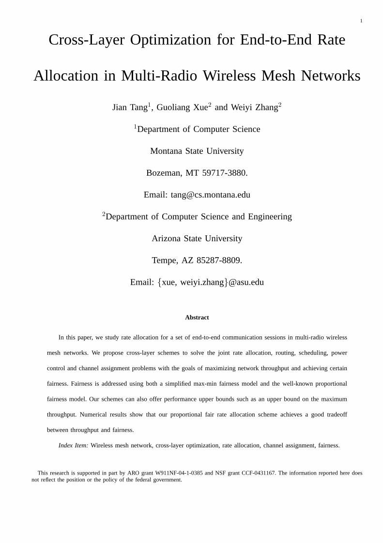
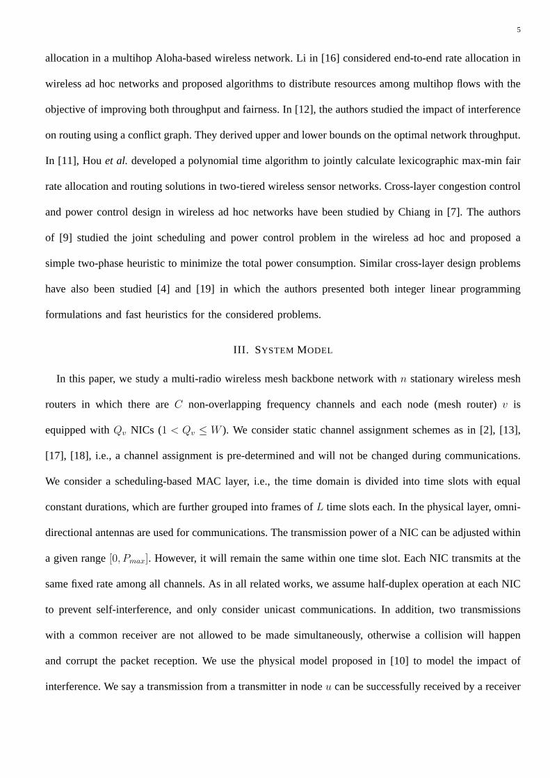
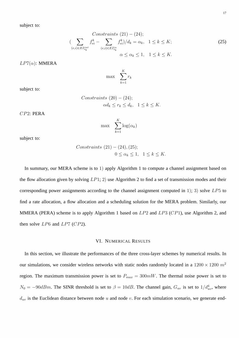
presented in the following figures. In Figure 1–Figure 5, the communication sessions are sorted in the
non-descending order based on their DSF values.
1 2 3 4 5 6 7 8 9 10 11 12 13 14 150
0.1
0.2
0.3
0.4
0.5
0.6
0.7
0.8
0.9
1
Sorted Session Index
DS
F
MERAMMERAPERA
Fig. 1. DSF: Scenario1 (n = 10, K = 15, C = 3, Q = 2, c = 11)
We make the following observations from the numerical results:
19
1 2 3 4 5 6 7 8 9 10 11 12 13 14 150
0.1
0.2
0.3
0.4
0.5
0.6
0.7
0.8
0.9
1
Sorted Session Index
DS
F
MERAMMERAPERA
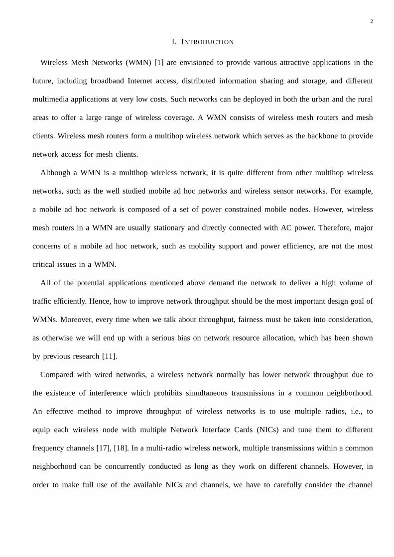
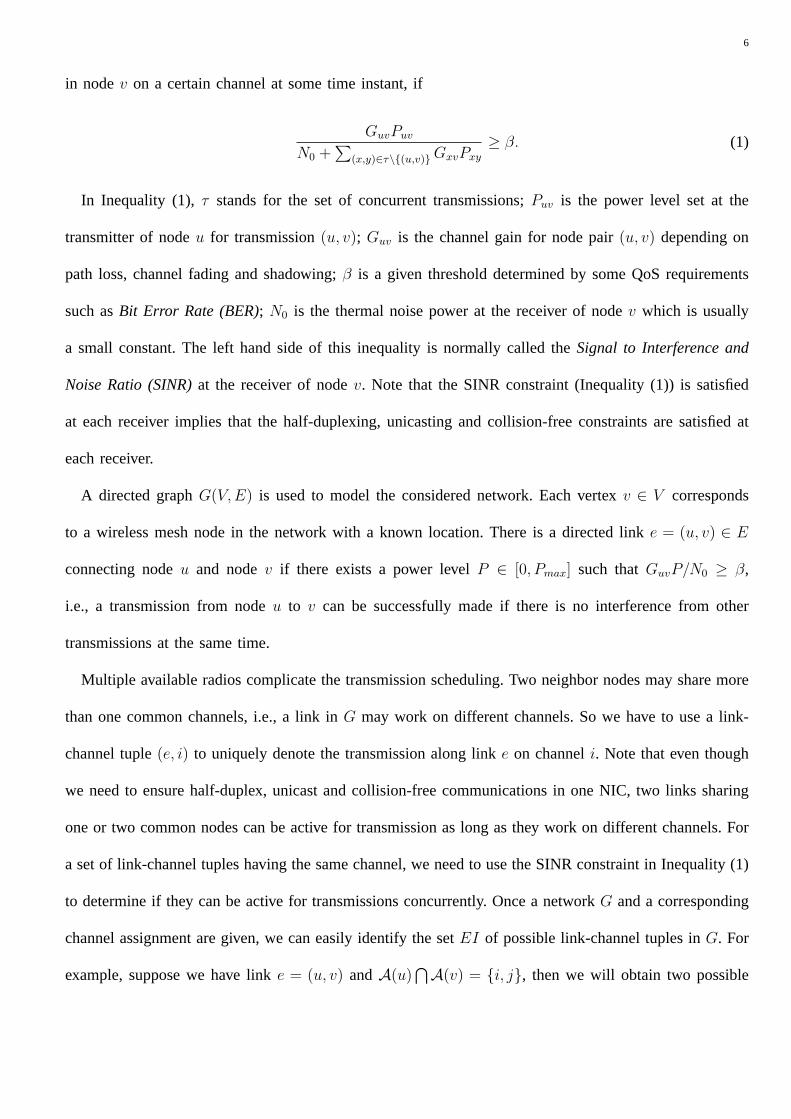
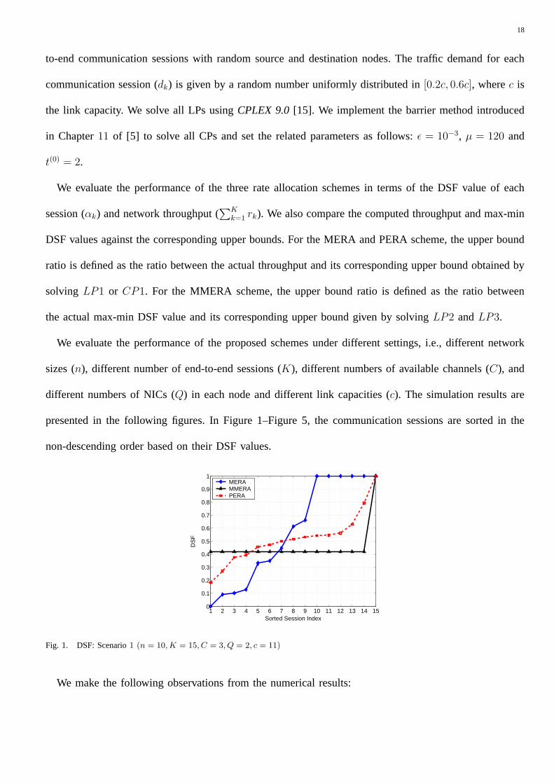
Fig. 2. DSF: Scenario2 (n = 15, K = 15, C = 3, Q = 2, c = 11)
1 2 3 4 5 6 7 8 9 10 11 12 13 14 15 16 17 18 19 200
0.1
0.2
0.3
0.4
0.5
0.6
0.7
0.8
0.9
1
Sorted Session Index
DS
F
MERAMMERAPERA
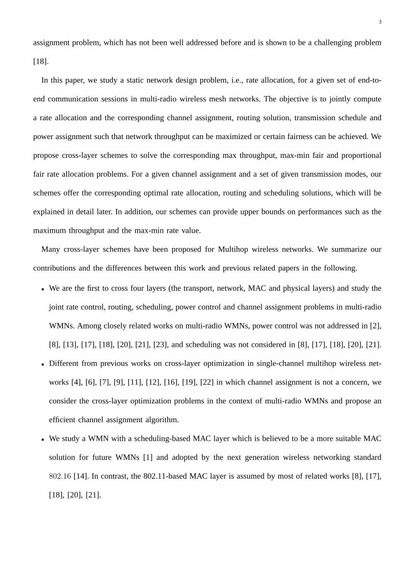
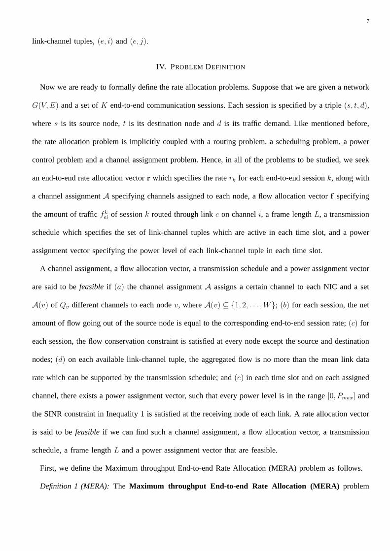
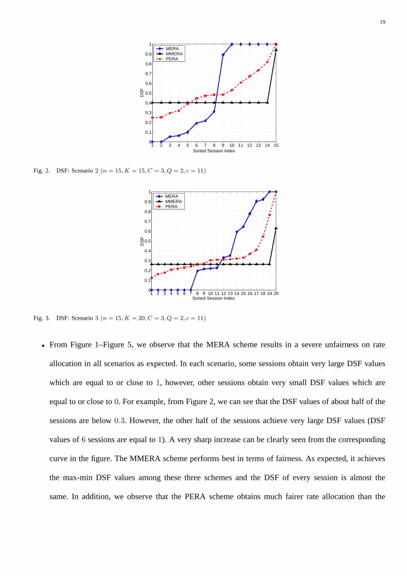
Fig. 3. DSF: Scenario3 (n = 15, K = 20, C = 3, Q = 2, c = 11)
• From Figure 1–Figure 5, we observe that the MERA scheme results in a severe unfairness on rate
allocation in all scenarios as expected. In each scenario, some sessions obtain very large DSF values
which are equal to or close to1, however, other sessions obtain very small DSF values which are
equal to or close to0. For example, from Figure 2, we can see that the DSF values of about half of the
sessions are below0.3. However, the other half of the sessions achieve very large DSF values (DSF
values of6 sessions are equal to1). A very sharp increase can be clearly seen from the corresponding
curve in the figure. The MMERA scheme performs best in terms of fairness. As expected, it achieves
the max-min DSF values among these three schemes and the DSF of every session is almost the
same. In addition, we observe that the PERA scheme obtains much fairer rate allocation than the
20
1 2 3 4 5 6 7 8 9 10 11 12 13 14 150
0.1
0.2
0.3
0.4
0.5
0.6
0.7
0.8
0.9
1
Sorted Session Index
DS
F
MERAMMERAPERA
Fig. 4. DSF: Scenario4 (n = 10, K = 15, C = 5, Q = 2, c = 54)
1 2 3 4 5 6 7 8 9 10 11 12 13 14 150
0.1
0.2
0.3
0.4
0.5
0.6
0.7
0.8
0.9
1
Sorted Session Index
DS
F
MERAMMERAPERA
Fig. 5. DSF: Scenario5 (n = 10, K = 15, C = 5, Q = 3, c = 54)
MERA scheme. In all scenarios, the minimum DSF values obtained by the PERA scheme are always
larger than those obtained by the MERA scheme. Furthermore, the curves corresponding to the PERA
scheme are much smoother than those corresponding to the MERA scheme.
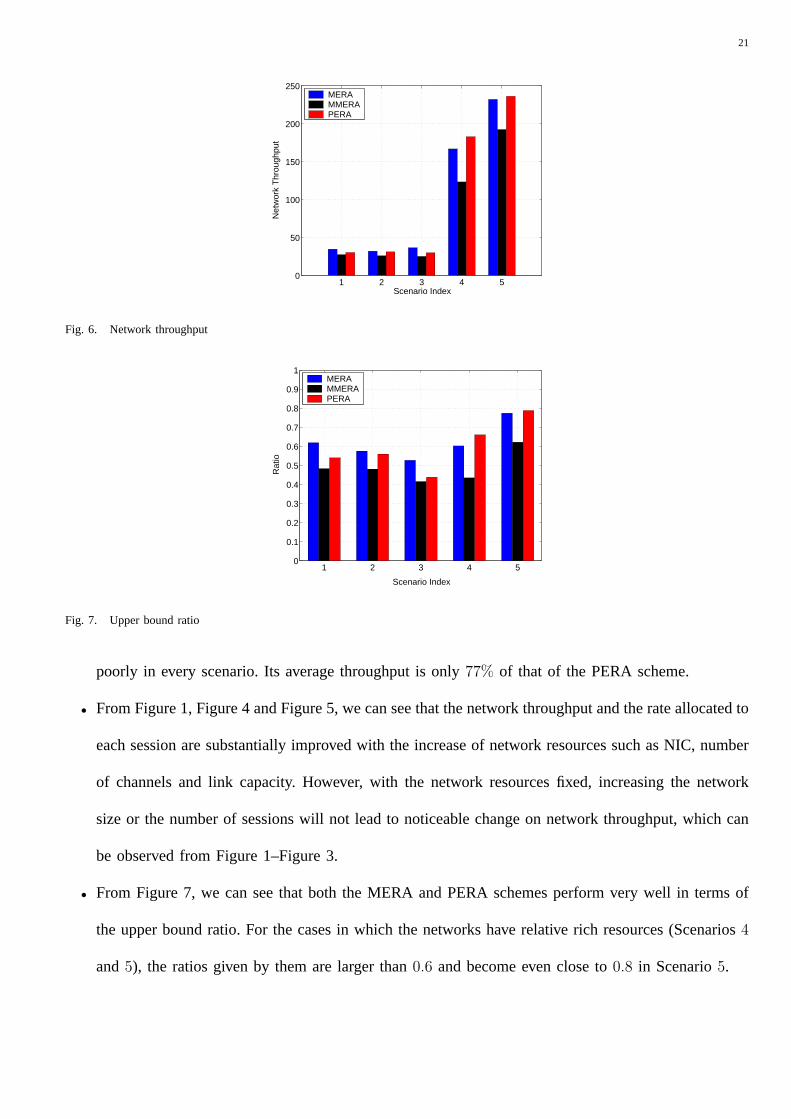
• With regards to network throughput, the PERA scheme is surprisingly good, which can be seen from
Figure 6. Compared with the MERA scheme, the PERA scheme provides comparable throughput
in Scenario1, 2 and3, and achieves even higher throughput in Scenarios4 and5. This is possible
because our MERA scheme is a heuristic scheme which does not guarantee to find the maximum
throughput solutions even though its objective is to maximize the throughput. On average, these
two schemes lead to almost the same network throughput. However, the MMERA scheme performs
21
1 2 3 4 50
50
100
150
200
250
Scenario Index
Net
wor
k T
hrou
ghpu
t
MERAMMERAPERA
Fig. 6. Network throughput
1 2 3 4 50
0.1
0.2
0.3
0.4
0.5
0.6
0.7
0.8
0.9
1
Scenario Index
Rat
io
MERAMMERAPERA
Fig. 7. Upper bound ratio
poorly in every scenario. Its average throughput is only77% of that of the PERA scheme.
• From Figure 1, Figure 4 and Figure 5, we can see that the network throughput and the rate allocated to
each session are substantially improved with the increase of network resources such as NIC, number
of channels and link capacity. However, with the network resources fixed, increasing the network
size or the number of sessions will not lead to noticeable change on network throughput, which can
be observed from Figure 1–Figure 3.
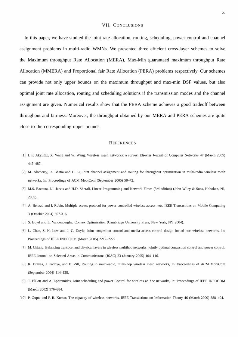
• From Figure 7, we can see that both the MERA and PERA schemes perform very well in terms of
the upper bound ratio. For the cases in which the networks have relative rich resources (Scenarios4
and5), the ratios given by them are larger than0.6 and become even close to0.8 in Scenario5.
22
VII. C ONCLUSIONS
In this paper, we have studied the joint rate allocation, routing, scheduling, power control and channel
assignment problems in multi-radio WMNs. We presented three efficient cross-layer schemes to solve
the Maximum throughput Rate Allocation (MERA), Max-Min guaranteed maximum throughput Rate
Allocation (MMERA) and Proportional fair Rate Allocation (PERA) problems respectively. Our schemes
can provide not only upper bounds on the maximum throughput and max-min DSF values, but also
optimal joint rate allocation, routing and scheduling solutions if the transmission modes and the channel
assignment are given. Numerical results show that the PERA scheme achieves a good tradeoff between
throughput and fairness. Moreover, the throughput obtained by our MERA and PERA schemes are quite
close to the corresponding upper bounds.
REFERENCES
[1] I. F. Akyildiz, X. Wang and W. Wang, Wireless mesh networks: a survey, Elsevier Journal of Computer Networks 47 (March 2005)
445–487.
[2] M. Alicherry, R. Bhatia and L. Li, Joint channel assignment and routing for throughput optimization in multi-radio wireless mesh
networks, In: Proceedings of ACM MobiCom (September 2005) 58–72.
[3] M.S. Bazaraa, J.J. Jarvis and H.D. Sherali, Linear Programming and Network Flows (3rd edition) (John Wiley & Sons, Hoboken, NJ,
2005).
[4] A. Behzad and I. Rubin, Multiple access protocol for power controlled wireless access nets, IEEE Transactions on Mobile Computing
3 (October 2004) 307-316.
[5] S. Boyd and L. Vandenberghe, Convex Optimization (Cambridge University Press, New York, NY 2004).
[6] L. Chen, S. H. Low and J. C. Doyle, Joint congestion control and media access control design for ad hoc wireless networks, In:
Proceedings of IEEE INFOCOM (March 2005) 2212–2222.
[7] M. Chiang, Balancing transport and physical layers in wireless multihop networks: jointly optimal congestion control and power control,
IEEE Journal on Selected Areas in Communicatons (JSAC) 23 (January 2005) 104–116.
[8] R. Draves, J. Padhye, and B. Zill, Routing in multi-radio, multi-hop wireless mesh networks, In: Proceedings of ACM MobiCom
(September 2004) 114–128.
[9] T. ElBatt and A. Ephremides, Joint scheduling and power Control for wireless ad hoc networks, In: Proceedings of IEEE INFOCOM
(March 2002) 976–984.
[10] P. Gupta and P. R. Kumar, The capacity of wireless networks, IEEE Transactions on Information Theory 46 (March 2000) 388–404.
23
[11] Y. T. Hou, Y. Shi and H. D. Sherali, Rate allocation in wireless sensor networks with network lifetime requirement, In: Proceedings
of ACM MobiHoc (May 2004) 67–77.
[12] K. Jain, J. Padhye, V. Padmanabhan and L. Qiu, Impact on interference on multihop wireless network performance, In: Proceedings
of ACM MobiCom (September 2003) 66–80.
[13] M. Kodialam and T. Nandagopal, Characterizing the capacity region in multi-radio multi-channel wireless mesh networks, In:
Proceedings of ACM MobiCom (September 2005) 73–87.
[14] IEEE 802.16 Working Group, Air Interface For Fixed Broadband Wireless Access Systems (IEEE, Washington D.C., 2004).
[15] ILOG Software Inc., CPLEX 9.0, Available at http://www.ilog .com/products/cplex/news/whatsnew.cfm#cplex90
[16] B. Li, End-to-end fair bandwidth allocation in multi-hop wireless ad hoc networks, In: Proceedings of IEEE ICDCS (June 2005)
471–480.
[17] A. Raniwala and T. Chiueh, Architecture and algorithms for an IEEE802.11-based multi-channel wireless mesh network, In: Proceedings
of IEEE INFOCOM (March 2005) 2223–2234.
[18] A. Raniwala, K. Gopalan and T. Chiueh, Centralized channel assignment and routing algorithms for multi-channel wireless mesh
networks, ACM Mobile Computing and Communications Review (MC2R) 8 (April 2004) 50–65.
[19] J. Tang, G. Xue, C. Chandler and W. Zhang, Link scheduling with power control for throughput enhancement in multihop wireless
networks, IEEE Transactions on Vehicular Technology (TVT) 55 (May 2006) 733–742.
[20] J. Tang, G. Xue and W. Zhang, Interference-aware topology control and QoS routing in multi-channel wireless mesh networks, In:
Proceedings of ACM MobiHoc (May 2005) 68–77.
[21] J. Tang, G. Xue and W. Zhang, Maximum throughput and fair bandwidth allocation in multi-channel wireless mesh networks, In:
Proceedings of IEEE INFOCOM (April 2006).
[22] X. Wang and K. Kar, Cross-layer rate control for end-to-end proportional fairness in wireless networks with random access, In:
Proceedings of ACM MobiHoc (May 2005) 158–168.
[23] J. Zhang, H. Wu, Q. Zhang and B. Li, Joint routing and scheduling in multi-radio multi-channel multi-hop wireless networks, In:
Proceedings of IEEE BROADNETS (October 2005) 678–687.
24
Jian Tang is an assistant professor in the Department of Computer Science at Montana State University. He received
the Ph.D degree in Computer Science from Arizona State University in 2006. His research interest is in the area of
wireless networking and mobile computing. He has served on the technical program committees of multiple international
conferences, including ICC, Globecom, IPCCC and QShine. He will also serve as a publicity co-chair ofInternational
Conference on Autonomic Computing and Communication Systems (Autonomics’2007).
Guoliang Xue is a Full Professor in the Department of Computer Science and Engineering at Arizona State University.
He received the Ph.D degree in Computer Science from the University of Minnesota in 1991 and has held previous
positions at the Army High Performance Computing Research Center and the University of Vermont. His research
interests include efficient algorithms for optimization problems in networking, with applications to fault tolerance,
robustness, and privacy issues in networks ranging from WDM optical networks to wireless ad hoc and sensor networks.
He has published over 150 papers in these areas. His research has been continuously supported by federal agencies including NSF and ARO.
He is the recipient of anNSF Research Initiation Award in 1994 and anNSF-ITR Award in 2003. He is an Associate Editor ofComputer
Networks (COMNET), the IEEE Network Magazine, and Journal of Global Optimization. He has served on the executive/program
committees of many IEEE conferences, including INFOCOM, SECON, IWQOS, ICC, GLOBECOM and QShine. He is the General Chair
of IEEE IPCCC’2005, a TPC co-Chair ofIPCCC’2003, HPSR’2004, IEEE Globecom’2006 Symposium on Wireless Ad Hoc and Sensor
Networks, IEEE ICC’2007 Symposium on Wireless Ad Hoc and Sensor Networks, andQShine’2007. He is a senior member of IEEE.
Weiyi Zhang received the M.E. degree in 1999 from Southeast University, China. Currently he is a Ph.D student in the
Department of Computer Science and Engineering at Arizona State University. His research interests include reliable
communication in networking, protection and restoration in WDM networks, and QoS provisioning in communication
networks.


![The Transport Layercs168/fa14/lectures/lec10-public.pdf · Role of the Transport Layer ! Communication between processes ! Provide common end-to-end services for app layer [optional]](https://img.pdfslide.net/doc/110x75/5f39bdcea7c9c7085a5af40d/the-transport-layer-cs168fa14lectureslec10-publicpdf-role-of-the-transport.jpg)