Embed Size (px)
Citation preview
1 CypNest Nesting Software User Manual
Welcome
Thank you for using CypNest nesting software!
CypNest is designed for providing nesting solutions for laser cutting industry,
especially for Friendess CypCut users to meet the automation requirements of
drawing processing, nesting, tool path generation and remote task transmission etc.
This document is based on CypNest 6.3.740.3, for continuous update of the
program, there will be some difference from latest CypNest you are using and the
document statement. We apologize for any inconvenience caused.
If you have any question or advice in use of our products, welcome to contact us.
CypNest Nesting Software User Manual 2
Contents
Chapter 1 Installation and registration ............................................................................................. 3
1.1 Dongle registration ........................................................................................................... 3
Chapter 2 Nesting task ..................................................................................................................... 4
2.1 Create a task .......................................................................................................................... 5 2.2 Add parts ............................................................................................................................... 8
2.2.1 Add from file and edit .................................................................................................... 8 2.2.2 Import from file ........................................................................................................... 11
2.3 Add sheet and sheet setting.................................................................................................. 12 2.4 Manual nesting .................................................................................................................... 12 2.5 Auto nest .............................................................................................................................. 14
Chapter 3 Common line tool path .................................................................................................. 16
3.1 Common line array .............................................................................................................. 16 3.1.1 Common line first ........................................................................................................ 16 3.1.2 C-type cutting line ....................................................................................................... 18 3.1.3 Cutting by part ............................................................................................................. 19
3.2 Custom common line ........................................................................................................... 21
Chapter 4 Processing settings ......................................................................................................... 22
4.1 Graphic technique settings .................................................................................................. 22 4.2 Batch modification .............................................................................................................. 22 4.3 Auto sort .............................................................................................................................. 22
4.3.1 Part sort ........................................................................................................................ 23 4.4 Manual sort: ......................................................................................................................... 24
4.4.1 Part sort ........................................................................................................................ 24 4.4.2 In-part sort ................................................................................................................... 25
4.5 Remnant .............................................................................................................................. 25
Chapter 5 Export cutting file .......................................................................................................... 27
5.1 Report .................................................................................................................................. 27 5.2 Export cutting file ................................................................................................................ 28

3 CypNest Nesting Software User Manual
Chapter 1 Installation and registration
Microsoft Windows 7 and above required for the CypNest normal operation.
1.1 Dongle registration
Dongle users only need to insert dongle to computer then open the software
without registration.
CypNest Nesting Software User Manual 4
Chapter 2 Nesting task
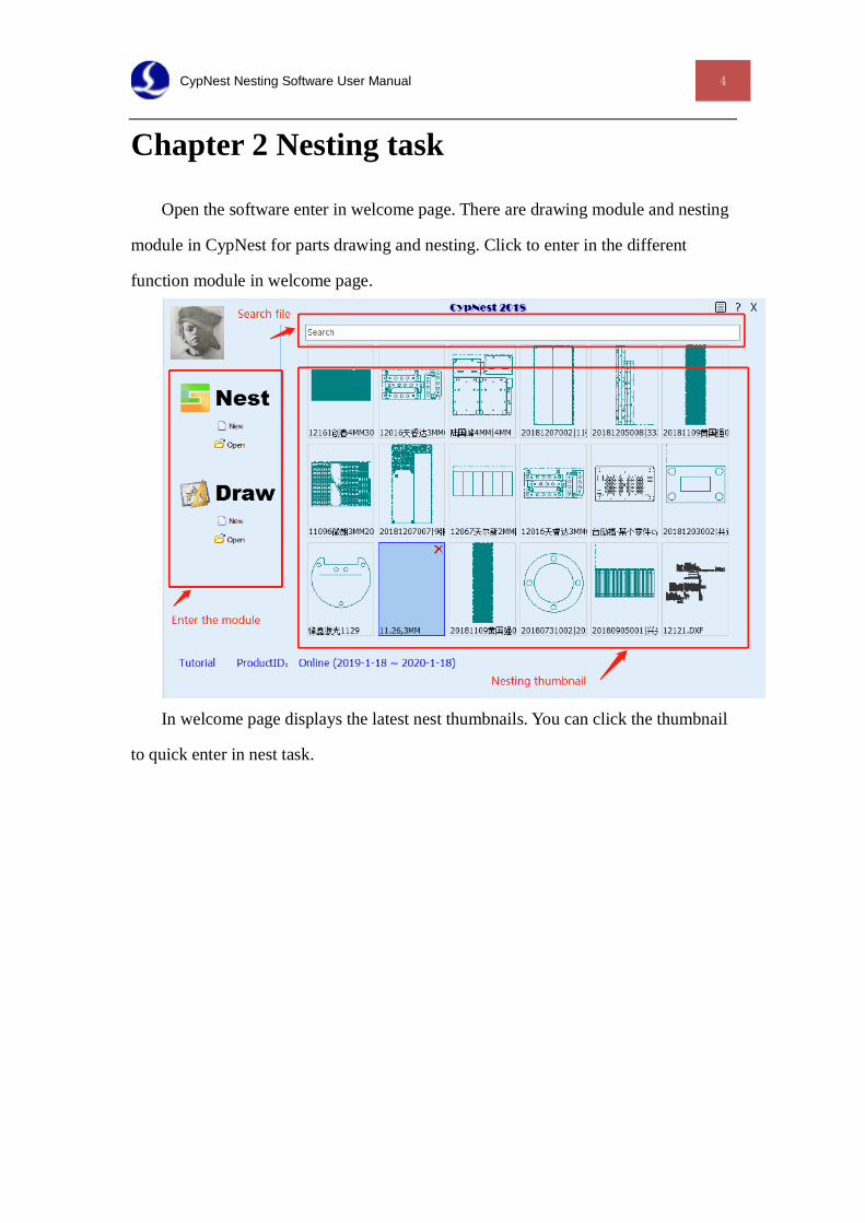
Open the software enter in welcome page. There are drawing module and nesting
module in CypNest for parts drawing and nesting. Click to enter in the different
function module in welcome page.
In welcome page displays the latest nest thumbnails. You can click the thumbnail
to quick enter in nest task.
5 CypNest Nesting Software User Manual
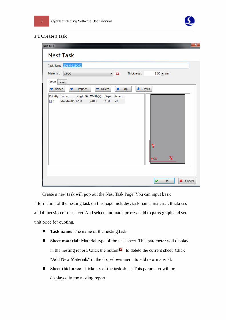
2.1 Create a task
Create a new task will pop out the Nest Task Page. You can input basic
information of the nesting task on this page includes: task name, material, thickness
and dimension of the sheet. And select automatic process add to parts graph and set
unit price for quoting.
Task name: The name of the nesting task.
Sheet material: Material type of the task sheet. This parameter will display
in the nesting report. Click the button to delete the current sheet. Click
"Add New Materials" in the drop-down menu to add new material.
Sheet thickness: Thickness of the task sheet. This parameter will be
displayed in the nesting report.
CypNest Nesting Software User Manual 6
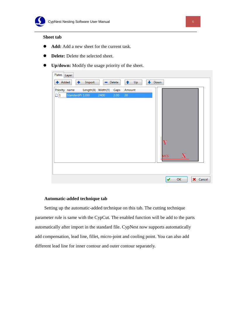
Sheet tab
Add: Add a new sheet for the current task.
Delete: Delete the selected sheet.
Up/down: Modify the usage priority of the sheet.
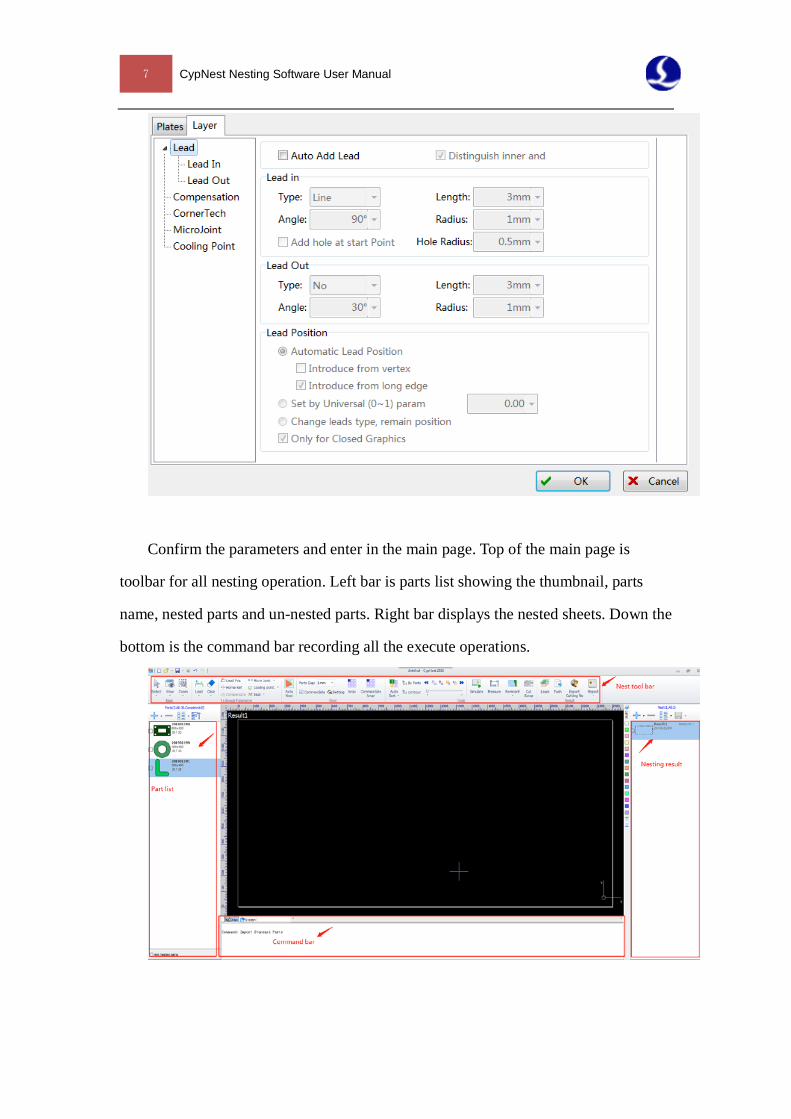
Automatic-added technique tab
Setting up the automatic-added technique on this tab. The cutting technique
parameter rule is same with the CypCut. The enabled function will be add to the parts
automatically after import in the standard file. CypNest now supports automatically
add compensation, lead line, fillet, micro-joint and cooling point. You can also add
different lead line for inner contour and outer contour separately.
7 CypNest Nesting Software User Manual
Confirm the parameters and enter in the main page. Top of the main page is
toolbar for all nesting operation. Left bar is parts list showing the thumbnail, parts
name, nested parts and un-nested parts. Right bar displays the nested sheets. Down the
bottom is the command bar recording all the execute operations.
CypNest Nesting Software User Manual 8
2.2 Add parts
2.2.1 Add from file and edit
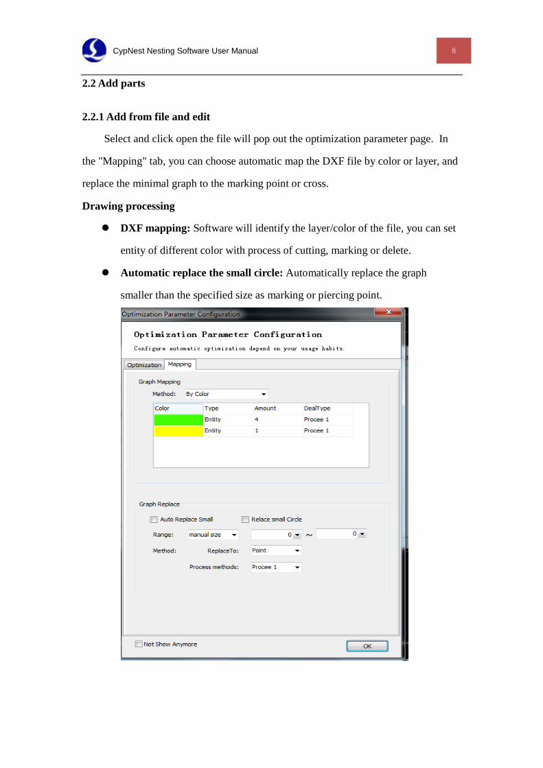
Select and click open the file will pop out the optimization parameter page. In
the "Mapping" tab, you can choose automatic map the DXF file by color or layer, and
replace the minimal graph to the marking point or cross.
Drawing processing
DXF mapping: Software will identify the layer/color of the file, you can set
entity of different color with process of cutting, marking or delete.
Automatic replace the small circle: Automatically replace the graph
smaller than the specified size as marking or piercing point.
9 CypNest Nesting Software User Manual
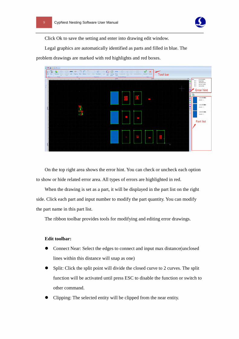
Click Ok to save the setting and enter into drawing edit window.
Legal graphics are automatically identified as parts and filled in blue. The
problem drawings are marked with red highlights and red boxes.
On the top right area shows the error hint. You can check or uncheck each option
to show or hide related error area. All types of errors are highlighted in red.
When the drawing is set as a part, it will be displayed in the part list on the right
side. Click each part and input number to modify the part quantity. You can modify
the part name in this part list.
The ribbon toolbar provides tools for modifying and editing error drawings.
Edit toolbar:
Connect Near: Select the edges to connect and input max distance(unclosed
lines within this distance will snap as one)
Split: Click the split point will divide the closed curve to 2 curves. The split
function will be activated until press ESC to disable the function or switch to
other command.
Clipping: The selected entity will be clipped from the near entity.
CypNest Nesting Software User Manual 10
Fillet: Add fillet corner to the graph entity.
Release: Add a release corner to the specified position.
Array: Array the selected graphic entities.
Transform toolbar:
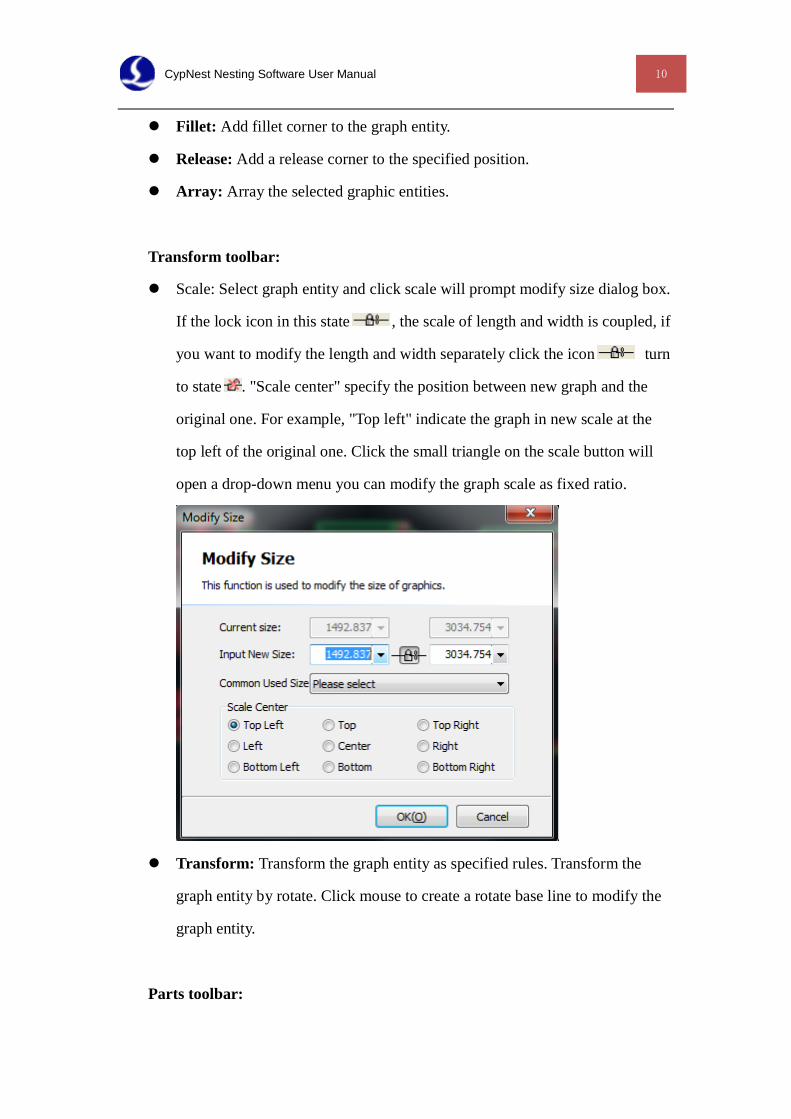
Scale: Select graph entity and click scale will prompt modify size dialog box.
If the lock icon in this state , the scale of length and width is coupled, if
you want to modify the length and width separately click the icon turn
to state . "Scale center" specify the position between new graph and the
original one. For example, "Top left" indicate the graph in new scale at the
top left of the original one. Click the small triangle on the scale button will
open a drop-down menu you can modify the graph scale as fixed ratio.
Transform: Transform the graph entity as specified rules. Transform the
graph entity by rotate. Click mouse to create a rotate base line to modify the
graph entity.
Parts toolbar:
11 CypNest Nesting Software User Manual
Regroup: Automatically analyze the drawings, graphic entities without
errors are automatically set as parts.
Set as parts: Set the selected graphic entity as a part, the wrong graphic
entity cannot be set as a part
Drawing toolbar on the left
Line: Click and drag to draw a straight line.
Rectangle: Drag a diagonal line to draw a rectangle.
Circle: Drag the mouse to draw a circle.
Polyline: Click mouse to create the control point of polyline, meanwhile you
can right click the mouse to switch the polyline type.
Node mode: Activate the node mode will display the nodes of selected
graphic entity. Drag the node to modify the node position.
Click Ok to save the setting, all the parts in list will be imported into nesting
page. All the graphical technique data will be saved with the parts.
2.2.2 Import from file
Add dxf file. If there is more than one part in the drawing, the software will
identify the part by inner and outer contour of the graphic. You can import bath files
in one time. The part name same with the file name. You can also input the new part
CypNest Nesting Software User Manual 12
name.
If software detected there is unclosed graph entity will prompt warning to show
the file name and won't add any process to the file.
2.3 Add sheet and sheet setting
In sheet list on the right side will display all the plan sheet and quantity. Click
to add sheet in the nesting list, select the sheet you can also manually nest the
parts on it.
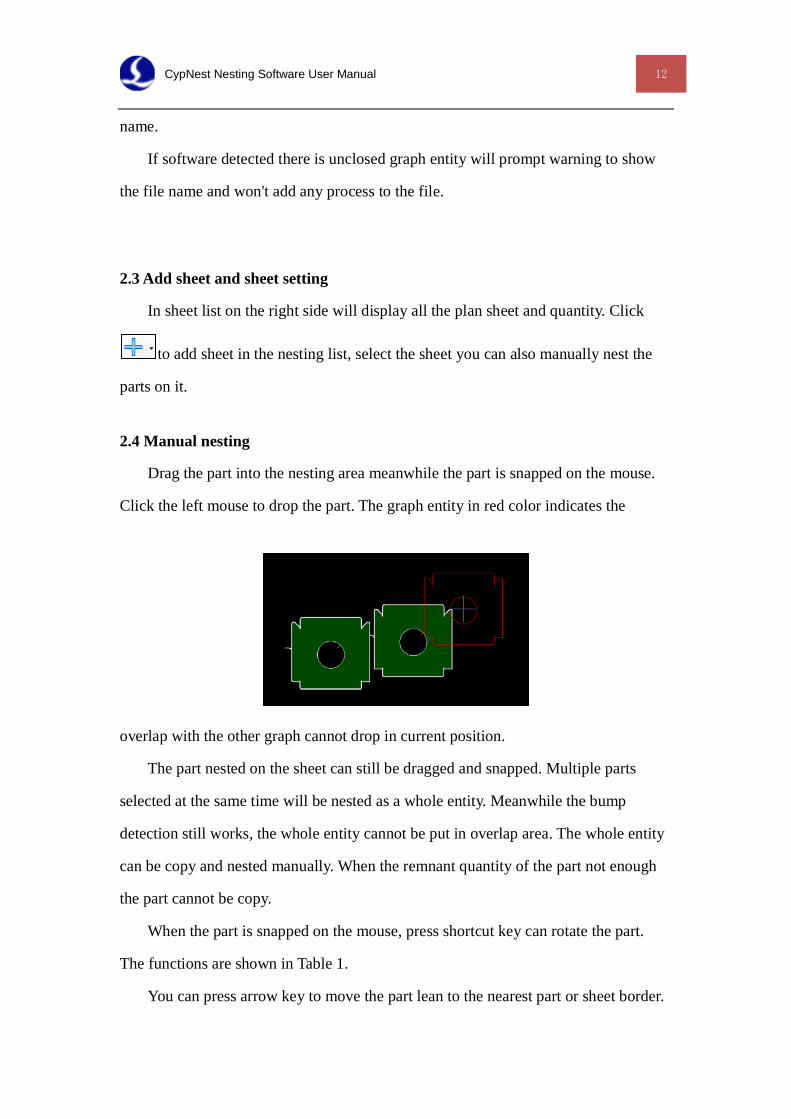
2.4 Manual nesting
Drag the part into the nesting area meanwhile the part is snapped on the mouse.
Click the left mouse to drop the part. The graph entity in red color indicates the
overlap with the other graph cannot drop in current position.
The part nested on the sheet can still be dragged and snapped. Multiple parts
selected at the same time will be nested as a whole entity. Meanwhile the bump
detection still works, the whole entity cannot be put in overlap area. The whole entity
can be copy and nested manually. When the remnant quantity of the part not enough
the part cannot be copy.
When the part is snapped on the mouse, press shortcut key can rotate the part.
The functions are shown in Table 1.
You can press arrow key to move the part lean to the nearest part or sheet border.
13 CypNest Nesting Software User Manual
Select a part and press array will open the array window. By "Dynamic Array"
you can drag the border box around the part to array the part. By "Array" you set the
parameter and create the array.
Also you can press shortcut key to finish the dynamic array and parameter array.
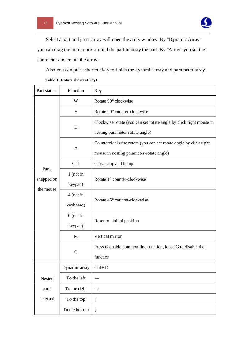
Table 1: Rotate shortcut key1
Part status Function Key
Parts
snapped on
the mouse
W Rotate 90° clockwise
S Rotate 90° counter-clockwise
D Clockwise rotate (you can set rotate angle by click right mouse in
nesting parameter-rotate angle)
A Counterclockwise rotate (you can set rotate angle by click right
mouse in nesting parameter-rotate angle)
Ctrl Close snap and bump
1 (not in
keypad) Rotate 1° counter-clockwise
4 (not in
keyboard) Rotate 45° counter-clockwise
0 (not in
keypad) Reset to initial position
M Vertical mirror
G Press G enable common line function, loose G to disable the
function
Nested
parts
selected
Dynamic array Ctrl+ D
To the left ←
To the right →
To the top ↑
To the bottom ↓
CypNest Nesting Software User Manual 14
By "Parts gap" in nest toolbar define the spacing between
the parts. This parameter can be modified anytime in nesting process.
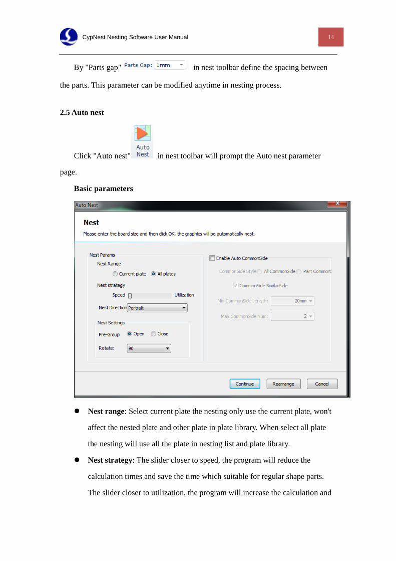
2.5 Auto nest
Click "Auto nest" in nest toolbar will prompt the Auto nest parameter
page.
Basic parameters
Nest range: Select current plate the nesting only use the current plate, won't
affect the nested plate and other plate in plate library. When select all plate
the nesting will use all the plate in nesting list and plate library.
Nest strategy: The slider closer to speed, the program will reduce the
calculation times and save the time which suitable for regular shape parts.
The slider closer to utilization, the program will increase the calculation and
15 CypNest Nesting Software User Manual
use the optimal solution, which suitable for the irregular shape parts.
Nest direction: The software will nest the parts in the selected direction.
Nest settings:
Pre group: Enable the function the program will nest the parts into
rectangular shape to improve the utilization. It's not suitable for parts of
arc shape.
Rotate: The parts will be rotated by the integral multiple of the degree.
Common line
Activate the function the program will snap the edges of the parts according to
the setting.
Common line type: Select "All common line", as long as the snap edges reach
to the min common line length will be merged as common line. It's not
recommended to use all common line, it might sacrifice the cutting quality. Select
part common line, the common line part cannot exceed the max common line
number. Select common line similar side, only similar parts edges will be
merged as common line.
Click continue will resume nesting and keep the current nest result. Select
"rearrange" the program will clear nest result and restart nesting. If the parts not
nested yet just click start nest.
CypNest Nesting Software User Manual 16
Chapter 3 Common line tool path
The program designed common line array for the regular rectangle shape part.
After array the parts the program will create the tool path automatically. The parts
nested manually in common line will have to sort the sequence then create the tool
path.
3.1 Common line array
You can nest the part by common line array and no need to create tool path. This
is efficient for the regular rectangle parts nesting.
There are three ways to generate tool path of common line array.
3.1.1 Common line first
The tool path is designed for “目”shape array, all the common line are parallel in
same length.
The tool path of this pattern is cutting common line first then the outer frame.
Add joint at the cross section between common line and outer frame to prevent tip-up
crash.
17 CypNest Nesting Software User Manual
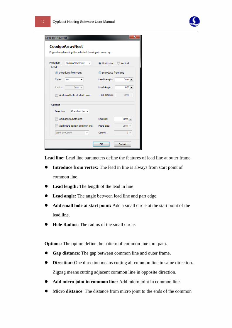
Lead line: Lead line parameters define the features of lead line at outer frame.
Introduce from vertex: The lead in line is always from start point of
common line.
Lead length: The length of the lead in line
Lead angle: The angle between lead line and part edge.
Add small hole at start point: Add a small circle at the start point of the
lead line.
Hole Radius: The radius of the small circle.
Options: The option define the pattern of common line tool path.
Gap distance: The gap between common line and outer frame.
Direction: One direction means cutting all common line in same direction.
Zigzag means cutting adjacent common line in opposite direction.
Add micro joint in common line: Add micro joint in common line.
Micro distance: The distance from micro joint to the ends of the common
CypNest Nesting Software User Manual 18
line.
Micro size: The length of the micro joint.
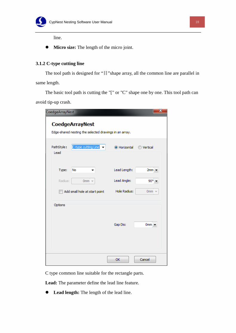
3.1.2 C-type cutting line
The tool path is designed for “目”shape array, all the common line are parallel in
same length.
The basic tool path is cutting the "[" or "C" shape one by one. This tool path can
avoid tip-up crash.
C type common line suitable for the rectangle parts.
Lead: The parameter define the lead line feature.
Lead length: The length of the lead line.
19 CypNest Nesting Software User Manual
Lead angle: Angle between lead line and part edge.
Add small hole at start point: Add a small circle at the start point of the
lead line.
Hole Radius: The radius of the small circle.
Options: The option define the pattern of common line tool path.
Gap distance: The joint on a graphic entity at start point.
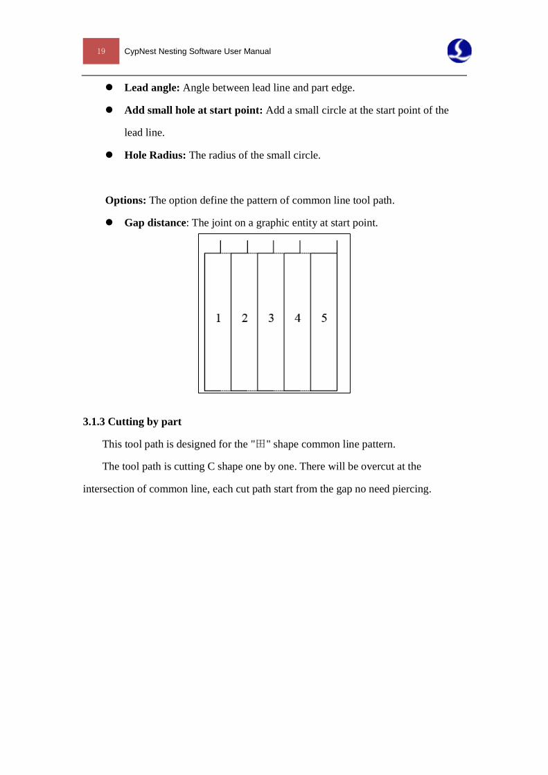
3.1.3 Cutting by part
This tool path is designed for the "田" shape common line pattern.
The tool path is cutting C shape one by one. There will be overcut at the
intersection of common line, each cut path start from the gap no need piercing.
CypNest Nesting Software User Manual 20
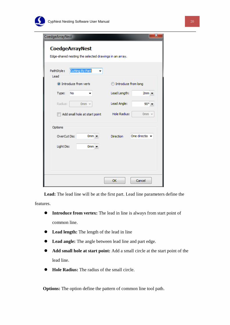
Lead: The lead line will be at the first part. Lead line parameters define the
features.
Introduce from vertex: The lead in line is always from start point of
common line.
Lead length: The length of the lead in line
Lead angle: The angle between lead line and part edge.
Add small hole at start point: Add a small circle at the start point of the
lead line.
Hole Radius: The radius of the small circle.
Options: The option define the pattern of common line tool path.
21 CypNest Nesting Software User Manual
Overcut distance: The overcut distance from the vertex of the common line
to the next part.
Direction: Cutting sequence of array parts. Zigzag means cutting path is S
shape, one direction means same cutting direction to all parts.
Light distance: The distance from laser fires to the overcut point.
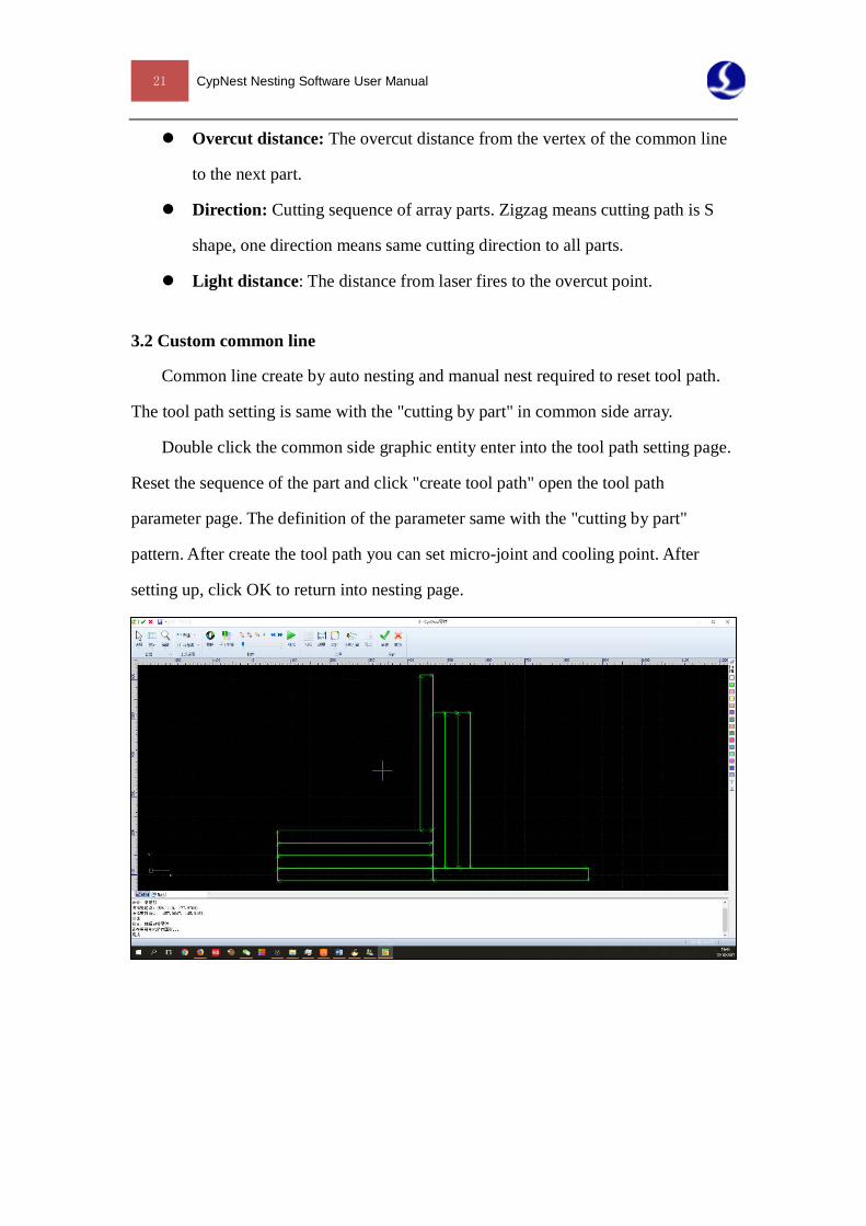
3.2 Custom common line
Common line create by auto nesting and manual nest required to reset tool path.
The tool path setting is same with the "cutting by part" in common side array.
Double click the common side graphic entity enter into the tool path setting page.
Reset the sequence of the part and click "create tool path" open the tool path
parameter page. The definition of the parameter same with the "cutting by part"
pattern. After create the tool path you can set micro-joint and cooling point. After
setting up, click OK to return into nesting page.
CypNest Nesting Software User Manual 22
Chapter 4 Processing settings
4.1 Graphic technique settings
After nested the parts you can modify the nesting result by technical parameter
tool bar. The operation is same with that of CypCut software.
4.2 Batch modification
The technique of same part can be batch modified. Including start point, micro
joint and cooling point.
Click each technique option the modify range will show in the left bar.
Current part: The modification only take effect on the current selected parts.
All parts: For example, the modification of Part A will take effect to all part A.
Same rotating: The modification of part A will take effect to all the parts A same
angle with current selected one.
Select manually: Frame select the parts. The modification of part A will take
effect to all the part A selected.
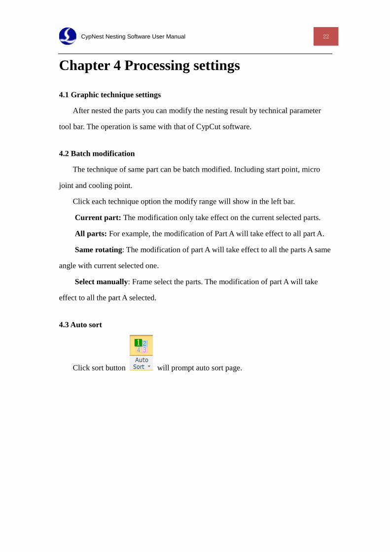
4.3 Auto sort
Click sort button will prompt auto sort page.
23 CypNest Nesting Software User Manual
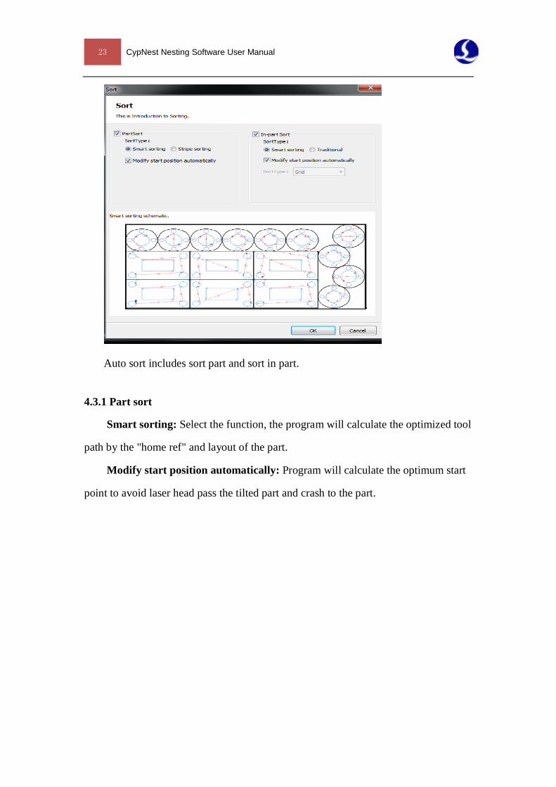
Auto sort includes sort part and sort in part.
4.3.1 Part sort
Smart sorting: Select the function, the program will calculate the optimized tool
path by the "home ref" and layout of the part.
Modify start position automatically: Program will calculate the optimum start
point to avoid laser head pass the tilted part and crash to the part.
CypNest Nesting Software User Manual 24
4.4 Manual sort:
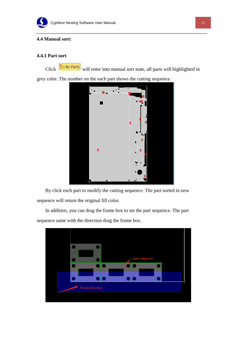
4.4.1 Part sort
Click will enter into manual sort state, all parts will highlighted in
grey color. The number on the each part shows the cutting sequence.
By click each part to modify the cutting sequence. The part sorted in new
sequence will return the original fill color.
In addition, you can drag the frame box to set the part sequence. The part
sequence same with the direction drag the frame box.
25 CypNest Nesting Software User Manual
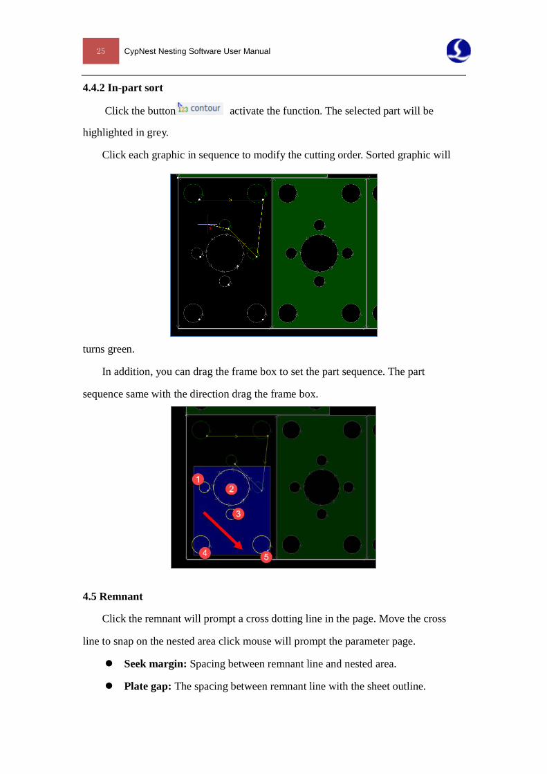
4.4.2 In-part sort
Click the button activate the function. The selected part will be
highlighted in grey.
Click each graphic in sequence to modify the cutting order. Sorted graphic will
turns green.
In addition, you can drag the frame box to set the part sequence. The part
sequence same with the direction drag the frame box.
4.5 Remnant
Click the remnant will prompt a cross dotting line in the page. Move the cross
line to snap on the nested area click mouse will prompt the parameter page.
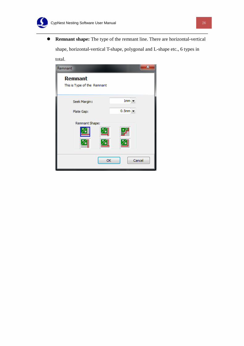
Seek margin: Spacing between remnant line and nested area.
Plate gap: The spacing between remnant line with the sheet outline.
CypNest Nesting Software User Manual 26
Remnant shape: The type of the remnant line. There are horizontal-vertical
shape, horizontal-vertical T-shape, polygonal and L-shape etc., 6 types in
total.
27 CypNest Nesting Software User Manual
Chapter 5 Export cutting file
5.1 Report
Click will prompt the parameter page. CypNest generates PDF and Excel
format nesting report.
Report name: File name of the report
Report type: Report format.
Content: To select the content generated in report. When PDF format is selected,
the price report will be generated separately.
Content options:
Show part list: Display the parts list in the report.
Plate size: Select "Plate" the plate dimension in report calculated by the pre-set
dimension;
Contour: Select “Contour” the plate dimension in report calculated by the
peripheral contour of the nesting area on the sheet.
Price parameters: It is used to calculate the material weight and cost in the price
report.
Save path: The save path of the report file.
The nesting report contains 3 part including task info, part list and work report.
Make sure the motion parameter is same with the actual cutting parameter, otherwise
the time count will be wrong.
Task information includes sheet metal overview and price information. The sheet
overview shows the sheet dimension, the utilization of the sheet, the processing time
and the unit price. And the price information shows the price estimator of the whole
processing task.
The part list shows the number, sequence and process quantity of each part.
CypNest Nesting Software User Manual 28
The processing report shows the nesting thumbnails and each part with number
on it for picking out the part easily. In addition, the production price for a single sheet,
production parameter and part list contained in the work report.
5.2 Export cutting file
CypNest software can generate files of 2 format- nrp file of nesting sheet package
and lxd.
Click the "export cutting file" will generate one nrp file contains all the
nesting sheet and can be read in CypCut as whole. Now only Cypcut 6.3.712.6 and
later support the function.
Select single nesting sheet can be saved as lxd file. Select a folder and all the
selected nesting sheet will be saved in the folder as lxd for importing in CypCut for
processing.
All the cutting parameters set in CypNest will be saved on the file and read by
CypCut.