Embed Size (px)
Citation preview
1
Data Link Layer
Lesson 6NETS2150/2850
2
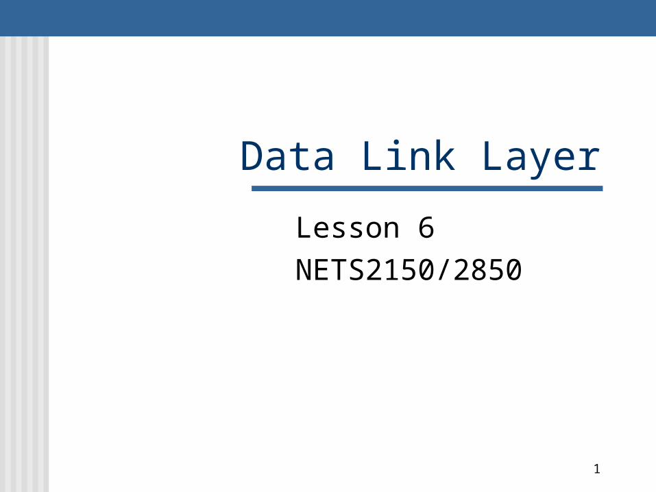
Position of the data-link layer
McGraw-Hill ©The McGraw-Hill Companies, Inc., 2004
3
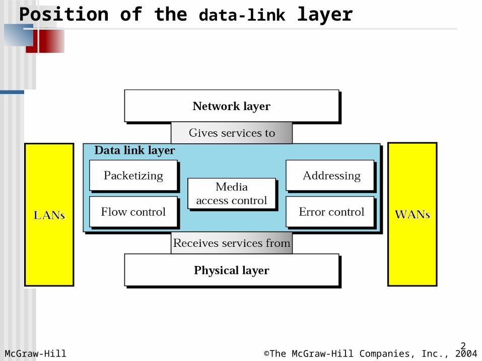
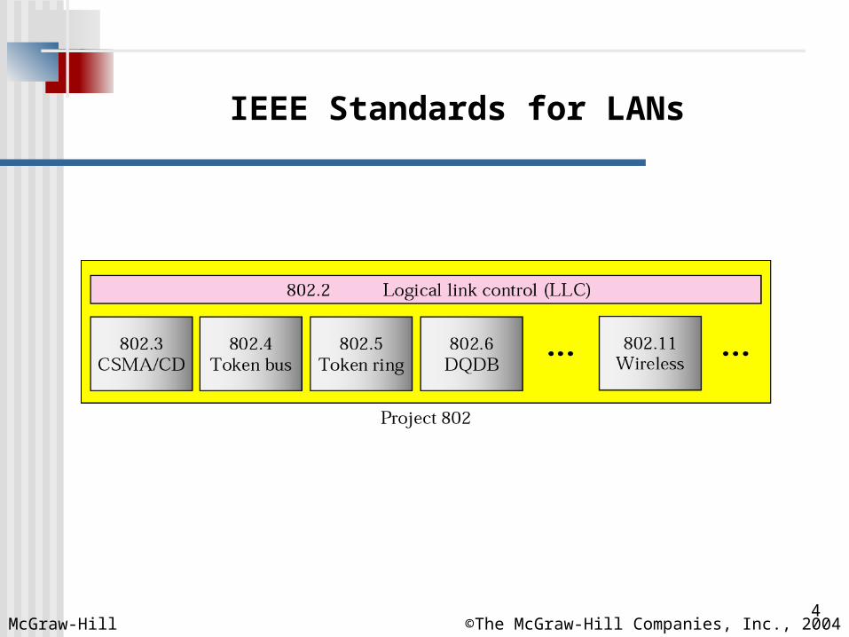
LLC and MAC sublayers
McGraw-Hill ©The McGraw-Hill Companies, Inc., 2004
4
IEEE Standards for LANs
McGraw-Hill ©The McGraw-Hill Companies, Inc., 2004
5
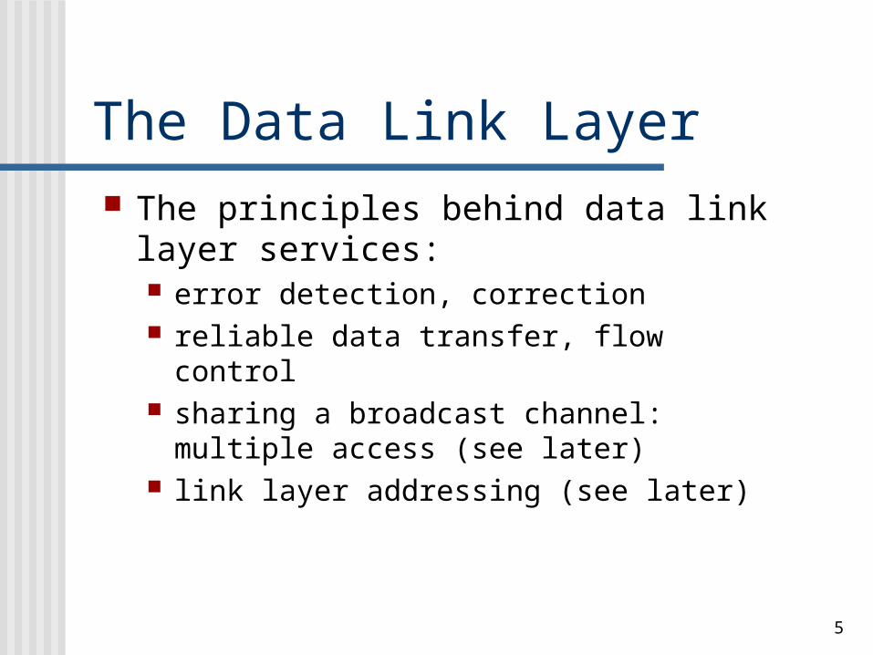
The Data Link Layer The principles behind data link layer
services: error detection, correction reliable data transfer, flow control sharing a broadcast channel: multiple
access (see later) link layer addressing (see later)
6
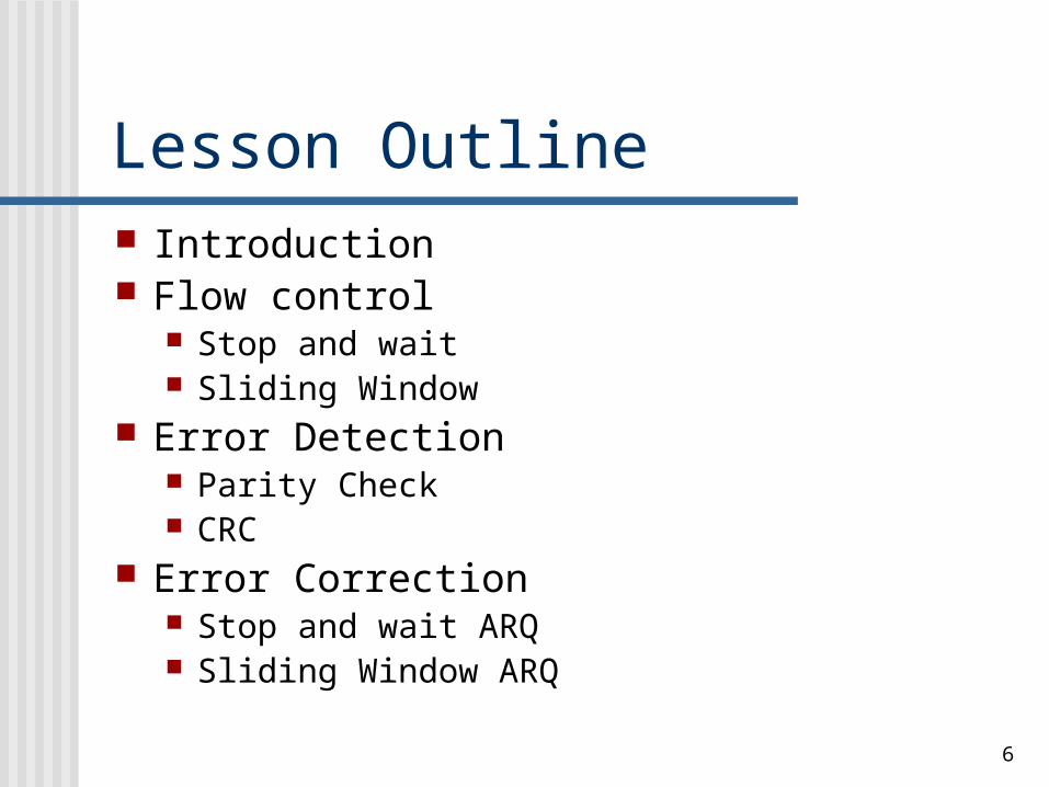
Lesson Outline Introduction Flow control
Stop and wait Sliding Window
Error Detection Parity Check CRC
Error Correction Stop and wait ARQ Sliding Window ARQ
7
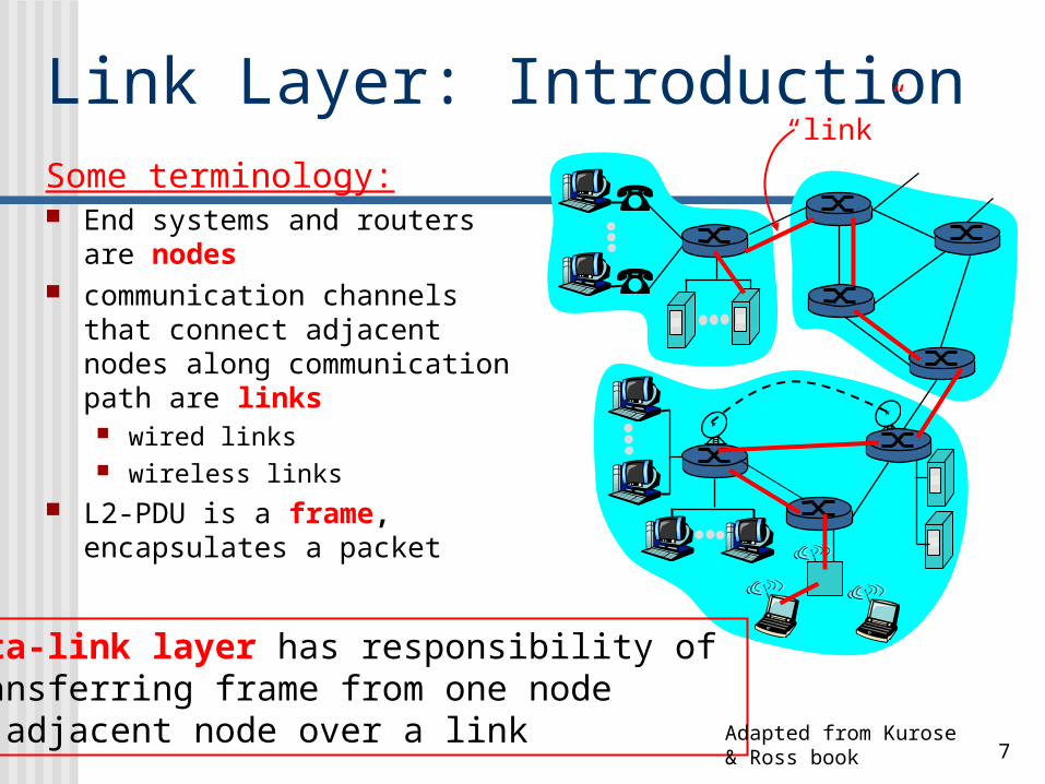
Link Layer: IntroductionSome terminology: End systems and routers are
nodes communication channels
that connect adjacent nodes along communication path are links wired links wireless links
L2-PDU is a frame, encapsulates a packet
“link”
data-link layer has responsibility of transferring frame from one node to adjacent node over a link Adapted from Kurose &
Ross book
8
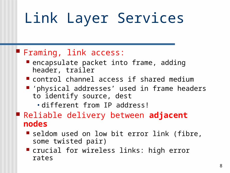
Link Layer Services
Framing, link access: encapsulate packet into frame, adding
header, trailer control channel access if shared medium ‘physical addresses’ used in frame headers
to identify source, dest • different from IP address!
Reliable delivery between adjacent nodes seldom used on low bit error link (fibre,
some twisted pair) crucial for wireless links: high error rates
9
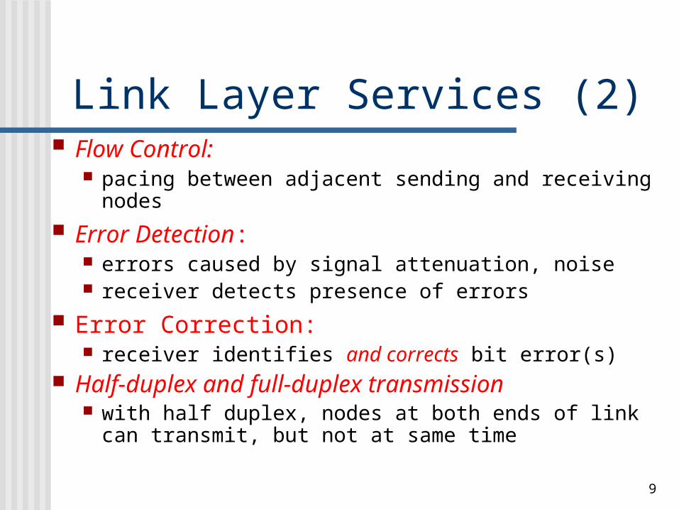
Link Layer Services (2) Flow Control:
pacing between adjacent sending and receiving nodes
Error Detection: errors caused by signal attenuation, noise receiver detects presence of errors
Error Correction: receiver identifies and corrects bit error(s)
Half-duplex and full-duplex transmission with half duplex, nodes at both ends of link can
transmit, but not at same time
10
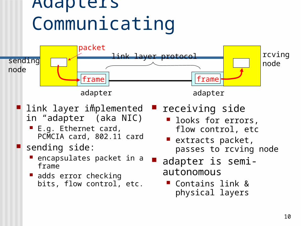
Adapters Communicating
link layer implemented in “adapter” (aka NIC) E.g. Ethernet card,
PCMCIA card, 802.11 card
sending side: encapsulates packet in a
frame adds error checking bits,
flow control, etc.
receiving side looks for errors, flow
control, etc extracts packet, passes
to rcving node adapter is semi-
autonomous Contains link & physical
layers
sendingnode
frame
rcvingnode
packet
frame
adapter adapter
link layer protocol
11
Flow control refers to a set of Flow control refers to a set of procedures used to restrict the amount procedures used to restrict the amount of data that the sender can send before of data that the sender can send before
waiting for acknowledgmentwaiting for acknowledgment
McGraw-Hill ©The McGraw-Hill Companies, Inc., 2004
12
Flow Control Ensuring the sending entity does not
overwhelm the receiving entity Preventing buffer overflow
Two schemes: Stop and Wait Sliding Window
13
Stop and Wait Source transmits frame Destination receives frame and
replies with acknowledgement Source waits for ACK before sending
next frame Destination can stop flow by not
send ACK Works well for a few large frames
14
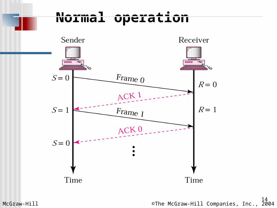
Normal operation
McGraw-Hill ©The McGraw-Hill Companies, Inc., 2004
15
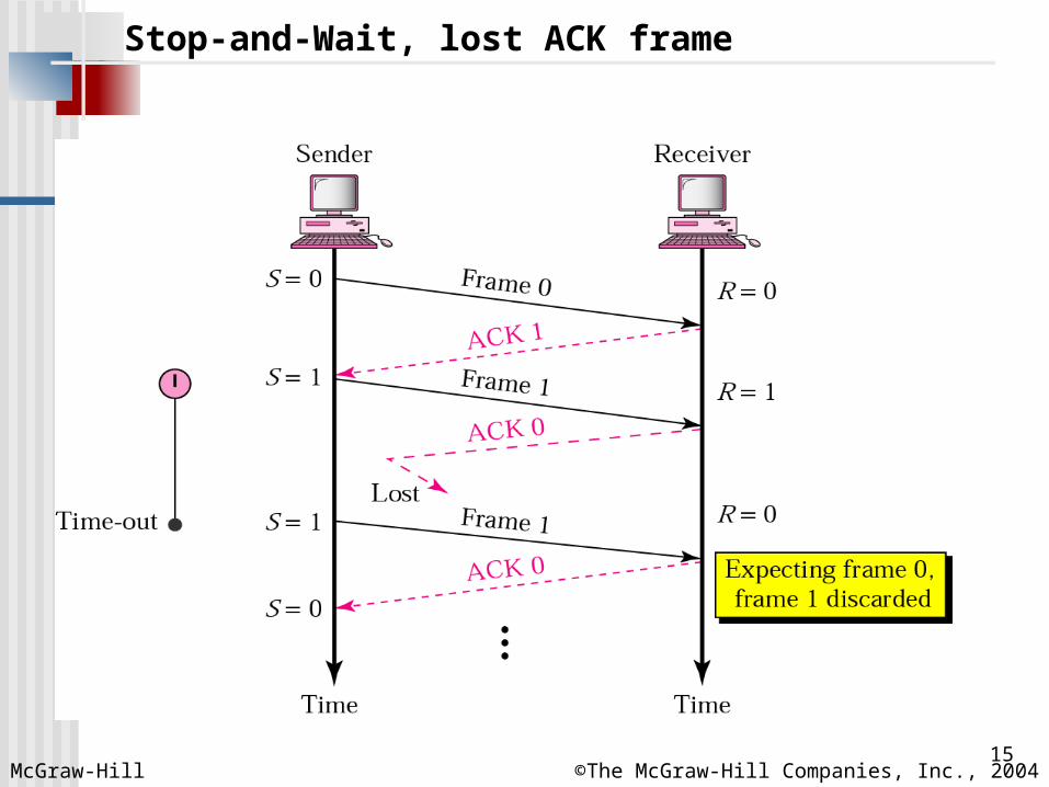
Stop-and-Wait, lost ACK frame
McGraw-Hill ©The McGraw-Hill Companies, Inc., 2004
16
Numbering frames prevents the Numbering frames prevents the retaining of duplicate framesretaining of duplicate frames
McGraw-Hill ©The McGraw-Hill Companies, Inc., 2004
17
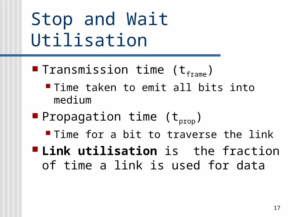
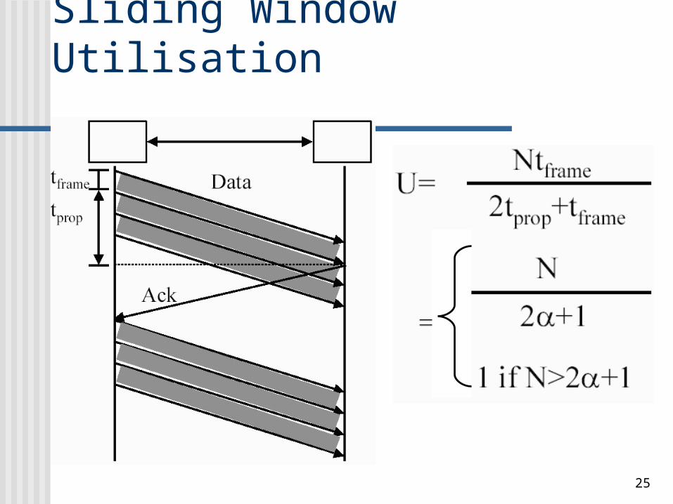
Stop and Wait Utilisation
Transmission time (tframe) Time taken to emit all bits into medium
Propagation time (tprop) Time for a bit to traverse the link
Link utilisation is the fraction of time a link is used for data
18
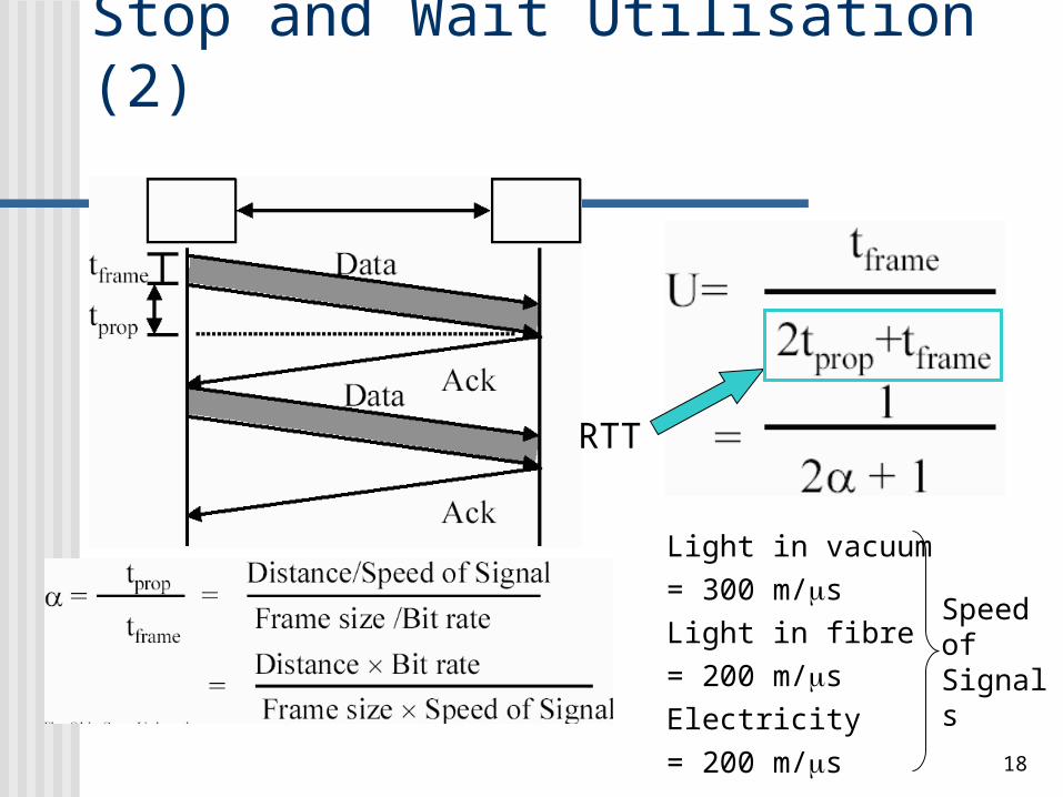
Stop and Wait Utilisation (2)
Light in vacuum
= 300 m/s
Light in fibre
= 200 m/s
Electricity
= 200 m/s
Speed of Signals
RTT
19
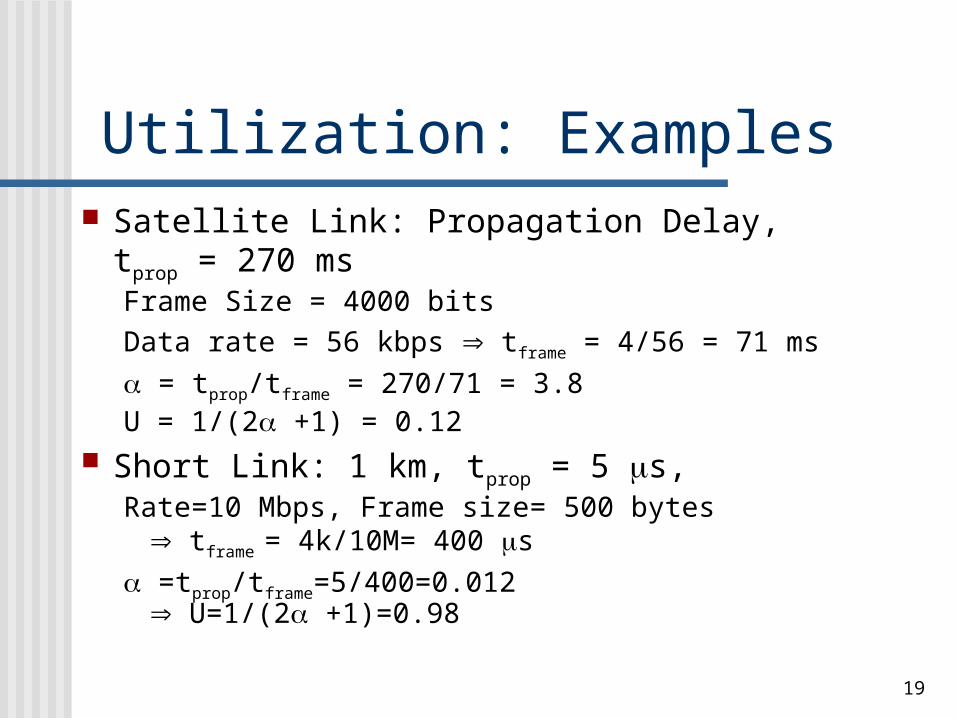
Utilization: Examples Satellite Link: Propagation Delay,
tprop = 270 msFrame Size = 4000 bitsData rate = 56 kbps tframe = 4/56 = 71 ms
= tprop/tframe = 270/71 = 3.8U = 1/(2 +1) = 0.12
Short Link: 1 km, tprop = 5 s,Rate=10 Mbps, Frame size= 500 bytes
tframe = 4k/10M= 400 s
=tprop/tframe=5/400=0.012 U=1/(2 +1)=0.98
20
Fragmentation Large block of data may be split into small
frames. Why? Limited buffer size at rcvr Errors can be detected sooner On error, only retransmission of smaller
frames is needed Prevents one station occupying medium for
long periods However, stop and wait is inadequate to
cater for long-delay links!!
21
Sliding Window Flow Control Allow multiple frames to be in transit Receiver has buffer W-frame long Transmitter can send up to W frames without
ACK Each frame is numbered ACK includes number of next frame expected Sequence number bounded by size of
sequence # field (k-bit) Frames are numbered modulo 2k
Max window size 2k - 1
22
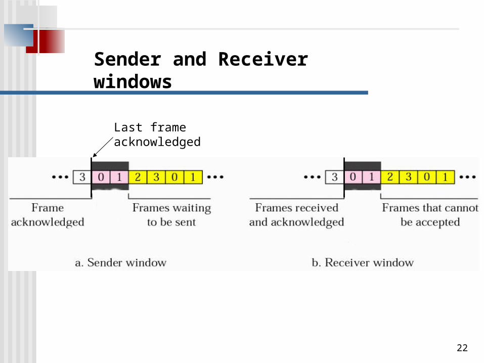
Sender and Receiver windows
Last frame acknowledged
23
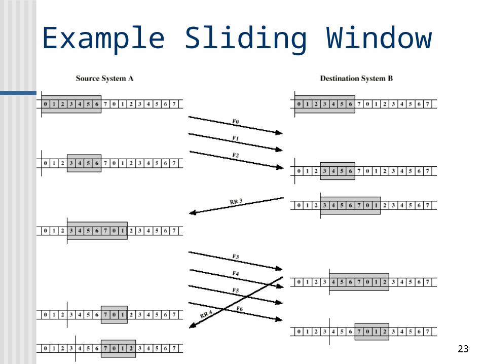
Example Sliding Window
24
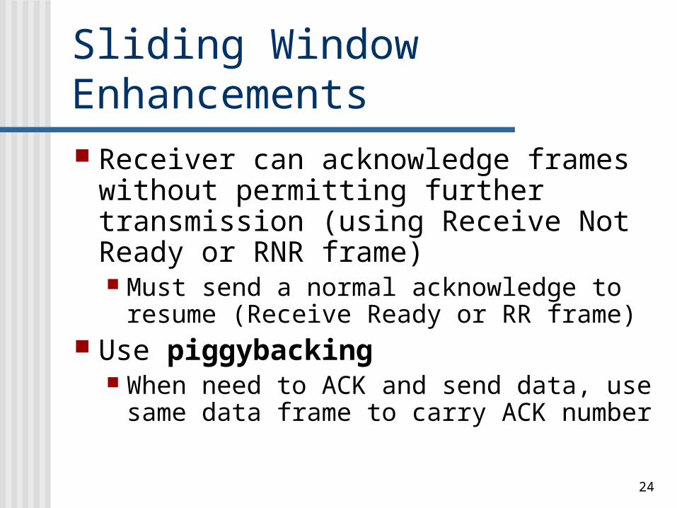
Sliding Window Enhancements Receiver can acknowledge frames
without permitting further transmission (using Receive Not Ready or RNR frame) Must send a normal acknowledge to
resume (Receive Ready or RR frame) Use piggybacking
When need to ACK and send data, use same data frame to carry ACK number
25
Sliding Window Utilisation
26
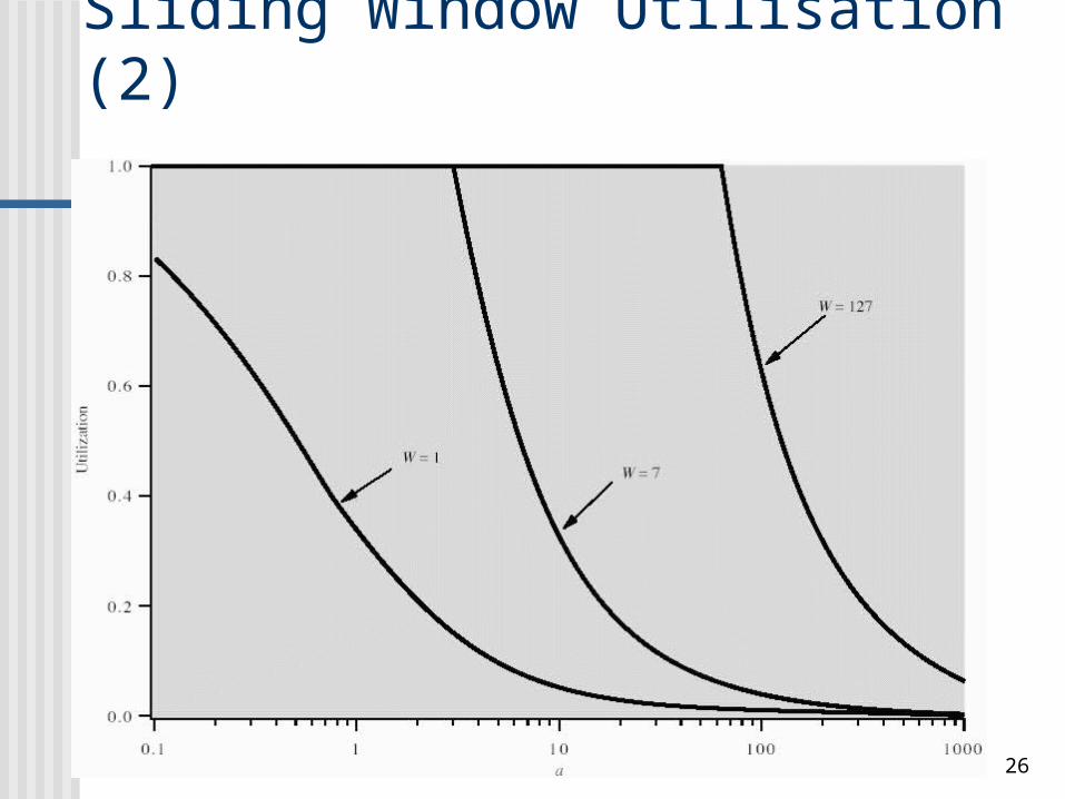
Sliding Window Utilisation (2)
27
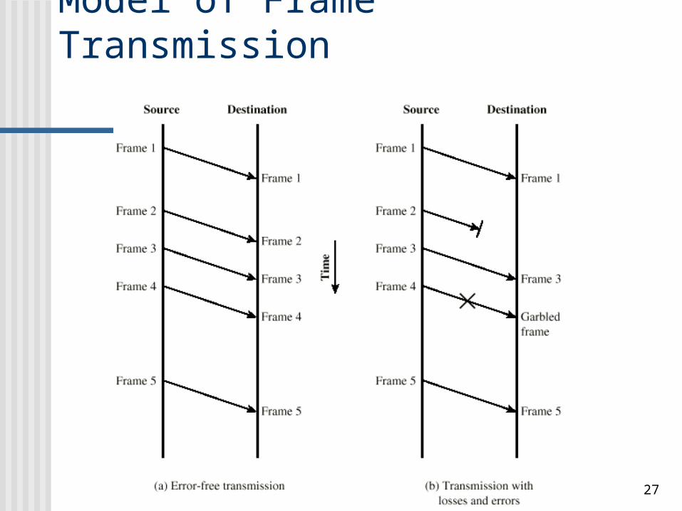
Model of Frame Transmission
28
Data can be corrupted during transmission. For reliable
communication, errors must be detected and corrected.
29
Types of ErrorTypes of Error
Single-Bit Error
Burst Error
30
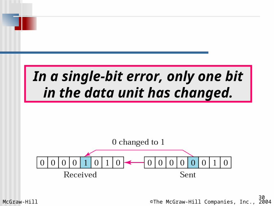
In a single-bit error, only one bit in the data unit has changed.
McGraw-Hill ©The McGraw-Hill Companies, Inc., 2004
31McGraw-Hill ©The McGraw-Hill Companies, Inc., 2004
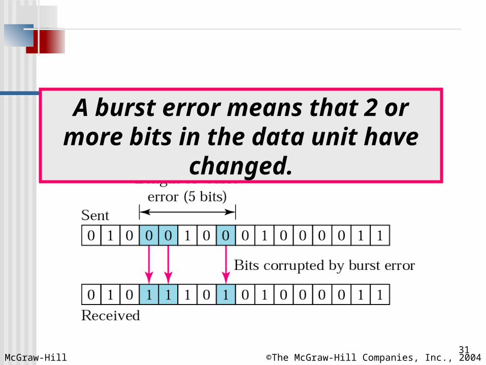
A burst error means that 2 or more bits in the data unit have changed.
32
Error Detection MethodsError Detection Methods
Parity Check
Cyclic Redundancy Check (CRC)
Checksum (see later)
33McGraw-Hill ©The McGraw-Hill Companies, Inc., 2004
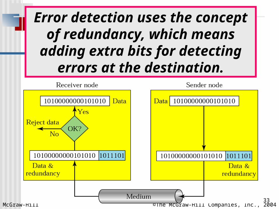
Error detection uses the concept of redundancy, which means adding
extra bits for detecting errors at the destination.
34
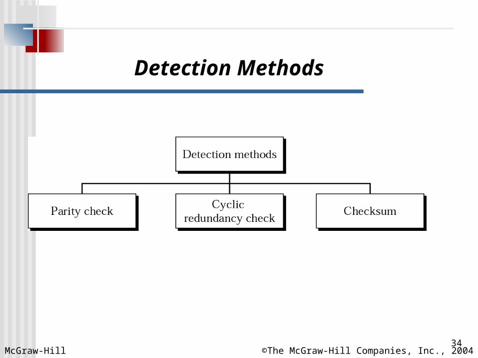
Detection Methods
McGraw-Hill ©The McGraw-Hill Companies, Inc., 2004
35
In even parity check, a parity bit is added to every data unit so that the
total number of 1s is even (or odd for odd-parity).
36
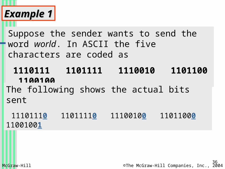
Example 1Example 1
Suppose the sender wants to send the word world. In ASCII the five characters are coded as
1110111 1101111 1110010 1101100 1100100
The following shows the actual bits sent
11101110 11011110 11100100 11011000 11001001
McGraw-Hill ©The McGraw-Hill Companies, Inc., 2004
37
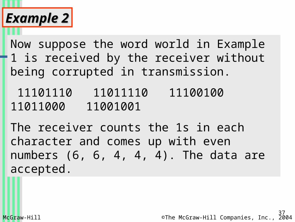
Example 2Example 2
Now suppose the word world in Example 1 is received by the receiver without being corrupted in transmission.
11101110 11011110 11100100 11011000 11001001
The receiver counts the 1s in each character and comes up with even numbers (6, 6, 4, 4, 4). The data are accepted.
McGraw-Hill ©The McGraw-Hill Companies, Inc., 2004
38
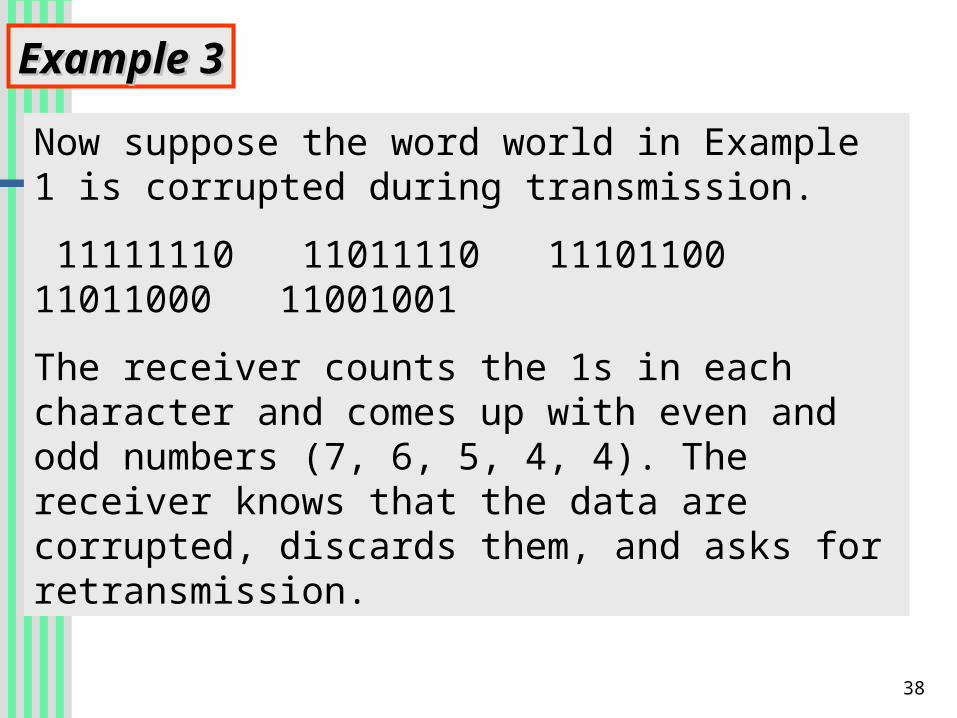
Example 3Example 3
Now suppose the word world in Example 1 is corrupted during transmission.
11111110 11011110 11101100 11011000 11001001
The receiver counts the 1s in each character and comes up with even and odd numbers (7, 6, 5, 4, 4). The receiver knows that the data are corrupted, discards them, and asks for retransmission.
39
Simple parity check can detect all Simple parity check can detect all single-bit errors. It can detect burst single-bit errors. It can detect burst errors only if the total number of errors only if the total number of errors in each data unit is odd.errors in each data unit is odd.
Even number of bit errors goes Even number of bit errors goes undetected!undetected!
40
In two-dimensional parity check, a block of bits is divided into rows and a redundant row of bits is added to the
whole block.
41
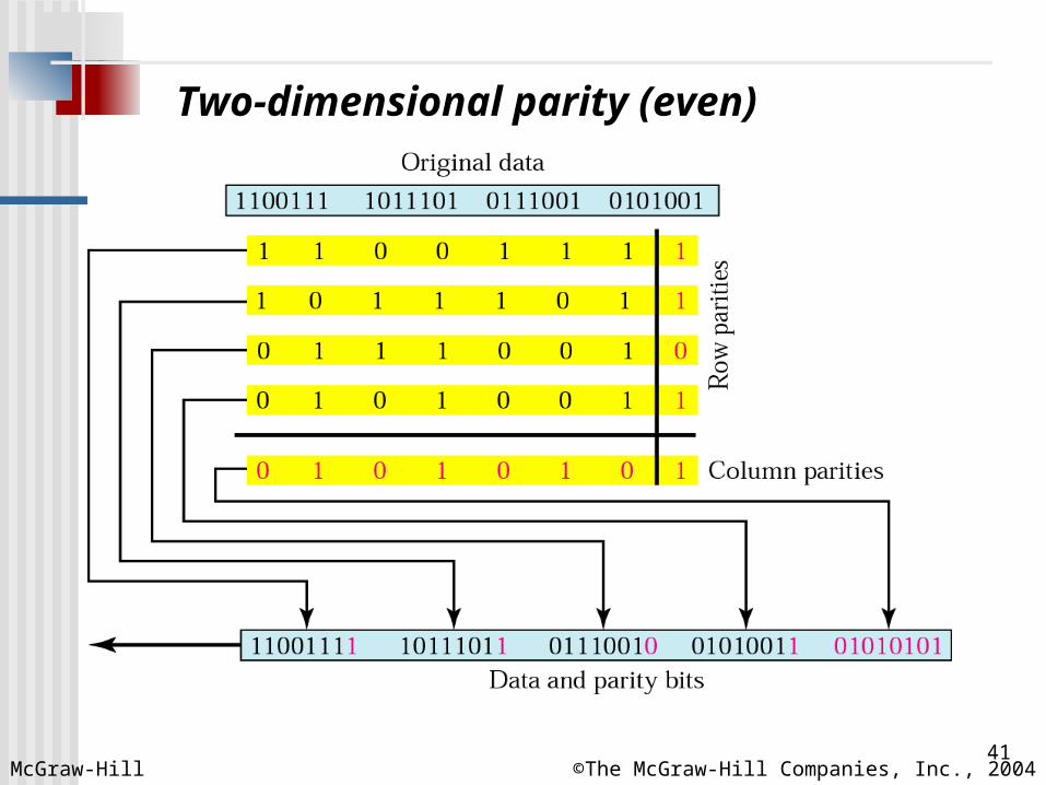
Two-dimensional parity (even)
McGraw-Hill ©The McGraw-Hill Companies, Inc., 2004
42
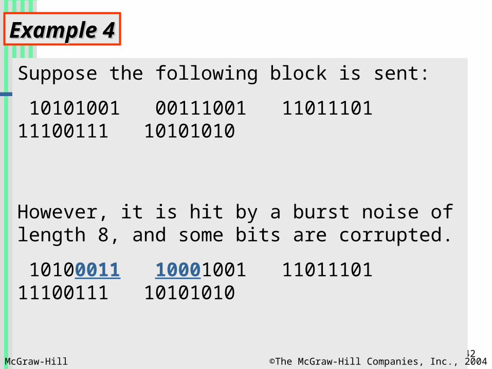
Example 4Example 4
Suppose the following block is sent:
10101001 00111001 11011101 11100111 10101010
However, it is hit by a burst noise of length 8, and some bits are corrupted.
10100011 10001001 11011101 11100111 10101010
When the receiver checks the parity bits, some of the bits do not follow the even-parity rule and the whole block is discarded.
10100011 10001001 11011101 11100111 10101010
McGraw-Hill ©The McGraw-Hill Companies, Inc., 2004
43
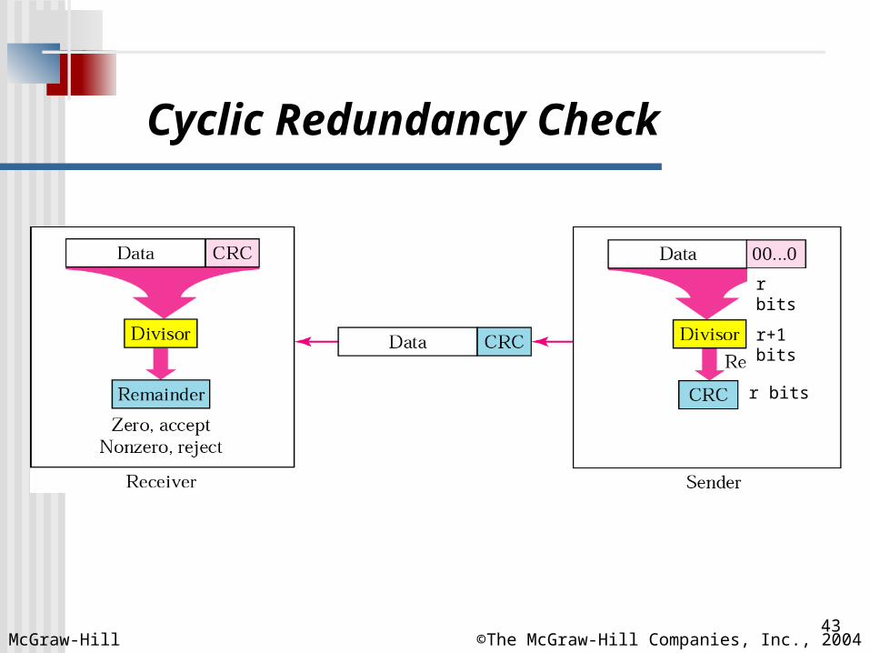
Cyclic Redundancy Check
McGraw-Hill ©The McGraw-Hill Companies, Inc., 2004
r bits
r+1 bits
r bits
44
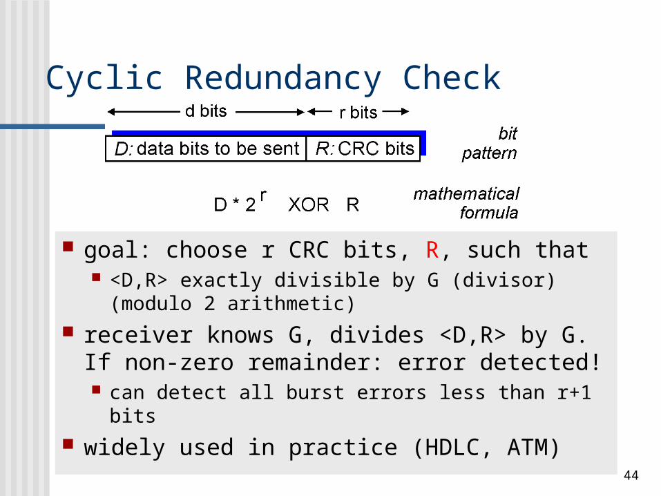
Cyclic Redundancy Check
goal: choose r CRC bits, R, such that <D,R> exactly divisible by G (divisor)
(modulo 2 arithmetic) receiver knows G, divides <D,R> by G.
If non-zero remainder: error detected! can detect all burst errors less than r+1 bits
widely used in practice (HDLC, ATM)
45
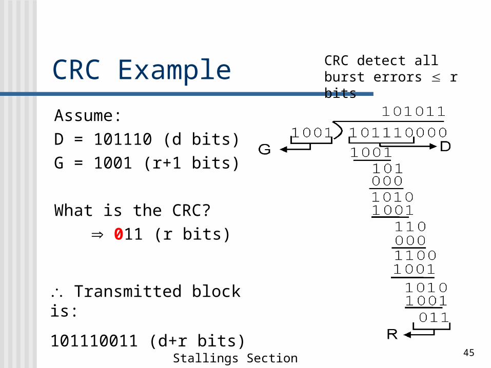
CRC Example
Assume:D = 101110 (d bits)G = 1001 (r+1 bits)
What is the CRC?
Transmitted block is:
101110011 (d+r bits)
011 (r bits)
Stallings Section 6.3
CRC detect all burst errors r bits
46
Error Control Deliver frames without error, in the
proper order to network layer Handles Lost frames
And damaged frames An automatic repeat request scheme:
Error detection Positive acknowledgment Retransmission after timeout Negative acknowledgement and
retransmission
47
Automatic Repeat Request (ARQ) Stop and wait ARQ Sliding window schemes
Go back N ARQ Selective reject (selective repeat) ARQ
48
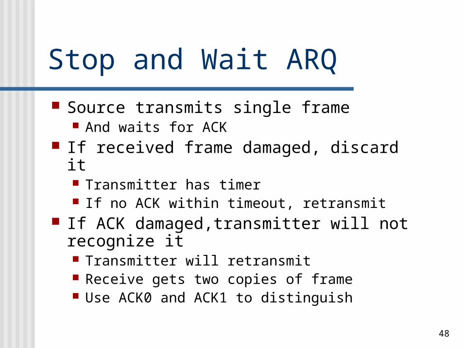
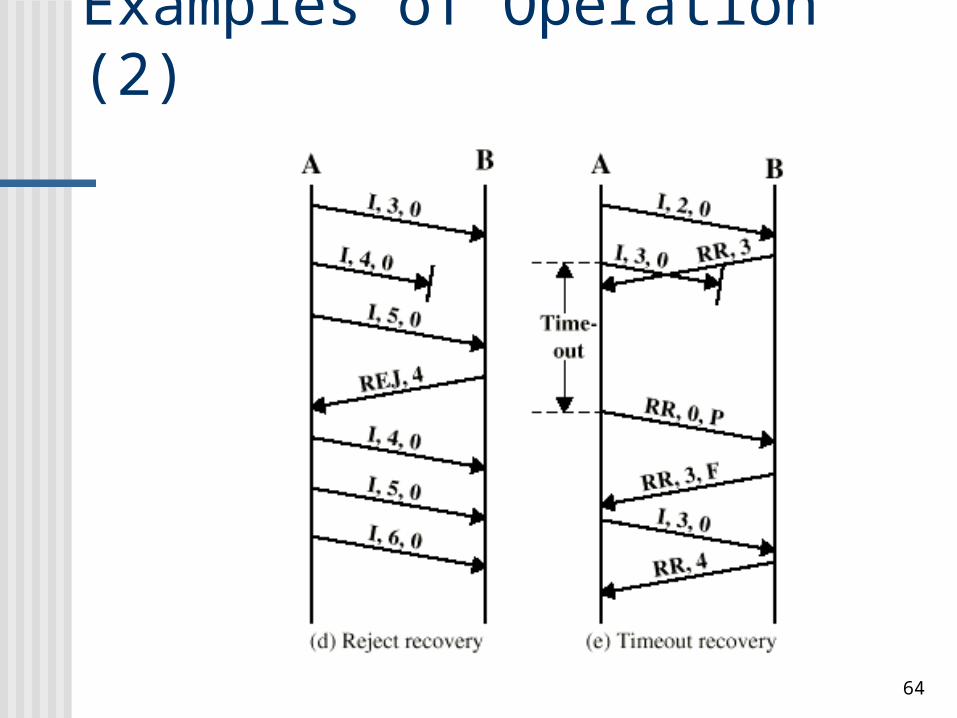
Stop and Wait ARQ
Source transmits single frame And waits for ACK
If received frame damaged, discard it Transmitter has timer If no ACK within timeout, retransmit
If ACK damaged,transmitter will not recognize it Transmitter will retransmit Receive gets two copies of frame Use ACK0 and ACK1 to distinguish
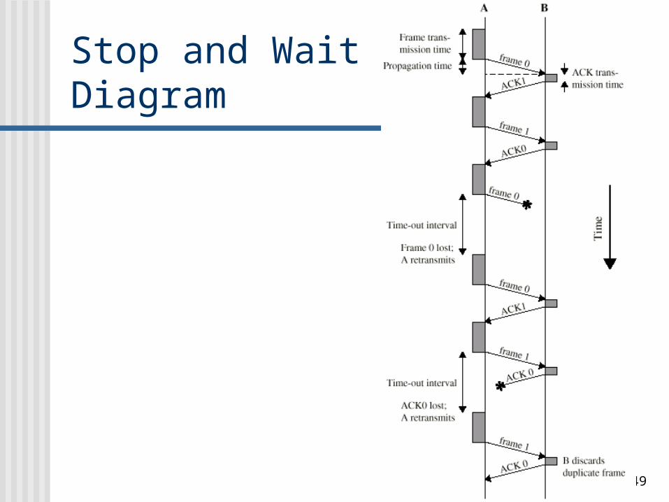
49
Stop and Wait -Diagram
50
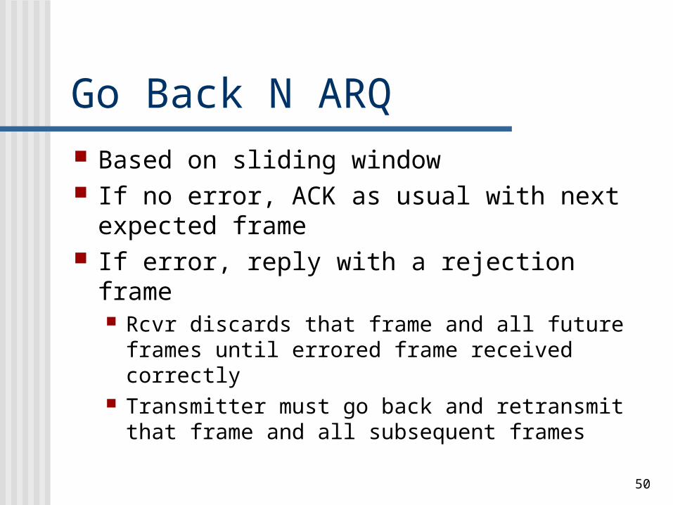
Go Back N ARQ Based on sliding window If no error, ACK as usual with next
expected frame If error, reply with a rejection frame
Rcvr discards that frame and all future frames until errored frame received correctly
Transmitter must go back and retransmit that frame and all subsequent frames
51
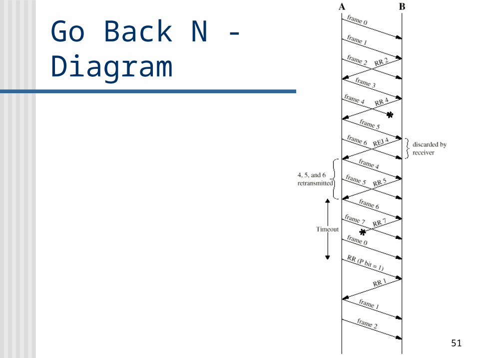
Go Back N - Diagram
52
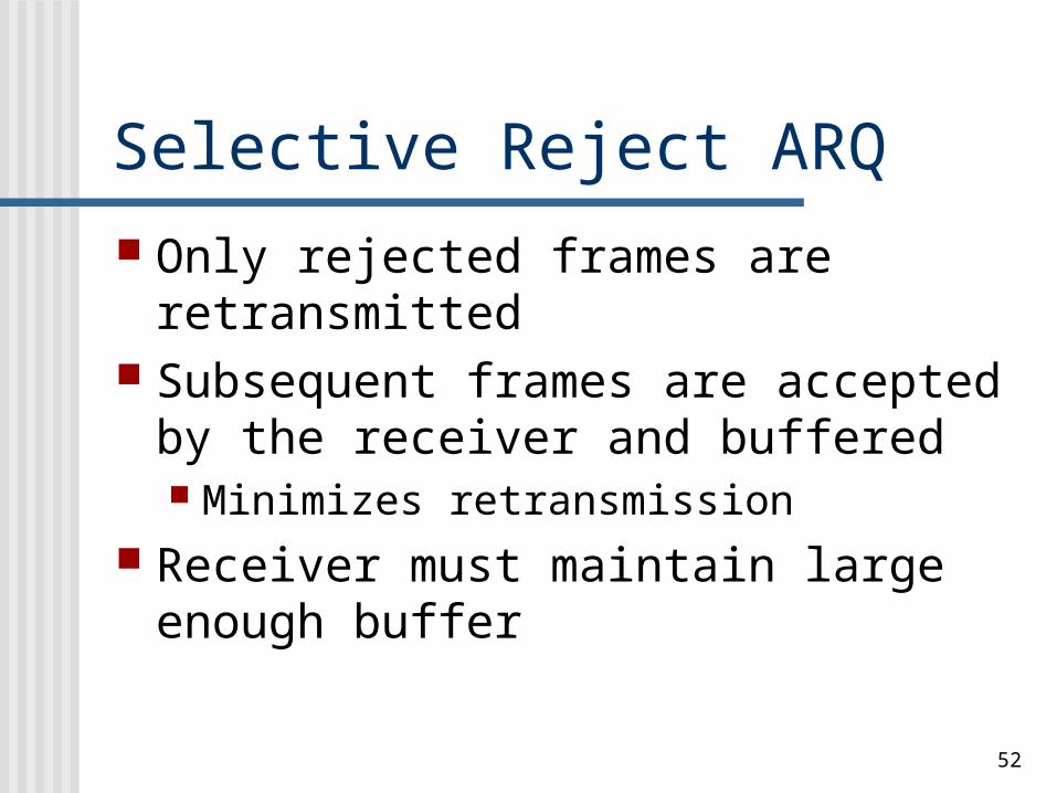
Selective Reject ARQ Only rejected frames are
retransmitted Subsequent frames are accepted by
the receiver and buffered Minimizes retransmission
Receiver must maintain large enough buffer
53
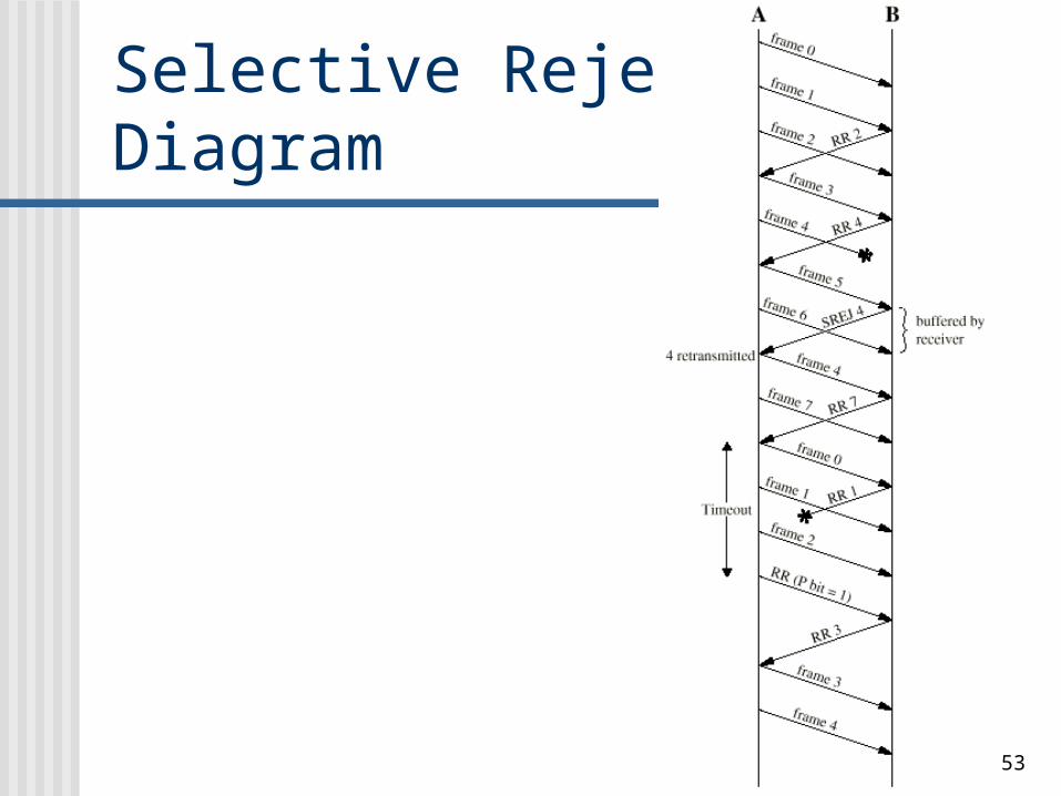
Selective Reject -Diagram
54
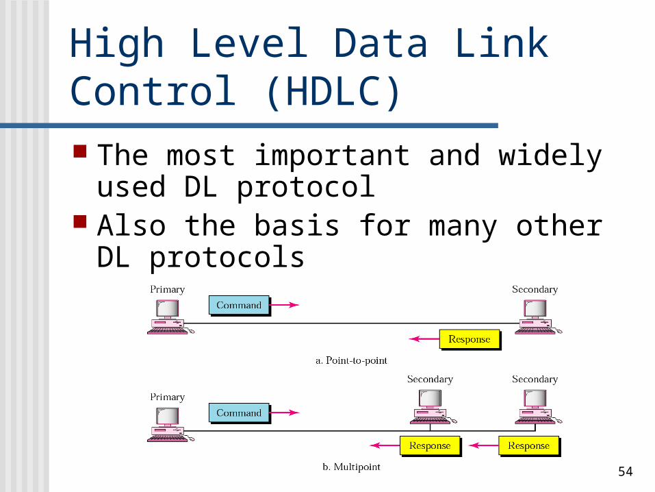
High Level Data Link Control (HDLC) The most important and widely
used DL protocol Also the basis for many other DL
protocols
55
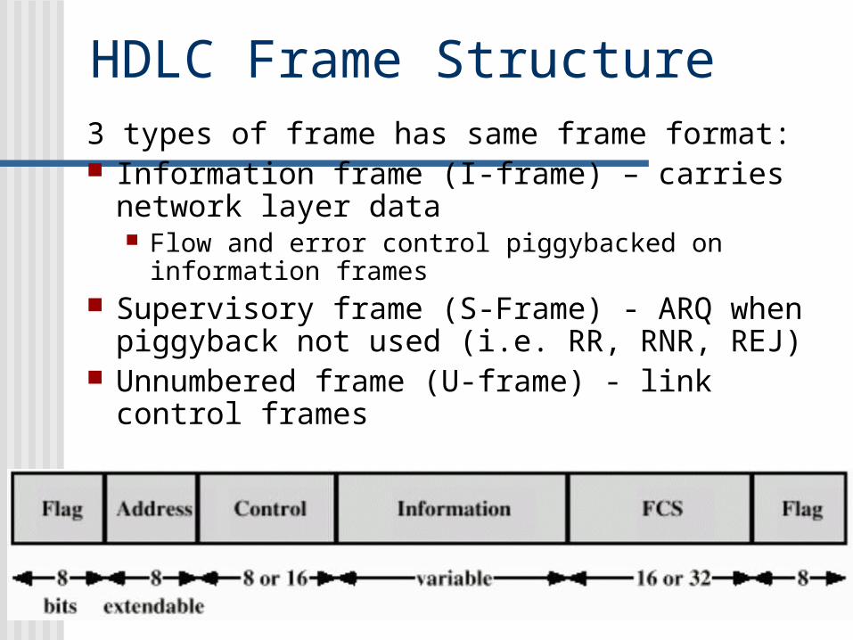
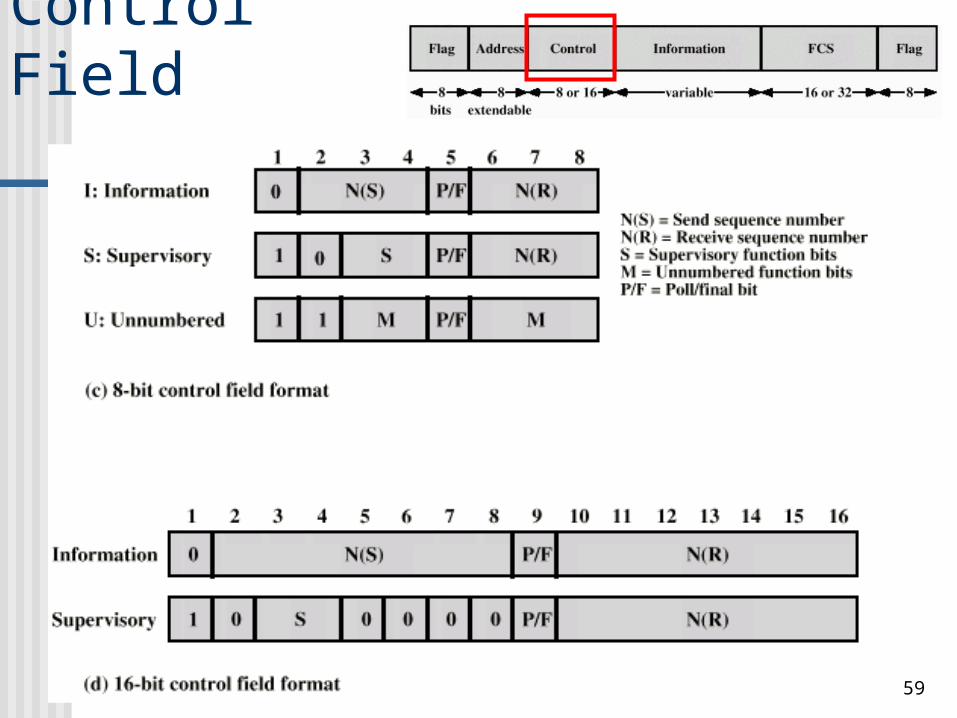
HDLC Frame Structure3 types of frame has same frame format: Information frame (I-frame) – carries
network layer data Flow and error control piggybacked on
information frames Supervisory frame (S-Frame) - ARQ when
piggyback not used (i.e. RR, RNR, REJ) Unnumbered frame (U-frame) - link control
frames
56
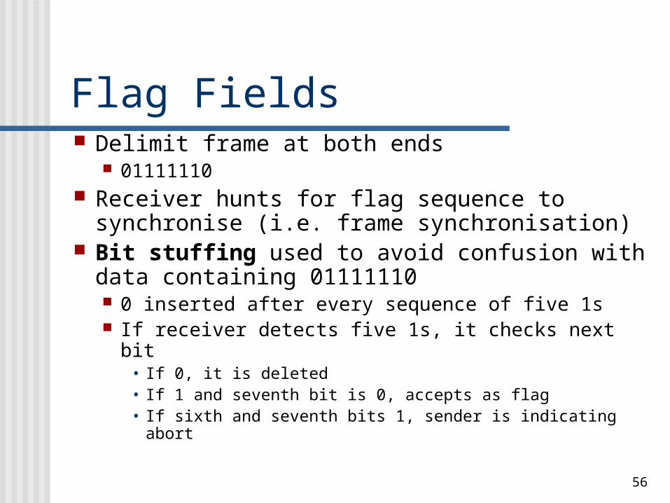
Flag Fields Delimit frame at both ends
01111110 Receiver hunts for flag sequence to
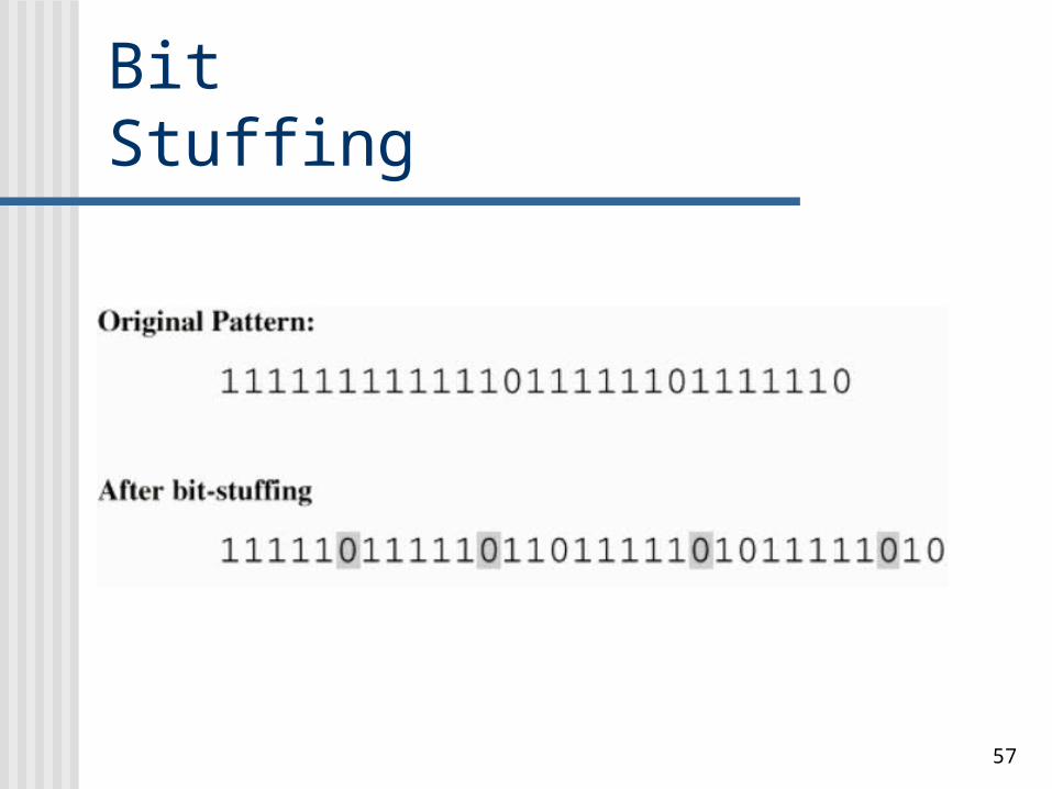
synchronise (i.e. frame synchronisation) Bit stuffing used to avoid confusion with
data containing 01111110 0 inserted after every sequence of five 1s If receiver detects five 1s, it checks next bit
• If 0, it is deleted• If 1 and seventh bit is 0, accepts as flag• If sixth and seventh bits 1, sender is indicating abort
57
Bit Stuffing
58
Control Field Different for different frame type First one or two bits of control field
identify frame type
59
Control Field
60
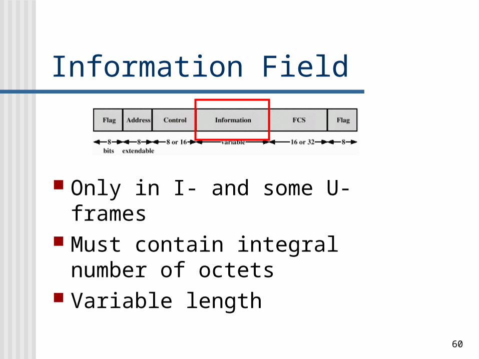
Information Field
Only in I- and some U-frames Must contain integral number of
octets Variable length
61
Frame Check Sequence (FCS) Field Error detection code (i.e. redundant
bits) 16-bit CRC
Optional 32-bit CRC
62
HDLC Operation Three phases
Initialization (Connection setup)
Data transfer Disconnect
(Connection Termination)
63
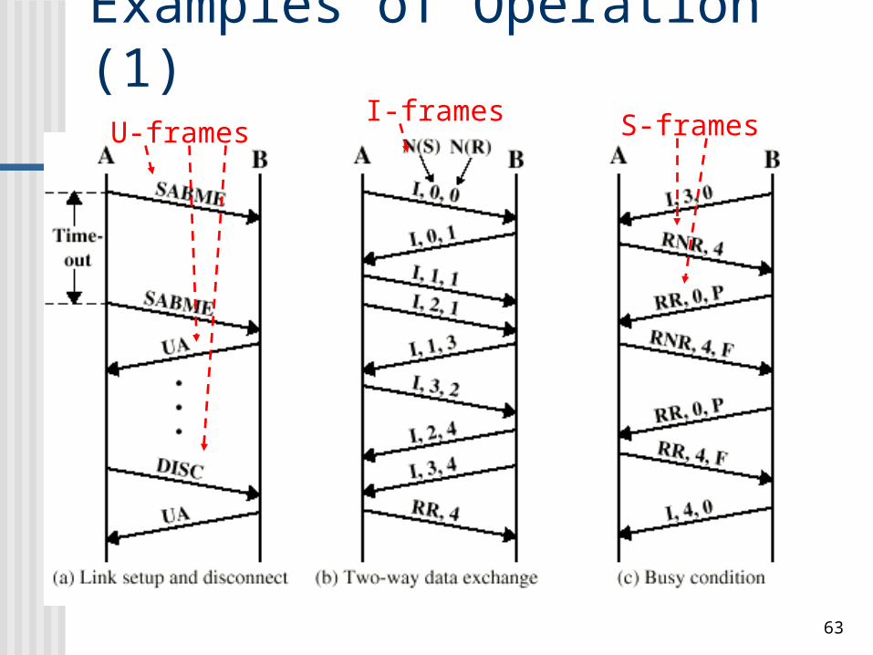
Examples of Operation (1)U-frames
I-frames S-frames
64
Examples of Operation (2)
65
Summary Flow control and error
control through the same scheme
HDLC a basis for many other data link layer protocols
Read Stallings sec. 6.2, 6.3, 6.5 and chap 7
Next: LAN Overview