Embed Size (px)
Citation preview

1
1
Definitions: Methods of Calculations
The following terms and definitions correspond largely to those defined in IEC60909-0. Refer to this standard for all the terms not used in this book.
The terms short circuit and ground fault describe faults in the isolation of oper-ational equipment, which occur when live parts are shunted out as a result.
1) Causes:• Overtemperatures due to excessively high overcurrents;• Disruptive discharges due to overvoltages; and• Arcing due to moisture together with impure air, especially on insulators.
2) Effects:• Interruption of power supply;• Destruction of system components; and• Development of unacceptable mechanical and thermal stresses in electri-
cal operational equipment.3) Short circuit: According to IEC 60909-0, a short circuit is the accidental or
intentional conductive connection through a relatively low resistance orimpedance between two or more points of a circuit that are normally atdifferent potentials.
4) Short-circuit current: According to IEC 60909-0, a short-circuit currentresults from a short circuit in an electrical network.It is necessary to differentiate between the short-circuit current at the posi-tion of the short circuit and the transferred short-circuit currents in the net-work branches.
5) Initial symmetrical short-circuit current: The effective value of the symmet-rical short-circuit current at the moment at which the short circuit arises,when the short-circuit impedance has its value from the time zero.
6) Initial symmetrical short-circuit apparent power: The short-circuit powerrepresents a fictitious parameter. During the planning of networks, theshort-circuit power is a suitable characteristic number.
Short Circuits in Power Systems: A Practical Guide to IEC 60909-0, Second Edition. Ismail Kasikci.© 2018 Wiley-VCH Verlag GmbH & Co. KGaA. Published 2018 by Wiley-VCH Verlag GmbH & Co. KGaA.

2 1 Definitions: Methods of Calculations
7) Peak short-circuit current: The largest possible momentary value of the shortcircuit occurring.
8) Steady-state short-circuit current: Effective value of the initial symmetricalshort-circuit current remaining after the decay of all transient phenomena.
9) Direct current (d.c.) aperiodic component: Average value of the upper andlower envelope curve of the short-circuit current, which slowly decaysto zero.
10) Symmetrical breaking current: The effective value of the short-circuit cur-rent that flows through the contact switch at the time of the first contactseparation.
11) Equivalent voltage source: The voltage at the position of the short circuit,which is transferred to the positive-sequence system as the only effectivevoltage and is used for the calculation of the short-circuit currents.
12) Superposition method: Considers the previous load of the network before theoccurrence of the short circuit. It is necessary to know the load flow and thesetting of the transformer step switch.
13) Voltage factor: Ratio between the equivalent voltage source and the networkvoltage, Un, divided by
√3.
14) Equivalent electrical circuit: Model for the description of the network by anequivalent circuit.
15) Far-from-generator short circuit: The value of the symmetrical alternatingcurrent (a.c.) periodic component remains essentially constant.
16) Near-to-generator short circuit: The value of the symmetrical a.c. periodiccomponent does not remain constant. The synchronous machine first deliv-ers an initial symmetrical short-circuit current, which is more than twice therated current of the synchronous machine.
17) Positive-sequence short-circuit impedance: The impedance of the positive-sequence system as seen from the position of the short circuit.
18) Negative-sequence short-circuit impedance: The impedance of the negative-sequence system as seen from the position of the short circuit.
19) Zero-sequence short-circuit impedance: The impedance of the zero-sequencesystem as seen from the position of the short circuit. Three times the valueof the neutral point to ground impedance occurs.
20) Short-circuit impedance: Impedance required for the calculation of theshort-circuit currents at the position of the short circuit.
1.1 Time Behavior of the Short-Circuit Current
Figure 1.1 shows the time behavior of the short-circuit current for the occurrenceof far-from-generator and near-to-generator short circuits.
The d.c. aperiodic component depends on the point in time at which the shortcircuit occurs. For a near-to-generator short circuit, the subtransient and thetransient behaviors of the synchronous machines are important. Following thedecay of all transient phenomena, the steady state sets in.

1.2 Short-Circuit Path in the Positive-Sequence System 3
Current
Current
(a)
(b)
Top envelope
Top envelope
Bottom envelope
Bottom envelope
Time
Time
d.c. component id.c.of the short-circuit current
d.c. component id.c.of the short-circuit current
A
i p
A
i p
2√2I″ k
2√2I″ k
2√2I
k
2√2I
k=2√
2I″ k
Figure 1.1 Time behavior of the short-circuit current (see Ref. [1]). (a) Far-from-generator shortcircuit and (b) near-to-generator short circuit. I′′k : initial symmetrical short-circuit current; ip:peak short-circuit current; id.c.: decaying d.c. aperiodic component; and A: initial value of d.c.aperiodic component.
1.2 Short-Circuit Path in the Positive-Sequence System
For the same external conductor voltages, a three-phase short circuit allowsthree currents of the same magnitude to develop among the three conductors.Therefore, it is only necessary to consider one conductor in further calculations.Depending on the distance from the position of the short circuit from thegenerator, it is necessary to consider near-to-generator and far-from-generatorshort circuits separately. For far-from-generator and near-to-generator shortcircuits, the short-circuit path can be represented by a mesh diagram with ana.c. voltage source, reactances X, and resistances R (Figure 1.2). Here, X and Rreplace all components such as cables, conductors, transformers, generators,and motors.

4 1 Definitions: Methods of Calculations
X
Rk
R
Xk ib
ik
~ u(t) = u sin ωtˆ
Figure 1.2 Equivalent circuit of theshort-circuit current path in thepositive-sequence system.
The following differential equation can be used to describe the short-circuitprocess:
ik ⋅ Rk + Lkdik
dt= u ⋅ sin(𝜔t + 𝜓) (1.1)
where 𝜓 is the phase angle at the point in time of the short circuit. The inho-mogeneous first-order differential equation can be solved by determining thehomogeneous solution ik and a particular solution I′′k .
ik = i′′k∼ + ik− (1.2)
The homogeneous solution, with the time constant 𝜏g = L/R, yields thefollowing:
ik = −u√(R2 + X2)
et∕𝜏g sin(𝜓 − 𝜑k) (1.3)
For the particular solution, we obtain the following:
i′′k = −u√(R2 + X2)
sin(𝜔t + 𝜓 − 𝜑k) (1.4)
The total short-circuit current is composed of both the components:
ik = −u√(R2 + X2)
[sin(𝜔t + 𝜓 − 𝜑k) − et∕𝜏g sin(𝜓 − 𝜑k)] (1.5)
The phase angle of the short-circuit current (short-circuit angle) is then, inaccordance with the above equation,
𝜑k = 𝜓 − 𝜈 = arctan XR
(1.6)
Figure 1.3 shows the switching processes of the short circuit.For the far-from-generator short circuit, the short-circuit current is, therefore,
made up of a constant a.c. periodic component and the decaying d.c. aperiodiccomponent. From the simplified calculations, we can now reach the followingconclusions:
1) The short-circuit current always has a decaying d.c. aperiodic component inaddition to the stationary a.c. periodic component.
2) The magnitude of the short-circuit current depends on the operating angle ofthe current. It reaches a maximum at 𝛾 = 90∘ (purely inductive load). This caseserves as the basis for further calculations.
3) The short-circuit current is always inductive.

1.3 Classification of Short-Circuit Types 5
id.c.
0 90 180 270 360 450 540 630 720
ik
ikd
2 I″kκ
2 I″k
Figure 1.3 Switching processes of the short circuit.
1.3 Classification of Short-Circuit Types
For a three-phase short circuit, three voltages at the position of the short circuitare zero. The conductors are loaded symmetrically. Therefore, it is sufficientto calculate only in the positive-sequence system. The two-phase short-circuitcurrent is less than that of the three-phase short circuit, but largely close tosynchronous machines. The single-phase short-circuit current occurs mostfrequently in low-voltage (LV) networks with solid grounding. The doubleground connection occurs in networks with a free neutral point or with a groundfault neutralizer grounded system.
For the calculation of short-circuit currents, it is necessary to differentiatebetween the far-from-generator and the near-to-generator cases.1) Far-from-generator short circuit
When double the rated current is not exceeded in any machine, we speak of afar-from-generator short circuit.
I′′k < 2 ⋅ IrG (1.7)or when
I′′k = Ia = Ik (1.8)
2) Near-to-generator short circuitWhen the value of the initial symmetrical short-circuit current I′′k exceedsdouble the rated current in at least one synchronous or asynchronous machineat the time the short circuit occurs, we speak of a near-to-generator shortcircuit.
I′′k 2 > IrG (1.9)

6 1 Definitions: Methods of Calculations
or when
I′′k > Ia > Ik (1.10)
Figure 1.4 schematically illustrates the most important types of short circuitsin three-phase networks.
1) Three-phase short circuits:• connection of all conductors with or without simultaneous contact to
ground;• symmetrical loading of the three external conductors;• calculation only according to single phase.
2) Two-phase short circuits:• unsymmetrical loading;• all voltages are nonzero;• coupling between external conductors;• for a near-to-generator short circuit I′′k2 > I′′k3
3) Single-phase short circuits between phase and PE:• very frequent occurrence in LV networks.
4) Single-phase short circuits between phase and N:• very frequent occurrence in LV networks.
5) Two-phase short circuits with ground:• in networks with an insulated neutral point or with a suppression coil
grounded system I′′kEE < I′′k2E.
L3
L2
L1
(a) (b)
(c) (d)
L3
L2
L1
Short-circuit current Partial short-circuit currentsin conductors and earth return
L3
L2
L1
L3
L2
L1
I″k3 I″k2
I″k1I″kE2E
I″k2EL2I″k2EL3
Figure 1.4 Types of short-circuit currents in three-phase networks [1].

1.4 Methods of Short-Circuit Calculation 7
With a suppression coil grounded system, a residual ground fault current IRestoccurs. IC and IRest are special cases of I′′k .
1.4 Methods of Short-Circuit Calculation
The measurement or calculation of short-circuit current in LV networks on finalcircuits is very simple. In meshed and extensive power plants, the calculation ismore difficult because of the short-circuit current of several partial short-circuitcurrents in conductors and earth return.
The short-circuit currents in three-phase systems can be determined by threedifferent calculation procedures:
1) superposition method for a defined load flow case;2) calculating with the equivalent voltage source c⋅Un√
3at the fault location; and
3) transient calculation.
1.4.1 Superposition Method
The superposition method is an exact method for the calculation of the short-circuit currents. The method consists of three steps. The voltage ratios andthe loading condition of the network must be known before the occurrence ofthe short circuit. In the first step, the currents, voltages, and internal voltagesfor steady-state operation before onset of the short circuit are calculated(Figure 1.5b). The calculation considers the impedances, power supply feeders,and node loads of the active elements. In the second step, the voltage applied tothe fault location before the occurrence of the short circuit and the current dis-tribution at the fault location are determined with a negative sign (Figure 1.5b).This is the only voltage source in the network. The internal voltages are short-circuited. In the third step, both the conditions are superimposed. We thenobtain a zero voltage at the fault location. The superposition of the currents alsoleads to the value zero. The disadvantage of this method is that the steady-statecondition must be specified. The data for the network (effective and reactivepower, node voltages, and the step settings of the transformers) are oftendifficult to determine. The question also arises: Which operating state leads tothe greatest short-circuit current?
The superposition method assumes that the power flow is known of the net-work before the fault inception and the setting of the tap changer of the trans-former and the voltage set points of the generators.
By the superposition method, the power state is superimposed with an amend-ments state before the short circuit occurs. For this condition, the considerationof positive sequence is sufficient.
The network consists of i= 1,…,n load nodes and j= 1,…,m generators andpower supply applications. With a suitable program, the load flow can be cal-culated for a network condition. After the changes in the network through theshort circuit, there are other values at each node. For a three-phase short circuit,the voltage at the fault point equals zero. This condition is also fulfilled when the

1
F
n
G 3~
Pos
itive
-seq
uenc
e
1
F
n
~
. . . . . .
. . .
. . . . .
. . . . .
(d)
(a)
~
1
F
n~
~
~+
. . . . . .
. . .
(b)
1
F
n~
~
~+
. . . . . .
. . .
(c)
XQ
XQ
XQ
U(1
)Q
U(1
)Q
U(1
)f
U(1
)f
–U
(1)f
–U
(1)f
X″ d
X″ d
X″ d
E″
E″
+
1 m
Fig
ure
1.5
Met
hods
fort
hesh
ort-
circ
uitc
alcu
latio
n.(a
)Sin
gle
line
diag
ram
;(b
)vol
tage
sour
ceat
the
faul
tloc
atio
n;(c
)sup
erp
ositi
on;a
nd(d
)equ
ival
ent
volt
age
sour
ce.

1.4 Methods of Short-Circuit Calculation 9
same voltage is given at the fault location but with an opposite voltage sign. Allnetwork feeders, synchronous, and asynchronous machines are replaced by theirinternal impedances (Figure 1.5d).
The calculation of a short-circuit current is a linear problem that can be solvedeasily with linear equations. There is a linear relationship between the node volt-ages and node currents.
With the help of nodal admittance matrix systems, linear equations can besolved. All impedances are converted to the LV side of the transformers. In con-trast to the load flow calculation, an iteration is not required. The equations areobtained at the short-circuit location i in matrix notation.
i = Y ⋅ u (1.11)
⎡⎢⎢⎢⎢⎢⎢⎢⎢⎣
00⋮
I′′ki
⋮
0
⎤⎥⎥⎥⎥⎥⎥⎥⎥⎦
=
⎡⎢⎢⎢⎢⎢⎢⎢⎢⎣
Y 11 Y 1n
Y 21 Y 2n
⋮ ⋮
Y i1 Y in
⋮ ⋮
Y n1 Y nn
⎤⎥⎥⎥⎥⎥⎥⎥⎥⎦
⋅
⎡⎢⎢⎢⎢⎢⎢⎢⎢⎢⎣
U1
U2
⋮
−c Un√3
⋮
Un
⎤⎥⎥⎥⎥⎥⎥⎥⎥⎥⎦
(1.12)
After inversion, we obtain the following:
u = Y−1 ⋅ i (1.13)
⎡⎢⎢⎢⎢⎢⎢⎢⎢⎢⎣
U1
U2
⋮
−c Un√3
⋮
Un
⎤⎥⎥⎥⎥⎥⎥⎥⎥⎥⎦
=
⎡⎢⎢⎢⎢⎢⎢⎢⎢⎣
Z11 Z1n
Z21 Z2n
⋮ ⋮
Zi1 Zin
⋮ ⋮
Zn1 Znn
⎤⎥⎥⎥⎥⎥⎥⎥⎥⎦
⋅
⎡⎢⎢⎢⎢⎢⎢⎢⎢⎣
00⋮
I′′ki
⋮
0n
⎤⎥⎥⎥⎥⎥⎥⎥⎥⎦
(1.14)
From the ith row of the equation results
−cUn√
3= Zii ⋅ I′′ki (1.15)
The initial short-circuit a.c. can be calculated by redirecting the above equation:
I′′ki = −c ⋅ Un√3 ⋅ Zii
(1.16)
For the node voltages, follow:
Uk = Zki ⋅ I′′ki (1.16a)
10 1 Definitions: Methods of Calculations
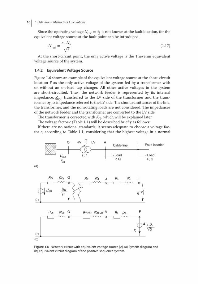
Since the operating voltage U(1)f = Un√3
is not known at the fault location, for theequivalent voltage source at the fault point can be introduced.
−U (1)f =c ⋅ Un√
3(1.17)
At the short-circuit point, the only active voltage is the Thevenin equivalentvoltage source of the system.
1.4.2 Equivalent Voltage Source
Figure 1.6 shows an example of the equivalent voltage source at the short-circuitlocation F as the only active voltage of the system fed by a transformer withor without an on-load tap changer. All other active voltages in the systemare short-circuited. Thus, the network feeder is represented by its internalimpedance, ZQt, transferred to the LV side of the transformer and the trans-former by its impedance referred to the LV side. The shunt admittances of the line,the transformer, and the nonrotating loads are not considered. The impedancesof the network feeder and the transformer are converted to the LV side.
The transformer is corrected with KT, which will be explained later.The voltage factor c (Table 1.1) will be described briefly as follows:If there are no national standards, it seems adequate to choose a voltage fac-
tor c, according to Table 1.1, considering that the highest voltage in a normal
jXQ jXT jXL
HV LVT
t : 1
01
(a)
Cable line
Q
UQ
LoadP, Q
LoadP, Q
RQ
jXQt jXTLVK jXLQRQt RTLVK RL
RT RLA F
Q FAFault location
01
(b)
A F
UnQ
UqQ3
c.Un
3
I″kQ
I″k
I″k
Figure 1.6 Network circuit with equivalent voltage source [2]. (a) System diagram and(b) equivalent circuit diagram of the positive-sequence system.

1.4 Methods of Short-Circuit Calculation 11
Table 1.1 Voltage factor c, according to IEC 60909-0: 2016-10 [1].
Nominal voltage, Un Voltage factor c for calculation of
Maximum short-circuitcurrents (cmax)a)
Minimum short-circuitcurrents (cmin)
Low voltage
100–1000 V
(IEC 38, Table I)
1.05b)
1.10c)
0.95b)
0.9c)
High voltaged)
>1–35 kV
(IEC 38, Tables III and IV)
1.10 1.00
a) cmax Un should not exceed the highest voltage Um for equipment of power systems.b) For LV systems with a tolerance of ±6%, for example, systems renamed from 380 to
400 V.c) For LV systems with a tolerance of ±10%.d) If no nominal voltage is defined, cmax Un =Um or cmin Un = 0.90 Um should be applied.
(undisturbed) system does not differ, on average, by more than approximately+5% (some LV systems) or+10% (some high-voltage, HV, systems) from the nom-inal system voltage Un [3].
1) The different voltage values depending on time and position2) The step changes of the transformer switch3) The loads and capacitances in the calculation of the equivalent voltage source
can be neglected4) The subtransient behavior of generators and motors must be considered.
This method assumes the following conditions:
1) The passive loads and conductor capacitances can be neglected2) The step setting of the transformers need not be considered3) The excitation of the generators need not be considered4) The time and position dependence of the previous load (loading state) of the
network need not be considered.
1.4.3 Transient Calculation
With the transient method, the individual operating equipment and, as a result,the entire network are represented by a system of differential equations. Thecalculation is very tedious. The method with the equivalent voltage source is asimplification relative to the other methods. Since 1988, it has been standard-ized internationally in IEC 60909-0. The calculation is independent of a currentoperational state. Therefore, in this book, the method with the equivalent voltagesource will be dealt with and discussed.

12 1 Definitions: Methods of Calculations
1.4.4 Calculating with Reference Variables
There are several methods for performing short-circuit calculations with abso-lute and reference impedance values. A few methods are summarized here, andexamples are calculated for comparison. To define the relative values, there aretwo possible reference variables.
For the characterization of electrotechnical relationships, we require the fourparameters:1) voltage U in V;2) current I in A;3) impedance Z in Ω; and4) apparent power S in VA.
Three methods can be used to calculate the short-circuit current:1) The Ohm system: units – kV, kA, V, and MVA.2) The per-unit (pu) system: this method is used predominantly for electrical
machines; all four parameters u, i, z, and s are given as per unit (unit= 1). Thereference value is 100 MVA. The two reference variables for this system areUB and SB. Example: The reactances of a synchronous machine Xd, X′
d, andX′′
d are given in pu or in %pu, multiplied by 100%.3) The %/MVA system: this system is especially well suited for the quick deter-
mination of short-circuit impedances. As a formal unit, only the % symbol isadded.
1.4.4.1 The Per-Unit AnalysisToday, the power system consists of complex and complicated mesh, ring, andradial networks with many transformers, generators, and cables. The calcula-tion of such a circuit can be very tedious and incorrect. The use of sophisticatedcomputer programs is a big help for engineers. On the other hand, for a quickcalculation a simple method, per unit system also can be used. However, thismethod is not accepted worldwide and is not standardized by IEC, EN, or IEEEcommittees.
The pu method uses the electrical variables U, I,Z, and S. They are based on adimensionless same references, namely, Ubase, Ibase, Zbase, or Sbase. The resultingdimensionless quantities are described with the lowercase u, i, z, or s.
A pu system is defined as follows:
Per unit value (pu) =the actual value (in any unit)
the base or reference value (in the same unit)
upu =U
Ubase
A reference voltage and a reference apparent power are selected and then ref-erence current and impedance are calculated as follows:
Zbase =U2
base
Sbase
Ibase =Sbase
Ubase

1.4 Methods of Short-Circuit Calculation 13
Only a single global base value is selected in the short-circuit currentcalculation. This reference value is then used for all other networks. The choiceof reference values can be carried out arbitrarily in principle. However, it isappropriate to select the rated voltage at the short-circuit location as a referencevoltage. For example, as reference apparent power is the rated apparent powerof the largest transformer in the network or a power of the same selectedmagnitude (e.g., 100 MVA). The best choice of base can be achieved when theimpedances and currents in easily handled orders of magnitude.
It should be noted that related parameters’ individual resources, such as the rel-ative short-circuit voltage of a transformer ukr or related subtransient reactancex′′
d of the generator, are always relative to a base, which consists of the designparameters of the particular equipment. In a short-circuit current calculation asper pu method, these parameters must first be converted to the selected globalbasis. If we give an example for voltage and current, the expression is as follows:
Upu =Uactual
Ubase
Ipu =Iactual
Ibase
Note that the voltage according to the international system of units (SI) is notV , but U . The letter V is a unit in this case. V is used especially in Anglo-Saxoncountries.
For other values, we can write for 1 pu impedance (Ω):
Zbase =Ubase
Ibase=
Ubase
Ibaseor in pu Zpu =
Upu
Ipu
Ibase =Sbase
Ubase
We convert the values to pu:
Rpu = RZbase
Xpu = XZbase
Remember that a symmetrical three-phase system has two voltages, line–linevoltage UL (Un) and ULN (U0). By definition:
ULN =UL√
3Now consider:
ULNpu =ULN
ULNbase
It follows that:
ULNpu =ULN
ULNbase=
UL∕√
3
ULbase∕√
3=
UL
ULbase= ULpu
Consider that the factor√
3 disappears in the pu equation.

14 1 Definitions: Methods of Calculations
1.4.4.2 The %/MVA MethodThe %/MVA method can be considered as a modification of the pu method anddesigned specifically for the HV network calculation. The impedances of theelectrical equipment can be determined easily in %/MVA from the synchronousmachine and transformer characteristics. It utilizes the fact that for the pucalculation, apparent power Sbase is completely arbitrary. Consequently, insteadof Sbase, the dimensionless value 1 is inserted. This has the result that the relatedsizes of the pu are no longer dimensionless.
The related impedances can be represented in %/MVA. The %/MVA methodhas the advantage that a conversion with t2 or 1/t2 eliminates the transforma-tion of impedances in the voltage level on the transformers. Furthermore, allimpedances of resources and the dimensioning data can be obtained from thenameplate.
z = ZU2
base
× 100%
u = ZUbase
× 100%
i = I ⋅ Ubase
1.4.5 Examples
1.4.5.1 Characteristics of the Short-Circuit CurrentThe short-circuit current is composed of two parts. The first term describes thea.c. (continuous current) and the second term the compensation process.
ik(t) = ik ⋅ sin(𝜔t − Ψ + 𝜑u) − ik ⋅ sin(Ψ − 𝜑) ⋅ e−(t∕𝜏)
The size of the short-circuit current is therefore dependent on the phase angle𝜑 = arc tan X
R, the time constant 𝜏 = L
R, the time t, and the switching angle Ψ.
Thus we can obtain many shifts by changing the sizes (Figure 1.7).Example: RQ∕XQ = 0.176, 𝜑 = −0∘, 𝜑u = −90∘, 𝜏 = ∞ms, 3 ⋅ 𝜏 = ∞ms,
𝜅 = 1.02.For further considerations, one can write
sin(𝜔t − 𝜑) = 1, RX
= 1tan 𝜑
, Ψ = 0
1.4.5.2 Calculation of Switching ProcessesGiven are the following sizes of short-circuit current (Figure 1.8):
RQ
XQ= 0.176, 𝜑 = −80∘, 𝜑u = −170∘, 𝜏 = 0.018 ms,
3 ⋅ 𝜏 = 0.054 ms, 𝜅 = 1.597
Draw the switching process of the short circuit.
1.4.5.3 Calculation with pu SystemGiven is a system with 20/6 kV network (Figure 1.9).

1.4 Methods of Short-Circuit Calculation 15
–90 0 90 180 270 360 450 540 630 720
ik
id.c.
ikd
–1
0
1
2
Figure 1.7 Short-circuit current components – switch on.
–180 –90 0 90 180 270 370
0
t = 0
1
1
Short circuit
A
–A
φu
φ
ik
id.c.
ia.c.
Figure 1.8 Switching process.
Transformer:
SrT = 25 MVA, ukrT = 13%, 20∕6.3 kV
Motors 1 and 2:
2 × PrM = 2.3 MW, UrM = 6 kV, cos𝜑rM = 0.86p = 2, Ia∕IrM = 5, 𝜂 = 0.97

16 1 Definitions: Methods of Calculations
Network 2000 MVA
20 kV
6 kV
T
Q
Motor 3 + 4
M3~
M3~
Motor 1 + 2
Figure 1.9 Impact of engineson the current.
Motors 3 and 4:
2 × PrM = 0.36 MW, UrM = 6 kV, cos 𝜑rM = 0.87p = 1, Ia∕IrM = 5.5, 𝜂 = 0.98
1.4.5.4 Calculation with pu MagnitudesGiven: UB = Un = 6 kV bzw. 20 kV, SB = 100 MVA. Calculate example 1.4.5.3using pu magnitude.
U∗ =UUB
I∗ =I ⋅ UB
SBZ∗ =
Z ⋅ SB
U2B
S∗ =SSB
Transformer translation in pu system:
t∗r =UrTOS
UrTUS⋅
UB,6 kV
UB,20 kV= 20 kV
6.3 kV⋅
6 kV20 kV
= 0.9524
Power supply:
Z∗Qt =
c ⋅ U2∗nQ
S′′∗kQ
⋅1
t2∗r
=1.1 ⋅ (1 ⋅ pu)2
10 pu⋅
10.95242 = 0.1212 pu
Transformer:
Z∗T =
ukrT
100%⋅
U2rTUS
SrT⋅
SB
U2B,6 kV
= 13%100%
⋅(6.3 kV)2
25 MVA⋅
100 MVA(6 kV)2 = 0.5733 pu
Impedance:
Z∗k = Z∗
Qt + Z∗T = 0.6945 pu
I′′∗k without motors.
I′′∗k =c ⋅ U∗
n√3 ⋅ Z∗
k
=1.1 ⋅ 1 pu√
3 ⋅ 0.6945 pu= 0.9144 pu
Current in kA:
I′′k = I∗k ⋅SB
UB,6 kV= 0.9144 pu ⋅
100 MVA6 kV
= 15.24 kA

1.4 Methods of Short-Circuit Calculation 17
Impedances of motors in pu systems:
Z∗m1 = 1
2𝜂 ⋅ cos𝜑Ian∕IrM
⋅U2
rM
PrM⋅
SB
U2B,6 kV
= 12𝜂 ⋅ cos 𝜑Ian∕IrM
⋅SB
PrM
= 12⋅
0.86 ⋅ 0.975
⋅100 MVA2.3 MVA
= 3.63 pu
Zm2 = 12⋅
0.87 ⋅ 0.985.5
⋅100 MVA0.36 MVA
= 21.5 pu
Partly current:
I′′∗km1 =c ⋅ U∗
n√3 ⋅ Z∗
m1
=1.1 ⋅ 1 pu√3 ⋅ 3.63 pu
= 0.175 pu
I′′km1 = 2.92 kA
I′′∗km2 = 0.0295 pu
I′′km2 = 0.492 kA
1.4.5.5 Calculation with pu System for an Industrial SystemGiven is Figure 1.10. Calculate the short circuit power and short-circuit currentsof an industrial power plant with the pu method.
First, the equivalent circuit diagram is drawn (Figure 1.11).
154.5 kV
Q
31.5 kV
1600 kVA6%
50 MVA11.94%
3 × 477 MCM
l2 = 4.1 km
4×(1 × 240) XLPE
l3 = 0.045 km
4×(1 × 240) XLPE
l1 = 0.165 km
T1
T2Cable Overhead line Cable
50 MVA11.94%
0.4 kV
31.5 kV
l″k1 = 5.73 kAl″k3 = 7.75 kA
Figure 1.10 Supply for an industrial company.
~cUn
3
XQ
XT1
XL1 XL2 XL3 XT3
XT2
I″k3
Figure 1.11 Equivalent circuit diagram in positive sequence.

18 1 Definitions: Methods of Calculations
Impedance of the power supply:
ZQ =Un√3 ⋅ I′′k3
= 154 kV√3 ⋅ 7.75 kA
= 11.486Ω
Short-circuit power of the supply:
S′′kQ =
√3 ⋅ Un ⋅ I′′k3 =
√3 ⋅ 154 kV ⋅ 7.75 kA = 2064.75 MVA
Reactance of the feed:
XQ = 1 ⋅ 100S′′
kQ= 1 ⋅ 100
2064.75 MVA= 0.0484 pu
Reactance of transformers:
XT =XT1 ⋅ XT2
XT1 + XT2= 5.97%
XT = 10050 MVA + 50 MVA
⋅ 5.97% = 0.0597 pu
Total reactance:
XG = XQ + XT = 0.0484 pu + 0.0597 pu = 0.10813 pu
Ipu = UXG
= 10.10813 pu
= 9.248 pu
Short-circuit power:
XkQ = 1 pu ⋅ 100 = 9.248 ⋅ 100 = 924.8 MVA
XHpu =XH
XB=
XFLXB
XB = U2
100= 31.5 kV2
100= 9.922Ω
XH = XH1 + XH1
XT = 0.0161 + 1.5088 = 1.528 puXH1 = l1 ⋅ XH1 = 0.21 km ⋅ 0.0754Ω∕km = 0.0161ΩXH2 = l2 ⋅ XH2 = 4.1 km ⋅ 0.368Ω∕km = 1.5088Ω
XHpu = 1.5269.922
= 0.154 pu
XG2 = XG1 + XH = 0.10813 + 0.154 = 0.26213 pu
IB = S√3 ⋅ U
= 100 ⋅ 103√
3 ⋅ 31.5 kV= 1835 A
Ipu = 1XG2
= 10.26213 pu
= 3.8 pu
On distribution transformer:
I′′k = Ipu ⋅ IB = 3.8 pu ⋅ 1835 A = 6.973 kA

1.4 Methods of Short-Circuit Calculation 19
Short-circuit power on the primary side of the transformer:
S′′k =
√3 ⋅ U ⋅ I′′k =
√3 ⋅ 31.5 kV ⋅ 6.973 kA = 380 MVA
Short-circuit power on the secondary side of the transformer:
XTR = 1001.6
⋅ 0.06 = 3.75 pu
XG3 = XG2 + XG1 = 0.26213 + 3.75 = 4.10213 pu
Ipu = 1XG3
= 14.10213 pu
= 0.24924 pu
I′′k(0.4 kV) = Ipu ⋅ IB = 0.24924 pu ⋅ 1.835 kA = 0.457 kA
1.4.5.6 Calculation with MVA SystemFigure 1.12 shows a power plant with auxiliary power system and power sup-ply. Calculate using the %/MVA system at the busbar SS circuit power, the peakshort-circuit current and the breaking current.
The total reactance at the fault is calculated with the aid of the equivalent circuitshown in Figure 1.13 by gradual power conversion.
1) Calculation of the reactance of the individual resourcesNetwork reactance:
XQ = 1.1 ⋅ 100S′′
kQ= 1.1 ⋅ 100
8000 MVA= 0.0138%∕MVA
Transformer 1:
XT1 =ukr
SrT1= 13
100 MVA= 0.1300%∕MVA
Generator:
XG =x′′
d
SrG= 11.5
93.7 MVA= 0.1227%∕MVA
M3~
93.7 MVA11.5%
8 MVA7%
100 MVA13%
220 kV
SS8 x 0.46 MVAIA = 5 IrM
G3~
M3~
2.69 MVAIA = 5 IrM
Q
8000 MVA 6 kV
Figure 1.12 Power plant with auxiliary power system.

20 1 Definitions: Methods of Calculations
~
0.72
41
0.12
27
0.87500.
0138
~5.
4348
Fault location
0.13
00
7.43
9
0.8750
0.14
38
0.12
27
3.13
97
~
Fault location
0.8750
0.06
62
~
Fault location
3.13
97
0.94
12
~
Fault location
3.13
97
cUn
3
cUn
3
I″k3 I″k3
cUn
3
cUn
3
cUn
3
I″k3 I″k3
I″k3
Figure 1.13 Equivalent circuit diagram in positive sequence.
Transformer 2:
XT2 =ukr
SrT2= 7
8 MVA= 0.8750%∕MVA
Asynchronous motor:
XM1 =IrM∕IA
SrM⋅ 100 = 1
5 ⋅ 2.69 MVA⋅ 100 = 7.439%∕MVA
Asynchronous motor group:
XM2 =IrM∕IA
SrM⋅ 100 = 1
5 ⋅ 8 ⋅ 0.46 MVA⋅ 100 = 5.4348%∕MVA
Total reactance at the fault point:
S′′k = 1.1 ⋅ 100%
Xk= 1.1 ⋅ 100%
0.7225%∕MVA= 152 MVA
2) Parts of each feed on the short-circuit power.With the total reactance, we can determine the circuit power.
S′′k = 1.1 ⋅ 100%
XG= 1.1 ⋅ 100%
0.7241= 152 MVA
Thus, the proportions of the individual feeds to the short-circuit power:
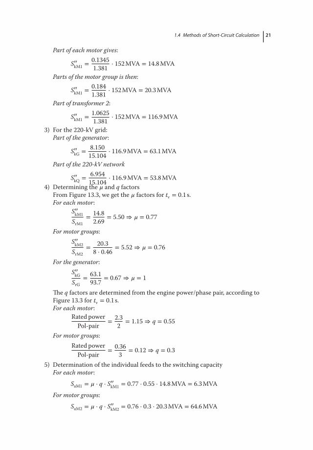
1.4 Methods of Short-Circuit Calculation 21
Part of each motor gives:
S′′kM1 = 0.1345
1.381⋅ 152 MVA = 14.8 MVA
Parts of the motor group is then:
S′′kM1 = 0.184
1.381⋅ 152 MVA = 20.3 MVA
Part of transformer 2:
S′′kM1 = 1.0625
1.381⋅ 152 MVA = 116.9 MVA
3) For the 220-kV grid:Part of the generator:
S′′kG = 8.150
15.104⋅ 116.9 MVA = 63.1 MVA
Part of the 220-kV network
S′′kQ = 6.954
15.104⋅ 116.9 MVA = 53.8 MVA
4) Determining the 𝜇 and q factorsFrom Figure 13.3, we get the 𝜇 factors for tv = 0.1 s.For each motor:
S′′kM1
SrM1= 14.8
2.69= 5.50 ⇒ 𝜇 = 0.77
For motor groups:S′′
kM2
SrM2= 20.3
8 ⋅ 0.46= 5.52 ⇒ 𝜇 = 0.76
For the generator:S′′
kG
SrG= 63.1
93.7= 0.67 ⇒ 𝜇 = 1
The q factors are determined from the engine power/phase pair, according toFigure 13.3 for tv = 0.1 s.For each motor:
Rated powerPol-pair
= 2.32
= 1.15 ⇒ q = 0.55
For motor groups:Rated power
Pol-pair= 0.36
3= 0.12 ⇒ q = 0.3
5) Determination of the individual feeds to the switching capacityFor each motor:
SaM1 = 𝜇 ⋅ q ⋅ S′′kM1 = 0.77 ⋅ 0.55 ⋅ 14.8 MVA = 6.3 MVA
For motor groups:
SaM2 = 𝜇 ⋅ q ⋅ S′′kM2 = 0.76 ⋅ 0.3 ⋅ 20.3 MVA = 64.6 MVA

22 1 Definitions: Methods of Calculations
For the generator:
SaG = 𝜇 ⋅ S′′kG = 1 ⋅ 63.1 MVA = 63.1 MVA
220-kV network:
SaQ = 𝜇 ⋅ S′′kQ = 1 ⋅ 53.8 MVA = 53.8 MVA
6) Calculation of short-circuit currentsInitial short-circuit a.c.:
I′′k =S′′
k√3 ⋅ Un
= 152 MVA√3 ⋅ 6 kV
= 14.63 kA
Peak short-circuit current:
ip = 𝜅 ⋅√
3 ⋅ I′′k = 1.8 ⋅√
3 ⋅ 14.63 kA = 37.2 kA
Breaking current:
Ia =Sa√
3 ⋅ Un
= 127.8 MVA√3 ⋅ 6 kV
= 12.3 kA
The sample was calculated for comparison with NEPLAN. As we can see, theresults are the same (Figure 1.14).
N1229757155220 kV
lk″(L1) = 22.155 kASk″(L1) = 8442.219 MVA
F-1229757152lk″(L1) = 20.995 kA
Sk″(L1) = 8000.000 MVA
lk″(L1) = 1.161 kASk″(L1) = 442.286 MVA
lk″(L1) = 21.631 kASk″(L1) = 786.788 MVA
TR2-1229757171
TR2-1229757207
lk″(L1) = 0.767 kASk″(L1) = 27.912 MVA
lk″(L1) = 11.213 kASk″(L1) = 116.531 MVA
ASM-1229757223lk″(L1) = 1.473 kA
Sk″(L1) = 15.306 MVA
SM-1229757187lk″(L1) = 23.888 kA
Sk″(L1) = 868.876 MVA
ASM-1229757232lk″(L1) = 1.981 kA
Sk″(L1) = 20.585 MVA
N122975717421 kV
lk″(L1) = 46.283 kASk″(L1) = 1683.453 MVA
N12297571936 kV
lk″(L1) = 14.657 kASk″(L1) = 152.318 MVA
Figure 1.14 Result with NEPLAN.