Embed Size (px)
Citation preview
System Use Case _A1 Aichi Microgrid rev4.doc 1 11/7/2011
NNEEDDOO SSyysstteemm UUssee CCaassee ##AA11 EEnneerrggyy mmaannaaggeemmeenntt ooff ggrriidd--ccoonnnneecctteedd mmiiccrrooggrriidd tthhaatt mmaakkeess ooppttiimmuumm uussee ooff cciittyy ggaass aass tthhee ffuueell aanndd mmiittiiggaatteess nneeggaattiivvee
eeffffeeccttss ooff iinntteerrmmiitttteenntt ggeenneerraattoorrss oonn ddiissttrriibbuuttiioonn ggrriidd.. VVeerrssiioonn 33..00
NNoovv 77,, 22001111
1 Descriptions of Function
1.1 Function Name Energy management of grid-connected microgrid that makes optimum use of city gas as the fuel and mitigates negative effects of intermittent generators on distribution grid.
1.2 Function ID System Level Use Case A1
1.3 Brief Description This use case describes energy management of a grid-connected microgrid system that optimizes the use of city gas while making optimum use of renewable energy and mitigates negative effects on the distribution grid with respect to demand-supply balance and power quality. The microgrid system is connected to the distribution grid at a single point and is controlled by the energy management system (EMS) which maintains the amount of power purchased from the distribution grid (power flow at PCC (point of common coupling)) to contribute to frequency control of the distribution grid and develops a generation schedule in accordance with the load within the microgrid.
System Use Case _A1 Aichi Microgrid rev4.doc 2 11/7/2011
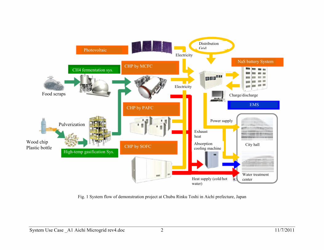
Fig. 1 System flow of demonstration project at Chubu Rinku Toshi in Aichi prefecture, Japan
Photovoltaic
CHP by MCFC
CHP by PAFC
CHP by SOFC
NaS battery System
CH4 fermentation sys.
High-temp gasification Sys.
EMS
Distribution Grid
Food scraps
Wood chip Plastic bottle
Pulverization
Electricity
Electricity
Exhaust heat
Heat supply (cold/hot water)
Power supply
City hall
Water treatment center
Charge/discharge
Absorption cooling machine
System Use Case _A1 Aichi Microgrid rev4.doc 3 11/7/2011
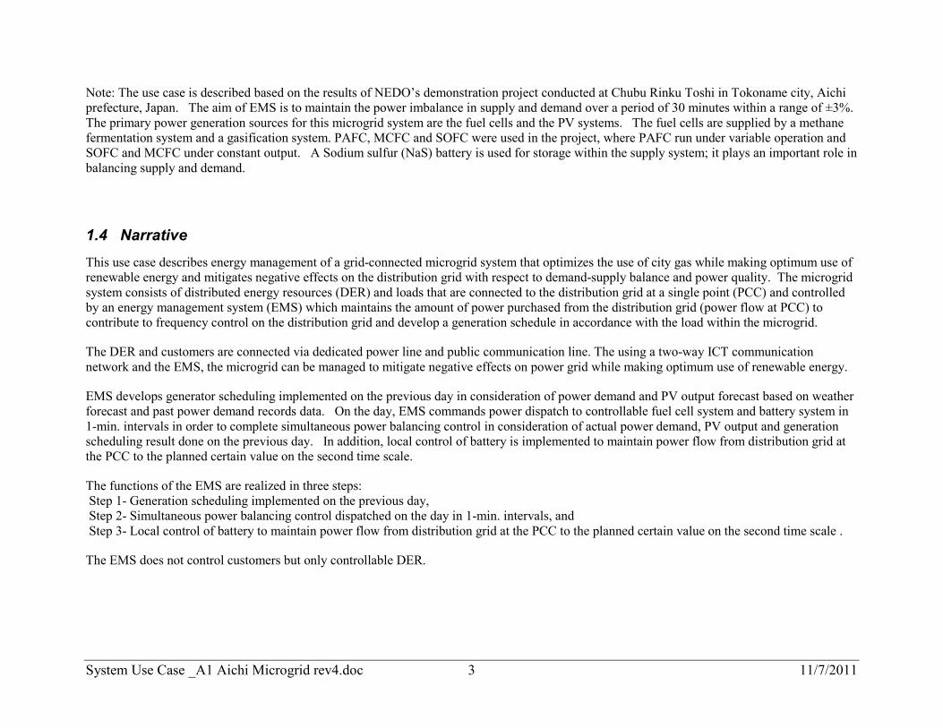
Note: The use case is described based on the results of NEDO’s demonstration project conducted at Chubu Rinku Toshi in Tokoname city, Aichi prefecture, Japan. The aim of EMS is to maintain the power imbalance in supply and demand over a period of 30 minutes within a range of ±3%. The primary power generation sources for this microgrid system are the fuel cells and the PV systems. The fuel cells are supplied by a methane fermentation system and a gasification system. PAFC, MCFC and SOFC were used in the project, where PAFC run under variable operation and SOFC and MCFC under constant output. A Sodium sulfur (NaS) battery is used for storage within the supply system; it plays an important role in balancing supply and demand.
1.4 Narrative This use case describes energy management of a grid-connected microgrid system that optimizes the use of city gas while making optimum use of renewable energy and mitigates negative effects on the distribution grid with respect to demand-supply balance and power quality. The microgrid system consists of distributed energy resources (DER) and loads that are connected to the distribution grid at a single point (PCC) and controlled by an energy management system (EMS) which maintains the amount of power purchased from the distribution grid (power flow at PCC) to contribute to frequency control on the distribution grid and develop a generation schedule in accordance with the load within the microgrid.
The DER and customers are connected via dedicated power line and public communication line. The using a two-way ICT communication network and the EMS, the microgrid can be managed to mitigate negative effects on power grid while making optimum use of renewable energy.
EMS develops generator scheduling implemented on the previous day in consideration of power demand and PV output forecast based on weather forecast and past power demand records data. On the day, EMS commands power dispatch to controllable fuel cell system and battery system in 1-min. intervals in order to complete simultaneous power balancing control in consideration of actual power demand, PV output and generation scheduling result done on the previous day. In addition, local control of battery is implemented to maintain power flow from distribution grid at the PCC to the planned certain value on the second time scale.
The functions of the EMS are realized in three steps: Step 1- Generation scheduling implemented on the previous day, Step 2- Simultaneous power balancing control dispatched on the day in 1-min. intervals, and Step 3- Local control of battery to maintain power flow from distribution grid at the PCC to the planned certain value on the second time scale .
The EMS does not control customers but only controllable DER.
System Use Case _A1 Aichi Microgrid rev4.doc 4 11/7/2011
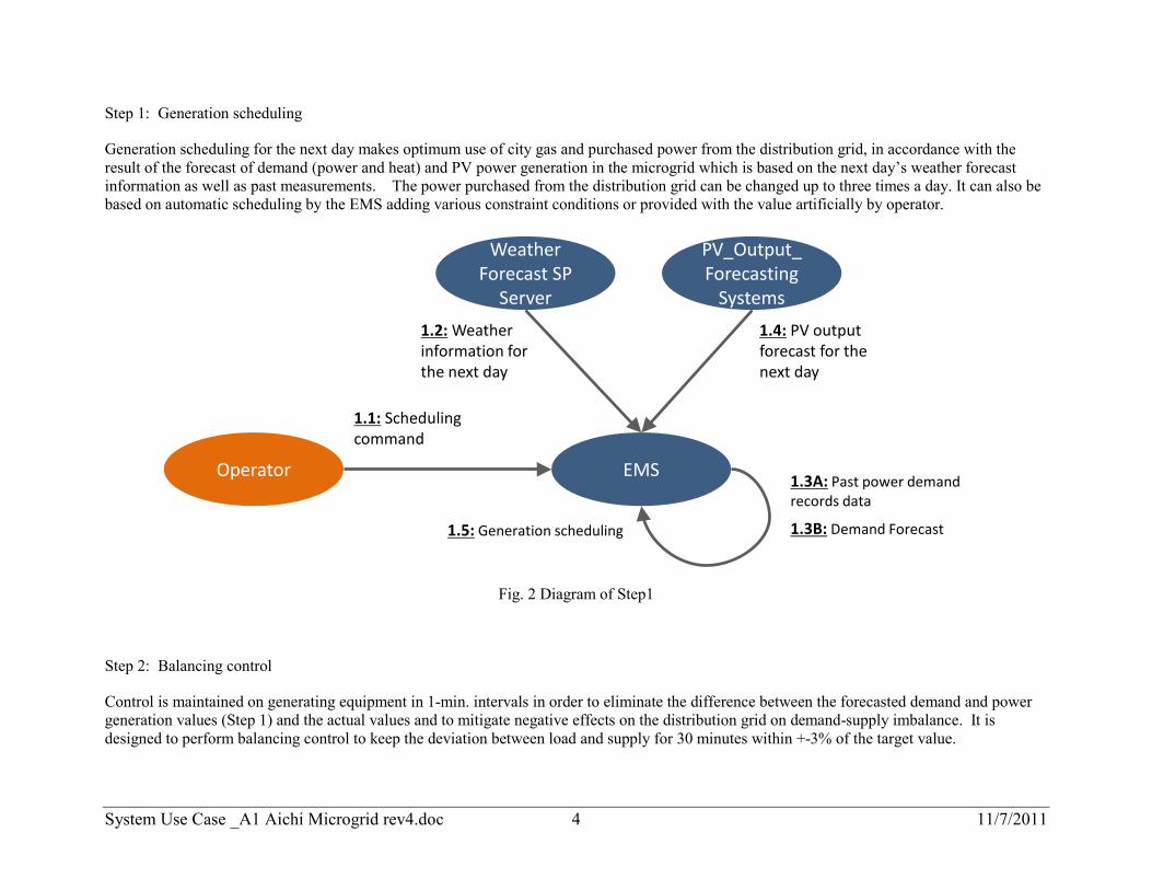
Step 1: Generation scheduling
Generation scheduling for the next day makes optimum use of city gas and purchased power from the distribution grid, in accordance with the result of the forecast of demand (power and heat) and PV power generation in the microgrid which is based on the next day’s weather forecast information as well as past measurements. The power purchased from the distribution grid can be changed up to three times a day. It can also be based on automatic scheduling by the EMS adding various constraint conditions or provided with the value artificially by operator.
EMSOperator
PV_Output_Forecasting
Systems
1.1: Scheduling command
1.4: PV output forecast for the next day
1.3A: Past power demand records data
1.5: Generation scheduling
Weather Forecast SP
Server
1.2: Weather information for the next day
1.3B: Demand Forecast
Fig. 2 Diagram of Step1
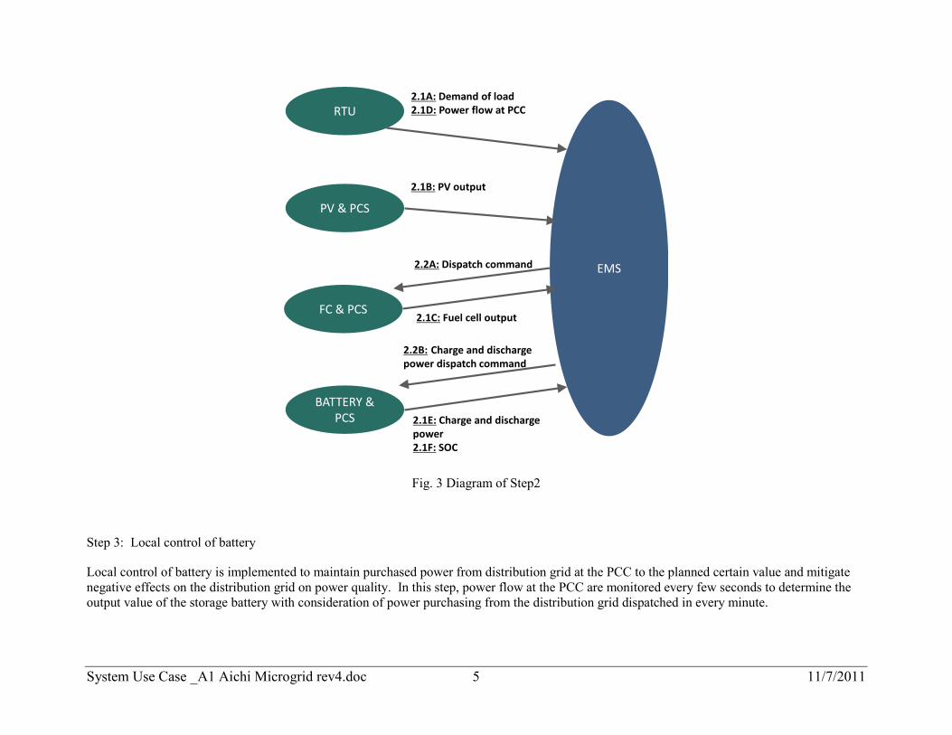
Step 2: Balancing control
Control is maintained on generating equipment in 1-min. intervals in order to eliminate the difference between the forecasted demand and power generation values (Step 1) and the actual values and to mitigate negative effects on the distribution grid on demand-supply imbalance. It is designed to perform balancing control to keep the deviation between load and supply for 30 minutes within +-3% of the target value.
System Use Case _A1 Aichi Microgrid rev4.doc 5 11/7/2011
RTU2.1A: Demand of load2.1D: Power flow at PCC
EMS
PV & PCS
2.1B: PV output
FC & PCS2.1C: Fuel cell output
BATTERY & PCS 2.1E: Charge and discharge
power2.1F: SOC
2.2A: Dispatch command
2.2B: Charge and discharge power dispatch command
Fig. 3 Diagram of Step2
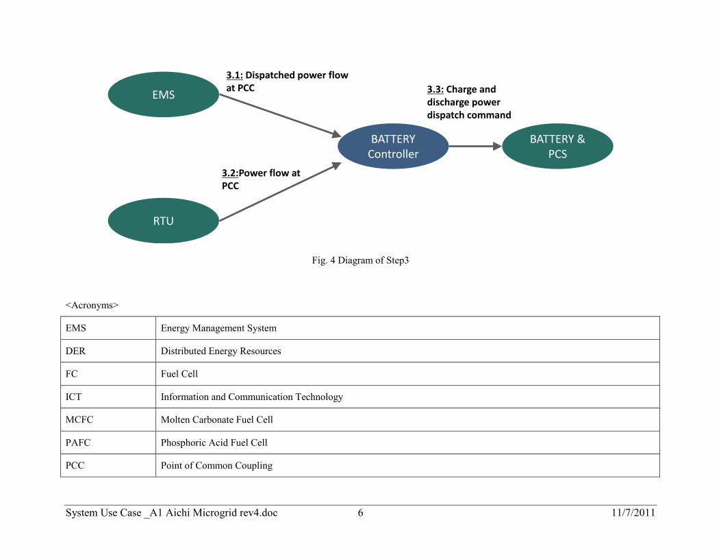
Step 3: Local control of battery
Local control of battery is implemented to maintain purchased power from distribution grid at the PCC to the planned certain value and mitigate negative effects on the distribution grid on power quality. In this step, power flow at the PCC are monitored every few seconds to determine the output value of the storage battery with consideration of power purchasing from the distribution grid dispatched in every minute.
System Use Case _A1 Aichi Microgrid rev4.doc 6 11/7/2011
RTU
3.2:Power flow at PCC
EMS
3.1: Dispatched power flow at PCC
BATTERY & PCS
3.3: Charge and discharge power dispatch command
BATTERY Controller
Fig. 4 Diagram of Step3
<Acronyms>
EMS Energy Management System
DER Distributed Energy Resources
FC Fuel Cell
ICT Information and Communication Technology
MCFC Molten Carbonate Fuel Cell
PAFC Phosphoric Acid Fuel Cell
PCC Point of Common Coupling
System Use Case _A1 Aichi Microgrid rev4.doc 7 11/7/2011
PCS Power Conditioning System
PV Photovoltaic
RTU Remote Terminal Unit
SOC State of Charge
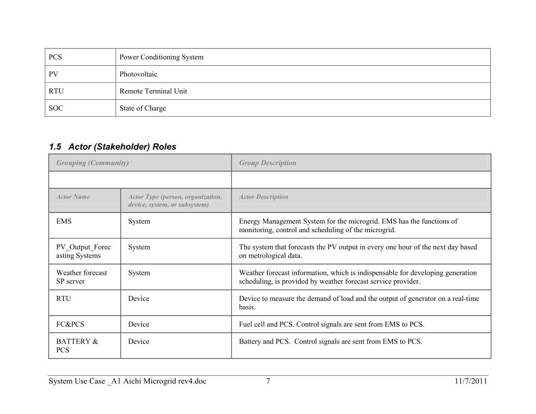
1.5 Actor (Stakeholder) Roles
Grouping (Community) , Group Description
Actor Name Actor Type (person, organization, device, system, or subsystem)
Actor Description
EMS System Energy Management System for the microgrid. EMS has the functions of monitoring, control and scheduling of the microgrid.
PV_Output_Forecasting Systems
System The system that forecasts the PV output in every one hour of the next day based on metrological data.
Weather forecast SP server
System Weather forecast information, which is indispensable for developing generation scheduling, is provided by weather forecast service provider.
RTU Device Device to measure the demand of load and the output of generator on a real-time basis.
FC&PCS Device Fuel cell and PCS. Control signals are sent from EMS to PCS.
BATTERY & PCS
Device Battery and PCS. Control signals are sent from EMS to PCS.
System Use Case _A1 Aichi Microgrid rev4.doc 8 11/7/2011
Grouping (Community) , Group Description
Actor Name Actor Type (person, organization, device, system, or subsystem)
Actor Description
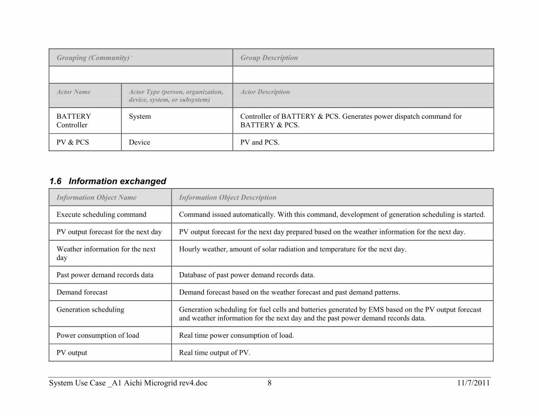
BATTERY Controller
System Controller of BATTERY & PCS. Generates power dispatch command for BATTERY & PCS.
PV & PCS Device PV and PCS.
1.6 Information exchanged
Information Object Name Information Object Description
Execute scheduling command Command issued automatically. With this command, development of generation scheduling is started.
PV output forecast for the next day PV output forecast for the next day prepared based on the weather information for the next day.
Weather information for the next day
Hourly weather, amount of solar radiation and temperature for the next day.
Past power demand records data Database of past power demand records data.
Demand forecast Demand forecast based on the weather forecast and past demand patterns.
Generation scheduling Generation scheduling for fuel cells and batteries generated by EMS based on the PV output forecast and weather information for the next day and the past power demand records data.
Power consumption of load Real time power consumption of load.
PV output Real time output of PV.
System Use Case _A1 Aichi Microgrid rev4.doc 9 11/7/2011
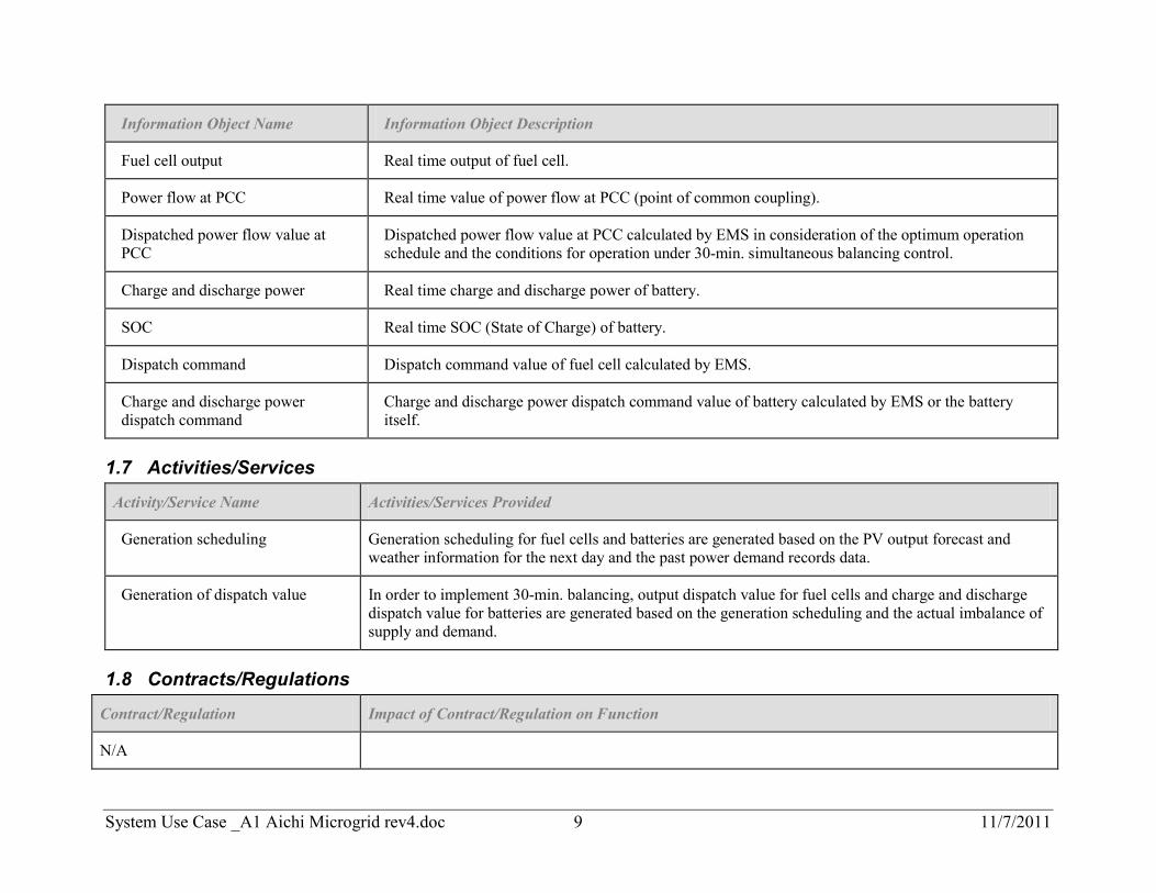
Information Object Name Information Object Description
Fuel cell output Real time output of fuel cell.
Power flow at PCC Real time value of power flow at PCC (point of common coupling).
Dispatched power flow value at PCC
Dispatched power flow value at PCC calculated by EMS in consideration of the optimum operation schedule and the conditions for operation under 30-min. simultaneous balancing control.
Charge and discharge power Real time charge and discharge power of battery.
SOC Real time SOC (State of Charge) of battery.
Dispatch command Dispatch command value of fuel cell calculated by EMS.
Charge and discharge power dispatch command
Charge and discharge power dispatch command value of battery calculated by EMS or the battery itself.
1.7 Activities/Services
Activity/Service Name Activities/Services Provided
Generation scheduling Generation scheduling for fuel cells and batteries are generated based on the PV output forecast and weather information for the next day and the past power demand records data.
Generation of dispatch value In order to implement 30-min. balancing, output dispatch value for fuel cells and charge and discharge dispatch value for batteries are generated based on the generation scheduling and the actual imbalance of supply and demand.
1.8 Contracts/Regulations
Contract/Regulation Impact of Contract/Regulation on Function
N/A
System Use Case _A1 Aichi Microgrid rev4.doc 10 11/7/2011
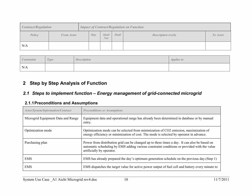
Contract/Regulation Impact of Contract/Regulation on Function
Policy From Actor May Shall Not
Shall Description (verb) To Actor
N/A
Constraint Type Description Applies to
N/A
2 Step by Step Analysis of Function
2.1 Steps to implement function – Energy management of grid-connected microgrid
2.1.1 Preconditions and Assumptions Actor/System/Information/Contract Preconditions or Assumptions
Microgrid Equipment Data and Range Equipment data and operational range has already been determined in database or by manual entry.
Optimization mode Optimization mode can be selected from minimization of CO2 emission, maximization of energy efficiency or minimization of cost. The mode is selected by operator in advance.
Purchasing plan Power from distribution grid can be changed up to three times a day. It can also be based on automatic scheduling by EMS adding various constraint conditions or provided with the value artificially by operator.
EMS EMS has already prepared the day’s optimum generation schedule on the previous day.(Step 1)
EMS EMS dispatches the target value for active power output of fuel cell and battery every minute to
System Use Case _A1 Aichi Microgrid rev4.doc 11 11/7/2011
Actor/System/Information/Contract Preconditions or Assumptions
implement 30-min. balancing based on the actual demand and generation results, the records of power purchase from distribution grid and the SOC of battery.
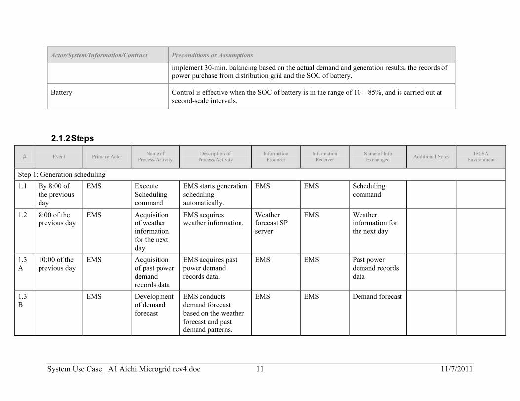
Battery Control is effective when the SOC of battery is in the range of 10 – 85%, and is carried out at second-scale intervals.
2.1.2 Steps
# Event Primary Actor Name of Process/Activity
Description of Process/Activity
Information Producer
Information Receiver
Name of Info Exchanged Additional Notes IECSA
Environment
Step 1: Generation scheduling 1.1 By 8:00 of
the previous day
EMS Execute Scheduling command
EMS starts generation scheduling automatically.
EMS EMS Scheduling command
1.2 8:00 of the previous day
EMS Acquisition of weather information for the next day
EMS acquires weather information.
Weather forecast SP server
EMS Weather information for the next day
1.3A
10:00 of the previous day
EMS Acquisition of past power demand records data
EMS acquires past power demand records data.
EMS EMS Past power demand records data
1.3B
EMS Development of demand forecast
EMS conducts demand forecast based on the weather forecast and past demand patterns.
EMS EMS Demand forecast
System Use Case _A1 Aichi Microgrid rev4.doc 12 11/7/2011
# Event Primary Actor Name of Process/Activity
Description of Process/Activity
Information Producer
Information Receiver
Name of Info Exchanged Additional Notes IECSA
Environment
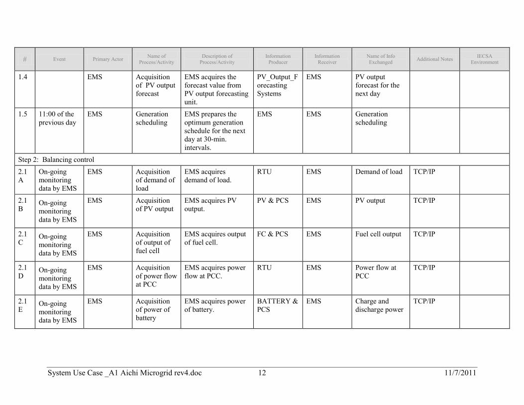
1.4 EMS Acquisition of PV output forecast
EMS acquires the forecast value from PV output forecasting unit.
PV_Output_Forecasting Systems
EMS PV output forecast for the next day
1.5 11:00 of the previous day
EMS Generation scheduling
EMS prepares the optimum generation schedule for the next day at 30-min. intervals.
EMS EMS Generation scheduling
Step 2: Balancing control
2.1A
On-going monitoring data by EMS
EMS Acquisition of demand of load
EMS acquires demand of load.
RTU EMS Demand of load TCP/IP
2.1B
On-going monitoring data by EMS
EMS Acquisition of PV output
EMS acquires PV output.
PV & PCS EMS PV output TCP/IP
2.1C
On-going monitoring data by EMS
EMS Acquisition of output of fuel cell
EMS acquires output of fuel cell.
FC & PCS EMS Fuel cell output TCP/IP
2.1D
On-going monitoring data by EMS
EMS Acquisition of power flow at PCC
EMS acquires power flow at PCC.
RTU EMS Power flow at PCC
TCP/IP
2.1E
On-going monitoring data by EMS
EMS Acquisition of power of battery
EMS acquires power of battery.
BATTERY & PCS
EMS Charge and discharge power
TCP/IP
System Use Case _A1 Aichi Microgrid rev4.doc 13 11/7/2011
# Event Primary Actor Name of Process/Activity
Description of Process/Activity
Information Producer
Information Receiver
Name of Info Exchanged Additional Notes IECSA
Environment
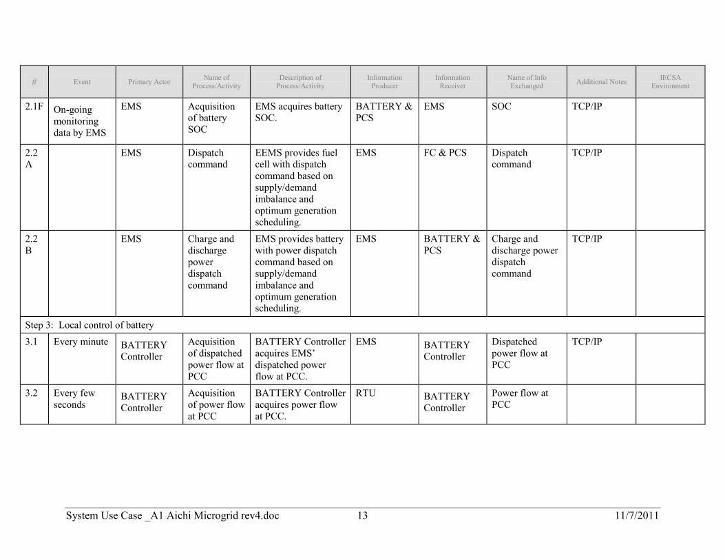
2.1F On-going monitoring data by EMS
EMS Acquisition of battery SOC
EMS acquires battery SOC.
BATTERY & PCS
EMS SOC TCP/IP
2.2A
EMS Dispatch command
EEMS provides fuel cell with dispatch command based on supply/demand imbalance and optimum generation scheduling.
EMS FC & PCS Dispatch command
TCP/IP
2.2B
EMS Charge and discharge power dispatch command
EMS provides battery with power dispatch command based on supply/demand imbalance and optimum generation scheduling.
EMS BATTERY & PCS
Charge and discharge power dispatch command
TCP/IP
Step 3: Local control of battery
3.1 Every minute BATTERY Controller
Acquisition of dispatched power flow at PCC
BATTERY Controller acquires EMS’ dispatched power flow at PCC.
EMS BATTERY Controller
Dispatched power flow at PCC
TCP/IP
3.2 Every few seconds
BATTERY Controller
Acquisition of power flow at PCC
BATTERY Controller acquires power flow at PCC.
RTU BATTERY Controller
Power flow at PCC
System Use Case _A1 Aichi Microgrid rev4.doc 14 11/7/2011
# Event Primary Actor Name of Process/Activity
Description of Process/Activity
Information Producer
Information Receiver
Name of Info Exchanged Additional Notes IECSA
Environment
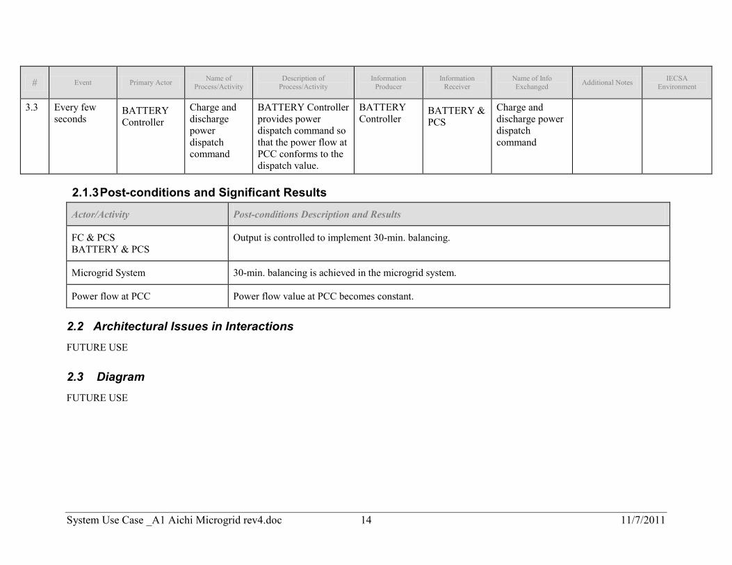
3.3 Every few seconds
BATTERY Controller
Charge and discharge power dispatch command
BATTERY Controller provides power dispatch command so that the power flow at PCC conforms to the dispatch value.
BATTERY Controller
BATTERY & PCS
Charge and discharge power dispatch command
2.1.3 Post-conditions and Significant Results
Actor/Activity Post-conditions Description and Results
FC & PCS BATTERY & PCS
Output is controlled to implement 30-min. balancing.
Microgrid System 30-min. balancing is achieved in the microgrid system.
Power flow at PCC Power flow value at PCC becomes constant.
2.2 Architectural Issues in Interactions FUTURE USE
2.3 Diagram FUTURE USE
System Use Case _A1 Aichi Microgrid rev4.doc 15 11/7/2011
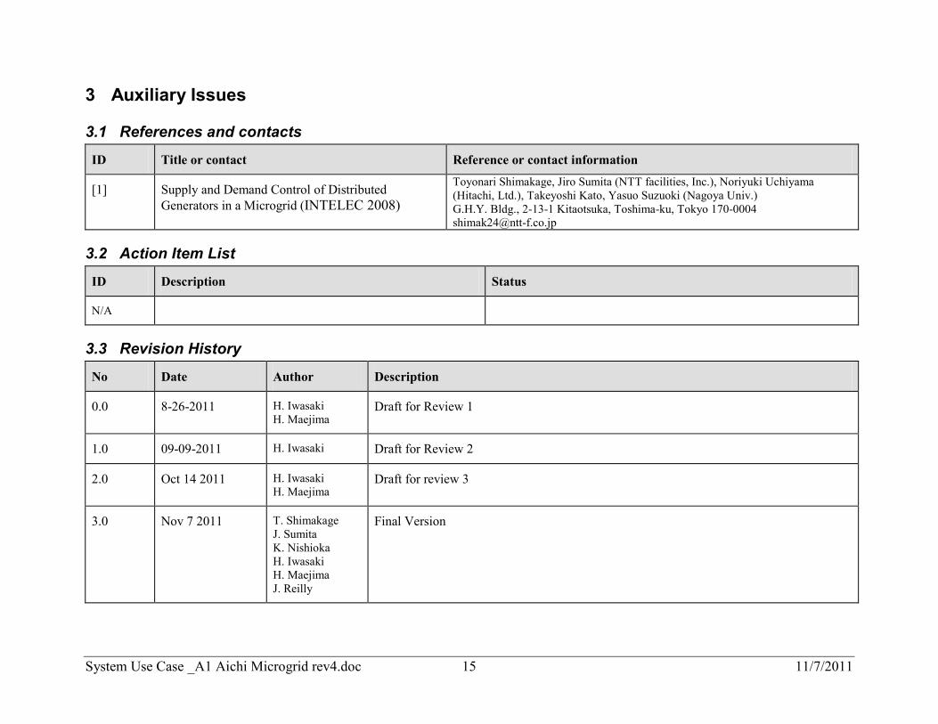
3 Auxiliary Issues
3.1 References and contacts
ID Title or contact Reference or contact information
[1] Supply and Demand Control of Distributed Generators in a Microgrid (INTELEC 2008)
Toyonari Shimakage, Jiro Sumita (NTT facilities, Inc.), Noriyuki Uchiyama (Hitachi, Ltd.), Takeyoshi Kato, Yasuo Suzuoki (Nagoya Univ.) G.H.Y. Bldg., 2-13-1 Kitaotsuka, Toshima-ku, Tokyo 170-0004 [email protected]
3.2 Action Item List
ID Description Status
N/A
3.3 Revision History
No Date Author Description
0.0 8-26-2011 H. Iwasaki H. Maejima
Draft for Review 1
1.0 09-09-2011 H. Iwasaki Draft for Review 2
2.0 Oct 14 2011 H. Iwasaki H. Maejima
Draft for review 3
3.0 Nov 7 2011 T. Shimakage J. Sumita K. Nishioka H. Iwasaki H. Maejima J. Reilly
Final Version