Embed Size (px)
Citation preview

1
DIRECT METHANOL FUEL CELL WITHDIRECT METHANOL FUEL CELL WITHEXTENDED REACTION ZONE ANODEEXTENDED REACTION ZONE ANODE
Alex Bauer, Elöd L. Gyenge and Colin W. OlomanAlex Bauer, Elöd L. Gyenge and Colin W. Oloman
Department of Chemical and Biological EngineeringDepartment of Chemical and Biological EngineeringThe University of British Columbia, Vancouver, CanadaThe University of British Columbia, Vancouver, Canada
Presented by: Alex BauerPresented by: Alex BauerDate: 2Date: 2ndnd of November 2006 of November 2006
210210thth Meeting of The Electrochemical Society Meeting of The Electrochemical Society Cancun, MexicoCancun, Mexico

2
Anode reaction: CH3OH + H2O CO2 + 6H+ + 6e- E0a= 0.04 V @ 298 K @ 298 K
Methanol:Methanol: -- cheap (ca. 200 $ US/t) cheap (ca. 200 $ US/t) - easy handling, storage and distribution - easy handling, storage and distribution
- simple fuel cell design and operation- simple fuel cell design and operation
DMFCs for portable applications DMFCs for portable applications (and transportation)(and transportation)
FuelFuel Volumetric Energy DensityVolumetric Energy Density
kWh lkWh l-1-1
Hydrogen (30 MPa)Hydrogen (30 MPa) 0.750.75
Hydrogen (liquid, T=20K)Hydrogen (liquid, T=20K) 2.362.36
GasolineGasoline 8.768.76
MethanolMethanol 4.424.42
[1] W. Zittel, R. Wurster, HyWeb: Knowledge – Hydrogen in the Energy Sector http://www.hydrogen.org/Knowledge/w-i-energiew-eng2.html
[1][1]

3
Sluggish anode reaction Development of novel catalysts (ternary and quaternary compositions)
Enhancing active catalyst area (nanoparticle – support interaction)
Methanol cross-over Modified membranes
CO2 accumulation Hydrophobic channels (PTFE addition)
Alternative flow designs (e.g. mesh flow beds)
Novel electrode designs
Current challenges and potential solutionsCurrent challenges and potential solutions
OUR APPROACH: Application of porous 3D catalyzed graphite felt electrode with high specific surface area

4
Recent developments for DMFC anode designsRecent developments for DMFC anode designs
[2] [2] G. S. Chai et al., J. Phys. Chem. B, 108, 7076 (2004)G. S. Chai et al., J. Phys. Chem. B, 108, 7076 (2004)
[3][3] R. G. Allen et al., J. Power Sources, 143, 145 (2005)R. G. Allen et al., J. Power Sources, 143, 145 (2005)
Carbon
Ti mesh
500 nm500 nm 100 nm100 nm
PtRu particlesPtRu particlesd = 2 - 3 nmd = 2 - 3 nm
PtRu particlesPtRu particlesd d 5 nm 5 nm

5
DMFC with conventional anodeDMFC with conventional anode
Anode reaction: CH3OH + H2O → CO2 + 6H+ + 6e-
Cathode reaction: 1.5O2 + 6H+ + 6e- → 3H2O
CH3OH (l)
O2 (g)
H+
e-
15-50m
100-300m
endplate
diffusionlayer
catalystlayer
membrane

6
DMFC with novel 3D anodeDMFC with novel 3D anode
Anode reaction: CH3OH + H2O → CO2 + 6H+ + 6e-
CH3OH (l)
H+
100-200mdepending on compression
O2 (g)
e-
catalyzedgraphite
felt
Cathode reaction: 1.5O2 + 6H+ + 6e- → 3H2O

7
2-15 nm2-15 nm
[4][4] B. Gollas et al., Electrochimica Acta, 45 (22), 3712 & 3721 (2000) B. Gollas et al., Electrochimica Acta, 45 (22), 3712 & 3721 (2000)
[4][4]
Surfactant assisted electrodeposition to Surfactant assisted electrodeposition to obtain porous catalyst depositsobtain porous catalyst deposits
[5][5] A. Bauer et al., Electrochimica Acta, 51 (25), 5359 (2006) A. Bauer et al., Electrochimica Acta, 51 (25), 5359 (2006)
Without surfactant With surfactant
Smooth substrate
3D graphite substrate
[5][5][5][5]

8
Surfactant assisted galvanostatic deposition Surfactant assisted galvanostatic deposition of nanoparticles on 3D substrateof nanoparticles on 3D substrate
graphite feltsubstrate
+
-
DC powersupply
platinized Titanium anodes
graphite felt (cathode)
plexiglass cell containingplating solution
plastic mesh separator
0.95, d 350 m, as 104 m-1
[6][6] A. Bauer et al., Electrochimica Acta, 51 (25), 5358 (2006) A. Bauer et al., Electrochimica Acta, 51 (25), 5358 (2006)
[6][6]

9
Research objectivesResearch objectives
Surfactant mediated electrodeposition of PtRu and Surfactant mediated electrodeposition of PtRu and PtRuMoPtRuMo catalyst on graphite feltcatalyst on graphite felt
Analysis of deposit morphology, weight, composition Analysis of deposit morphology, weight, composition and active surface area (SEM, ICP_AES, Cu upd)and active surface area (SEM, ICP_AES, Cu upd)
Assessment of catalytic activity for methanol oxidation Assessment of catalytic activity for methanol oxidation (CV,CP,CA)(CV,CP,CA)
Fuel cell testingFuel cell testing
Overall Overall ggoal:oal: Assess feasibility of employing catalyzed graphite felt asAssess feasibility of employing catalyzed graphite felt as DMFC anode for liquid feed operation. DMFC anode for liquid feed operation.

10
Results - SEMResults - SEM
High resolution SEM micrograph of PtRu catalyst deposited High resolution SEM micrograph of PtRu catalyst deposited on graphite by surfactant assisted galvanostatic platingon graphite by surfactant assisted galvanostatic plating
► ◄ ► ◄ ~ 50 nm~ 50 nm

11
Results – Cyclic voltammetryResults – Cyclic voltammetry
Scan rate = 5 mV sScan rate = 5 mV s-1-1, 0.5 M CH, 0.5 M CH33OH - 0.1 M HOH - 0.1 M H22SOSO44
-0.8 -0.6 -0.4 -0.2 0.0 0.2 0.4 0.6
i [m
A c
m-2
]
-50
0
50
100
150
200
250PtRu (2.4:1) T = 298 KPtRu (2.4:1) T = 343 KPtRuMo (2.1:1:0.1) T = 298 KPtRuMo (2.1:1:0.1) T = 343 K
E [V vs. MSE]

12
t [s]
0 20 40 60 80 100 120 140 160 180 200
E [
V v
s. M
SE
]
-0.55
-0.50
-0.45
-0.40
-0.35
-0.30
-0.25
PtRu (2.4:1) T = 298 KPtRu (2.4:1) T = 343 KPtRuMo (2.1:1:0.1) T = 298 KPtRuMo (2.1:1:0.1) T = 343 K
Results – ChronopotentiometryResults – Chronopotentiometry
Current = 5 mA cmCurrent = 5 mA cm-2-2, 0.5 M CH, 0.5 M CH33OH - 0.1 M HOH - 0.1 M H22SOSO44

13
Results – FC tests: Novel 3D anode vs. Results – FC tests: Novel 3D anode vs. conventional gas diffusion electrode (GDE)conventional gas diffusion electrode (GDE)
Anode: 1 M CHAnode: 1 M CH33OH - 0.5 M HOH - 0.5 M H22SOSO44, , 5 ml min5 ml min-1-1, ambient pressure , ambient pressure
Cathode: dry OCathode: dry O22, 500 ml min, 500 ml min-1-1 STP, 2 atm STP, 2 atm
i [mA cm-2]
0 100 200 300 400 500
E [
V]
0.1
0.2
0.3
0.4
0.5
0.6
0.7
0.8
PtRu (2.4:1) 3.2 mg cm-2 (graphite felt)PtRu (1:1) 4.0 mg cm-2 (GDE)
T = 333 K

14
Anode: 1 M CHAnode: 1 M CH33OH - 0.5 M HOH - 0.5 M H22SOSO44, , 5 ml min5 ml min-1-1, ambient pressure , ambient pressure
Cathode: dry OCathode: dry O22, 500 ml min, 500 ml min-1-1 STP, 2 atm STP, 2 atm
i [mA cm-2]
0 100 200 300 400 500
p [
mW
cm
-2]
0
20
40
60
80
100
120
140
160
PtRu (2.4:1) 3.2 mg cm-2 (graphite felt)
PtRu (1:1) 4.0 mg cm-2 (GDE)
T = 333 K
Results – FC tests: Novel 3D anode vs. Results – FC tests: Novel 3D anode vs. conventional gas diffusion electrode (GDE)conventional gas diffusion electrode (GDE)
15
Anode: 1 M CHAnode: 1 M CH33OH - 0.5 M HOH - 0.5 M H22SOSO44, , 5 ml min5 ml min-1-1, ambient pressure , ambient pressure
Cathode: dry OCathode: dry O22, 500 ml min, 500 ml min-1-1 STP, 2 atm STP, 2 atm
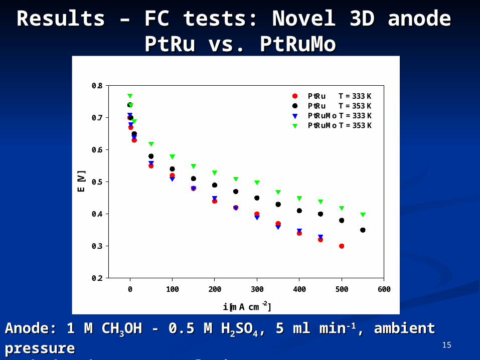
Results – FC tests: Novel 3D anode Results – FC tests: Novel 3D anode PtRu vs. PtRuMoPtRu vs. PtRuMo
i [mA cm-2]
0 100 200 300 400 500 600
E [
V]
0.2
0.3
0.4
0.5
0.6
0.7
0.8PtRu T = 333 KPtRu T = 353 KPtRuMo T = 333 KPtRuMo T = 353 K
16
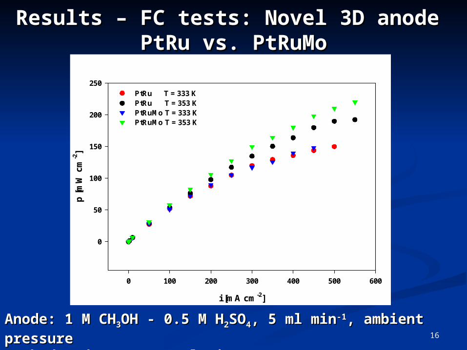
Anode: 1 M CHAnode: 1 M CH33OH - 0.5 M HOH - 0.5 M H22SOSO44, , 5 ml min5 ml min-1-1, ambient pressure , ambient pressure
Cathode: dry OCathode: dry O22, 500 ml min, 500 ml min-1-1 STP, 2 atm STP, 2 atm
i [mA cm-2]
0 100 200 300 400 500 600
p [
mW
cm
-2]
0
50
100
150
200
250PtRu T = 333 KPtRu T = 353 KPtRuMo T = 333 KPtRuMo T = 353 K
Results – FC tests: Novel 3D anode Results – FC tests: Novel 3D anode PtRu vs. PtRuMoPtRu vs. PtRuMo
17
gel: 1 M H2SO4, 5 %wt SiO2
t [min]
0 20 40 60 80 100 120 140 160 180 200
E [
V]
0.34
0.36
0.38
0.40
0.42
0.44
0.46PtRuPtRuMo
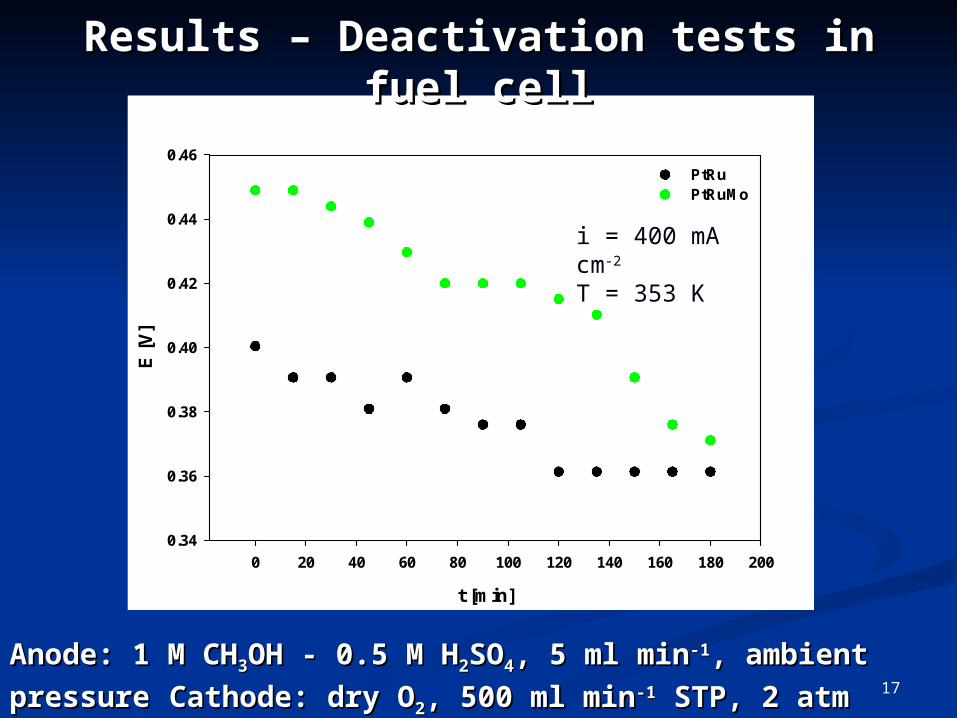
Results – Deactivation tests in fuel cellResults – Deactivation tests in fuel cell
Anode: 1 M CHAnode: 1 M CH33OH - 0.5 M HOH - 0.5 M H22SOSO44, , 5 ml min5 ml min-1-1, ambient pressure, ambient pressure Cathode: dry OCathode: dry O22, 500 ml min, 500 ml min-1-1 STP, 2 atm STP, 2 atm
i = 400 mA cm-2
T = 353 K

18
[7][7] C. Coutanceau et al., J. Appl. Electrochem., 34, 64 (2004) C. Coutanceau et al., J. Appl. Electrochem., 34, 64 (2004)[8][8] G. S. Chai et al., J. Phys. Chem. B, 108, 7078 (2004) G. S. Chai et al., J. Phys. Chem. B, 108, 7078 (2004)[9][9] R. G. Allen et al., J. Power Sources, 143, 148 (2005) R. G. Allen et al., J. Power Sources, 143, 148 (2005)
Comparison of fuel cell performanceComparison of fuel cell performancewith standard MEA and published data with standard MEA and published data
mas
s ac
tivi
ty [
mA
mg
PtR
u-1
]
0
20
40
60
80
100
120
140
160
catalyzed graphite felt
conv.GDE
VulcanXC-72 /C cloth
[7]
nano- porouscarbon
[8]
Anode catalyst support type:
Timesh
[9]
333 K 343 K 353 K 333 K 333 K 343 K 363 K
Cell voltage = 0.4 V

19
Conclusions and outlookConclusions and outlook
Obtained highly dispersed nanoparticles on 3D substrateObtained highly dispersed nanoparticles on 3D substrate Improved performance compared to conventional GDEImproved performance compared to conventional GDE (e.g. power output increased by 38 % at 300 mA cm(e.g. power output increased by 38 % at 300 mA cm-2-2)) Proof of concept for novel electrode designProof of concept for novel electrode design
Future work:Future work:
Optimize FC operation conditions Optimize FC operation conditions (experimental design)(experimental design) Develop ionic conductor networkDevelop ionic conductor network Improve long term performance - especially for PtRuMoImprove long term performance - especially for PtRuMo (e.g. catalyst regeneration after 2 h)(e.g. catalyst regeneration after 2 h)

20
The authors gratefully acknowledge the financial support The authors gratefully acknowledge the financial support of the BC Advanced Systems Institute and the Natural of the BC Advanced Systems Institute and the Natural
Sciences and Engineering Research Council of Canada. Sciences and Engineering Research Council of Canada.
AcknowledgementsAcknowledgements