Embed Size (px)
Citation preview
1
DISTILLATION CONTROLDISTILLATION CONTROL
Dr. Prakash KarpeDr. Prakash KarpeControl & Elec. Eng. Supt.Control & Elec. Eng. Supt.
ConocoPhillipsConocoPhillips
San Francisco Refinery, RodeoSan Francisco Refinery, Rodeo
2
D
B
L
R = L/DF
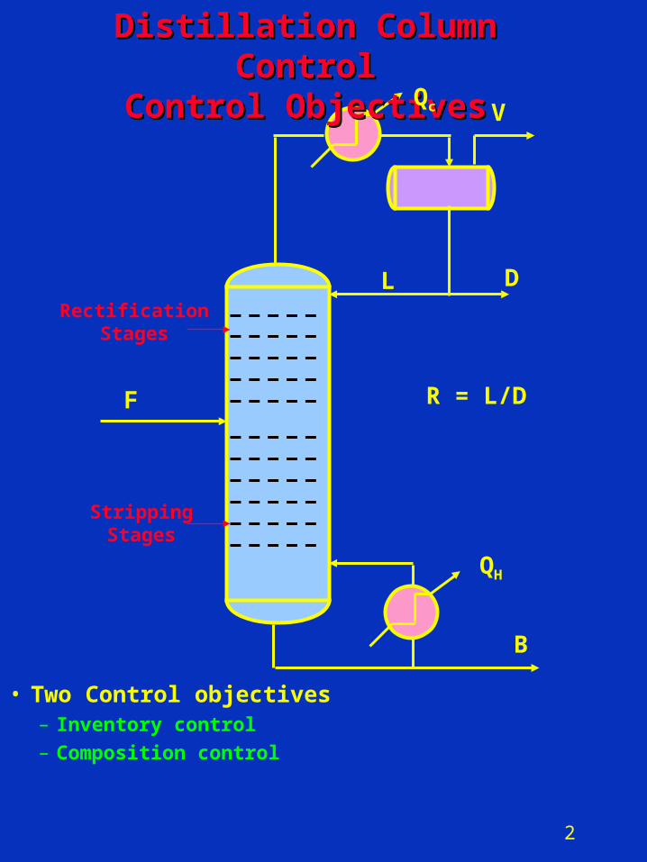
Distillation Column ControlDistillation Column ControlControl ObjectivesControl Objectives
V
RectificationStages
StrippingStages
QH
Qc
• Two Control objectives– Inventory control
– Composition control
3
Degrees of Freedom AnalysisDegrees of Freedom Analysis
• From control perspective, degrees of freedom of a process is defined as number of variables that can or must be controlled.– Helps to avoid over- or under-control of
processes.
• Degrees of freedom (to control) = No. of rationally placed control valves– A control valve represents a
manipulated variable (MV)

4
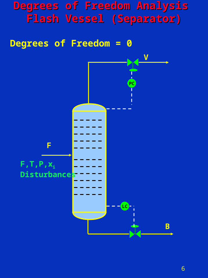
Degrees of Freedom Analysis Degrees of Freedom Analysis Flash Vessel (Separator)Flash Vessel (Separator)
V
B
F
F,T,P,xi
Disturbances
5
Inventory ControlInventory Control
• For steady state operation of a process, all inventories must be controlled– Vapor inventories are maintained by
pressure control– Liquid inventories are maintained by
level control
6
Degrees of Freedom Analysis Degrees of Freedom Analysis Flash Vessel (Separator)Flash Vessel (Separator)
V
B
F
F,T,P,xi
Disturbances
LC
PC
Degrees of Freedom = 0

7
F
LC
D
B
L
V
QH
PC
Degrees of Freedom AnalysisDegrees of Freedom AnalysisTypical Distillation ColumnTypical Distillation Column
Inventory ControlInventory Control
Degrees of Freedom = 3
LD
LB
TD
TB
8
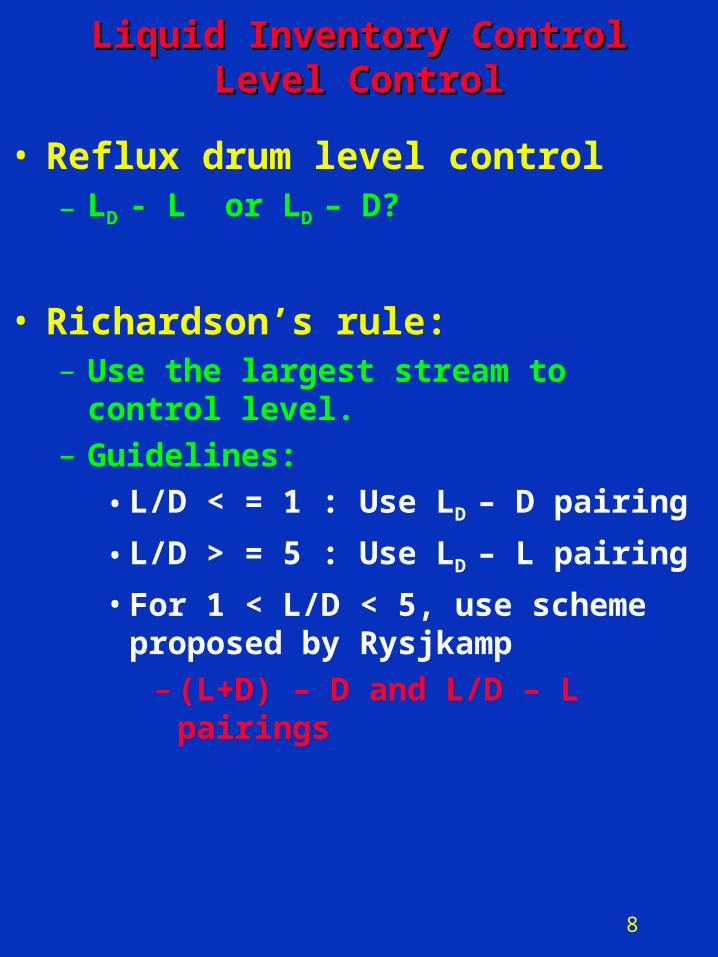
Liquid Inventory ControlLiquid Inventory ControlLevel ControlLevel Control
• Reflux drum level control– LD - L or LD – D?
• Richardson’s rule:– Use the largest stream to control level.– Guidelines:
• L/D < = 1 : Use LD – D pairing
• L/D > = 5 : Use LD – L pairing
• For 1 < L/D < 5, use scheme proposed by Rysjkamp
– (L+D) – D and L/D – L pairings
9
Two Common Level Control SchemesTwo Common Level Control Schemes
• Level control dilemma– Tight flow control?
• Oscillating level
– Tight level control?• Oscillating product flow
• Averaging or nonlinear level control
• Tight level control
10
Common Level Control SchemesCommon Level Control Schemes
• Averaging (nonlinear) level control– Used when product is a feed to a
downstream process• Examples
– Train of lightends columns– Reflux drum level control
• Tight level control– Used when product goes to tankage or a
surge drum or process requires low hold up
• Use P-only controller with KC = 4• Examples
– Reboiler level control– FCC Main Frac and Vacuum
column bottoms (coking concern)– Dirty wash oil draw level control
• Control hydrostatic P in the draw line
11
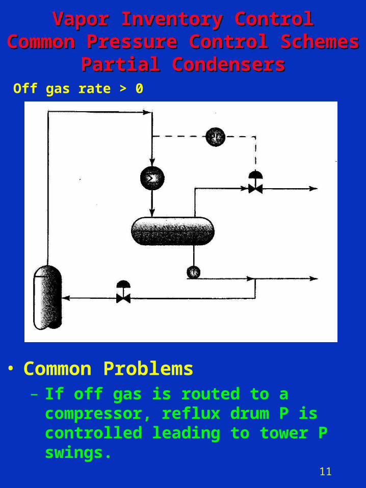
• Common Problems– If off gas is routed to a compressor,
reflux drum P is controlled leading to tower P swings.
Vapor Inventory ControlVapor Inventory ControlCommon Pressure Control SchemesCommon Pressure Control Schemes
Partial CondensersPartial CondensersOff gas rate > 0
12
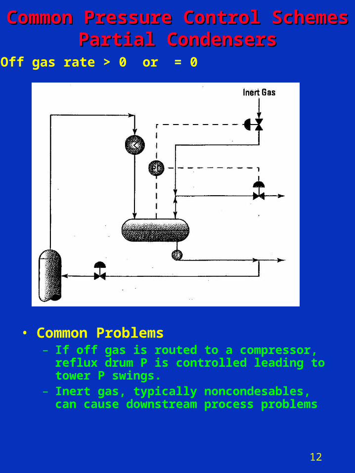
Common Pressure Control SchemesCommon Pressure Control SchemesPartial CondensersPartial Condensers
• Common Problems– If off gas is routed to a compressor, reflux
drum P is controlled leading to tower P swings.
– Inert gas, typically noncondesables, can cause downstream process problems
Off gas rate > 0 or = 0
13
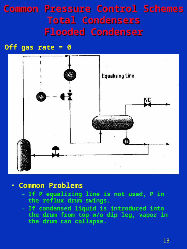
Common Pressure Control SchemesCommon Pressure Control SchemesTotal CondensersTotal Condensers
Flooded CondenserFlooded Condenser
Off gas rate = 0
• Common Problems– If P equalizing line is not used, P in the reflux
drum swings.– If condensed liquid is introduced into the drum
from top w/o dip leg, vapor in the drum can collapse.
14
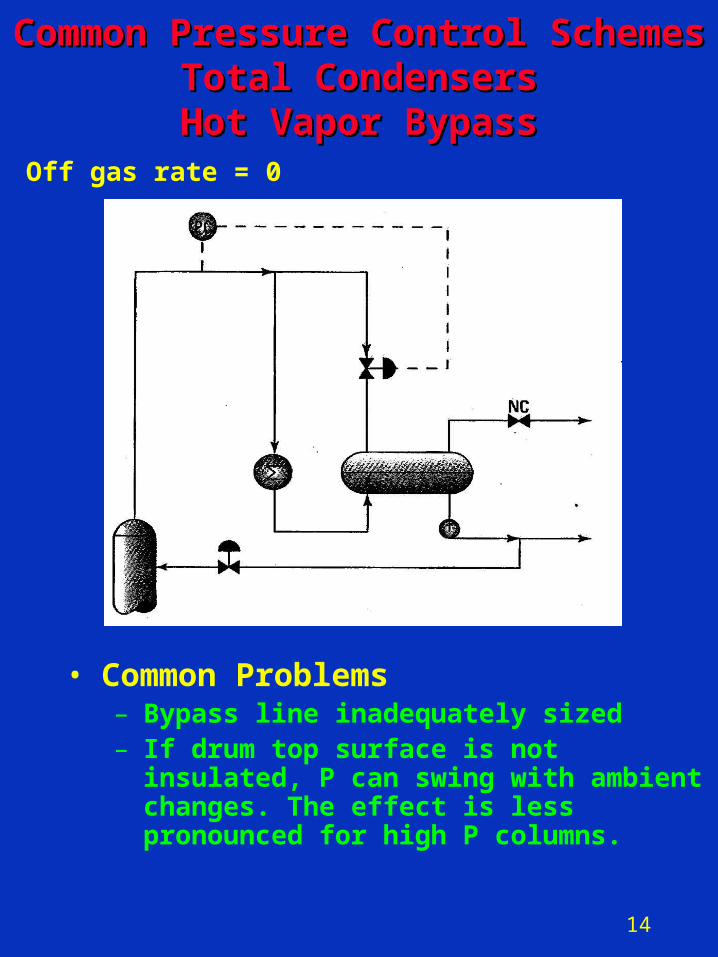
Off gas rate = 0
Common Pressure Control SchemesCommon Pressure Control SchemesTotal CondensersTotal CondensersHot Vapor BypassHot Vapor Bypass
• Common Problems– Bypass line inadequately sized– If drum top surface is not insulated, P can
swing with ambient changes. The effect is less pronounced for high P columns.
15
F
LC
D
B
L
V
QH
PC
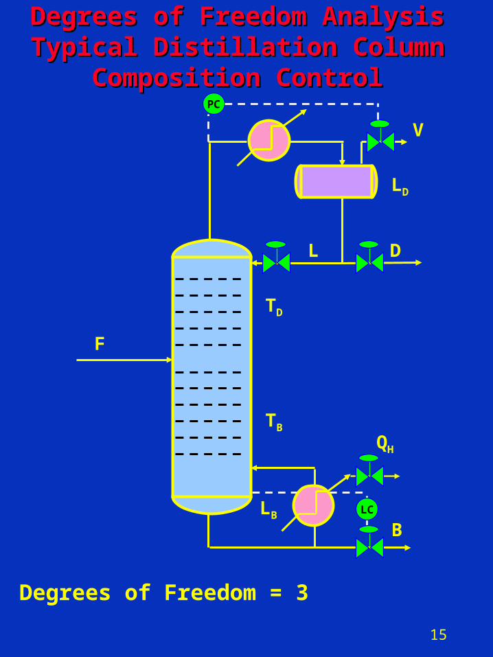
Degrees of Freedom AnalysisDegrees of Freedom AnalysisTypical Distillation ColumnTypical Distillation Column
Composition ControlComposition Control
Degrees of Freedom = 3
LD
LB
TD
TB
16
Composition Control ProblemComposition Control Problem
• Number of MV’s = 3– Reflux flow: L– Distillate flow: D– Reboiler heat: QH
– Reflux ratio– Product/ feed ratio– Steam/ feed ratio
• Need three controlled variables (CV’s)
• Possible CV’s– Reflux drum level: LD
– Distillate composition: xD – Appropriate temperature in rectification
section (TD)– Bottoms composition: xB – Appropriate temperature in stripping
section (TB)
• Control problem– How do we pair CV’s and MV’s?
17
Composition ControlComposition Control• Fundamental manipulated variables
– Feed split or cutpoint variable• Fraction of the feed that is taken
overhead of out of the bottom– Increasing distillate flow will
increase bottom purity and decrease distillate purity, etc.
– Fractionation variable• Energy that is put into the column to
achieve separation– Increasing the reflux ratio or the
reboiler duty will increase both distillate and bottoms purity
– Feed split has more pronounced impact on product purity than fractionation variable (exception low purity, < 90%, products)
– It is almost impossible to control any composition in the column if the feed split is fixed.
18
Manipulation of Fundamental Variables Manipulation of Fundamental Variables for Composition Controlfor Composition Control
• Fractionation Variables– L/D
– QH/ F (steam to feed ratio)
– L/F• High purity columns or dual product
purity columns• DeC3’s, DeC4’s, DIB’s, etc.
• Feed Split Variables– D or B flow (direct control scheme)
• FCC Main Fracs, Crude and Vacuum column side cuts
– L or QH (indirect control scheme)
• Level adjusts the product flow indirectly

19
Controlled Variables for Controlled Variables for Composition ControlComposition Control
• Stage temperature (Inferential control)
– Useless for ij < 1.2
• Online analyzer
– High economic gains
– ij < 1.2
• Temperature control – Special cases
– Difficult separations ( 1.2 < ij < 1.5)
• Flat temperature profiles
• Use differential temperatures ( T = Tm – Tk) between stages for control
• Example – HVGO quality control
– Extremely easy separations (high ij)
• Nonlinear in nature
• Steep temperature profile
• Use temperature profile control
• Tavg = (Tk + Tm)/ 2 , etc.
20
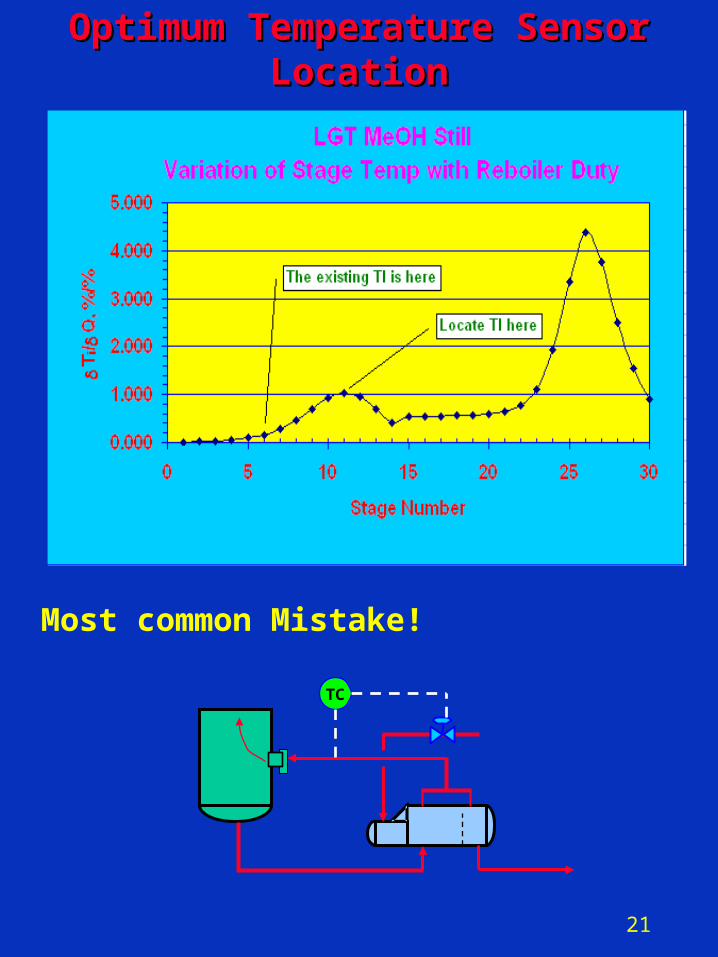
• Locate TI on the stage whose temperature shows maximum sensitivity to one of the available MV’s
– From simulation calculate (Ti / D)L,B, (Ti / L)D,B , (Ti / )L,D and
(Ti / Q)L,D where Ti is the temperature of stage i. Locate TI at the stage where (Ti / D)L,B , etc., is maximum.
• For calculating the derivatives, vary B, D, L and Q in the column specs only by small amount, e.g., by +0.5% and -0.5%. Calculate average derivative.
• Scale each variable by dividing it by its span in order to calculate the derivatives. The derivative will be a dimensionless number.
• Use high precision numbers
Composition ControlComposition ControlTemperature Sensor LocationTemperature Sensor Location
21
Optimum Temperature Sensor Optimum Temperature Sensor LocationLocation
Most common Mistake!
TC
22
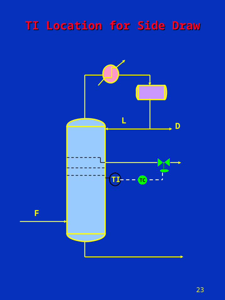
Optimum TI Location for Columns with Optimum TI Location for Columns with Side DrawsSide Draws
• Locate the TI in the vapor space one – two stages below the product draw for product EP control – This temperature (P-compensated)
correlates well with the product EP– Example
• Atmos column diesel 95% pt control
23
DL
F
TI
TI Location for Side DrawTI Location for Side Draw
TC
24
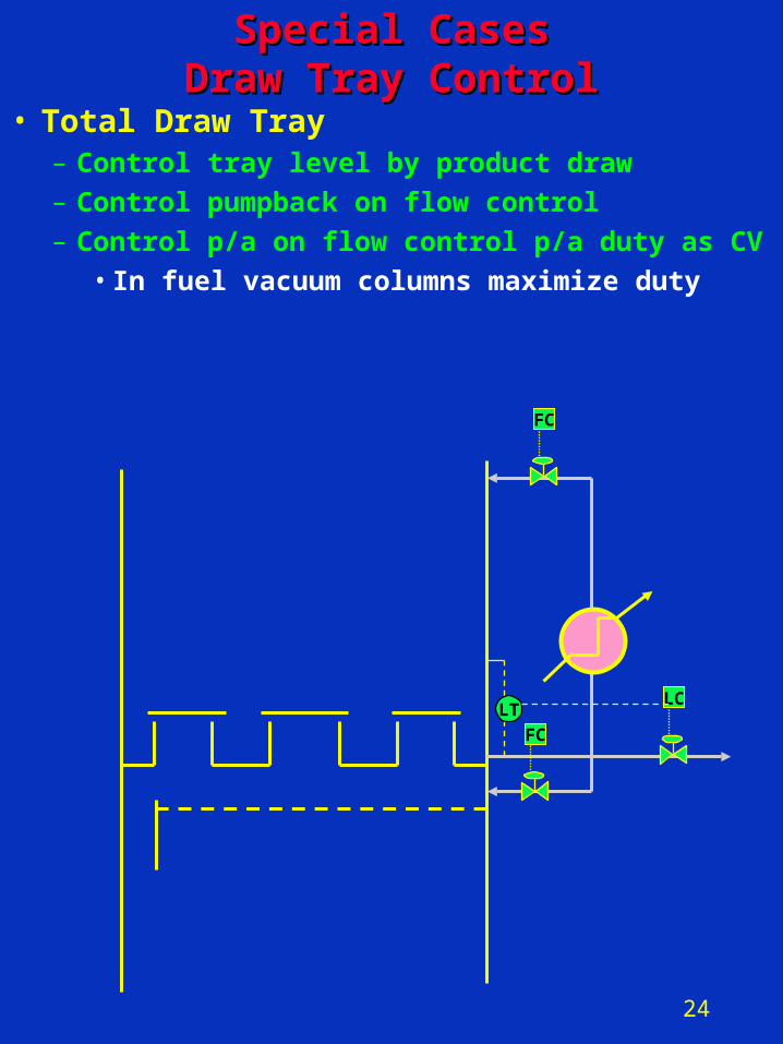
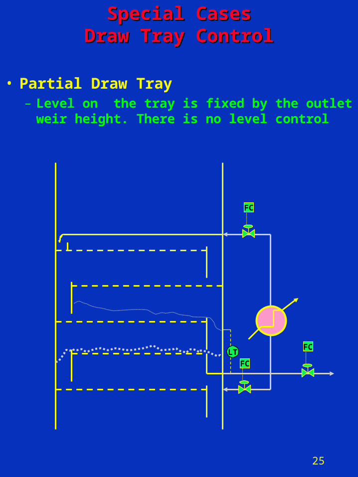
Special CasesSpecial CasesDraw Tray ControlDraw Tray Control
• Total Draw Tray– Control tray level by product draw– Control pumpback on flow control– Control p/a on flow control p/a duty as CV
• In fuel vacuum columns maximize duty
LC
FC
LT
FC
25
• Partial Draw Tray– Level on the tray is fixed by the outlet
weir height. There is no level control
FC
FC
LT
FC
Special CasesSpecial CasesDraw Tray ControlDraw Tray Control
26
Special CasesSpecial CasesStripping Steam FlowStripping Steam Flow
• Bottom stripping steam– Maximize to 8 – 12 lb stm per bbl of
product– Fixed flow control
• Side stripping steam– Minimize to meat front end spec– Use steam/ product ratio control
27
Distillation ControlDistillation Control
Case Study:Case Study:Deisobutanizer Control Deisobutanizer Control
Joyce KaumeyerSr. Consulting EngineerSr. Consulting Engineer
Prakash KarpeControl & Elec. Eng. Supt.Control & Elec. Eng. Supt.
ConocoPhillipsConocoPhillipsSan Francisco Refinery, RodeoSan Francisco Refinery, Rodeo
28
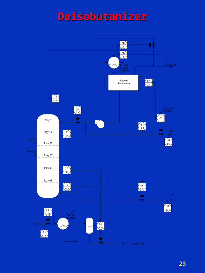
DeisobutanizerDeisobutanizer
Fuel Gas
IC4Tray 13
PIC
PIC
FIIC4
FICRFLX
TI
OVHD
TI
13
A
B
SW
LIC
IC4
SS
AI
IC4
Low LevelOverride
Tray 1
Tray 45 TIC
45
LIC
COND
PartiallyFlooded
Condenser
Steam
PIC
STM
Condensate
FI
STM
PartiallyFloodedReboiler
FloodedAccumulator
AI
NC4
NC4
LIC
NC4
FIC
NC4
Tray 25
Tray 37
Tray 60
Feed 1
Feed 2
29
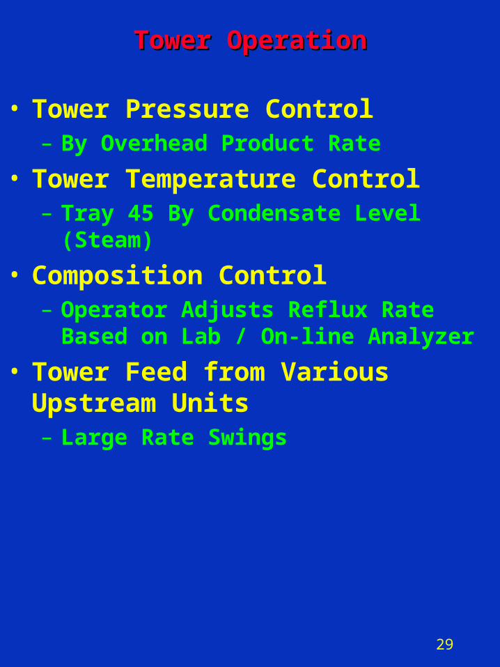
Tower OperationTower Operation
• Tower Pressure Control– By Overhead Product Rate
• Tower Temperature Control– Tray 45 By Condensate Level (Steam)
• Composition Control– Operator Adjusts Reflux Rate Based on
Lab / On-line Analyzer
• Tower Feed from Various Upstream Units – Large Rate Swings
30
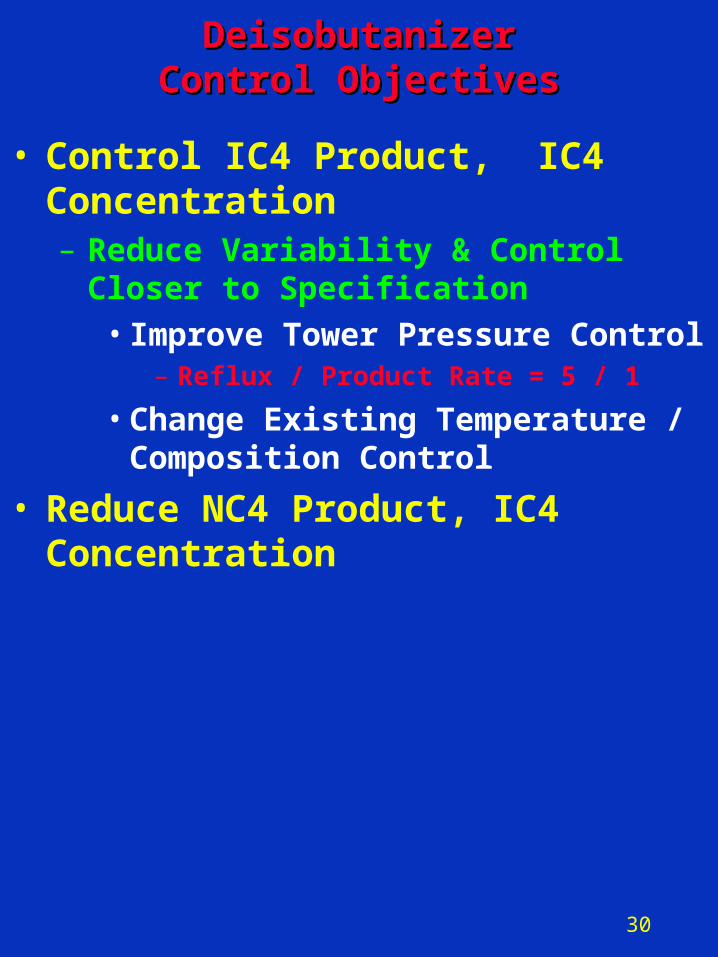
DeisobutanizerDeisobutanizerControl ObjectivesControl Objectives
• Control IC4 Product, IC4 Concentration – Reduce Variability & Control Closer to
Specification• Improve Tower Pressure Control
– Reflux / Product Rate = 5 / 1
• Change Existing Temperature / Composition Control
• Reduce NC4 Product, IC4 Concentration
31
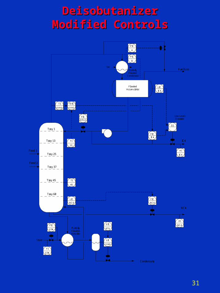
DeisobutanizerDeisobutanizerModified ControlsModified Controls
Fuel Gas
IC4Tray 13
PIC
PIC
FICIC4
FICRFLX
TI
OVHD
TI
13
A
B
SW
LIC
IC4
SS
AI
IC4
Low LevelOverride
Tray 1
Tray 45 TI
45
LIC
COND
PartiallyFlooded
Condenser
Steam
PIC
STM
Condensate
FI
STM
PartiallyFloodedReboiler
FloodedAccumulator
AI
NC4
NC4
LIC
NC4
FIC
NC4
TDIC
OVHD
UIC
BTU
Tray 25
Tray 37
Tray 60
Feed 1
Feed 2
32
90.0
92.0
94.0
96.0
98.0
100.0
%
Analyzer IC4 DT Predicted IC4
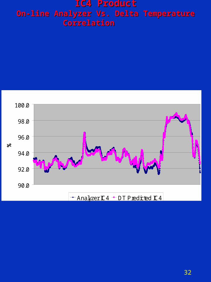
IC4 ProductIC4 ProductOn-line Analyzer Vs. Delta Temperature CorrelationOn-line Analyzer Vs. Delta Temperature Correlation
33
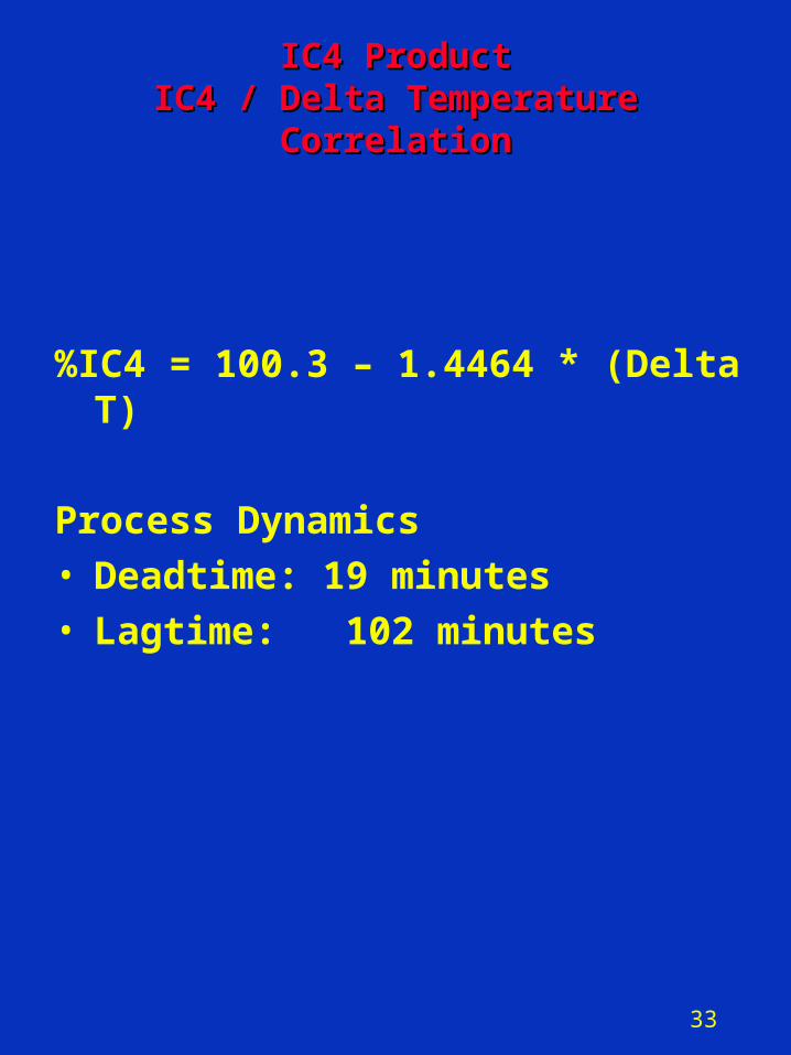
IC4 ProductIC4 ProductIC4 / Delta TemperatureIC4 / Delta Temperature
CorrelationCorrelation
%IC4 = 100.3 – 1.4464 * (Delta T)
Process Dynamics
• Deadtime: 19 minutes
• Lagtime: 102 minutes
34
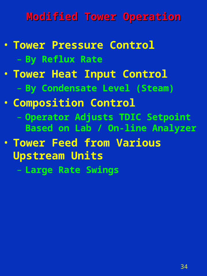
Modified Tower OperationModified Tower Operation
• Tower Pressure Control– By Reflux Rate
• Tower Heat Input Control– By Condensate Level (Steam)
• Composition Control– Operator Adjusts TDIC Setpoint Based
on Lab / On-line Analyzer
• Tower Feed from Various Upstream Units – Large Rate Swings
35
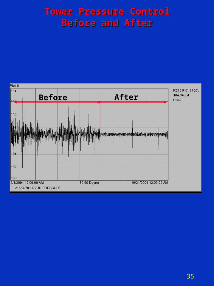
Tower Pressure ControlTower Pressure ControlBefore and AfterBefore and After
Before After
36
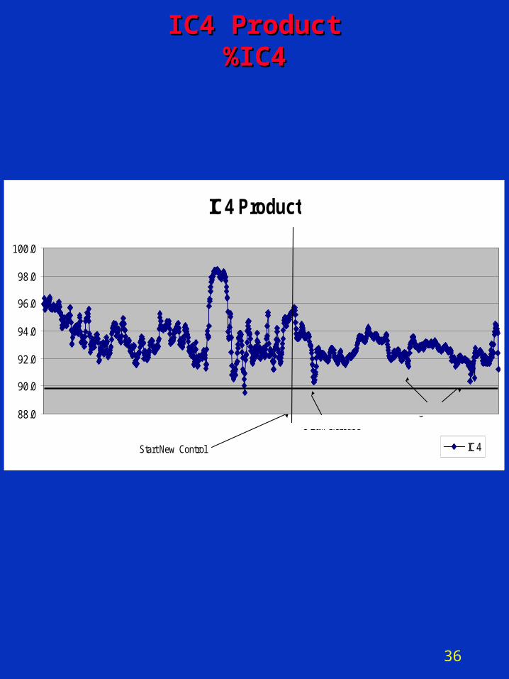
IC4 ProductIC4 Product%IC4%IC4
IC4 Product
88.0
90.0
92.0
94.0
96.0
98.0
100.0
IC4Start New Control
Steam Increase
High Pentanes
37
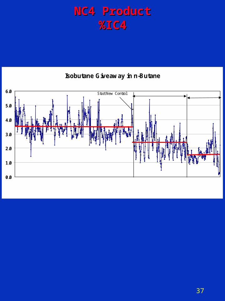
NC4 ProductNC4 Product%IC4%IC4
Isobutane Giveaway in n-Butane
0.0
1.0
2.0
3.0
4.0
5.0
6.0 Start New Control Operator TrainingInitial Implementation phase%
38
FutureFuture
• ARC – Add AIC Cascaded to TDIC
• Requires improved analyzer performance
– Add Heat Input Feed-Forward to AIC
-OR-• DMC
– Requires improved analyzer performance
– Hold for DCS platform conversion to Refinery Standard