Embed Size (px)
Citation preview
Chapter Outline Introduction Induced voltage Electromagnetic force, f Simple loop generator The voltage induced in a rotating loop The induced torque in the rotating loop Practical generator Armature winding Problems with commutation in real machines Solutions to the problems with commutation The internal generated voltage and induced torque equations of real dc machines Power flow and losses in dc machines
Electrical Machines Getu.G:[email protected]
IntroductionElectric machines convert electrical energy(power) to
mechanical energy(power) or vice versa. This process of conversion is known as
electromechanical energy conversion. An electric machine is therefore a link between an
electrical system and a mechanical system. In these machines the conversion is reversible. If the conversion is from mechanical to electrical
energy, the machine is said to act as a generator. If the conversion is from electrical to mechanical
energy, the machine is said to act as a motor.Electrical Machines Getu.G:[email protected]
3
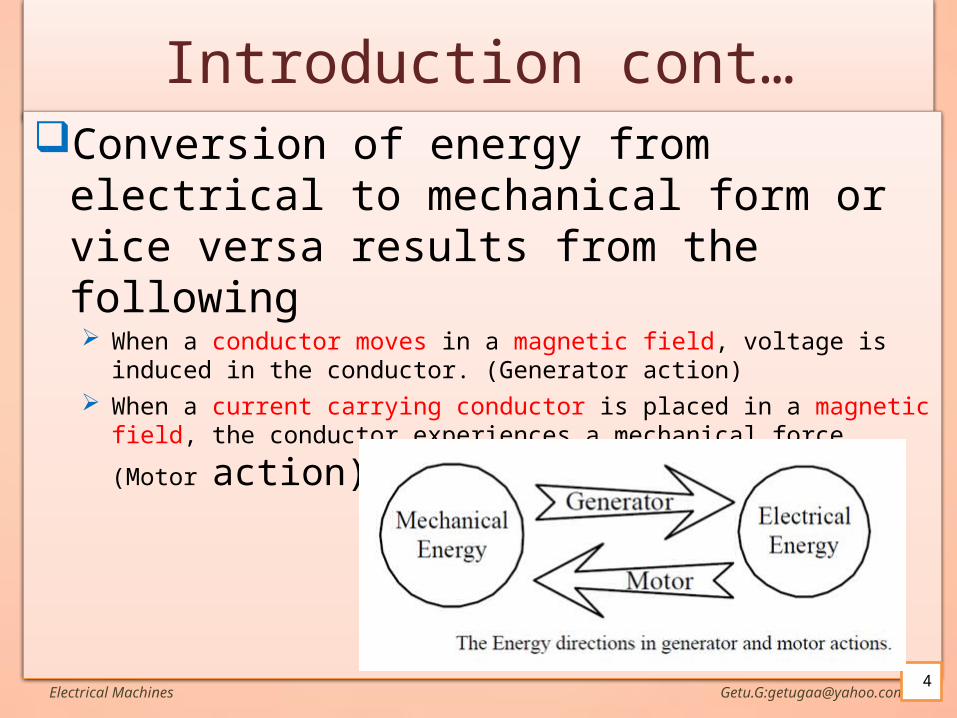
Introduction cont…Conversion of energy from electrical to
mechanical form or vice versa results from the following When a conductor moves in a magnetic field, voltage is induced in the conductor.
(Generator action) When a current carrying conductor is placed in a magnetic field, the conductor
experiences a mechanical force. (Motor action)
Electrical Machines Getu.G:[email protected]
Introduction cont…These two effects occur simultaneously whenever energy
conversion takes place from electrical to mechanical or vice versa.
In motoring action the electrical system makes current flow through conductors
that are placed in the magnetic field. A force is produced on each conductor. If the conductors are placed on a structure free to rotate,
an electromagnetic torque will be produced, tending to make the rotating structure rotate at some speed.
If the conductors rotate in a magnetic field, a voltage will also be induced in each conductor.
Electrical Machines Getu.G:[email protected]
Introduction cont… In generating action,
the process is reversed. The rotating structure, the rotor, is driven by a prime mover (such as a
steam turbine or a diesel engine). A voltage will be induced in the conductors that are rotating with the
rotor. If an electrical load is connected to the winding formed by these
conductors, a current i will flow, delivering electrical power to the load.
Moreover, the current flowing through the conductor will interact with the magnetic field to produce a reaction torque, which will tend to oppose the torque applied by the prime mover.
Note: In both motor and generator actions, the coupling magnetic field is involved in producing a torque and an induced voltage.
Electrical Machines Getu.G:[email protected]
Introduction cont…DC machines are generators that convert mechanical
energy to DC electric energy and motors that convert DC electric energy to mechanical energy.
Most DC machines are like AC machines in that they have AC voltages and currents within them
DC machines have a DC output only because a mechanism exists that converts the internal ac voltages to dc voltages at their terminals. Since this mechanism is called a commutator, dc machinery is also known as commutating machinery.
Electrical Machines Getu.G:[email protected]
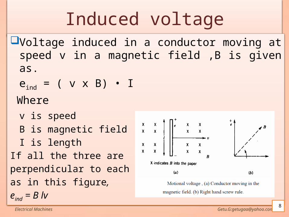
Induced voltageVoltage induced in a conductor moving at speed v in
a magnetic field ,B is given as.
eind = ( v x B) • I
Where
v is speed
B is magnetic field
I is length
If all the three are
perpendicular to each other
as in this figure,
eind = B lvElectrical Machines Getu.G:[email protected]
8
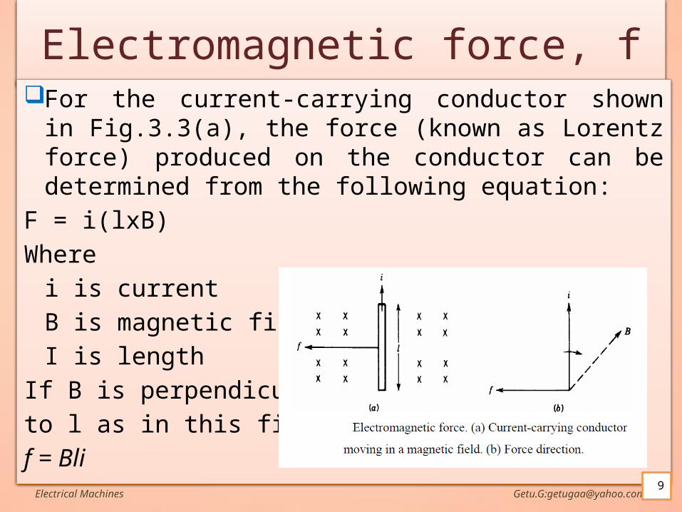
Electromagnetic force, fFor the current-carrying conductor shown in Fig.3.3(a),
the force (known as Lorentz force) produced on the conductor can be determined from the following equation:
F = i(lxB)
Where
i is current
B is magnetic field
I is length
If B is perpendicular
to l as in this figure,
f = BliElectrical Machines Getu.G:[email protected]
9
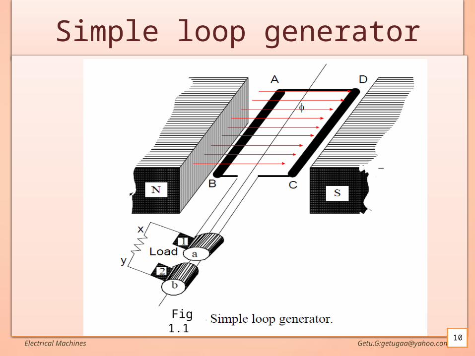
Simple loop generatorIn the figure (fig 1.1 and 1.2)is shown a single turn
rectangular copper coil ABCD moving about its own axis, a magnetic field provided by either permanent magnets or electromagnets.
The two ends of the coil are joined to two slip-rings or discs a and b which are insulated from each other and from the central shaft.
Two collecting brushes (of carbon or copper) (1 and 2)press against the slip rings.
Their function is to collect the current induced in the coil and to convey it to the external load resistance R.
Electrical Machines Getu.G:[email protected]
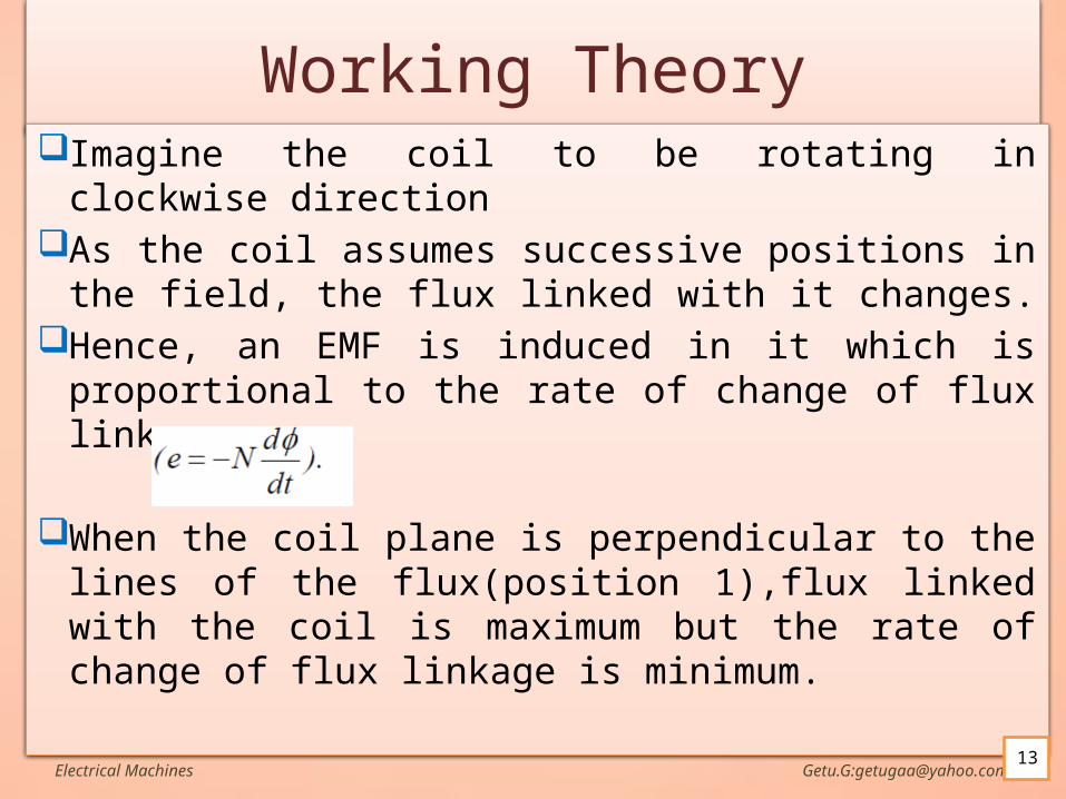
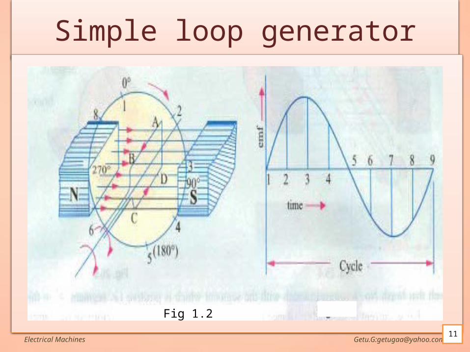
Working TheoryImagine the coil to be rotating in clockwise
direction As the coil assumes successive positions in the
field, the flux linked with it changes. Hence, an EMF is induced in it which is
proportional to the rate of change of flux linkages.
When the coil plane is perpendicular to the lines of the flux(position 1),flux linked with the coil is maximum but the rate of change of flux linkage is minimum.
Electrical Machines Getu.G:[email protected]
Working Theory cont..Fig 1.2At this position 1,
the coil sides AB and CD run parallel to the line of the flux(slide along).
The induces emf=NdΦ/dt=0Take this as start position(angle of rotation θ=00)
Electrical Machines Getu.G:[email protected]
Working Theory cont..Until position 3,dΦ/dt increases.At position 3:
Θ=900The coil is horizontal(parallel to flux lines)AB and CD run perpendicular to the line of the fluxThe flux linked with the coil is minimumBut rate of change of flux linkage is maximumSo,maximum emf is induced
Electrical Machines Getu.G:[email protected]
Working Theory cont..From 900 to 1800,the flux linked with the loop
gradually increases but dΦ/dt decreasesSo the emf decreases gradually and is zero at
position 5(1800).During this half cycle,
The emf is from A to B and C to D.Direction of current ABMLCDCurrent through R is M to LHalf revolution of the coil completes
Electrical Machines Getu.G:[email protected]
Working Theory cont..In the next half revolution(i,e 1800 to 3600)
The variations in emf are similar to those in first halfMaximum in position 7Minimum in position 1But the direction of induced current is reversed (D to
C and B to A)Path of current DCLMBA (reversed)The current through R is L to M(reversed)i.e The current through R is AC
Electrical Machines Getu.G:[email protected]
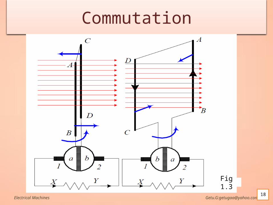
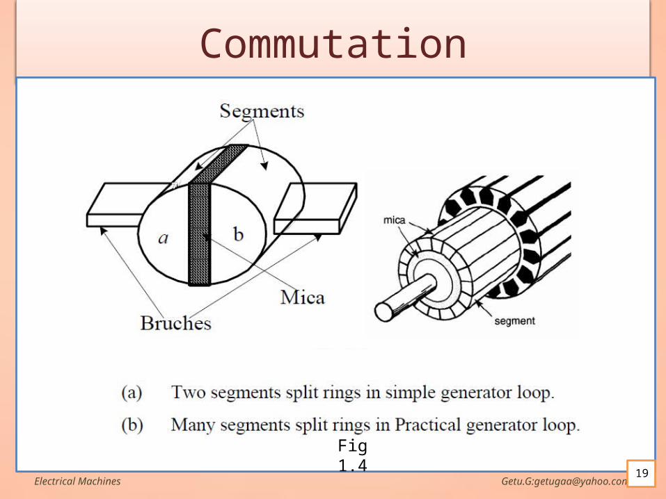
CommutationFor making the flow of current unidirectional in the
external circuit, the slip rings are replaced by split rings which shown in Fig 1.3 and 1.4.
The split rings are made out of a conducting cylinder which is cut into two halves or segments insulated from each other by a thin sheet of mica or some other insulating material.
As before, the coil ends are joined to these segments on which rest the carbon or copper brushes.
In the practical generator which has more than two poles and more than one coil the split rings has not just two halves but has many parts as shown in Fig1.4 (b).
Electrical Machines Getu.G:[email protected]
CommutationIt is seen (Fig13.(a) to Fig1.3 (b)) that in the first
half revolution current flows along ABXYCD i.e. the brush No. 1 in contact with segment a acts as the positive end of the supply and b as the negative end.
Electrical Machines Getu.G:[email protected]
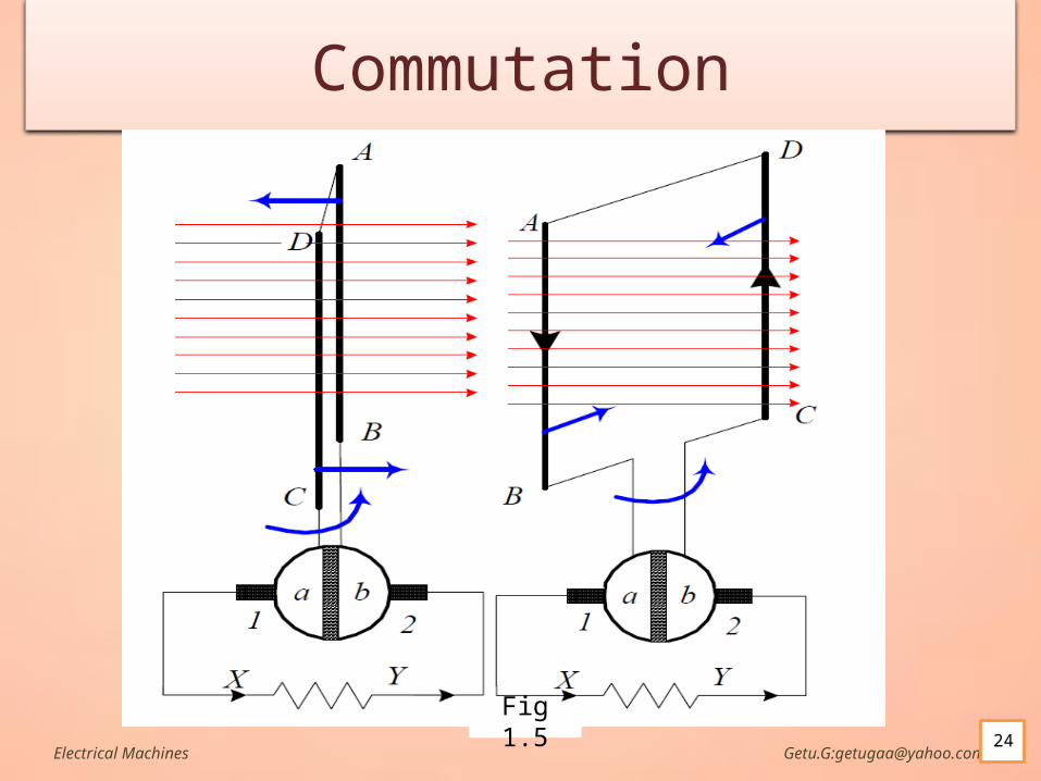
CommutationIn the next half revolution (fig 1.5), the direction
of the induced current in the coil has reversed. But at the same time, the positions of segments a
and b have also reversed with the result that brush No. 1 comes in touch with that segment which is positive i.e segment b in this case.
Hence, the current in the load resistance again flows from X to Y.
Electrical Machines Getu.G:[email protected]
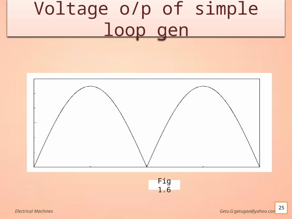
CommutationThe waveform of the current through the external
circuit is as shown in Fig1.6. This current is unidirectional but not continuous
like pure direct current.It should be noted that the position of brushes is so
arranged that the changeover of segments a and b from one brush to the other takes place when the plane of the rotating coil is at right angles to the plane of the flux lines.
It is so because in that position, the induced EMF in the coil is zero.
Electrical Machines Getu.G:[email protected]
The voltage induced in a rotating loop
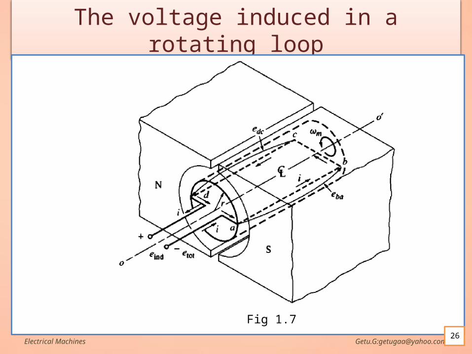
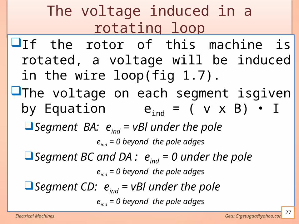
If the rotor of this machine is rotated, a voltage will be induced in the wire loop(fig 1.7).
The voltage on each segment isgiven by Equation eind = ( v x B) • ISegment BA: eind = vBl under the pole
eind = 0 beyond the pole adges
Segment BC and DA : eind = 0 under the poleeind = 0 beyond the pole adges
Segment CD: eind = vBl under the poleeind = 0 beyond the pole adges
Electrical Machines Getu.G:[email protected]
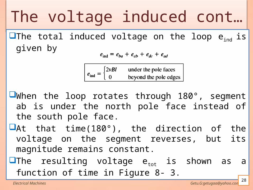
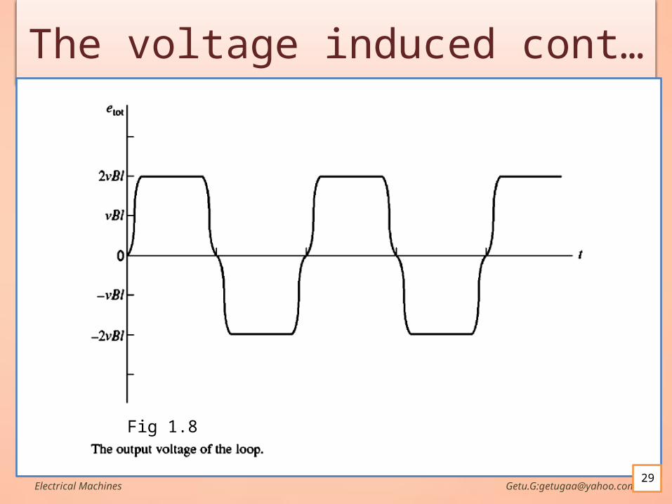
The voltage induced cont…The total induced voltage on the loop eind is given by
When the loop rotates through 180°, segment ab is under the north pole face instead of the south pole face.
At that time(180°), the direction of the voltage on the segment reverses, but its magnitude remains constant.
The resulting voltage etot is shown as a function of time in Figure 8- 3.
Electrical Machines Getu.G:[email protected]

The voltage induced cont…Notice that the tangential velocity v of the edges
of the loop can be expressed as v = rωwhere r is the radius from axis of rotation out to the
edge of the loop and w is the angular velocity of the loop.
Electrical Machines Getu.G:[email protected]
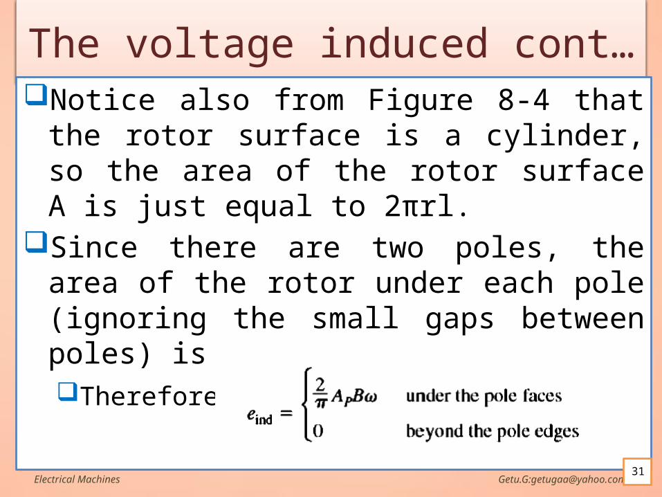
The voltage induced cont…Notice also from Figure 8-4 that the rotor surface
is a cylinder, so the area of the rotor surface A is just equal to 2πrl.
Since there are two poles, the area of the rotor under each pole (ignoring the small gaps between poles) is Ap = πrl.Therefore,
Electrical Machines Getu.G:[email protected]
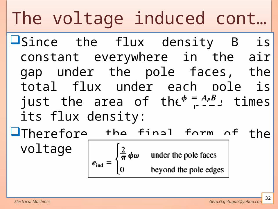
The voltage induced cont…Since the flux density B is constant everywhere in
the air gap under the pole faces, the total flux under each pole is just the area of the pole times its flux density:
Therefore, the final form of the voltage equation is
Electrical Machines Getu.G:[email protected]
The voltage induced cont…Thus, the voltage generated in the machine is
equal to the product of the flux inside the machine and the speed of rotation of the machine, multiplied by a constant representing the mechanical construction of the machine.
In general, the voltage in any real machine will depend on the same three factors:
1. The flux in the machine
2. The speed of rotation
3. A constant representing the construction of the machine
Electrical Machines Getu.G:[email protected]
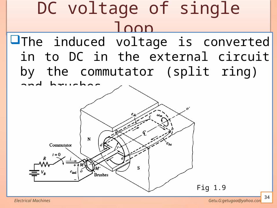
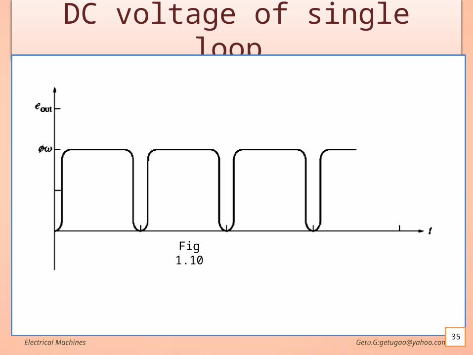
DC voltage of single loop…The induced voltage is converted in to DC in the
external circuit by the commutator (split ring) and brushes
Electrical Machines Getu.G:[email protected]
Fig 1.9
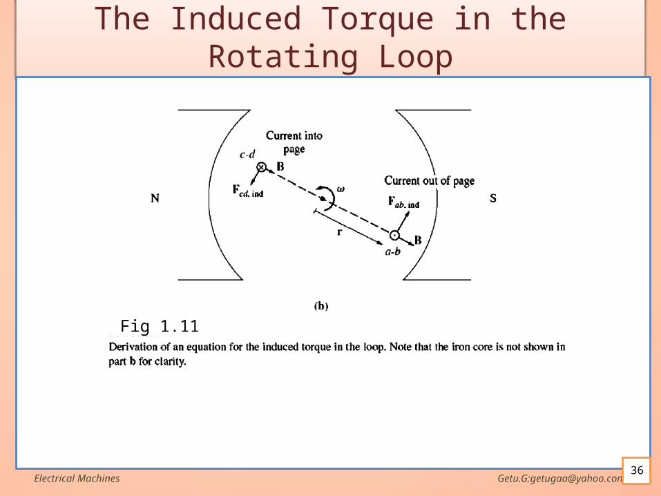
The Induced Torque in the Rotating Loop
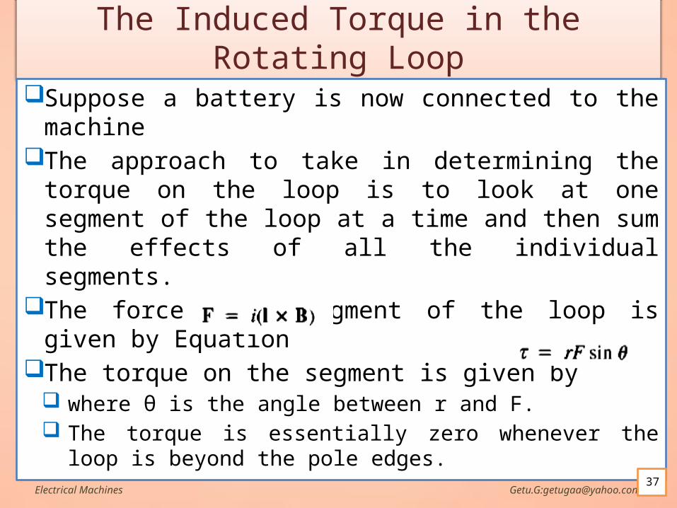
Suppose a battery is now connected to the machineThe approach to take in determining the torque on
the loop is to look at one segment of the loop at a time and then sum the effects of all the individual segments.
The force on a segment of the loop is given by Equation
The torque on the segment is given bywhere θ is the angle between r and F. The torque is essentially zero whenever the loop is
beyond the pole edges.Electrical Machines Getu.G:[email protected]
37
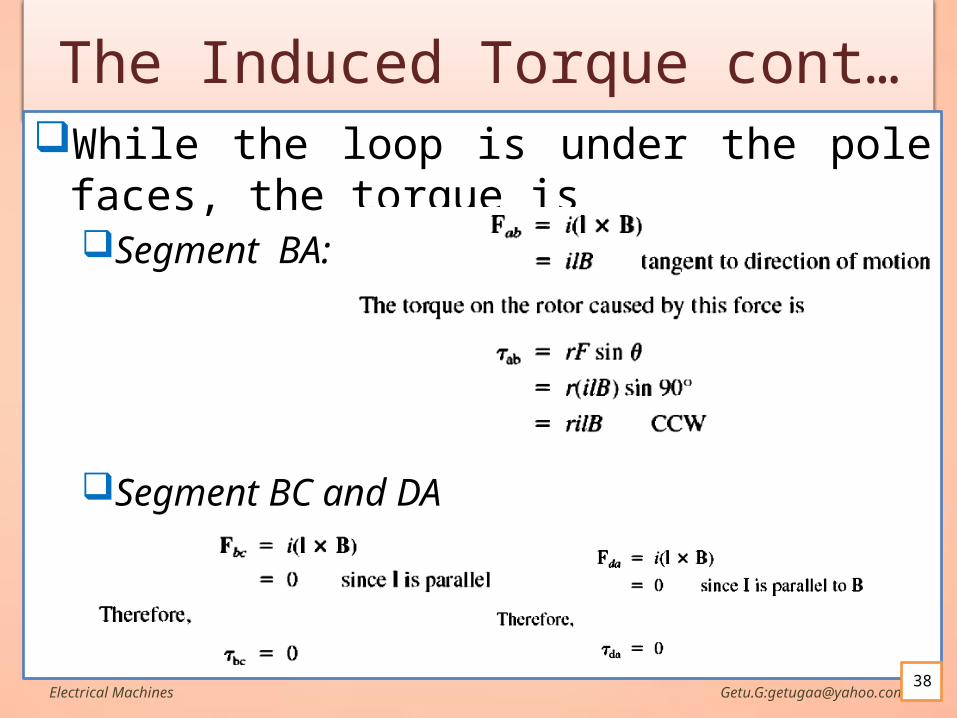
The Induced Torque cont…While the loop is under the pole faces, the torque
isSegment BA:
Segment BC and DA
Electrical Machines Getu.G:[email protected]
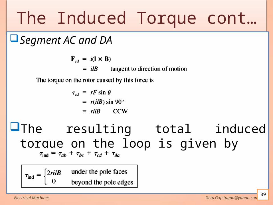
The Induced Torque cont…Segment AC and DA
The resulting total induced torque on the loop is given by
Electrical Machines Getu.G:[email protected]
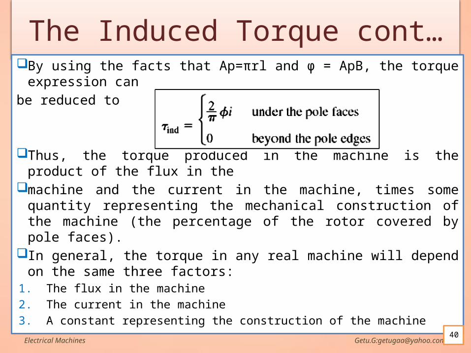
The Induced Torque cont… By using the facts that Ap=πrl and ϕ = ApB, the torque expression can
be reduced to
Thus, the torque produced in the machine is the product of the flux in the
machine and the current in the machine, times some quantity representing the mechanical construction of the machine (the percentage of the rotor covered by pole faces).
In general, the torque in any real machine will depend on the same three factors:
1. The flux in the machine
2. The current in the machine
3. A constant representing the construction of the machine
Electrical Machines Getu.G:[email protected]
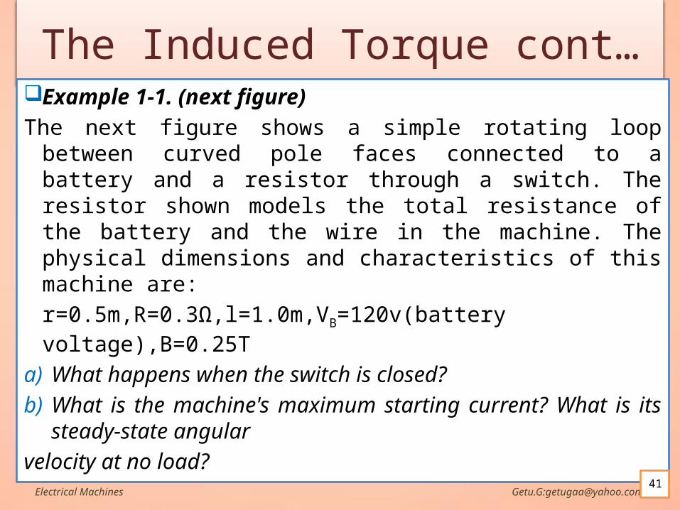
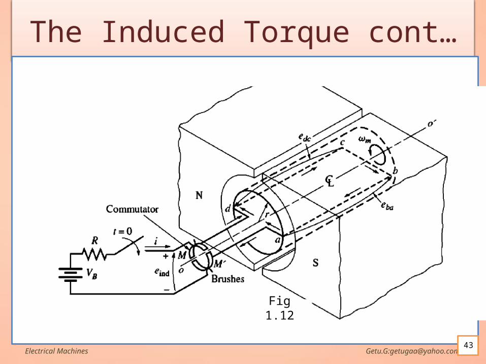
The Induced Torque cont…Example 1-1. (next figure)
The next figure shows a simple rotating loop between curved pole faces connected to a battery and a resistor through a switch. The resistor shown models the total resistance of the battery and the wire in the machine. The physical dimensions and characteristics of this machine are:
r=0.5m,R=0.3Ω,l=1.0m,VB=120v(battery voltage),B=0.25T
a) What happens when the switch is closed?
b) What is the machine's maximum starting current? What is its steady-state angular
velocity at no load?Electrical Machines Getu.G:[email protected]
41
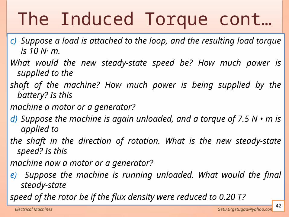
The Induced Torque cont…c) Suppose a load is attached to the loop, and the resulting load torque is
10 N· m.
What would the new steady-state speed be? How much power is supplied to the
shaft of the machine? How much power is being supplied by the battery? Is this
machine a motor or a generator?
d) Suppose the machine is again unloaded, and a torque of 7.5 N • m is applied to
the shaft in the direction of rotation. What is the new steady-state speed? Is this
machine now a motor or a generator?
e) Suppose the machine is running unloaded. What would the final steady-state
speed of the rotor be if the flux density were reduced to 0.20 T?Electrical Machines Getu.G:[email protected]
42
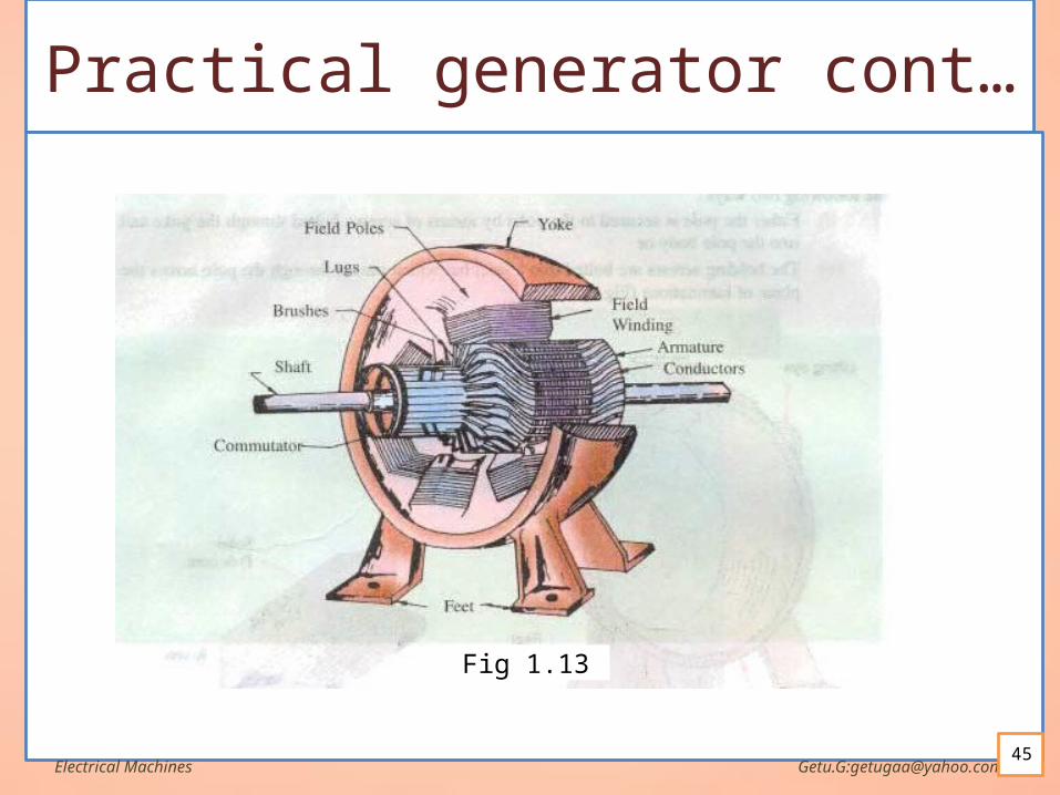
Practical generator The simple loop generator has been considered in detail merely to
bring out the basic principle underlying the construction and working of as actual generator illustrated in Fig.3.13 which consists of the following essential parts:
i. Magnetic Frame or Yoke
ii. Pole-cores and Pole-shoes
iii. Pole Coils or Field Coils
iv. Armature Core
v. Armature Windings or
vi. Commutator
vii. Brushes and Bearings
Of these, the yoke, the pole cores, the armature core and air gaps between the poles and the armature core form the magnetic circuit whereas the rest form the electrical circuit.Electrical Machines Getu.G:[email protected]
44
Practical generator cont…
i. YokeThe outer frame or yoke serves Provides mechanical support for the poles and acts as a
protecting cover for the whole machine Caries the magnetic flux produced by poles
ii. Pole cores and pole shoes The field magnets consist of pole cores and pole shoes. The pole shoes serve two purposes
1. Spread out the flux in the air gap and being of larger crossection ,reduce the reluctance of the magnetic path
2. Support field coils
They are made of lamminated steelElectrical Machines Getu.G:[email protected]
46
Practical generator cont…
iii. Pole coils or field coils Consist of copper wires are former wound for correct
dimension The former is removed and the wound coil is put in
to place over the core When current passes through these coils,
electromagnetic poles formed to produce flux to be cut by the armature conductors
Electrical Machines Getu.G:[email protected]
Practical generator cont…
iv. Armature core Houses armature conductors(coils) and cause them to
rotate and hence cut the magnetic flux produced by the poles.
Slots to place armature coils Lamminated steel discs(to reduce eddy current loss)
and perforated (for cooling)
Electrical Machines Getu.G:[email protected]
Practical generator cont…
v. Armature windings Usually former wound Then put in the armature slots lined with tough
insulating material The conductors of the coil insulated from each other
Electrical Machines Getu.G:[email protected]
Practical generator cont…
vi. Commutator The function of the commutator is to facilitate
collection of current from the armature conductors i.e. converts the alternating current induced in the armature conductors into unidirectional current in the external load circuit.
It is of cylindrical structure and is built up of wedge-shaped segments of high conductivity hard-drawn or drop-forged
Electrical Machines Getu.G:[email protected]
Practical generator cont…
vii. Brushes and bearings Brush:
Function to collect current from commutator Made of carbon or graphite In the shape of rectangular box Adjustable spring tension to press it against the commutator Flexible copper at the top to carry current from brushes to
holder Number of brushes per spindle is according to amount of
current to be collected
Bearing To couple the moving part(armature) and stationary
part(stator)Electrical Machines Getu.G:[email protected]
51
Armature winding Two types of windings mostly employed for the
armatures of DC machines are known as Lap Winding and Wave Winding.
The difference between the two is merely due to the different arrangement of the end connections at the front or commutator end of armature.
The coils of rotor part or armature are arranged in many options which influence the performance of DC machines.
Electrical Machines Getu.G:[email protected]
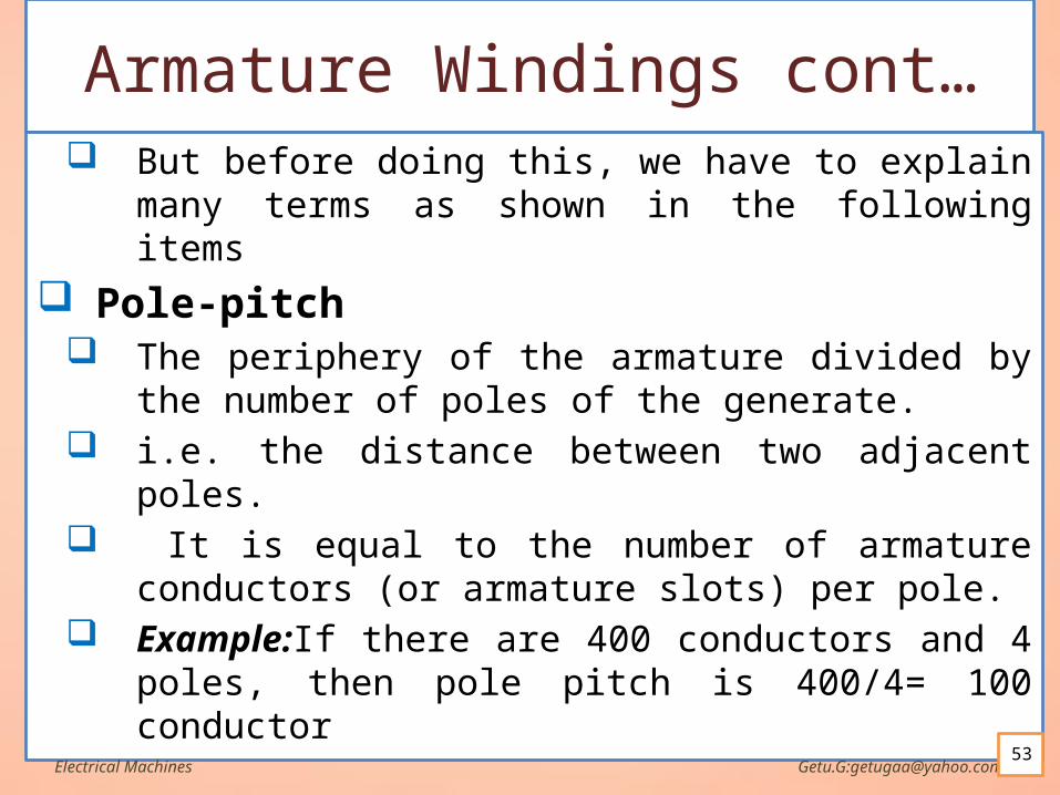
Armature Windings cont… But before doing this, we have to explain many
terms as shown in the following items
Pole-pitch The periphery of the armature divided by the number
of poles of the generate. i.e. the distance between two adjacent poles. It is equal to the number of armature conductors (or
armature slots) per pole. Example:If there are 400 conductors and 4 poles,
then pole pitch is 400/4= 100 conductor
Electrical Machines Getu.G:[email protected]
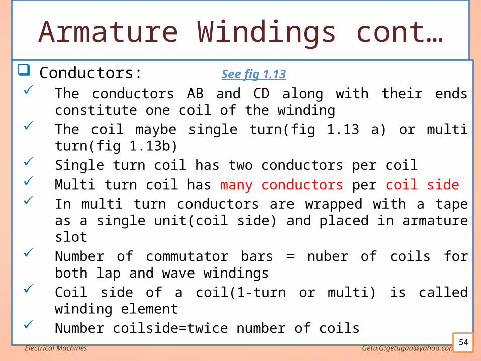
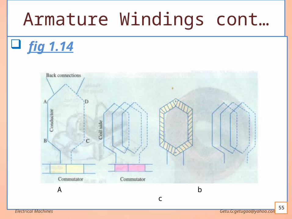
Armature Windings cont… Conductors:
The conductors AB and CD along with their ends constitute one coil of the winding
The coil maybe single turn(fig 1.13 a) or multi turn(fig 1.13b) Single turn coil has two conductors per coil Multi turn coil has many conductors per coil side In multi turn conductors are wrapped with a tape as a single
unit(coil side) and placed in armature slot Number of commutator bars = nuber of coils for both lap and
wave windings Coil side of a coil(1-turn or multi) is called winding element Number coilside=twice number of coils
Electrical Machines Getu.G:[email protected]
See fig 1.13
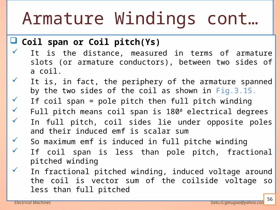
Armature Windings cont… Coil span or Coil pitch(Ys)
It is the distance, measured in terms of armature slots (or armature conductors), between two sides of a coil.
It is, in fact, the periphery of the armature spanned by the two sides of the coil as shown in Fig.3.15.
If coil span = pole pitch then full pitch winding Full pitch means coil span is 1800 electrical degrees In full pitch, coil sides lie under opposite poles and their
induced emf is scalar sum So maximum emf is induced in full pitche winding If coil span is less than pole pitch, fractional pitched winding In fractional pitched winding, induced voltage around the coil
is vector sum of the coilside voltage so less than full pitched Electrical Machines Getu.G:[email protected]
56
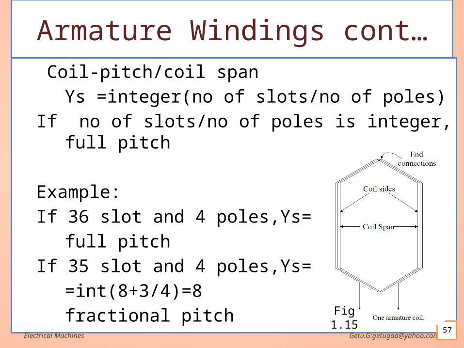
Armature Windings cont… Coil-pitch/coil span
Ys =integer(no of slots/no of poles)
If no of slots/no of poles is integer, full pitch
Example:
If 36 slot and 4 poles,Ys=36/4=9
full pitch
If 35 slot and 4 poles,Ys=int(35/4)
=int(8+3/4)=8
fractional pitch
Electrical Machines Getu.G:[email protected]
Fig 1.15
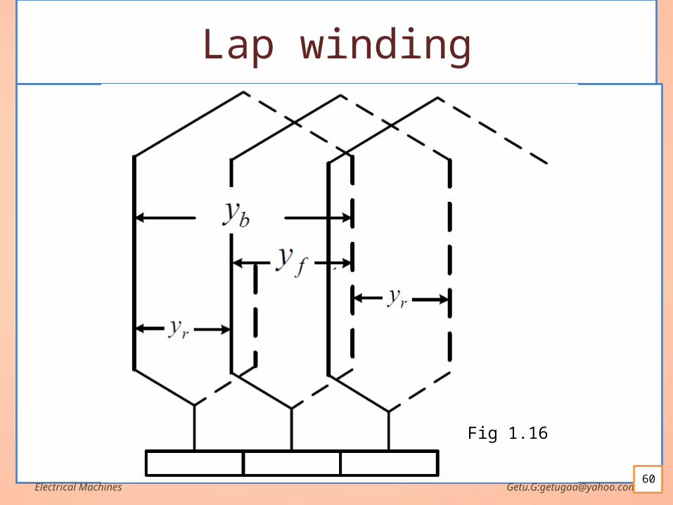
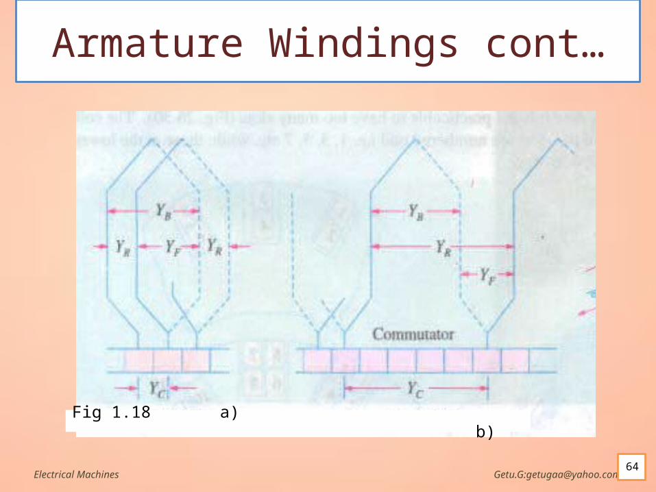
Armature Windings cont… Back Pitch
The distance, measured in terms of the armature conductors(slots) which a coil advances on the back of the armature is called back pitch and is denoted by Yb.
In other words, it is the number difference of the conductors connected together at the back end of the armature.
Electrical Machines Getu.G:[email protected]
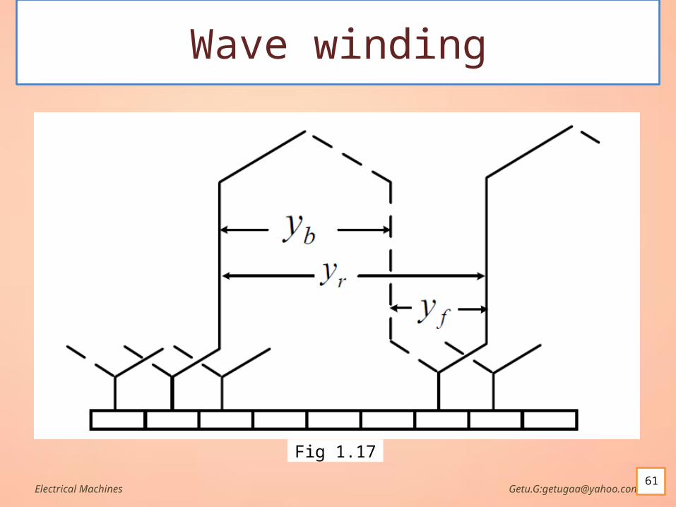
Armature Windings cont… Front Pitch
The number of armature conductors or elements spanned by a coil on the front (or commutator end of an armature) is called the front pitch and is designated by Yf.
Alternatively, the front pitch may be defined as the distance (in terms of armature conductors) between the second conductor of one coil and the first conductor of the next coil which are connected together to commutator end of the armature.
Both front and back pitches for lap and wave-winding are shown in Fig. 3.16 and Fig.3.17 respectively
Electrical Machines Getu.G:[email protected]
Armature Windings cont… Resultant Pitch
It is the distance between the beginning of one coil and the beginning of the next coil to which it is connected as shown in Fig.3.16 and Fig.3.17.
As a matter of precaution, it should be kept in mind that all these pitches, though normally stated in terms of armature conductors(coil sides), are also sometimes given in terms of armature slots or commutator bars.
Electrical Machines Getu.G:[email protected]
Armature Windings cont… Commutator Pitch (Yc)
It is the distance (measured in commutator bars or segments) between the segments to which the two ends of a coil are connected as shown in Fig.3.18.
Equal to number of bars b/n coil leads For lap winding, Yc = Yb - Yf and equal to its
‘plex’, For wave winding: Yc = Yb + Yf
Electrical Machines Getu.G:[email protected]
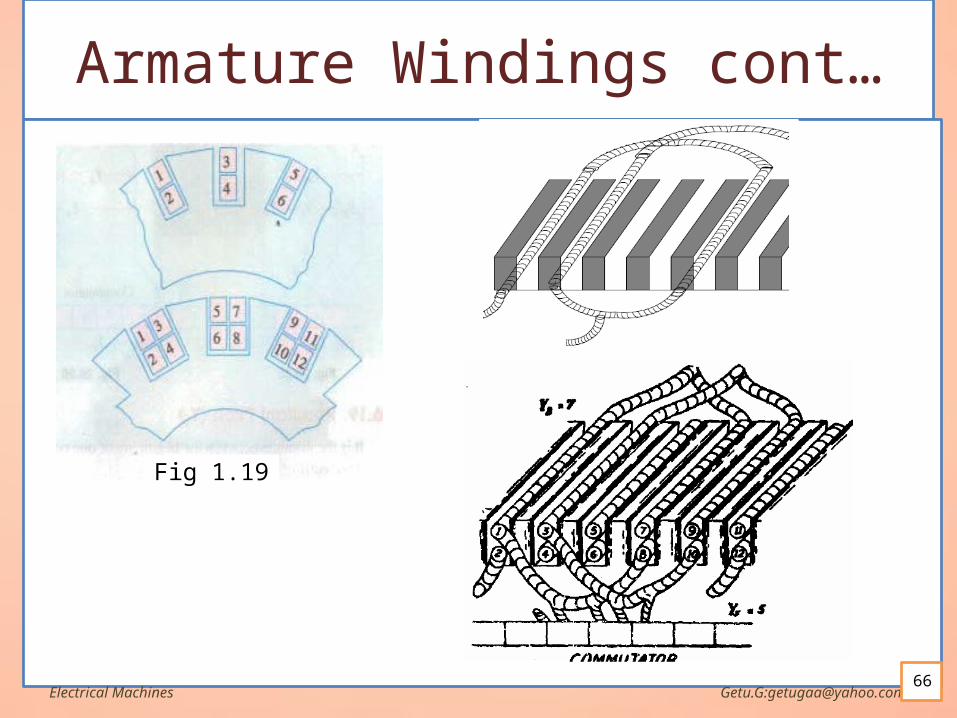
Armature Windings cont… Single-layer Winding
It is that winding in which one conductor or one coil side is placed in each armature slot as shown in Fig 1.19.
Such a winding is not much used. Two-Layer Winding
In this type of winding,' there are two conductors or coil sides-per slot arranged in two layers.
Usually, one side of every coil lies in the upper half of one slot and other side lies in the lower half of some other slot at a distance of approximately one pitch away (Fig 1.19).
The transfer of , the coil from one slot to another is usually made in a radial plane by means of a peculiar bend or twist at the back
Coil sides(slots) at upper side are numbered odd, but those in the lower are numbered even
Electrical Machines Getu.G:[email protected]
Armature Windings cont… Multiplex Winding
In such winding, several sets of complete closed and independent windings
Increases number of parallel paths in a winding Increases current rating
Electrical Machines Getu.G:[email protected]
Armature Windings cont… Lap and wave windings
The winding types of the armature of the DC machines can be divided to two main types, Lap and Wave windings.
The main difference between them is the method of connecting the terminals of coils to the commutator segments.
In case of lap wound there are two kinds, the simplex lap winding and multiple lap winding.
For simple lap winding the two terminals of one coil is connected to adjusent two commutator segments as shown in Fig 1.18.
Each of them can be arranged progressively or retrogressively
Electrical Machines Getu.G:[email protected]
Armature Windings cont… The following rules apply to both
Yf and Yb are approximately equal to pole pitch(to get full pitch)
Yf and Yb should be odd Number of commutator segment=no of slot=no of
coils=1/2 no of coil sides Winding must close up on itself
Electrical Machines Getu.G:[email protected]
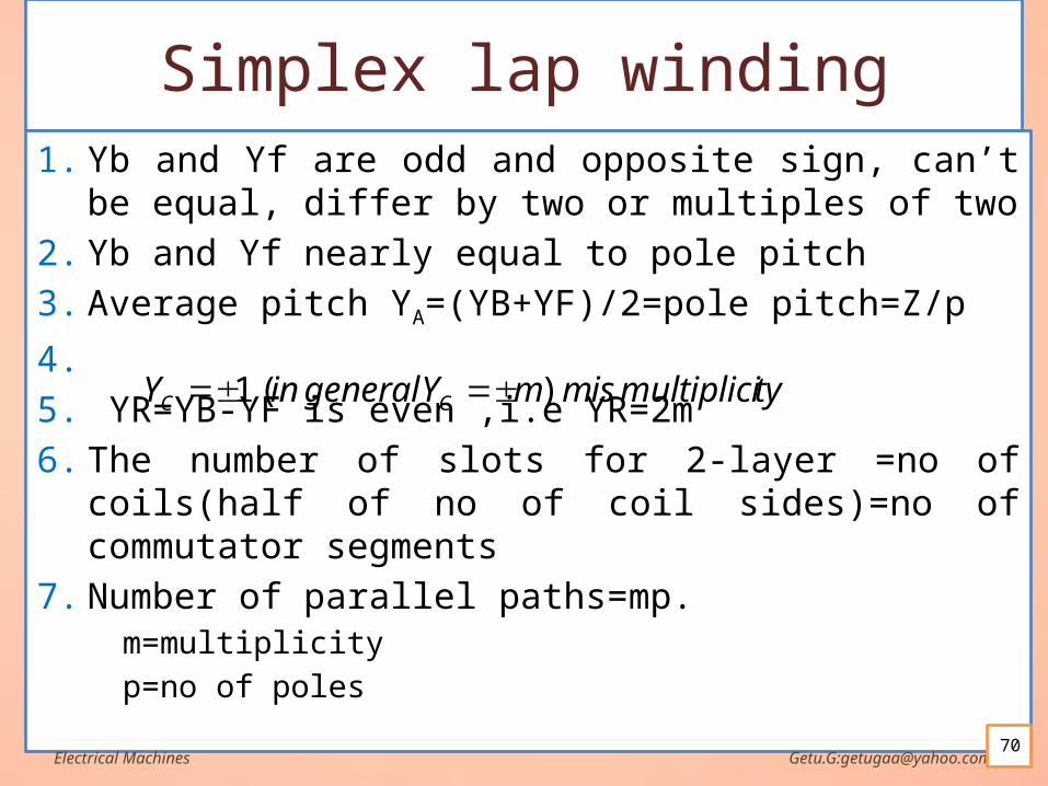
Simplex lap winding1. Yb and Yf are odd and opposite sign, can’t be equal,
differ by two or multiples of two
2. Yb and Yf nearly equal to pole pitch
3. Average pitch YA=(YB+YF)/2=pole pitch=Z/p
4.
5. YR=YB-YF is even ,i.e YR=2m
6. The number of slots for 2-layer =no of coils(half of no of coil sides)=no of commutator segments
7. Number of parallel paths=mp.m=multiplicity
p=no of polesElectrical Machines Getu.G:[email protected]
tymultipliciismmYgeneralinY CC )(1
Simplex lap winding
Electrical Machines Getu.G:[email protected]
.
.
.
)()(
)()1(1
1
1
1
1
544433
3222
CYCtoCCYCtoC
CYCtoCCYto
connectionFrontconnectionBack
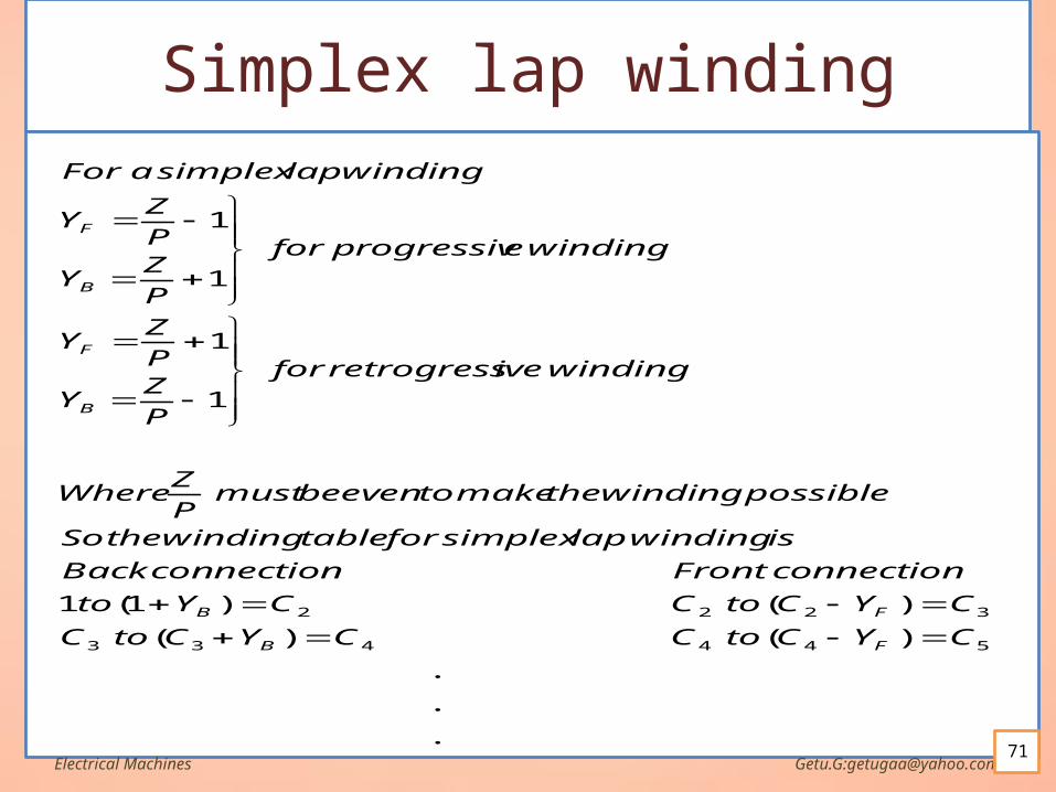
iswindinglapsimplexfortablewindingtheSo
possiblewindingthemaketoevenbemustP
ZWhere
windingiveretrogressfor
P
ZY
P
ZY
windingeprogressivfor
P
ZY
P
ZY
lapwindingsimplexaFor
FB
FB
B
F
B
F
Position and number of brushes It is very important that brushes are in correct position
relative to the field poles. By right-hand rule is used to identify the direction of e.m.f.
in each conductor A positive brush will be placed on that commutator segment
where the currents in the coils are meeting to flow out of the segment.
A negative brush will be placed on that commutator segment where the currents in the coils are meeting to flow in.
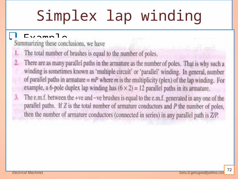
in a simplex lap winding, the number of brushes is equal to the number of poles.
Brushes of the same polarity are connected together,
Electrical Machines Getu.G:[email protected]
Position and number of brushes Therefore, in a simplex lap winding, the number
of parallel paths is equal to the number of poles.
Electrical Machines Getu.G:[email protected]
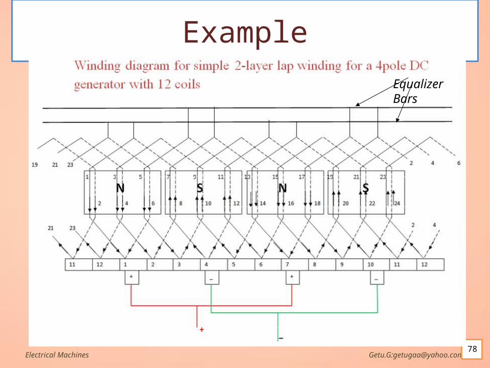
Equalizing Connections Because of wear in the bearings, and for other reasons, the air gaps in a
generator become unequal and, therefore, the flux in some poles becomes greater than in others.
This causes the voltages of the different parallel paths to be unequal and unequal additional circulating currents in the brush.
To relieve the brushes of these circulating currents, points on the armature that are at the same potential are connected together by means of copper bars called equalizer rings.
The equalizers provide a low resistance path for the circulating current. As a result, the circulating current due to the slight differences in the voltages of the various parallel paths passes through the equalizer rings instead of passing through the brushes.
Equalizer rings should be used only on windings in which the number of coils is a multiple of the number of poles.
Satisfactory results are obtained by connecting about every third coil to an equalizer ring.Electrical Machines Getu.G:[email protected]
75
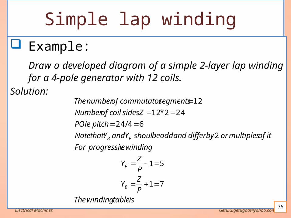
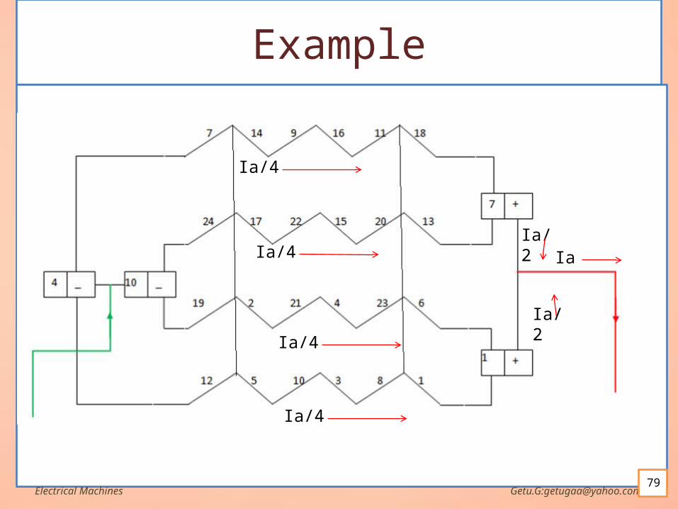
Simple lap winding Example:
Draw a developed diagram of a simple 2-layer lap winding for a 4-pole generator with 12 coils.
Solution:
Electrical Machines Getu.G:[email protected]
istablewindingTheP
ZY
P
ZY
windingeprogressivFor
itofmultiplesorbydifferandoddbeshoulYandYthatNote
pitchPOle
ZsidescoilofNumber
segmentscommutatorofnumberThe
B
F
FB
71
51
2
64/24
242*12
12
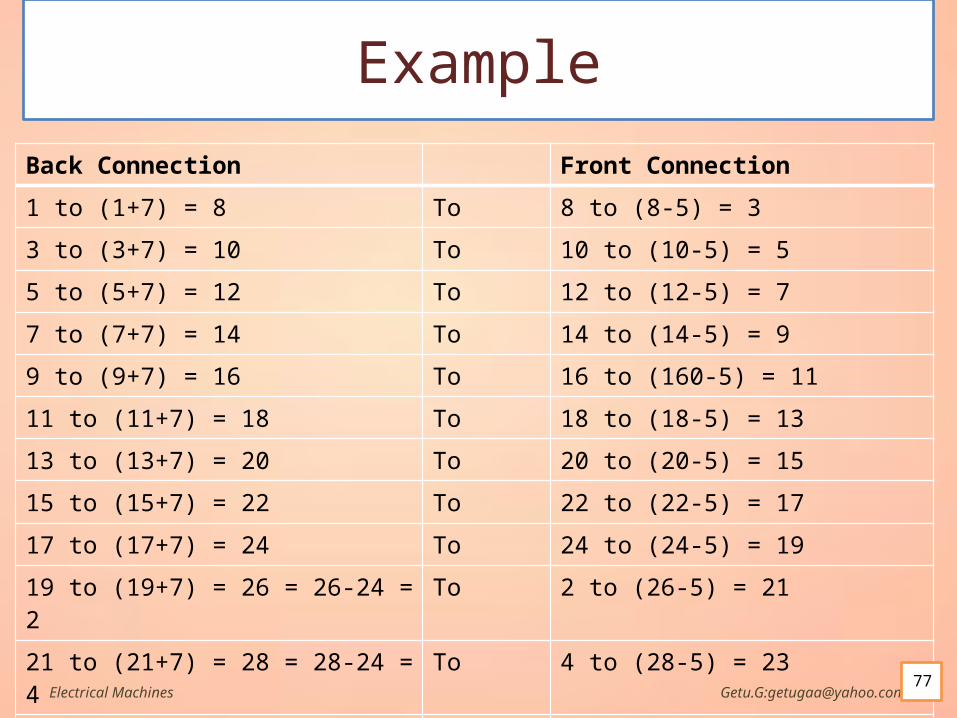
Example
Back Connection Front Connection
1 to (1+7) = 8 To 8 to (8-5) = 3
3 to (3+7) = 10 To 10 to (10-5) = 5
5 to (5+7) = 12 To 12 to (12-5) = 7
7 to (7+7) = 14 To 14 to (14-5) = 9
9 to (9+7) = 16 To 16 to (160-5) = 11
11 to (11+7) = 18 To 18 to (18-5) = 13
13 to (13+7) = 20 To 20 to (20-5) = 15
15 to (15+7) = 22 To 22 to (22-5) = 17
17 to (17+7) = 24 To 24 to (24-5) = 19
19 to (19+7) = 26 = 26-24 = 2 To 2 to (26-5) = 21
21 to (21+7) = 28 = 28-24 = 4 To 4 to (28-5) = 23
23 to (23+7) = 30 = 30-24 = 6 To 6 to (30-5) = 25-24 = 1
Electrical Machines Getu.G:[email protected]
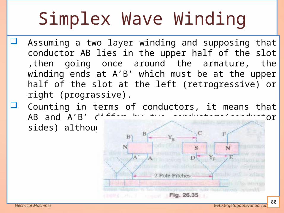
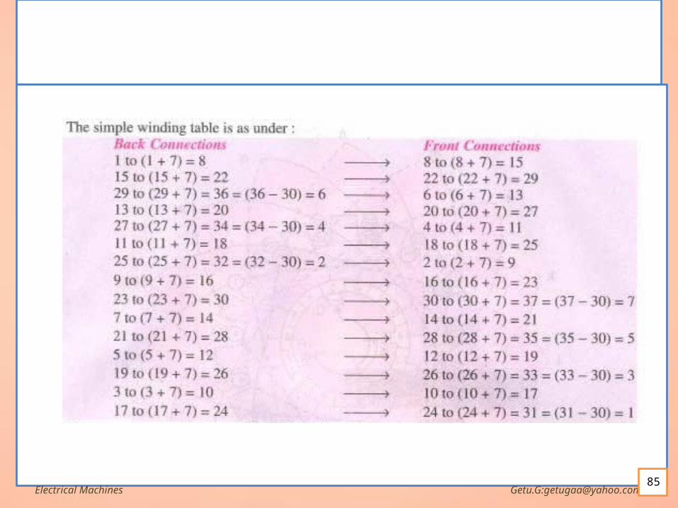
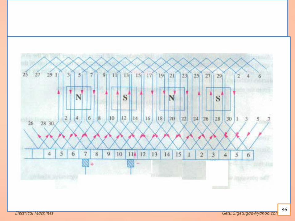
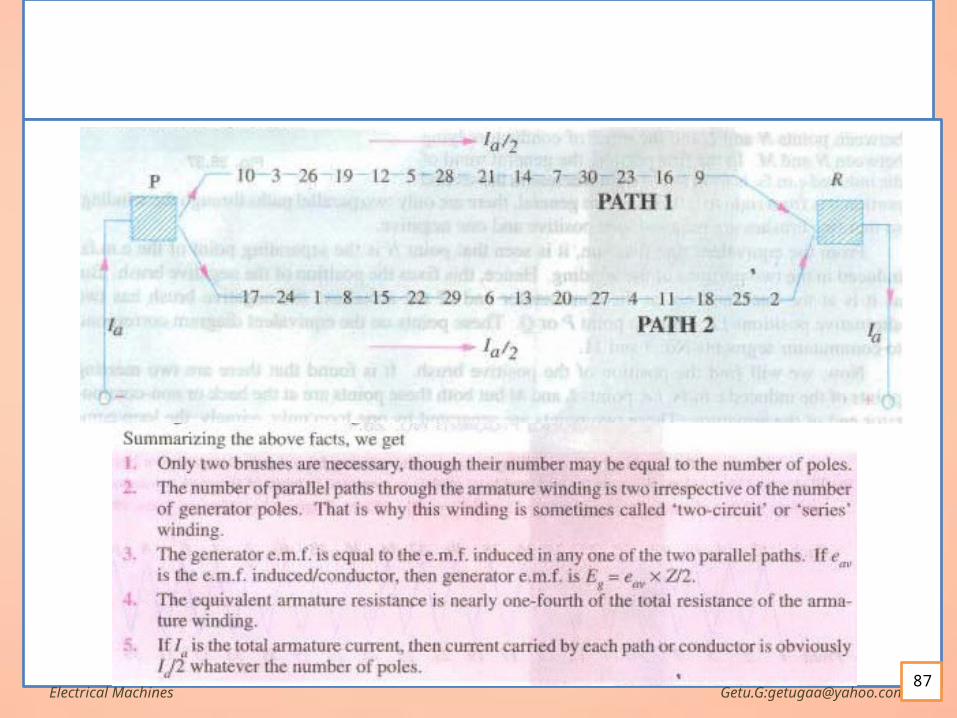
Simplex Wave Winding Assuming a two layer winding and supposing that conductor AB lies in
the upper half of the slot ,then going once around the armature, the winding ends at A’B’ which must be at the upper half of the slot at the left (retrogressive) or right (prograssive).
Counting in terms of conductors, it means that AB and A’B’ differ by two conductors(conductor sides) although they differ by one slot.
Electrical Machines Getu.G:[email protected]

Simplex Wave cont…
Electrical Machines Getu.G:[email protected]
evenbealsomustPYZevenalwaysisPSinceP
ZYThen
sidescoilofnoisZIf
YYYpitchaverageThen
pitchpolethetoequalnearlypitchfrontY
pitchbackY
thenpolesofnoPIf
A
A
FBA
F
B
2,
2
2
,
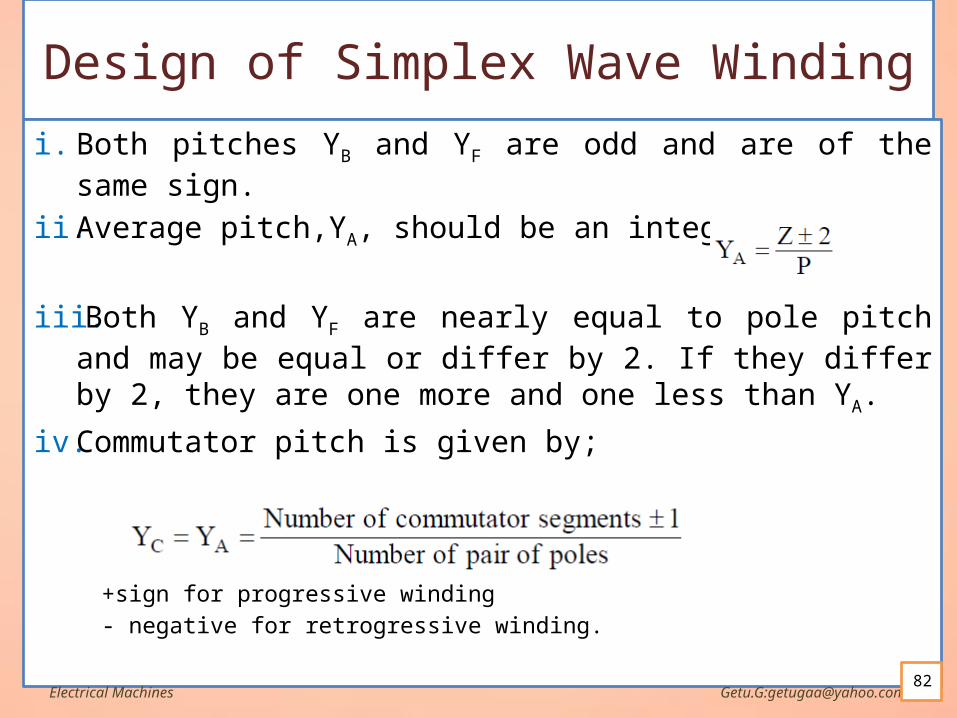
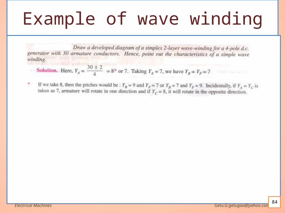
Design of Simplex Wave Windingi. Both pitches YB and YF are odd and are of the same sign.
ii. Average pitch,YA, should be an integer,
iii. Both YB and YF are nearly equal to pole pitch and may be equal or differ by 2. If they differ by 2, they are one more and one less than YA.
iv. Commutator pitch is given by;
+sign for progressive winding
- negative for retrogressive winding.Electrical Machines Getu.G:[email protected]
82
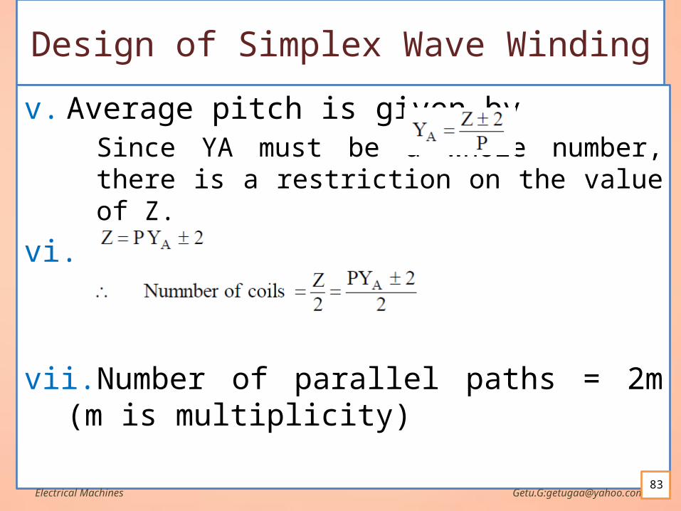
Design of Simplex Wave Winding
v. Average pitch is given by Since YA must be a whole number, there is a restriction on the value of Z.
vi.
vii.Number of parallel paths = 2m (m is multiplicity)
Electrical Machines Getu.G:[email protected]
Electrical Machines Getu.G:[email protected]
Electrical Machines Getu.G:[email protected]
Electrical Machines Getu.G:[email protected]
Dummy windings In a simplex wave winding, the average pitch YA (or
commutator pitch YC) should be a whole number. Sometimes the standard armature punchings available
in the market have slots that do not satisfy the wavw winding requirement so that more coils (usually only one more) are provided than can be utilized.
These extra coils are called dummy or dead coils. The dummy coil is inserted into the slots in the same
way as the others to make the armature dynamically balanced but it is not a part of the armature winding.
Electrical Machines Getu.G:[email protected]
Applications of Lap and Wave Windings
A wave winding has a higher terminal voltage than a lap winding because it has more conductors in series.
A lap winding carries more current than a wave winding because it has more parallel paths.
In small machines, the current-carrying capacity of the armature conductors is not critical and in order to achieve suitable voltages, wave windings are used.
In large machines suitable voltages are easily obtained because of the availability of large number of armature conductors and the current carrying capacity is more critical. lap windings are used
Electrical Machines Getu.G:[email protected]
COMMUTATION PROBLEMS INREAL MACHINES
The commutation process is not as simple in
practice as it seems in theory, because two major effects occur in the real world to dist urb it:
1. Armature reaction
2. Ldi/dt voltages This section explores the nature of these
problems and the solutions employed to mitigate their effects.
Electrical Machines Getu.G:[email protected]
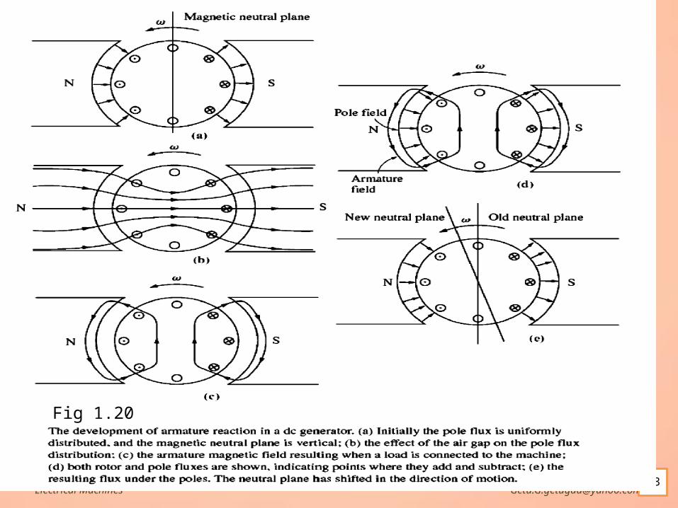
Armature Reaction If the terminals of a DC generator is connected
to load armature current flows in the windings This current flow will produce a magnetic field
of its own, which will distort the original magnetic field from the machine 's poles.
This distortion of the flux in a machine as the load is increased is called armature reaction.
Electrical Machines Getu.G:[email protected]
Armature Reaction cont… Two serious problems of Armature Reaction
The first problem caused by armature reaction is neutral-plane shift.
The magnetic neutral plane is defined as the plane within the machine where the velocity of the rotor wires is exactly parallel to the magnetic flux lines, so that eind in the conductors in the plane is exactly zero.
The brushes are placed at neutral point(zero emf). When neutral point shifts, the brush point is at non zero
emf so arcing and sparking at the brushes occur.
Electrical Machines Getu.G:[email protected]
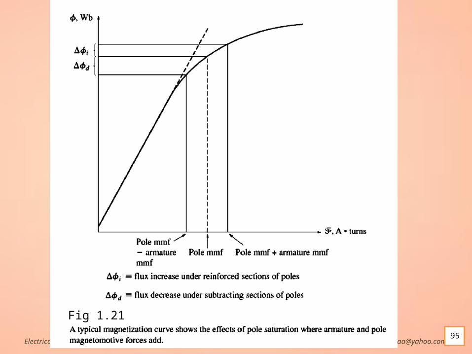
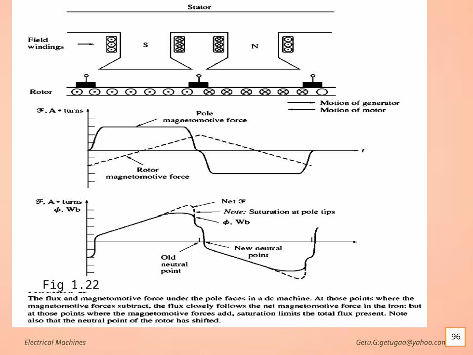
Armature Reaction cont… The second major problem caused by armature reaction is
called flux weakening. At locations on the pole surfaces where the rotor
magnetomotive force adds to the pole magnetomotive force, only a small increase in flux occurs.
But at locations on the pole surfaces where the rotor magnetomotive force subtracts from the pole magnetomotive force, there is a larger decrease in flux.
1he net result is that the total average flux under the entire pole face is decreased
Flux weakening causes problems in both generators and motors. In generators, it simply to reduce the voltage produced In motors, it increases speed and could cause a runaway
condition
Electrical Machines Getu.G:[email protected]
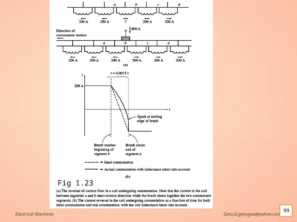
L di/dt Voltages The second major problem is the Ldi/dt voltage that
occurs in commutator segments being shorted out by the brushes, sometimes called inductive kick.
Notice that when a commutator segment is shorted out, the current flow through that commutator segment must reverse.
With even a tiny inductance in the loop, a very significant inductive voltage kick v = Ldi/dt will be induced in the shorted commutator segment.
This high voltage naturally causes sparking at the brushes of the machine, resulting in the same arcing problems that the neutral-plane shift causes.
Electrical Machines Getu.G:[email protected]
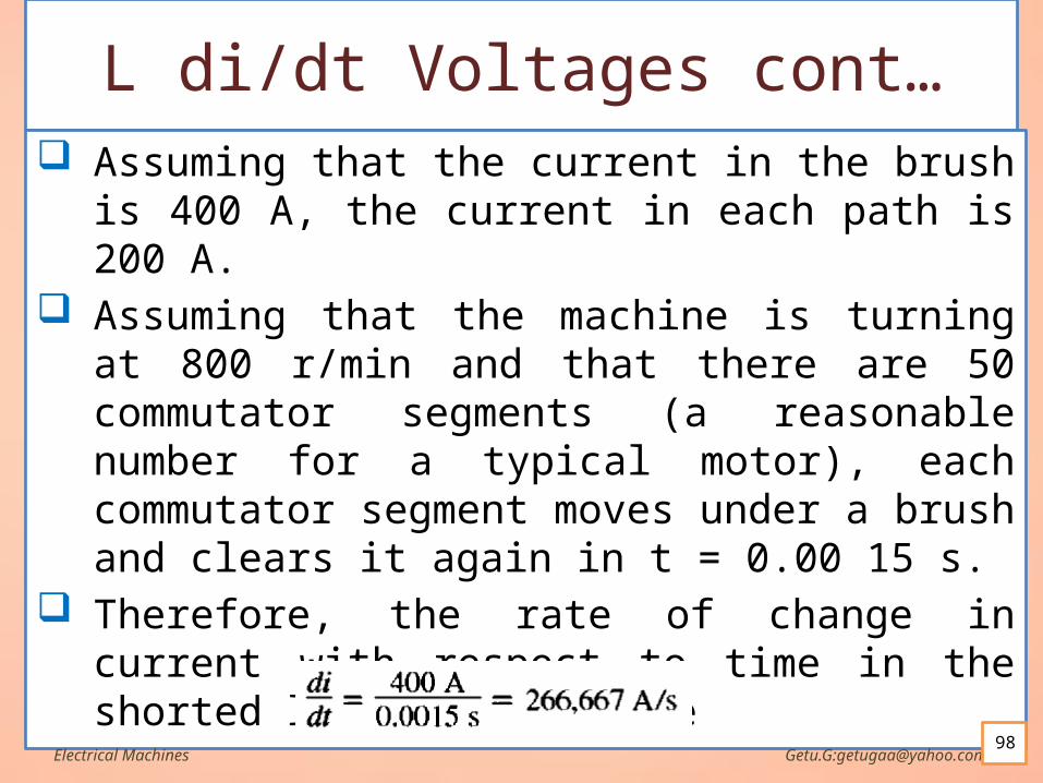
L di/dt Voltages cont… Assuming that the current in the brush is 400 A,
the current in each path is 200 A. Assuming that the machine is turning at 800
r/min and that there are 50 commutator segments (a reasonable number for a typical motor), each commutator segment moves under a brush and clears it again in t = 0.00 15 s.
Therefore, the rate of change in current with respect to time in the shorted loop must average
Electrical Machines Getu.G:[email protected]
Solutions to the Problems with Commutation
Three approaches have been developed to partially or completely correct the problems of armature reaction and L di/dt voltages:
1. Brush shifting
2. Commutating poles or interpoles
3. Compensating windings
Electrical Machines Getu.G:[email protected]
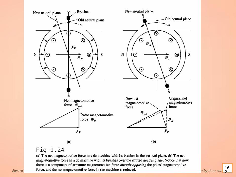
BRUSH SHIFTING. Someone had to adjust the brushes to the new neutral point every time
the load on the machine changed. shifting the brushes may have stopped the brush sparking, but it
actually aggravated the flux-weakening effect of the armature reaction in the machine.
This is true because of two effects:1. The rotor magnetomotive force now has a vector component that opposes the
magnetomotive force from the poles (see Figure 8- 27).
2. The change in armature current distribution causes the flux to bunch up even more at the saturated parts of the pole faces.
Another slightly different approach sometimes taken was to fix the brushes in a compromise position (say, one that caused no sparking at two-thirds of full load).
In this case, the motor sparked at no load and somewhat at full load Today, brush shifting is only used in very small machines that always
run as motors.Electrical Machines Getu.G:[email protected]
COMMUTATING POLES OR INTERPOLES
Because of the requirement that a person must adjust the brush positions of machines as their loads change, another solution to the problem of brush sparking was developed.
The basic idea behind this new approach is that if the voltage in the wires undergoing commutation can be made zero, then there will be no sparking at the brushes.
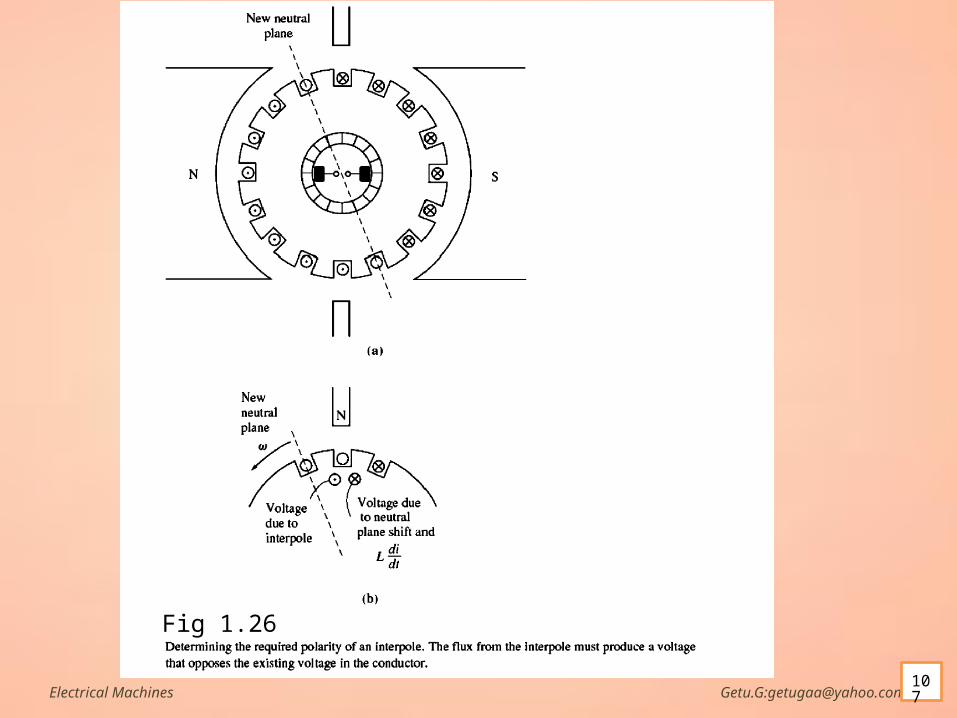
To accomplish this, small poles, called commutating poles or interpoles, are placed midway between the main poles.
These commutating poles are located directly over the conductors being commutated.
By providing a flux from the commutating poles, the voltage in the coils undergoing commutation can be exactly canceled.
Electrical Machines Getu.G:[email protected]
INTERPOLES cont… If the cancellation is exact, then there will be no sparking at
the brushes. The commutating poles do not otherwise change the
operation of the machine, because they are so small that they affect only the few conductors about to undergo commutation.
Notice that the armature reaction under the main pole faces is unaffected, since the effects of the commutating poles do not extend that far.
This means that the flux weakening in the machine is unaffected by commutating poles.
They are connected in series with the windings on the rotor.Electrical Machines Getu.G:[email protected]
104
INTERPOLES cont… As the load increases and the rotor current increases, the magnitude of the
neutral-plane shift and the size of the Ldi/dt effects increase too. Both these effects increase the voltage in the conductors undergoing
commutation. However, the interpole flux increases too, producing a larger voltage in
the conductors that opposes the voltage due to the neutral-plane shift. The net result is that their effects cancel over a broad range of loads. The interpoles must induce a voltage in the conductors undergoing
commutation that is opposite to the voltage caused by neutral-plane shift and L di/dt effects.
Note that interpoles work for both motor and generator operation The current both in its rotor and in its interpoles reverses direction.
Electrical Machines Getu.G:[email protected]
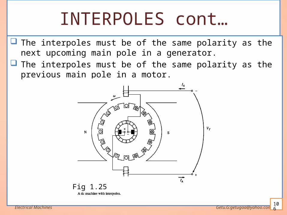
INTERPOLES cont… The interpoles must be of the same polarity as the next upcoming main pole
in a generator. The interpoles must be of the same polarity as the previous main pole in a
motor.
Electrical Machines Getu.G:[email protected]
Fig 1.25
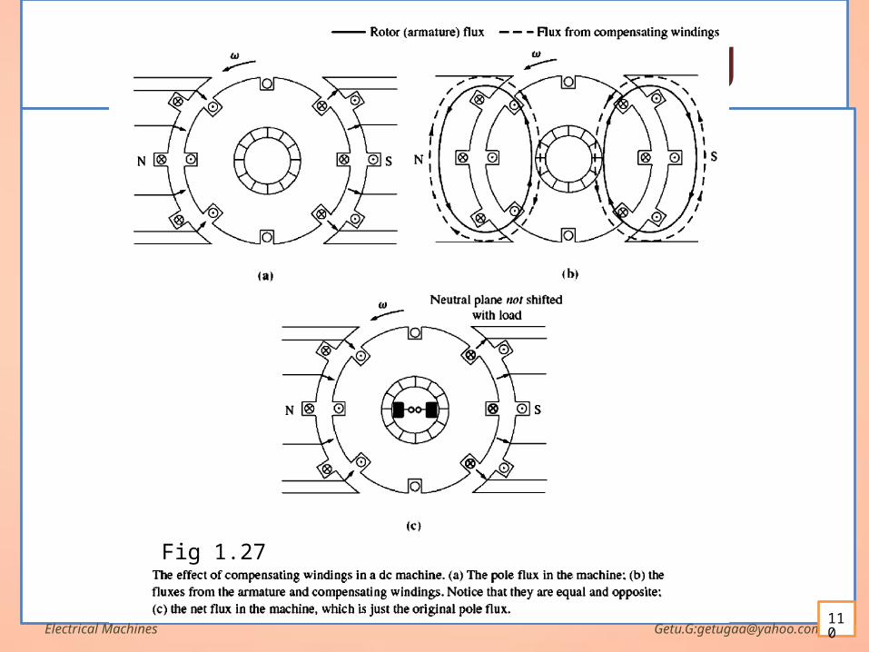
COMPENSATING WINDINGS For very heavy, severe duty cycle motors, the flux-weakening problem can
be very serious. To completely cancel armature reaction and thus eliminate both neutral-
plane shift and flux weakening, a different technique was developed. This third technique involves placing compensating windings in slots
carved in the faces of the poles parallel to the rotor conductors, to cancel the distorting effect of armature reaction.
These windings are connected in series with the rotor windings, so that whenever the load changes in the rotor, the current in the compensating windings changes, too.
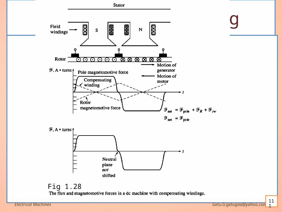
Notice that the magnetomotive force due to the compensating windings is equal and opposite to the magnetomotive force due to the rotor at every point under the pole faces.
The resulting net magnetomotive force is just the magnetomotive force due to the poles, so the flux in the machine is unchanged regardless of the load on the machine.Electrical Machines Getu.G:[email protected]
108
COMPENSATING WINDINGS cont The major disadvantage of compensating windings is that
they are expensive, since they must be machined into the faces of the poles.
Any motor that uses them must also have interpoles, since compensating windings do not cancel Ldi/dt effects.
The interpoles do not have to be as strong, though, since they are canceling only L dildt voltages in the windings, and not the voltages due to ne utral-plane shifting.
Because of the expense of having both compensating windings and interpoles on such a machine, these windings are used only where the extremely severe nature of a motor 's duty demands them.
Electrical Machines Getu.G:[email protected]


![[XLS] · Web viewstomato 2011 oanaelena31@yahoo.com baronul2007@gmail.com geopaicu@yahoo.com pacurarusmaranda@yahoo.com paraschivrodica2001@yahoo.com CIOBANU CĂTĂLINA-CARMEN, COSTIN](https://img.pdfslide.net/doc/110x75/5aca839b7f8b9aa1298dc050/xls-viewstomato-2011-oanaelena31yahoocom-baronul2007gmailcom-geopaicuyahoocom.jpg)