Embed Size (px)
Citation preview

02-30000-00
Cylinder block Piston protrusion 0.475 to 0.745mm -
Piston ring TOP ring end gap 0.20 to 0.35 mm -
2nd ring end gap 0.35 to 0.50 mm -
3rd ring end gap 0.2 to 0.40 mm -
Offset 0.3mm -
Head gasket Piston protrusion 0.475 to 0.540 1.2t -
0.541 to 0.649 1.3t -
0.650 to 0.745 1.4t -
1. ENGINE ASSEMBLY
Unit Description Specification Remark
Cylinder head Height 131.9 to 132.1 mm -
Flatness below 0.1 mm -
Valve protrusion Intake valve 0.6 to 1.0 mm -
Exhaust valve 0.6 to 1.0 mm -
Flatness on manifold side
Intake manifold 0.08 mm -
Exhaust manifold 0.08 mm -
Connecting rod End play 0.5 to 0.31 mm -
Camshaft Axial end play Intake 0.1 to 0.35 mm -
Exhaust 0.1 to 0.35 mm -
Camshaft position sensor
Distance between Camshaft position sensor and sprocket
0.20 to 1.80 mm -
02-4
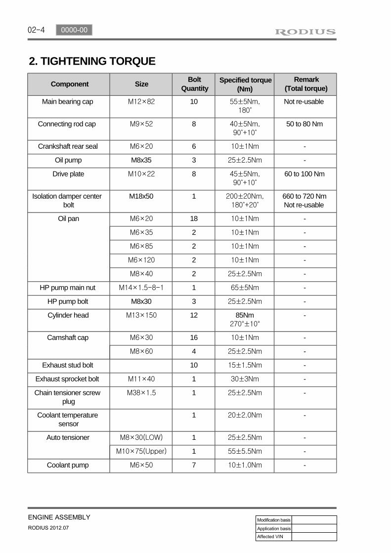
2. TIGHTENING TORQUE
Component SizeBolt
QuantitySpecified torque
(Nm)Remark
(Total torque)
Main bearing cap M12×82 10 55±5Nm,180˚
Not re-usable
Connecting rod cap M9×52 8 40±5Nm,90˚+10˚
50 to 80 Nm
Crankshaft rear seal M6×20 6 10±1Nm -
Oil pump M8x35 3 25±2.5Nm -
Drive plate M10×22 8 45±5Nm,90˚+10˚
60 to 100 Nm
Isolation damper center bolt
M18x50 1 200±20Nm,180˚+20˚
660 to 720 NmNot re-usable
Oil pan M6×20 18 10±1Nm -
M6×35 2 10±1Nm -
M6×85 2 10±1Nm -
M6×120 2 10±1Nm -
M8×40 2 25±2.5Nm -
HP pump main nut M14×1.5-8-1 1 65±5Nm -
HP pump bolt M8x30 3 25±2.5Nm -
Cylinder head M13×150 12 85Nm270°±10°
-
Camshaft cap M6×30 16 10±1Nm -
M8×60 4 25±2.5Nm -
Exhaust stud bolt 10 15±1.5Nm -
Exhaust sprocket bolt M11×40 1 30±3Nm -
Chain tensioner screw plug
M38×1.5 1 25±2.5Nm -
Coolant temperature sensor
1 20±2.0Nm -
Auto tensioner M8×30(LOW) 1 25±2.5Nm -
M10×75(Upper) 1 55±5.5Nm -
Coolant pump M6×50 7 10±1.0Nm -

02-50000-00
Component SizeBolt
QuantitySpecified torque
(Nm)Remark
(Total torque)
Hot water inlet pipe M6×12 2 10±1Nm -
Alternator M10×90 1 (lower) 25±2.5Nm -
M10×116 1 (upper) 46±4.6Nm -
A/C compressor M8×85 4 25±2.5Nm -
A/C bracket M6×25 4 10±1Nm -
Intake manifold M8×35 2 25±2.5Nm -
M8×110 6 25±2.5Nm -
Oil filter module M8×40 6 25±2.5Nm -
M8×20 1 25±2.5Nm -
M8×140 2 25±2.5Nm -
Knock sensor M8×28 2 20±5Nm -
Cam position sensor M8×14 1 10~14Nm -
T-MAP pressure sensor
M6×20 1 10±1Nm -
Exhaust manifold M8 10 40±4Nm -
Turbocharger M8 3 25±2.5Nm -
T/C support bolt 1 25±2.5Nm -
T/C support nut M8 1 25±2.5Nm -
T/C oil supply pipe M6(block side) 1 10±1.0Nm -
M6(turbo side) 1 17±2.0Nm -
T/C oil return pipe M6×16(turbo side)
2 10±1Nm -
M6×16(block side)
2 10±1Nm -
EGR valve M8×22 3 25±2.5Nm -
EGR pipe bolt(Intake side)
M8×16 2 10±1.0Nm -
EGR pipe bolt(EGR cooler side)
M8×16 2 25±2.5Nm -
Idle pulley/Tensioner pulley
1 45±4.5Nm -
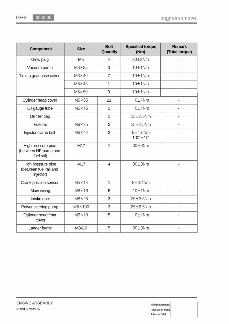
02-6
Cylinder head cover M6×35 21 10±1Nm -
Oil gauge tube M6×16 1 10±1Nm -
Oil filter cap 1 25±2.5Nm -
Fuel rail M8×25 2 25±2.5Nm -
Injector clamp bolt M6×44 2 9±1.0Nm130˚±10˚
-
High pressure pipe (between HP pump and
fuel rail)
M17 1 30±3Nm -
High pressure pipe (between fuel rail and
injector)
M17 4 30±3Nm -
Crank position sensor M5×14 1 8±0.4Nm -
Main wiring M6×16 5 10±1Nm -
Intake duct M8×25 3 25±2.5Nm -
Power steering pump M8×100 3 25±2.5Nm -
Cylinder head front cover
M6×10 5 10±1Nm -
Ladder frame M8x16 5 30±3Nm -
Component Size Bolt Quantity
Specified torque (Nm)
Remark(Total torque)
Glow plug M5 4 20±2Nm -
Vacuum pump M8×25 3 10±1Nm -
Timing gear case cover M6×40 7 10±1Nm -
M6×45 1 10±1Nm -
M6×50 3 10±1Nm -

02-70000-00
3. CHECK AND INSPECTION
1) Cylinder
(1) Compression pressure test
Specified value▶
Compression ratio 16.5 : 1
Test condition at normal operating temperature (80˚C)
Compression pressure Standard 32 bar
Minimum 18 bar
Differential limit between cylinders Maximum 3 bar
The compression pressure test is to check the conditions of internal components (piston, piston ring, intake and exhaust vale, cylinder head gasket). This test provides current engine operating status.
Measurement▶
Warm the engine up to normal operating temperature (80°C).
Disconnect the fuel rail pressure sensor connector to cut off the fuel injection.Remove the air cleaner duct and glow plugs.
---
Place the diagram sheet to compression pressure tester and install it into the plug hole.
1.
Before cranking the engine, make sure that the test wiring, tools and persons are keeping away from moving components of engine (e.g., belt and cooling fan).Park the vehicle on the level ground and apply the parking brake.Do not allow anybody to be in front of the vehicle.
-
--
02-8
(2) Cylinder pressure leakage test
If the measured value of the compression pressure test is not within the specifications, perform the cylinder pressure leakage test.
Specified value▶
Perform this test in the sequence of firing order.Do not test the cylinder pressure leakage with wet type test procedure. (do not inject the engine oil into the combustion chamber)
--
Test condition: normal engine operating temperature (80˚C)
Specified value
Whole engine below 25%
at valve and cylinder head gasket below 10%
at piston ring below 20%
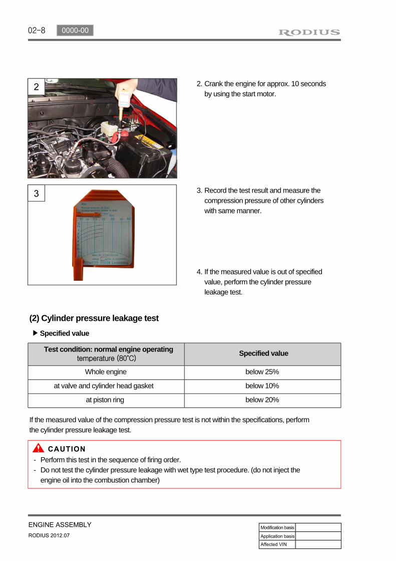
Crank the engine for approx. 10 seconds by using the start motor.
2.
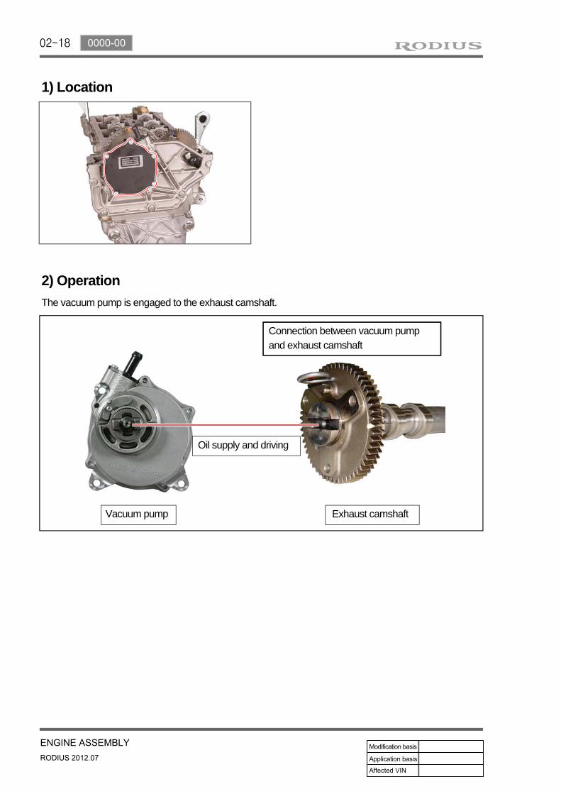
Record the test result and measure the compression pressure of other cylinders with same manner.
3.
If the measured value is out of specified value, perform the cylinder pressure leakage test.
4.

02-90000-00
Position the piston at TDC and measure the piston protrusion from crank case mating surface.
(3) Piston protrusion check
Specified value 0.475~0.745mm
Measure it at both ends of crankshaft.-

02-10
2) Cylinder Head
(1) Cylinder head mating surface check
Specified value▶
Measure the cylinder head height "A".1.
Insert the valves into the valve guides and measure the recesses.
2.
Valve recess “a” 0.6 to 1.0mm
(2) Cylinder head pressure Leak test
Immerse the cylinder head with the pressure plate into warm water (approx. 60°C) and pressurize
with compressed air to 2 bar.
If the height is less than the limit, the cylinder head must be replaced.
-
If the measured value is out of the specified range, machine the valve seat as much as necessary until the specified value is achieved.
-
Total height "A" 131.9 to 132.1 mm
Minimum height after machining 131.9 mm
Flatness Longitudinal direction 0.1 / 150
Transverse direction 0.15
Parallel deviation of cylinder head below 0.1 mm
Peak-to valley of surface Rmax 7 Rz 6.3
valve recess "a" Intake valve 0.6 to 1.0 mm
Exhaust valve 0.6 to 1.0 mm

02-110000-00
4. GUIDELINES ON ENGINE SERVICETo prevent personal injuries and vehicle damages that can be caused by mistakes during engine and unit inspection/repair and to secure optimum engine performance and safety after service works, basic cautions and service work guidelines that can be easily forgotten during engine service works are described in.
Cautions before service worksFor safe and correct works, you must observe the working procedures and instructions in this manual. And, use the designated tools as follow:Engine stand / Heavy duty engine jackTo prevent the engine from starting abruptly, do not allow anybody to get in the vehicle while servicing in engine compartment.Before work on engine and each electrical equipment, be sure to disconnect battery negative (-) terminal.Before service works, be sure to prepare the works by cleaning and aligning work areas.Do not allow the foreign material get into the fuel injection system.When removing the engine, use only the safety hook on engine and engine hanger. Do not support the bottom of oil pan with a jack.
Engine and accessoriesCompletely drain the engine oil, coolant and fuel from engine before removal.Before disassembling/assembling the engine components, carefully read the working procedures in this manual.Make sure to keep the specified tightening torques during installation.Clean and properly lubricate the parts before reassembly.Carefully check that there are not any interference while servicing.
▶
-
-
-
---
▶
--
---

02-12
Electrical equipment▶
Electric devices should be handled more carefully.Currently, the engine has a lot of electric devices. there could be poor engine performance, incomplete combustion and other abnormal symptoms due to short circuit or poor contact.
Before work on engine and each electrical equipment, be sure to disconnect battery negative (-) terminal.When replacing the electric device, use only genuine part and check the conditions of connections and grounds. Loosened connection or ground make cause a fire and personal injury.
-
-
Fuel and lubrication system▶
Do not allow the fluid and engine oil to make contact with the body paintwork and hoses.If work on the fluid system such as fuel and oil, working area should be well ventilated and smoking should be prohibited.Gasket or seal on the fuel/lubrication system should be replaced with new ones and bolts and nuts should be tightened as specified.After removal/installation works, be sure to check whether there is leak on the connecting section.
--
-
-
If fine dust or foreign material enters into DI engine's fuel system, there can be serious damages in HP pump and injectors. Thus, be sure to plug the inlets of removed fuel line components with cap and protect removed parts not to be contaminated with dirt. (Refer to cleanness in this manual while working on DI engine fuel system)

02-130000-00
D20DTR Engine
1. BELT LAYOUTIt is single drive type and uses FEAD (Front End Accessories Drive) design to make a compact layout.
Components▶
HPS(Hydraulic Power Steering)
1 Crankshaft pulley (DDU)
2 Auto tensioner
3 Tensioner pulley
4 Vacuum pump
5 A/C compressor pulley
6 Alternator pulley
7 Water pump pulley
8 Idle pulley #1
9 Idle pulley #2
10 Power steering pump pulley

02-14
The strut type tensioner automatically adjusts the belt tension to provide the reliability and durability for the system. And, the belt tension is decreased to minimize the friction loss and improve the belt operating noise.
1) Crankshaft Pulley (Isolation Damper)
(1) Overview
(2) Sectional drawing
Axial & radial bearing
Sleeve
Hub
Isolation pulley rubber
Pulley
Damper rubber
Inertia ring

02-150000-00
(3) Features
Rubber damper: Decrease crankshaft torsionImprove belt NHV: Reduce unbalance speed to crankshaft due to irregular combustionMinimize noise: Anti-vibration from crankshaft and beltPost bonded type rubber damper: Improve durability of rubber damper
1.2.3.4.

02-16
2) Belt Tensioner
(1) Overview
The torque deviation from crankshaft affects the components in belt drive system and the belt movement. The auto tensioner system is to adjust this deviation automatically.In D20DTR engine, one of the mechanical tensioner, pivot damped tensioner is used to keep the damping force, system reliability and durability. The single belt drive system needs to use the automatic belt tensioning device to transfer the power to pulleys effectively. To get this, the tensioner uses the spring and damping unit.
(2) Location
Belt tensioner

02-170000-00
Vacuum pump
Pump capacity: 210 cc/revCamshaft speed: 375 to 3,000 rpmLubrication temperature: -40 to 155°COil: 5W30Drive type: Driven by exhaust Camshaft sprocket
EGR cooler bypass valve
This valve is controlled by ECU. When the engine is cooled, the exhaust gas goes to combustion chamber without passing through EGR cooler because the valve is closed by vacuum pressure.
2. VACUUM PUMPVacuum pump generates the vacuum pressure and supplies it to EGR cooler bypass solenoid. This pump is single vane type and displacement is 210 cc/rev. The lubrication oil is supplied through the hole in hollow shaft.
Components▶
Brake booster and naster cylinder
02-18
1) Location
2) Operation
The vacuum pump is engaged to the exhaust camshaft.
Connection between vacuum pump and exhaust camshaft
Oil supply and driving
Vacuum pump Exhaust camshaft

02-190000-00
Rear mounting insulator
2WD M/T 2WD A/T 4WD A/T
P/N: 31900-21M20 P/N: 31900-21A20 P/N: 31900-21A40
3. ENGINE MOUNTINGD20DTR engine uses 3-point mounting type that supports the engine and transmission simultaneously.
Components▶
Front mounting insulator (Left side)
Location Insulator
Front mounting insulator (Right side)
Location Insulator

02-20
Appearance Type and function
Front mounting insulator (Left side) Type: Rubber mountingFunction: Supports the powertrain
Front mounting insulator (Right side) Type: Rubber mountingFunction: Supports the powertrain
Rear mounting insulato Type: Rubber mountingFunction: Supports the powertrain
1) Functions

02-210000-00
4. INTAKE/EXHAUST MANIFOLD
1) Intake Manifold
Intake manifold is installed on the cylinder head with 8 bolts. The variable swirl valve is introduced to improve the EGR gas mixture and turbulence in combustion chamber and to decrease the exhaust gas.
2) Exhaust Manifold
Exhaust manifold is installed on the cylinder head with 10 stud bolts and nuts. EGR port is integrated
in cylinder head.
Components▶
Components▶
For detailes, refer to Chapter "Intake System".*
For detailes, refer to Chapter "Exhaust System".*
Exhaust manifold
Intake manifold

02-22
Rear view
5. CYLINDER HEAD COVER AND OIL SEPARATOR
The cylinder head cover is made by high strength plastic to reduce the weight. The multi twist type oil separator improves the oil consumption.
Components▶
1) Cylinder Head Cover
Cylinder head cover
Cylinder head cover

02-230000-00
2) Oil Separator
Oil separator separates the particle in blow-by gas to minimize the engine oil consumption and reduces the inflow oil from intake system into the combustion chamber. The separated oil returns to oil pan through cylinder head.
Oil separator
Blow-by outlet hose
(1) Overview
(2) Layout

02-24
Vacuum pump driveHP pump drive gear
Cylinder head gasket
Camshaft position sensor
Components▶
Cylinder head
Cylinder head contains cam position sensor, vacuum pump, intake manifold, exhaust manifold and valve assembly. Vacuum pump and the high pressure (HP) pump are driven by Camshaft and valves are install in vertical direction. This enables the compact layout in cylinder head assembly.
6. CYLINDER HEAD
Finger follower & HLA Camshaft sprocketIntake/exhaust Camshafts

02-250000-00
Location of Expansion Plugs
1) Cylinder Head
(1) Overview
The cylinder is made by gravity casting and the water jacket is integrated type.The cylinder oil passage is drilled and sealed by cap.The Camshaft bearing cap is also made by casting and installed on the cylinder head.
(2) Features
Front
Oil gallery expansion plug (M10)
Coolant expansion plug (M21)
Intake side
Rear

02-26
Intake/Exhaust Camshafts
2) Camshaft
(1) Overview
Hollow type camshaft contains cam, octagon cam, HP pump gear and intake/exhaust gears.Camshaft operates the intake/exhaust valves, vacuum pump and HP pump, and transfers the engine oil to vacuum pump through the internal oil passage.
(2) Location
Exhaust Camshaft Exhaust Camshaft
Thrust journal
Intake Camshaft
Closed flow type water jacket (improving cooling performance)▶
Octagon cam (for tooling)
Connected to vacuum pump

02-270000-00
3) Valve Assembly (Installed in Cylinder Head)
(1) Features
Automatic valve clearance adjuster by hydraulic pressure (Maintenance Free) - Hydraulic lashOptimized adjustment of valve clearance reduces the valve noise.Roller type finger follower reduces the friction loss.Vertical installation.Simple and compact design reduces the moving operation (improving valve following and fuel consumption at high speed)
1.2.3.4.5.
(2) Arrangement
Hydraulic lash adjuster
Upper valve spring retainer
Lower valve spring retainer
Valve spring
Exhaust valve Intake valve
Finger follower

02-28
4) Cylinder Head Gasket
(1) Features
Sealing the cylinder gas pressure - Peak pressure: 190 barMinimizing the distortion of engine structure (cylinder head, block): profile stopper, backland stopperMaterial: MLS (Multi Layer Steel), Gasket (3 layers)Thickness of gasket: 3 types (1.2 /1.3 /1.4 mm)
1.2.
3.4.
(2) Thickness of cylinder head gasket
There are three types of gasket to managing the compression ratio.
Piston protrusion▶
Piston protrusion Thickness
0.475 to 0.540 mm 1.2t
0.541 to 0.649 mm 1.3t
0.650 to 0.745 mm 1.4t
Thickness marking
Ex: 1.3t
02-290000-00
1) Chain Drive
(1) Overview
The drive chain is single chain drive system with simple design and variable performance, and it utilizes the hydraulic tensioner to reduce the wave impact generated by the chain. This chain is light weight and has high durability through single bush chain. Shoulder bolts are used for better NHV.
7. CHAIN AND GEAR DRIVE SYSTEMD20DTR engine uses single stage chain drive system. Timing chain drives the exhaust side and gear drive the intake side. Timing chain is single bush type. Upper chain drives HP pump connected to intake Camshaft by driving exhaust cam shift sprocke, and lower chain drives oil pump to lubricate the engine.
02-30
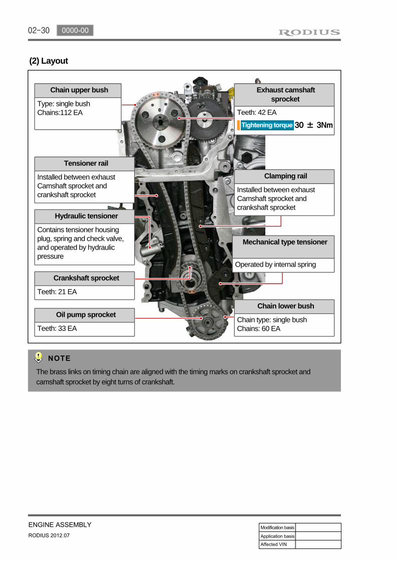
(2) Layout
Chain upper bush
Type: single bushChains:112 EA
Tensioner rail
Installed between exhaust Camshaft sprocket and crankshaft sprocket
Hydraulic tensioner
Contains tensioner housing plug, spring and check valve, and operated by hydraulic pressure
Crankshaft sprocket
Teeth: 21 EA
Oil pump sprocket
Teeth: 33 EA
Chain lower bush
Chain type: single bushChains: 60 EA
Mechanical type tensioner
Operated by internal spring
Clamping rail
Installed between exhaust Camshaft sprocket and crankshaft sprocket
Exhaust camshaft sprocket
Teeth: 42 EA
The brass links on timing chain are aligned with the timing marks on crankshaft sprocket and camshaft sprocket by eight turns of crankshaft.
02-310000-00
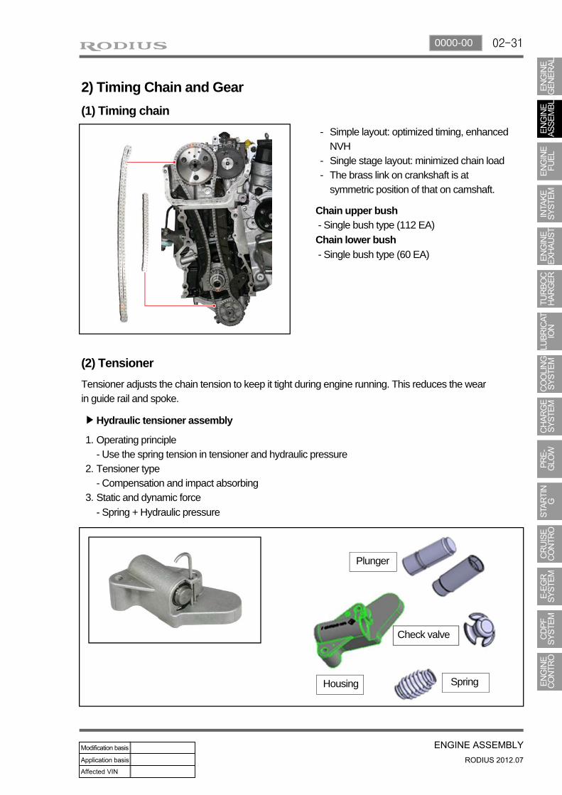
2) Timing Chain and Gear
(1) Timing chain
Simple layout: optimized timing, enhanced NVHSingle stage layout: minimized chain loadThe brass link on crankshaft is at symmetric position of that on camshaft.
-
--
Chain upper bush - Single bush type (112 EA)
Chain lower bush
- Single bush type (60 EA)
(2) Tensioner
Tensioner adjusts the chain tension to keep it tight during engine running. This reduces the wear in guide rail and spoke.
Operating principle- Use the spring tension in tensioner and hydraulic pressureTensioner type- Compensation and impact absorbingStatic and dynamic force
- Spring + Hydraulic pressure
1.
2.
3.
Plunger
Housing Spring
Check valve
Hydraulic tensioner assembly▶

02-32
Clamping guide railTensioner guide rail
(3) Mechanical Tensioner Assembly
Operating principle- Use only spring tension
Tensioner type- Compensation and impact absorbing
Static and dynamic force- Spring
(4) Guide rail
The guide rail is used for optimizing the movement of chain drive system. And it also prevents the chain from contacting each other when the chain is loose, and reduces the chain wear.The guide rail is made of plastic, nylon, Teflon, etc. The guide rail is specially required when the distance between two spokes is too great. It pushes the chain with constant force so that the chain can work smoothly. The guide rail is fitted by pins.

02-330000-00
Screw plug
Oil sealTiming gear case cover
Timing gear case cover (TGCC)
(5) Timing gear case cover

02-34
FeaturesMajor function: Protecting the chain drive system, minor function: Shielding the chain noise.Install crankshaft front seal and screw plug on the timing gear case cover.
▶
--
Do not touch the inner lip of crankshaft front seal.Be careful not to damage the screw thread when removing the lock pin to release the chain tensioner.Be careful not to damage the O-ring when installing the screw plug.
--
-
A671 997 01 46Crankshaft front seal
Location of chain tensioner screw plug

02-350000-00
Oil pan sassembly
8. OIL PAN
The oil pan in D20DTR engine improves the NVH. Especially, the oil draining is much easier than before.
Components▶

02-36
9. DUAL MASS FLYWHEEL (DMF) & DRIVE PLATE
1) Overview
Flywheel is installed on crankshaft. When starting the engine, this functions as follows:
Reducing the irregular speed of crankshaft due to unbalanced combustion -> Improving the power train NVH, Improving the driving performanceReducing the clutch noise by using ball bearingImproving the durability of DMF by using strong arch spring
-
-
-
2) Layout
Spring guide
Drive plate
Primary cover
Primary flywheel
Internal/external ring Secondary flywheel
Ring gear

02-370000-00
Torque change curve of engine and drive shaft
Compression stroke Combustion stroke
Small changes from engine (k):Damper increases the torque changes to clutch
Large changes from engine (j):Damper decreases the torque changes to transaxle by absorbing the impact
3) Operation
Compensating the irregular operation of engine: The secondary flywheel operates almost evenly so does not cause gear noisesThe mass of the primary flywheel is less than conventional flywheel so the engine irregularity increases more (less pulsation absorbing effect).Transaxle protection function: Reduces the torsional vibration to powertrain (transaxle) by reducing the irregularity of engine.
-
-
-
02-38
4) Features
Reduced vibration noise from the powertrain by blocking the torsional vibrationsEnhanced vehicle silence and riding comforts: reduced engine torque fluctuationReduced shifting shocksSmooth acceleration and deceleration
----
5) Advantages
Improved torque response by using 3-stage type spring: Strengthens the torque response in all ranges (low, medium, and high speed) by applying respective spring constant at each range.Stable revolution of the primary and secondary wheel by using planetary gear: Works as auxiliary damper against spring changesLess heat generation due to no direct friction against spring surface: Plastic material is covered on the spring outer surfaceIncreased durability by using plastic bushing (extends the lifetime of grease)
-
-
-
-
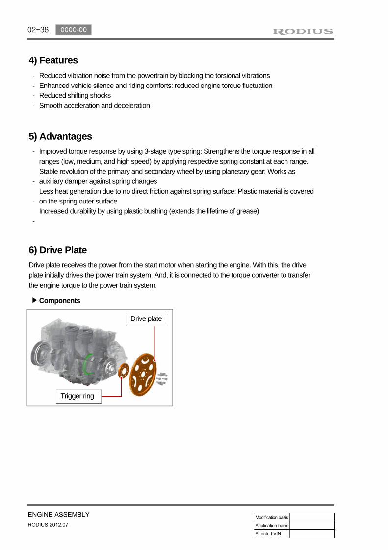
6) Drive Plate
Drive plate receives the power from the start motor when starting the engine. With this, the drive plate initially drives the power train system. And, it is connected to the torque converter to transfer the engine torque to the power train system.
Trigger ring
Drive plate
Components▶

02-390000-00
10. PISTON/CRANKSHAFT/CYLINDER BLOCKThe crankshaft and the cylinder block convert the compression pressure to the rotating energy.
Components▶
Cylinder block
Piston
Connecting rod
Crankshaft

02-40
1) Piston
(1) Overview
Piston assembly contains piston, #1 ring, #2 ring, oil ring, piston pin and snap ring. The expansion energy from engine is transferred to the crankshaft through connecting rod to convert the linear movement to rotating energy.
(2) Layout
#1 ring
Oil ring
Snap ring
#2 ringMaterial: B2+
Skirt coating: MoS2
Piston cooling gallery for connecting rod
Wide bawl type (CR 16.5)
Cooling jet

02-410000-00
(3) Functions
Piston transfers the combustion energy from engine to connecting rod. Especially in the direct injection engine such as D20DTF, it provides the combustion space and largely effects to the engine performance and exhaust gas.
Piston ring#1 ring (Top ring) : Prevents the high pressurized combustion gas from leaking into crank chamber, and prevents the engine oil getting into combustion chamber. #2 ring: Scrapes the engine oil on the cylinder bore, and prevents the leaked combustion gas from #1 ring from leaking into the crank chamber. Oil ring: Scrapes the engine oil on the cylinder bore.
Piston pinConnects the piston the connecting rod, and transfers the linear movement of piston to connecting rod to convert it to rotating energy
Snap pinLocks the piston pin.
▶
-
-
-
▶
-
▶
-
(4) Assembling the piston
Install the piston rings with the "Y" mark on the ring facing upwards.Position the end gap of #1 ring at 180˚
away from the end gap of #1 ring.Position the end gap of oil ring at 180˚
away from the end gap of coil spring, and position the end gap of oil ring at 90˚ away
from the end gap of #2 ring.
1.
2.
3.

02-42
Selecting piston oversize
Top of piston Top of cylinder block
EnginePiston Cylinder bore
Part NO Marking NO. -
D20DTF
671 030 06 17 - -
671 037 07 01 A A
671 037 08 01 X X
671 037 09 01 B B
671 037 10 01 +5 -
671 037 11 01 +10 -

02-430000-00
2) Connecting Rod
(1) Overview
Connecting rod converts the reciprocating movement of piston to the rotating movement of crankshaft. The big end is connected to connecting rod bearing and the crank pin journal, and the small end is connected to the piston pin.
(2) Components
Connecting rod cap bolt
Connecting rod upper bearing
Connecting rod
Piston pin bush
Connecting lower bearing
Connecting rod cap

02-44
No
Connecting rod/ Bore
diameter in bigend
Upper bearing Lower bearing Journal diameter of crank pin
Oil clearance of
bearingGrade Bearing thickness
Grade Bearing thickness
1
54.600 R
1.804 B
1.812
50.935
0.017
1.808 1.815 0.063
2 Y
1.808 Y
1.809 0.016
54.614
1.812 1.812
50.960
0.062
3 B
1.812 R
1.806 0.015
1.816 1.809 0.061
Min. 0.015
Max. 0.063
(3) Selection of crankshaft pin journal bearing
The connecting rod bearing contains 3 sets of 3 grades in upper and lower sections.Three sets in the table below have nearly same oil clearance (0.015~0.063 mm) of bearing.Identification: Coloe mark on bearing side surface
---
Oil clearance of connecting rod bearing

02-450000-00
3) Crankshaft
(1) Overview
Crankshaft is installed on the cylinder block.
(2) Arrangement
Crankshaft main bearing upper Crankshaft main bearing upper
Upper thrust bearing
Crankshaft main bearing lower Crankshaft main bearing lower
Lower thrust bearing
Crank pin journal Main journal

02-46
Bottom of cylinder block
Selection of upper main bearing
Mating surface of crankshaft sprocket
Selection of lower main bearing
(3) Selection of crankshaft main bearing
Mark Color Thickness of main bearing (mm)
V Violet +0.030 +0.025
W White +0.025 +0.020
R Red +0.020 +0.015
Y Yellow +0.015 +0.010
B Blue +0.010 +0.005
2.25
2.25
2.25
2.25
2.25
Selection of bearing according to pin punch & color
Mark Color Thickness of main bearing
* Blue 66.500~66.506
** Yellow 66.506~66.513
*** Red 66.513~66.519

02-470000-00
4) Cylinder Block
(1) Overview
The major dimensions in D20DTR are similar to D20DTR engine. It has two mountingbosses for knock sensor and meets the requirements for EURO5 regulation.
(2) Layout
Right side Cylindrical pin
Expansion plug
Screw plug

02-48
Left side Expansion plug
(3) Features
For simple manufacturing, the crankcase blow-by gas passage and the oil return hole are made by casting on the cylinder block.

02-490000-00
The bottom side of water jacket is desgined as sine wave to strengthen the structure of crankcase. The main flow of coolant starts from outlet port of water pump and goes along the longitudinal direction of engine. The coolant passage from cylinder head to inlet port of water pump is integrated in cylinder head.
The engine oil from oil pump is supplied to the main oil gallery through oil channel, oil filter module and cross bore in cylinder block without using external pipes. This oil is supplied to main bearing, cylinder head and MBU. And, it is sprayed to the chain through the chain tensioner connected to cross bore.
Crankcase cross bore for oil supply
Water jacket core


![AD-A149 341 RESEARCH ON ADAPTIVE ANTENNA TECHNIQUES … · 1960s. Capon et.al. [1.5] and Lacoss [1.61 addressed adaptive signal processing in seismic arrays. while Shor [1.7] worked](https://img.pdfslide.net/doc/110x75/5f082d3d7e708231d420b86e/ad-a149-341-research-on-adaptive-antenna-techniques-1960s-capon-etal-15-and.jpg)