Embed Size (px)
Citation preview

1
FPGA Lab
School of Electrical Engineering and Computer Science
Ohio University, Athens, OH 45701, U.S.A.
An Entropy-based Learning Hardware Organization Using FPGAAn Entropy-based Learning Hardware Organization Using FPGA
Janusz Starzyk and Yongtao Guo March 19, 2001

2
Outline
IntroductionIntroduction Entropy-based EvaluatorEntropy-based Evaluator Hardware ImplementationHardware Implementation Synthesis & PerformanceSynthesis & Performance SummarySummary

3
IntroductionWHAT ARE NEURAL NETWORKS ?
Main functionLike human brain
FEATURES OF NEURAL NETWORKS ?
Self-Organizing Learning.Fault tolerant. Fast run but not fast to learn.Particularly suited to problems.Can be trained to generate non-linear mappings.

4
Feed-forward (FF) Threshold-controlled input (TCI) Threshold-controlled outputs (TCO) Entropy based evaluator Information deficiency
Introduction --Self Organizing Learning

5
Entropy-based Evaluator
Entropy based information index
cPsP
)log()log(
logmax
max1
s sPsPscPs c scPE
c cPcPE
E
EI
Here, , , represent the probabilities of each class, attribute probability and joint probability respectively.
cP sP scP

6
Subspaces information deficiency
Entropy-based Evaluator
ccc
ssssc
s csc
ss PP
PPPP
E
E
)log(
)log()log(
max

7
Necessary Approximation
Mult(a,b)=E(Sub(L(a)+L(b),B)) multiplicationDivd(a,b)=E(Sub(L(a),L(b))) division
L(a) returns the location (starting from 0) of the most significant bit position of a,
E(a) forces 1 on a-th bit position ( a modification of this operation forces 1 on a, a-2, a-4 etc. bit positions).
B word length
Entropy-based Evaluator - Information Index

8
1 1.5 2 2.5 3 3.5 4 4.5 50
0.05
0.1
0.15computation comparation with quantization and lut
I
Threshold Index
caculatedhardware simulated
Figure Structural Simulation
Entropy-based Evaluator - Structural Simulation
9
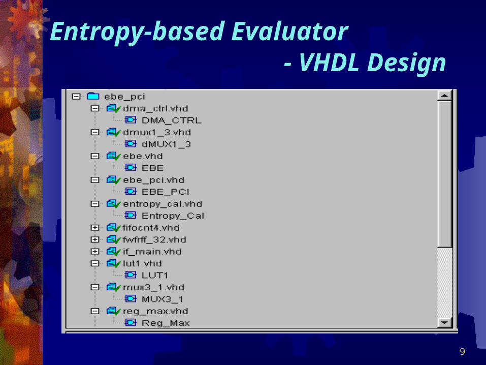
Entropy-based Evaluator - VHDL Design

10
CLK
DATA
Start
Request
Done
N_1
N_2
OE
MuxSelect1
MuxSelect2
in_data
Threshold
in_threshold
Curr_Entropy
Max_Entropy
out_data
OutThreshold
State
Nextstate
34 45 56 67 78 89 9A AB BC CD DE
0E 17
3 3 3 3 3 3 3 3 3 3 3
0E 17 1E 1B 10 06
34 45 56 67 78 89 9A AB BC CD DE
0E 17
0E 17 1E 1B 10 06
1 1 1 1 1 1 1 1 1 1 1
67
EF
1E
0
0
00
EF
1E
00
3
0
ns6 8 10 12 14 16 18 20 22 24 26 28
Fig. VHDL Simulation at RTL
Entropy-based Evaluator - VHDL Simulation at RTL

11
EBE hardware model: Memory circuit (LUT) Comparator unit ECU Two registers
Hardware Implementation
Threshold
MaxInfo
LUTLUT
ECU
ECUComparator
Unit
ComparatorUnit
EBE
OE
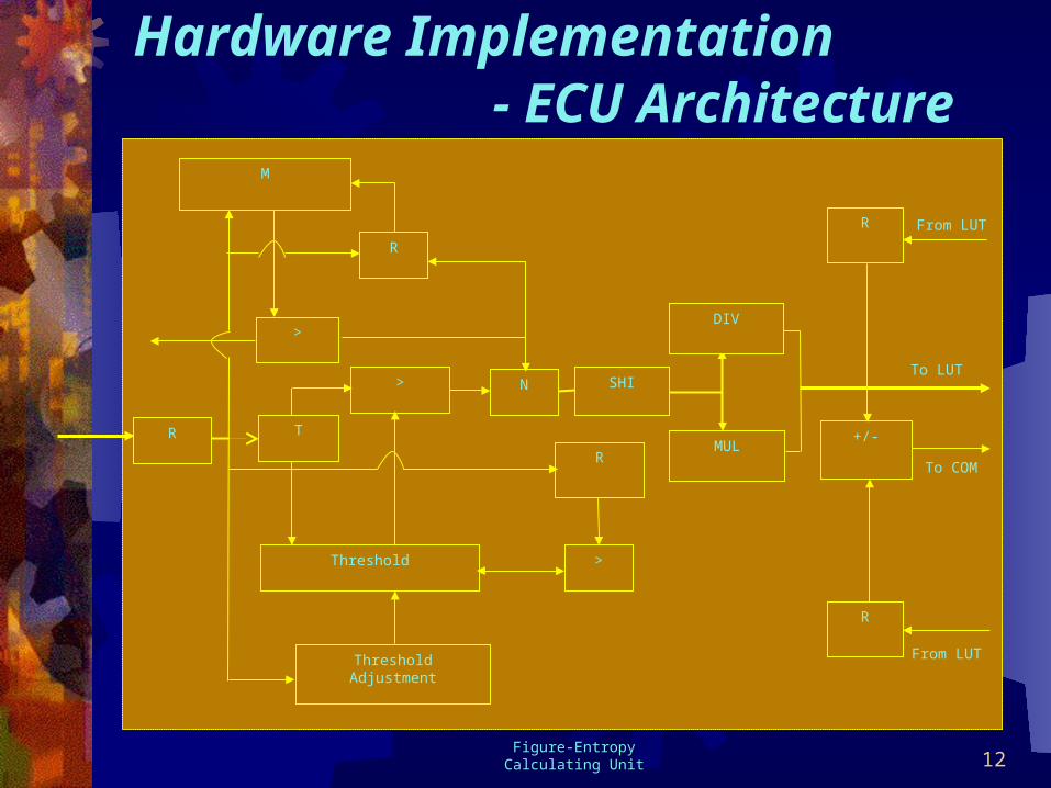
12
Hardware Implementation - ECU Architecture
From LUT
From LUT
To LUT
To COM
M
R
>
Threshold
N
T
>
R
>
ThresholdAdjustment
RMUL
DIV
SHI
R
+/-
R
Figure-Entropy Calculating Unit

13
Other components: Control Unit System clock, state transfer signals, handshake signals.
MUX & DMUX Parallel process of the multi-feature data in the input classes.
Display Unit Real-time monitor for the data transfer.
EBE Interface Between FIFO control unit, PCI bus and EBE for rapid data
transfer and easy online system debugging.
Hardware Implementation

14Figure- FPGA-based Architecture
Ou
tput
PCI Interface C
orePC
I Interface Core
FIF
O C
trlF
IFO
Ctrl
EB
E Interface
EB
E Interface
R1
R2
Control UnitControl Unit
DMUX
PCI
Display
ReqStartDone
Threshold
MaxInfo
LUTLUT
ECU
ECUComparator
Unit
ComparatorUnit
EBE
OE
MUX
SEL SEL
Hardware Implementation

15
Hardware Implementation
Reconfigurable Advantage Exploit cases where operation can
be bound and then reused a large number of times.
Customization of operator type, width, and interconnect.
Flexible low overhead exploitation of application parallelism.

16
Synthesis & Performance-Implementation Flow
Check
VHDL RTL Simulation
Schematic
Capture
.bit fileCheck
vvs
Download
Optimization
Figure- Implementation Flow

17
Synthesis & Performance--Map design to Virtex

18
Synthesis & Performance--FPGA Map
19
Synthesis & Performance--Schematic

20
Synthesis & Performance--FPGA Floorplan
Vendor: Xilinx
Family: VIRTEX
Device: V800BG432
Speed: -4
Number of External GCLKIOBs 1 out of 4 25%
Number of External IOBs 47 out of 316 14%
Number of BLOCKRAMs 4 out of 28 14%
Number of SLICEs 463 out of 9408 4 %
Number of DLLs 1 out of 4 25%
Number of GCLKs 1 out of 4 25%
Number of TBUFs 256 out of 9632 2%
Number of flip-flops: 336
Minimum period: 24.838ns
Maximum frequency: 40.261MHz
Total equivalent gate count for design: 88,186
Additional JTAG gate count for IOBs: 2,304

21
Summary
Self-Organizing AlgorithmSelf-Organizing Algorithm
Matlab & VHDL SimulationMatlab & VHDL Simulation
Hardware ArchitectureHardware Architecture
Synthesis Synthesis
Analog CircuitsAnalog Circuits