Embed Size (px)
Citation preview

8/3/2019 1 Framed Static Structures
http://slidepdf.com/reader/full/1-framed-static-structures 1/31
Framed structures

8/3/2019 1 Framed Static Structures
http://slidepdf.com/reader/full/1-framed-static-structures 2/31
Objective
Stress / strain
Tensile testing
Understand different types of frames;
Redundancy
Stability Calculate forces in frames.

8/3/2019 1 Framed Static Structures
http://slidepdf.com/reader/full/1-framed-static-structures 3/31
Definitions
Tensile force
Compressive force Shear force
Stress
Strain
Shear stress Shear strain
Elasticity
Elasticity modulus

8/3/2019 1 Framed Static Structures
http://slidepdf.com/reader/full/1-framed-static-structures 4/31
Material Testing.
Materials are tested
to determine their:
± Physical & Mechanical
properties.
± Physical condition.
± & therefore their
suitability for a
particular application.

8/3/2019 1 Framed Static Structures
http://slidepdf.com/reader/full/1-framed-static-structures 5/31
Categories of material test
± Non Destructive
Testing.
± Destructive Testing.

8/3/2019 1 Framed Static Structures
http://slidepdf.com/reader/full/1-framed-static-structures 6/31
Destructive Testing.
The material is tested
until it is:
Deformed
Damaged
Fractured

8/3/2019 1 Framed Static Structures
http://slidepdf.com/reader/full/1-framed-static-structures 7/31
Destructive Testing.
± Readings recorded.
± Readings comparedwith standards.
± Material properties
identified.

8/3/2019 1 Framed Static Structures
http://slidepdf.com/reader/full/1-framed-static-structures 8/31
Destructive Testing.
Destructive testing
undertaken to
determine a
material¶s:
± Tensile strength.
± Toughness.
± Hardness.
± Ductilit .

8/3/2019 1 Framed Static Structures
http://slidepdf.com/reader/full/1-framed-static-structures 9/31
Tensile Testing.
± Material in
TENSION when
stretched.
± Stretching called
TENSILE LOAD.

8/3/2019 1 Framed Static Structures
http://slidepdf.com/reader/full/1-framed-static-structures 10/31
Tensile Testing.
± Tensile test is carried
out on a
± TENSOMETER.

8/3/2019 1 Framed Static Structures
http://slidepdf.com/reader/full/1-framed-static-structures 11/31
Tensile Testing.
± Throughout test
readings of:
± applied load and
± Extension
± recorded.
8/3/2019 1 Framed Static Structures
http://slidepdf.com/reader/full/1-framed-static-structures 12/31
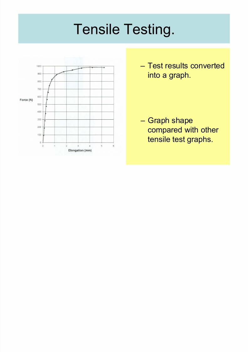
± Test results converted
into a graph.
± Graph shape
compared with other tensile test graphs.
Tensile Testing.

8/3/2019 1 Framed Static Structures
http://slidepdf.com/reader/full/1-framed-static-structures 13/31
Tensile Testing.
± Throughout test
readings of:
± applied load and
± extension
± recorded.
8/3/2019 1 Framed Static Structures
http://slidepdf.com/reader/full/1-framed-static-structures 14/31
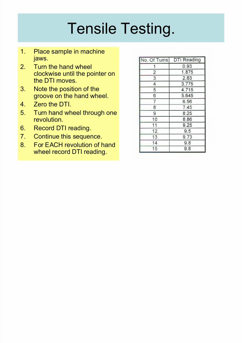
Tensile Testing.
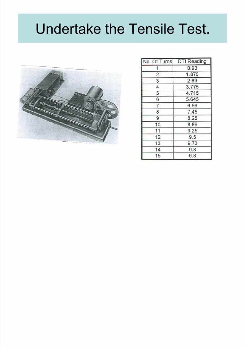
1. Place sample in machine jaws.
2. Turn the hand wheelclockwise until the pointer onthe DTI moves.
3. Note the position of thegroove on the hand wheel.
4. Zero the DTI.
5. Turn hand wheel through onerevolution.
6. Record DTI reading.7. Continue this sequence.
8. For EACH revolution of handwheel record DTI reading.
8/3/2019 1 Framed Static Structures
http://slidepdf.com/reader/full/1-framed-static-structures 15/31
Undertake the Tensile Test.

8/3/2019 1 Framed Static Structures
http://slidepdf.com/reader/full/1-framed-static-structures 16/31
Converting the results.
± Specimen elongation given by subtracting DTI reading from number of turns.
eg. 3 turns giving a DTI reading of 2.83(3 ± 2.83 = 0.17mm extension).
± Force is given by DTI reading x 100.
eg. DTI reading = 2.83 x 100 =
283 Newtons force.

8/3/2019 1 Framed Static Structures
http://slidepdf.com/reader/full/1-framed-static-structures 17/31
Typical Force / Extension Curve.

8/3/2019 1 Framed Static Structures
http://slidepdf.com/reader/full/1-framed-static-structures 18/31
Tensile test practice
Do handout questions.
Perform tensile test in lab.

8/3/2019 1 Framed Static Structures
http://slidepdf.com/reader/full/1-framed-static-structures 19/31
Truss ± Framed structure

8/3/2019 1 Framed Static Structures
http://slidepdf.com/reader/full/1-framed-static-structures 20/31
Uses:
Bridges -A
Roof- B
Joints are assumed to
be frictionless pin-joints
8/3/2019 1 Framed Static Structures
http://slidepdf.com/reader/full/1-framed-static-structures 21/31
Parts
Each part is called a ³member´.
They are either in tension or compression,depending on the structure and loading.
In compression they are called struts
In tension they are called ties

8/3/2019 1 Framed Static Structures
http://slidepdf.com/reader/full/1-framed-static-structures 22/31
Plane trusses
In groups of 2, build a truss:
± 3 members, 3 joints, length=200mm, 150mm,150mm
± 4 members, 4 joints, 200mm, 200mm, 250mm,
100mm.
± 5 members, 4 joints, 200mm, 200mm, 250mm,
100mm, 5 member to fit across opposite corners.

8/3/2019 1 Framed Static Structures
http://slidepdf.com/reader/full/1-framed-static-structures 23/31
Stability?
Which of the trusses you made are stable,
and which are unstable? Can you think of a formulae that would tell us
if it going to be stable?
What if we add an additional member to
example 3 without additional joints?

8/3/2019 1 Framed Static Structures
http://slidepdf.com/reader/full/1-framed-static-structures 24/31
Redundancy
If we have a stable structure and we add one
more member, that member will beredundant .

8/3/2019 1 Framed Static Structures
http://slidepdf.com/reader/full/1-framed-static-structures 25/31
Statically determinate:
Structure j m
Unstable:
m+3<2j
Stable with no
redundancy:
m+3=2j
Stable with
redundancy:
m+3>2j

8/3/2019 1 Framed Static Structures
http://slidepdf.com/reader/full/1-framed-static-structures 26/31
Analysis of frameworks:
Example 1

8/3/2019 1 Framed Static Structures
http://slidepdf.com/reader/full/1-framed-static-structures 27/31
Analysis of frameworks:

8/3/2019 1 Framed Static Structures
http://slidepdf.com/reader/full/1-framed-static-structures 28/31
8/3/2019 1 Framed Static Structures
http://slidepdf.com/reader/full/1-framed-static-structures 29/31
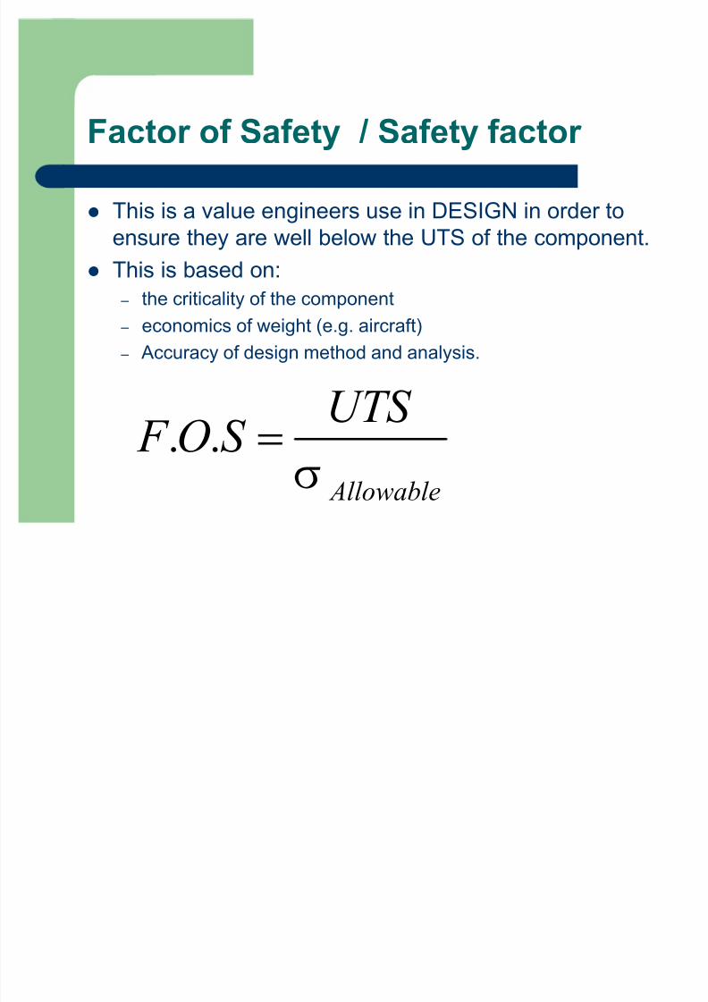
Factor of Safety / Safety factor
This is a value engineers use in DESIGN in order to
ensure they are well below the UTS of the component.
This is based on:
± the criticality of the component
± economics of weight (e.g. aircraft)
± Accuracy of design method and analysis.
. .
Allowable
UTS F O S
W
!

8/3/2019 1 Framed Static Structures
http://slidepdf.com/reader/full/1-framed-static-structures 30/31
Factor of Safety / Safety factor
But often we do not want the component to deform
permanently so,
. .
yield
Allowable
F O S
W
W
!

8/3/2019 1 Framed Static Structures
http://slidepdf.com/reader/full/1-framed-static-structures 31/31
Exercise sheet: Framed structures


![Gioncu [Framed Structures. Ductility and Seismic Response - 2000]](https://img.pdfslide.net/doc/110x75/5532c8424a79599f5e8b4753/gioncu-framed-structures-ductility-and-seismic-response-2000.jpg)