Embed Size (px)
Citation preview
Interflex Datensysteme GmbH 1/9
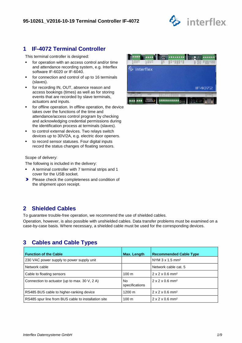
1 IF-4072 Terminal Controller This terminal controller is designed: for operation with an access control and/or time
and attendance recording system, e.g. Interflex software IF-6020 or IF-6040.
for connection and control of up to 16 terminals (slaves).
for recording IN, OUT, absence reason and access bookings (times) as well as for storing events that are recorded by slave terminals, actuators and inputs.
for offline operation. In offline operation, the device takes over the functions of the time and attendance/access control program by checking and acknowledging credential permissions during the identification process at terminals (slaves).
to control external devices. Two relays switch devices up to 30V/2A, e.g. electric door openers.
to record sensor statuses. Four digital inputs record the status changes of floating sensors.
Scope of delivery: The following is included in the delivery: A terminal controller with 7 terminal strips and 1
cover for the USB socket. Please check the completeness and condition of
the shipment upon receipt.
2 Shielded Cables To guarantee trouble-free operation, we recommend the use of shielded cables. Operation, however, is also possible with unshielded cables. Data transfer problems must be examined on a case-by-case basis. Where necessary, a shielded cable must be used for the corresponding devices.
3 Cables and Cable Types
Function of the Cable Max. Length Recommended Cable Type 230 VAC power supply to power supply unit NYM 3 x 1.5 mm²
Network cable Network cable cat. 5
Cable to floating sensors 100 m 2 x 2 x 0.6 mm²
Connection to actuator (up to max. 30 V, 2 A) No specifications
2 x 2 x 0.6 mm²
RS485 BUS cable to higher-ranking device 1200 m 2 x 2 x 0.6 mm²
RS485 spur line from BUS cable to installation site 100 m 2 x 2 x 0.6 mm²
95-10261_V2016-10-19 Terminal Controller IF-4072
Interflex Datensysteme GmbH 2/9
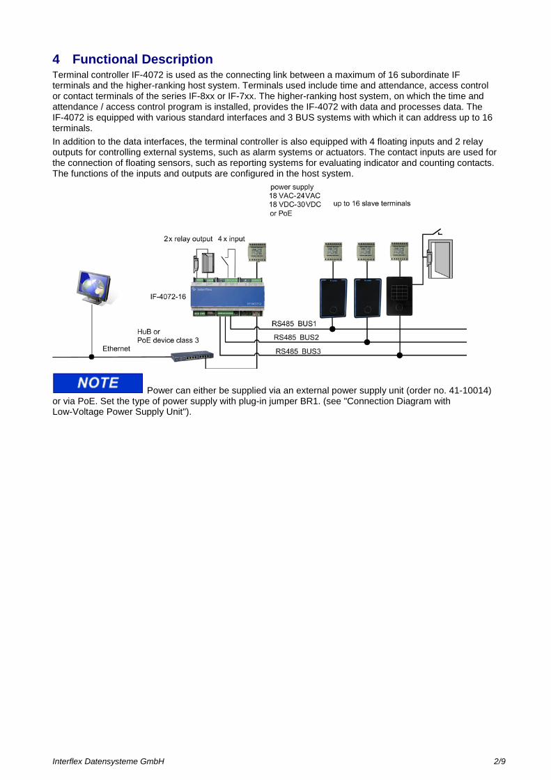
4 Functional Description Terminal controller IF-4072 is used as the connecting link between a maximum of 16 subordinate IF terminals and the higher-ranking host system. Terminals used include time and attendance, access control or contact terminals of the series IF-8xx or IF-7xx. The higher-ranking host system, on which the time and attendance / access control program is installed, provides the IF-4072 with data and processes data. The IF-4072 is equipped with various standard interfaces and 3 BUS systems with which it can address up to 16 terminals. In addition to the data interfaces, the terminal controller is also equipped with 4 floating inputs and 2 relay outputs for controlling external systems, such as alarm systems or actuators. The contact inputs are used for the connection of floating sensors, such as reporting systems for evaluating indicator and counting contacts. The functions of the inputs and outputs are configured in the host system.
Power can either be supplied via an external power supply unit (order no. 41-10014) or via PoE. Set the type of power supply with plug-in jumper BR1. (see "Connection Diagram with Low-Voltage Power Supply Unit").
Interflex Datensysteme GmbH 3/9
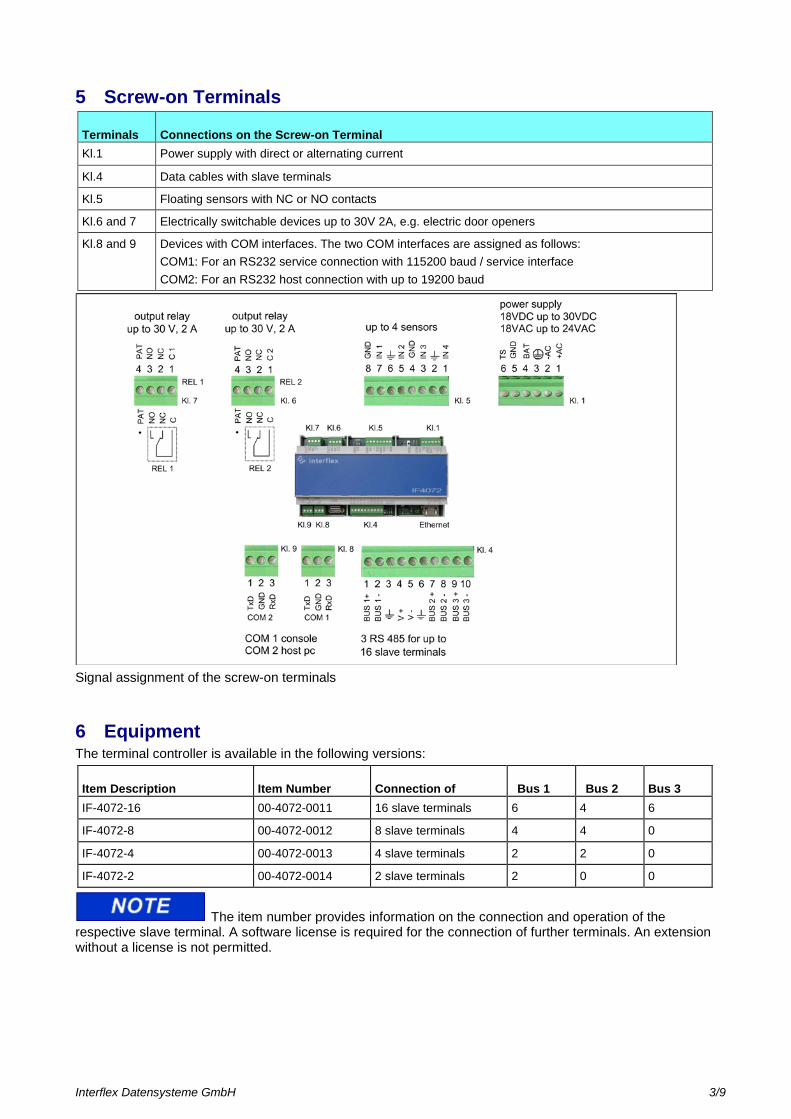
5 Screw-on Terminals
Terminals Connections on the Screw-on Terminal Kl.1 Power supply with direct or alternating current
Kl.4 Data cables with slave terminals
Kl.5 Floating sensors with NC or NO contacts
Kl.6 and 7 Electrically switchable devices up to 30V 2A, e.g. electric door openers
Kl.8 and 9 Devices with COM interfaces. The two COM interfaces are assigned as follows: COM1: For an RS232 service connection with 115200 baud / service interface COM2: For an RS232 host connection with up to 19200 baud
Signal assignment of the screw-on terminals
6 Equipment The terminal controller is available in the following versions:
Item Description Item Number Connection of Bus 1 Bus 2 Bus 3 IF-4072-16 00-4072-0011 16 slave terminals 6 4 6
IF-4072-8 00-4072-0012 8 slave terminals 4 4 0
IF-4072-4 00-4072-0013 4 slave terminals 2 2 0
IF-4072-2 00-4072-0014 2 slave terminals 2 0 0
The item number provides information on the connection and operation of the respective slave terminal. A software license is required for the connection of further terminals. An extension without a license is not permitted.
Interflex Datensysteme GmbH 4/9
6.1 Interface for the connection to a host computer Connections to a host computer are possible via: Ethernet 10BaseT/ 100BaseT (automatic setting) 2 RS232 with up to 19200 baud for service purposes 3 RS485 data cables The network connection of the terminal controller conforms to standards. A standard cable or patch cable can be used for connection. The two RS232 interfaces and the three RS485 bus cables are connected via screw-on terminals.
6.2 Interface for slave terminal connection Three RS485 interfaces are available for the connection of slave terminals. A maximum of 8 slave terminals can be connected per interface. Combined, the three interfaces can address a maximum of 16 terminals.
6.3 Inputs and relays Four digital inputs are used for the connection of floating sensors. The inputs can be used as event or counting contacts. Two relays with NO/NC contacts switch external devices up to 30 V / 2 A, e.g. electric door openers.
6.4 USB interface The USB interface is reserved for future applications.
6.5 Service interface The following interfaces are available for service purposes and for configuration: Ethernet. Access is possible via TELNET or SSH connection. RS232 with 115200 baud. 8 data bit, no parity See also: How to Connect a Service Device with a COM Interface
Interflex Datensysteme GmbH 5/9
7 Connection and Modes of Operation
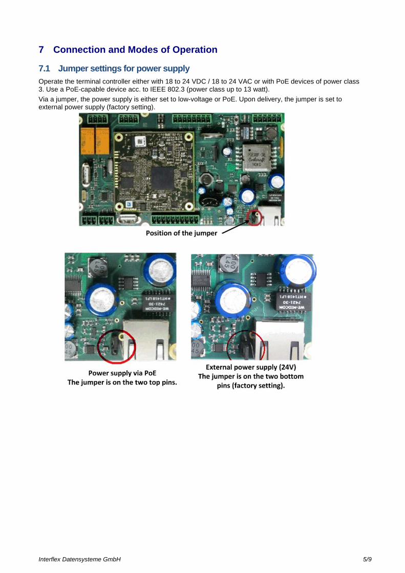
7.1 Jumper settings for power supply Operate the terminal controller either with 18 to 24 VDC / 18 to 24 VAC or with PoE devices of power class 3. Use a PoE-capable device acc. to IEEE 802.3 (power class up to 13 watt). Via a jumper, the power supply is either set to low-voltage or PoE. Upon delivery, the jumper is set to external power supply (factory setting).
Interflex Datensysteme GmbH 6/9
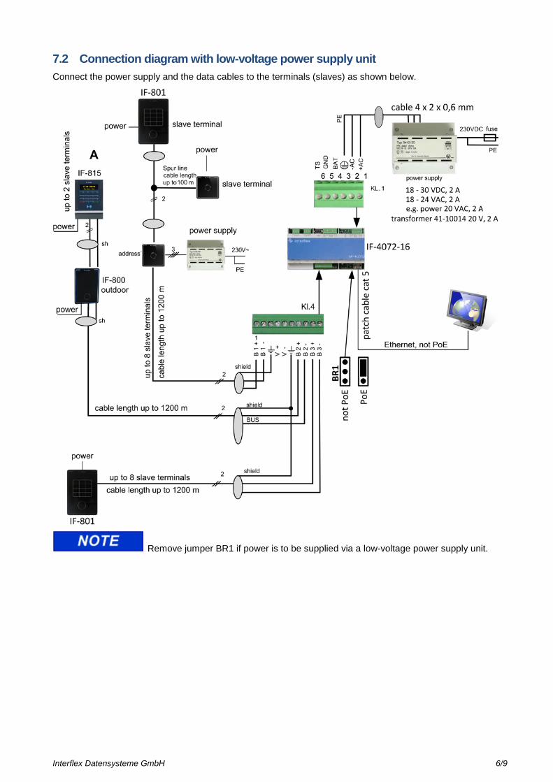
7.2 Connection diagram with low-voltage power supply unit Connect the power supply and the data cables to the terminals (slaves) as shown below.
Remove jumper BR1 if power is to be supplied via a low-voltage power supply unit.
Interflex Datensysteme GmbH 7/9
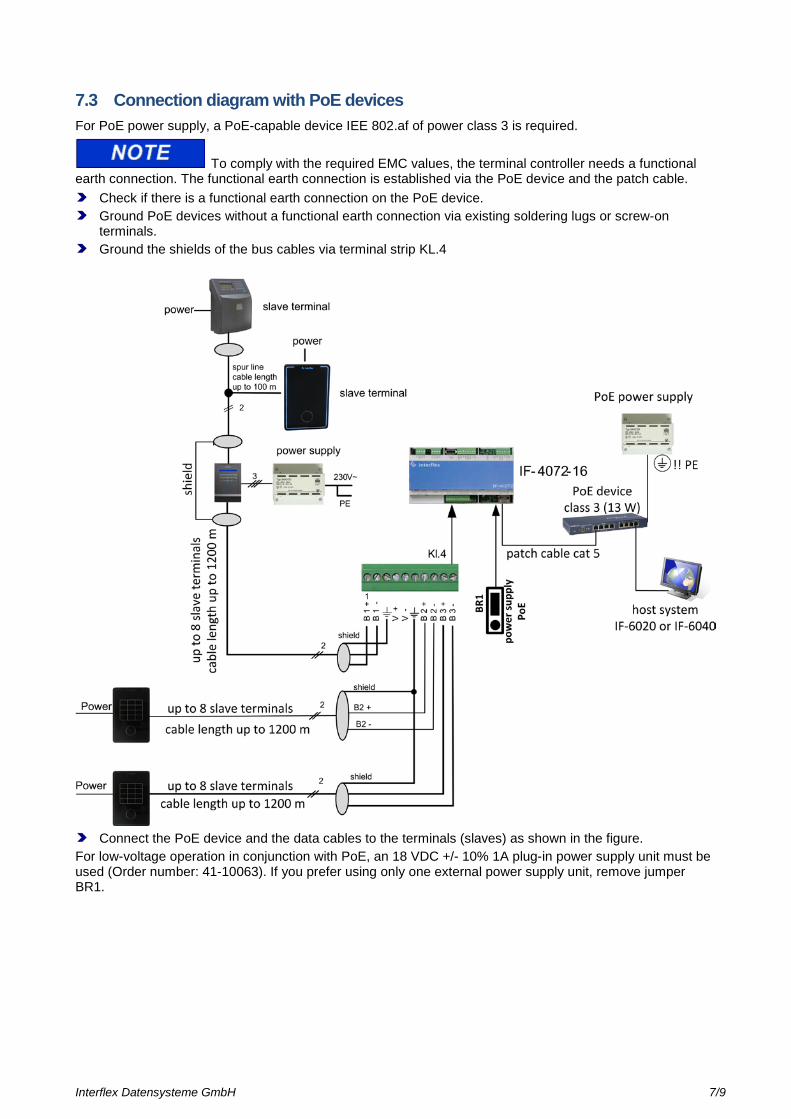
7.3 Connection diagram with PoE devices For PoE power supply, a PoE-capable device IEE 802.af of power class 3 is required.
To comply with the required EMC values, the terminal controller needs a functional earth connection. The functional earth connection is established via the PoE device and the patch cable.
Check if there is a functional earth connection on the PoE device. Ground PoE devices without a functional earth connection via existing soldering lugs or screw-on
terminals. Ground the shields of the bus cables via terminal strip KL.4
Connect the PoE device and the data cables to the terminals (slaves) as shown in the figure.
For low-voltage operation in conjunction with PoE, an 18 VDC +/- 10% 1A plug-in power supply unit must be used (Order number: 41-10063). If you prefer using only one external power supply unit, remove jumper BR1.
Interflex Datensysteme GmbH 8/9
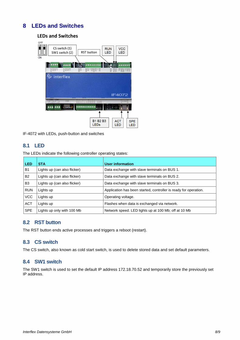
8 LEDs and Switches
IF-4072 with LEDs, push-button and switches
8.1 LED The LEDs indicate the following controller operating states:
LED STA User information B1 Lights up (can also flicker) Data exchange with slave terminals on BUS 1.
B2 Lights up (can also flicker) Data exchange with slave terminals on BUS 2.
B3 Lights up (can also flicker) Data exchange with slave terminals on BUS 3.
RUN Lights up Application has been started, controller is ready for operation.
VCC Lights up Operating voltage.
ACT Lights up Flashes when data is exchanged via network.
SPE Lights up only with 100 Mb Network speed. LED lights up at 100 Mb; off at 10 Mb
8.2 RST button The RST button ends active processes and triggers a reboot (restart).
8.3 CS switch The CS switch, also known as cold start switch, is used to delete stored data and set default parameters.
8.4 SW1 switch The SW1 switch is used to set the default IP address 172.18.70.52 and temporarily store the previously set IP address.
Interflex Datensysteme GmbH 9/9
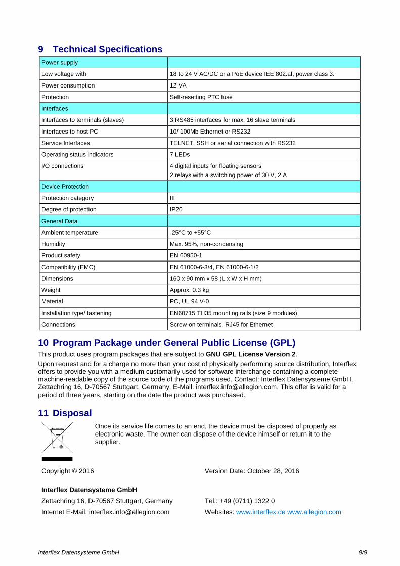
9 Technical Specifications Power supply
Low voltage with 18 to 24 V AC/DC or a PoE device IEE 802.af, power class 3.
Power consumption 12 VA
Protection Self-resetting PTC fuse
Interfaces
Interfaces to terminals (slaves) 3 RS485 interfaces for max. 16 slave terminals
Interfaces to host PC 10/ 100Mb Ethernet or RS232
Service Interfaces TELNET, SSH or serial connection with RS232
Operating status indicators 7 LEDs
I/O connections 4 digital inputs for floating sensors 2 relays with a switching power of 30 V, 2 A
Device Protection
Protection category III
Degree of protection IP20
General Data
Ambient temperature -25°C to +55°C
Humidity Max. 95%, non-condensing
Product safety EN 60950-1
Compatibility (EMC) EN 61000-6-3/4, EN 61000-6-1/2
Dimensions 160 x 90 mm x 58 (L x W x H mm)
Weight Approx. 0.3 kg
Material PC, UL 94 V-0
Installation type/ fastening EN60715 TH35 mounting rails (size 9 modules)
Connections Screw-on terminals, RJ45 for Ethernet
10 Program Package under General Public License (GPL) This product uses program packages that are subject to GNU GPL License Version 2. Upon request and for a charge no more than your cost of physically performing source distribution, Interflex offers to provide you with a medium customarily used for software interchange containing a complete machine-readable copy of the source code of the programs used. Contact: Interflex Datensysteme GmbH, Zettachring 16, D-70567 Stuttgart, Germany; E-Mail: [email protected]. This offer is valid for a period of three years, starting on the date the product was purchased.
11 Disposal
Once its service life comes to an end, the device must be disposed of properly as electronic waste. The owner can dispose of the device himself or return it to the supplier.
Copyright © 2016 Version Date: October 28, 2016
Interflex Datensysteme GmbH Zettachring 16, D-70567 Stuttgart, Germany Tel.: +49 (0711) 1322 0 Internet E-Mail: [email protected] Websites: www.interflex.de www.allegion.com