Embed Size (px)
Citation preview

1
INSTALLATION OF IN-PAVEMENT LIGHTS IN CONCRETE PAVEMENT
& IMPACT ON LIGHT PHOTOMETRICS
Ornulv (Arnie) Sonsteby, PE&
Doron Lean
Penn State / FAA Airport Conference 2007
2
IPRF-03-1 Project
Estimated Completion: 2007PI & Contact: Ornulv (Arnie) Sonsteby, P.E.email: [email protected]
Best Practices Guide forIn-Pavement Lighting, PCC Pavement
Sponsored by: FAA, in Cooperative Agreement with
Innovative Pavement Research Foundation (IPRF)
3
GUIDE CONTENT
Coordination between disciplines
Installation in new vs. existing PCC
Products, methods, tolerances
Boxouts / blockouts
Deficiencies and corrective alternatives
Strength and load transfer
4
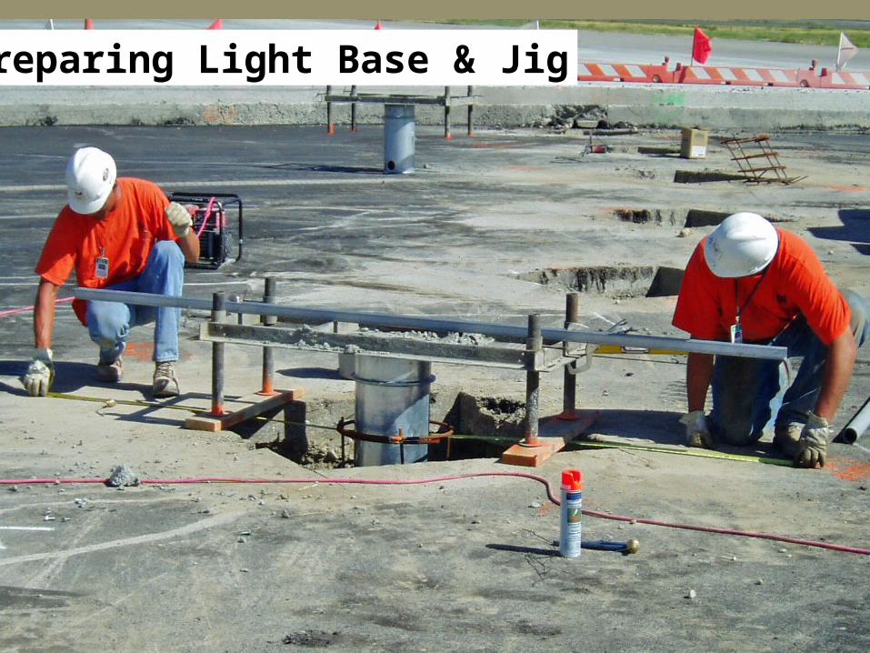
Preparing Light Base & Jig

5
Light Base Installation
(a) “Anchor” function (preparation for paving)
(b) “Strengthening” function (completed installation)
Finish Grade
Bearing Strength
VerticalStrength
Tie toPCC Slab Shear
Strength
Finish Grade
Light Base
Rebar Cage
BaseLayer
(b)(a)
6
INSTALLATION ISSUES
Coordination between disciplines
Selecting:
Methods & procedures
lighting products Pavement materials
Tolerances & verification
7
CCOORDINATION IN DESIGN
Light location vs. pavement joints
Materials and method
QC/QA
Tolerances and Consequences
8
PCC JOINT CONFLICTS
Touch Down Zone Lights
Lead-off / Lead-on TW CTL Lights
TW CTL Lights at curves / intersections
In-pavement RGL / Stop Bar Lights
9
MATERIALS & METHODS
Light Base, Conduit, Pavement materials
Installation procedures and “structure” -- in new or existing pavement
Surface finish (“cookie cutter” vs. Core)
10
QC / QA
The quality of installation depends on:
Good design by engineer
Good craftsmanship by installer
Close coordination between disciplines
Inspection / verification of compliance
11
Tolerances and Consequences
Pavement vs. Base tolerances
Light Base: Location, Height, Azimuth, Level
When to modify, when to replace
12
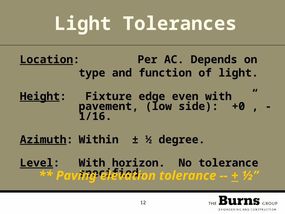
Location:Per AC. Depends on type and function of light.
Height: Fixture edge even with pavement, (low side): +0”, -1/16.
Azimuth: Within ± ½ degree.
Level: With horizon. No tolerance specified.
Light Tolerances
** Paving elevation tolerance -- + ½”
13
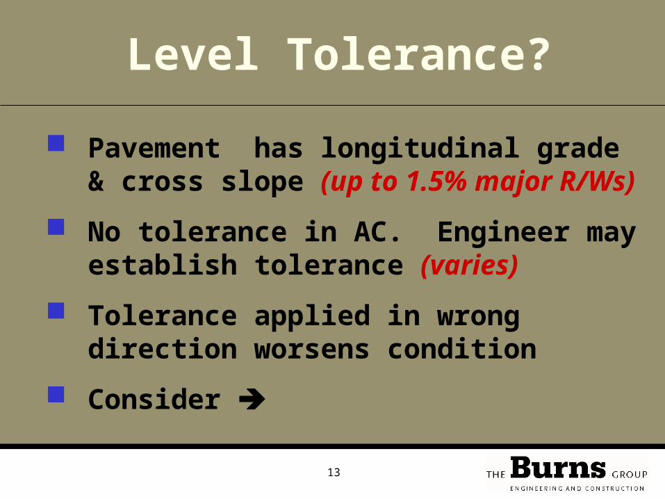
Level Tolerance?
Pavement has longitudinal grade & cross slope (up to 1.5% major R/Ws)
No tolerance in AC. Engineer may establish tolerance (varies)
Tolerance applied in wrong direction worsens condition
Consider
14
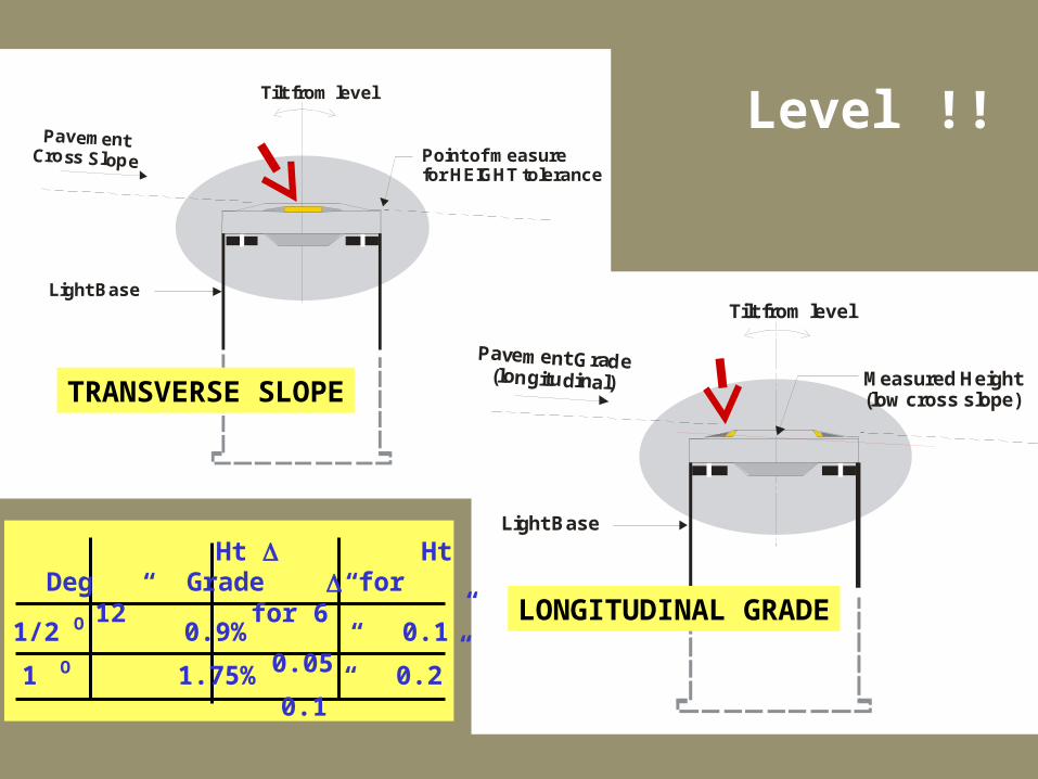
PavementCross Slope Point of measure
for HEIGHT tolerance
Light Base
Tilt from level
Pavement Grade(longitudinal) Measured Height
(low cross slope)
Light Base
Tilt from level
Level !!
TRANSVERSE SLOPE
LONGITUDINAL GRADEDeg Grade for 12”
for 6”
Ht Ht
1/2 0.9% 0.1” 0.05” 1 1.75% 0.2” 0.1”
O
O
15
COORDINATION IN CONSTRUCTION
Survey
Materials and method
QC/QA
Tolerances and Consequences
16
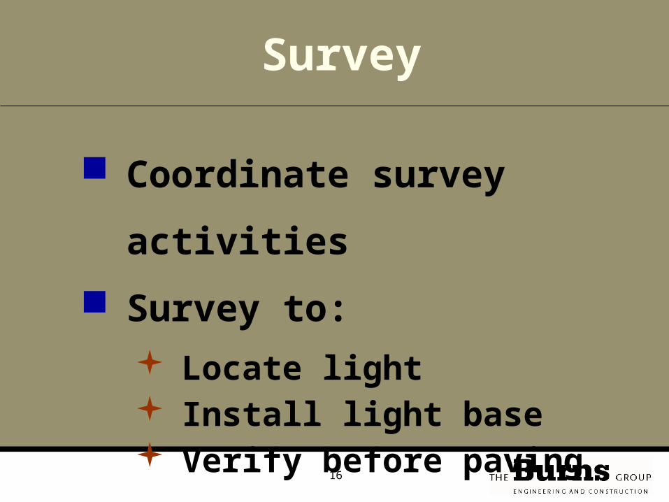
Coordinate survey
activities
Survey to: Locate light Install light base Verify before paving
Survey
17
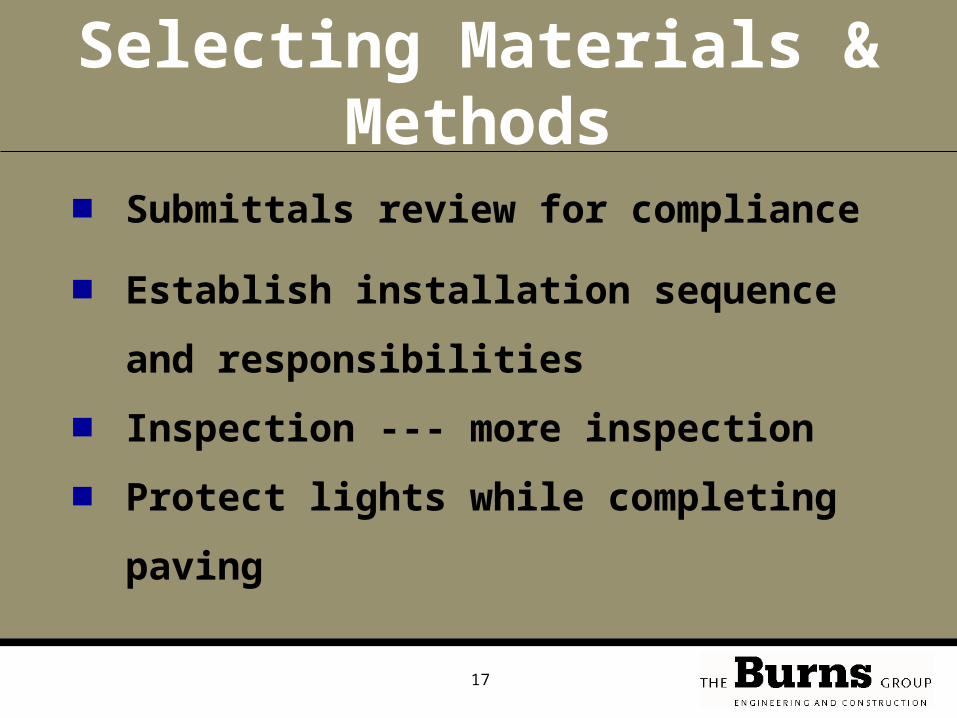
Selecting Materials & Methods
■ Submittals review for compliance
■ Establish installation sequence and
responsibilities
■ Inspection --- more inspection
■ Protect lights while completing paving

18Setting base “in space”
Conduit in pavement base layer
Light base
19
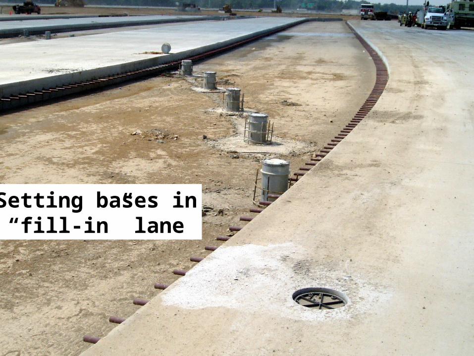
Setting bases in“fill-in” lane
20
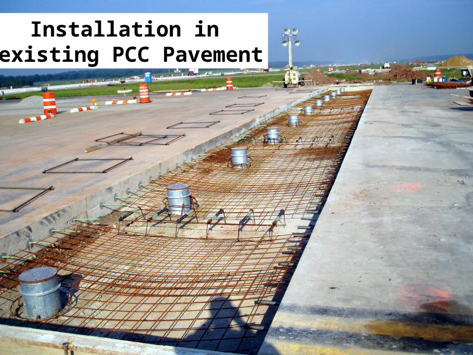
RW Edge Light, Toe-InInstallation in existing PCC Pavement
21
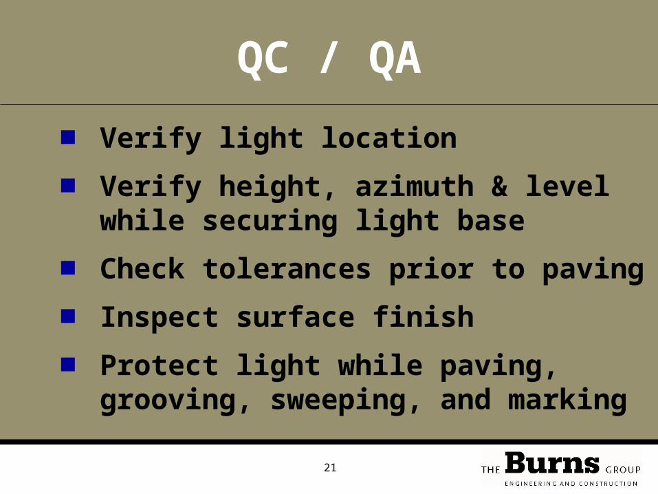
QC / QA
■ Verify light location
■ Verify height, azimuth & level while securing light base
■ Check tolerances prior to paving
■ Inspect surface finish
■ Protect light while paving, grooving, sweeping, and marking
22
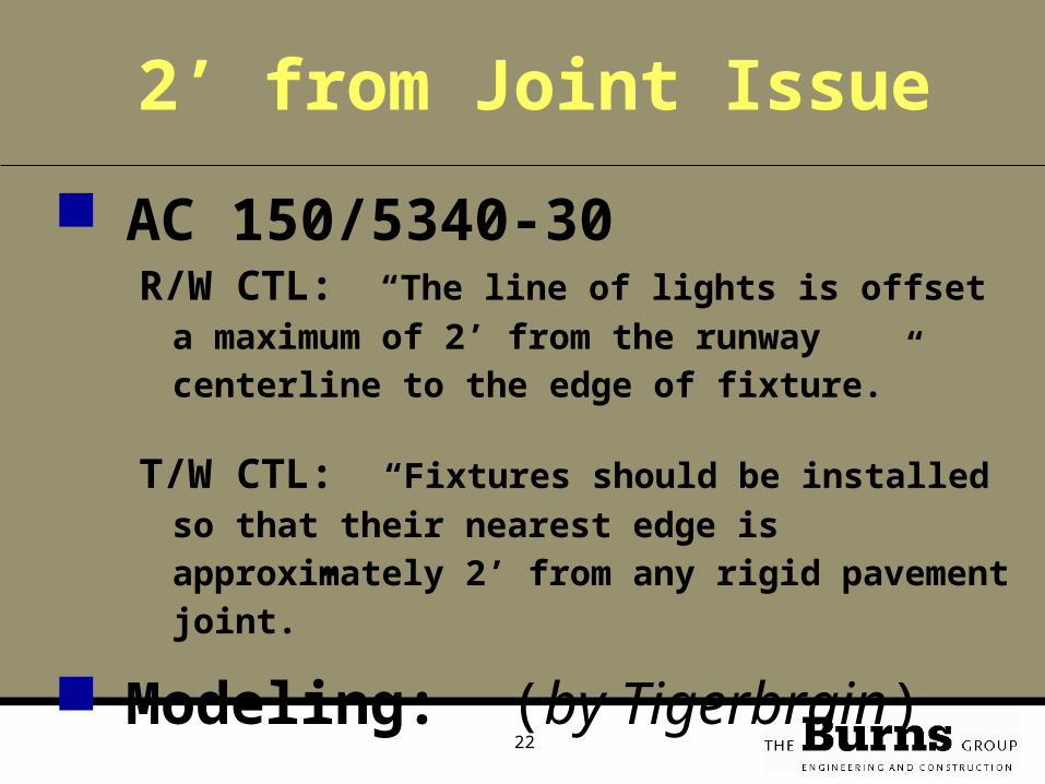
AC 150/5340-30R/W CTL: “The line of lights is offset a
maximum of 2’ from the runway centerline to the edge of fixture.”
T/W CTL: “Fixtures should be installed so that their nearest edge is approximately 2’ from any rigid pavement joint.”
Modeling: (by Tigerbrain)
2’ from Joint Issue
23
0
5
10
15
20
0 5 10 15 20
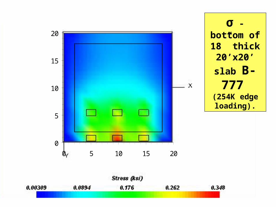
σ - bottom of 18” thick20’x20’
slab B-777
(254K edge loading).
24
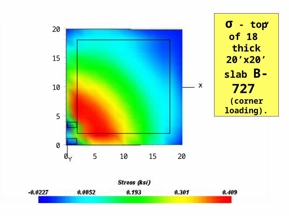
0
5
10
15
20
0 5 10 15 20
σ - top of 18” thick20’x20’
slab B-727 (corner
loading).
25
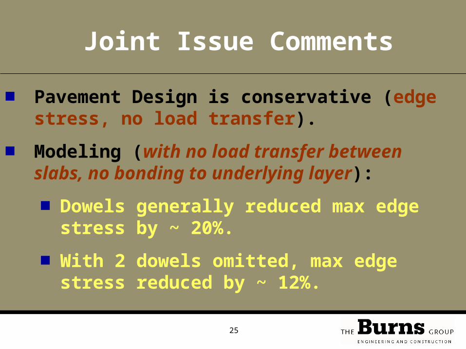
Joint Issue Comments
■ Pavement Design is conservative (edge stress, no load transfer).
■ Modeling (with no load transfer between slabs, no bonding to underlying layer):
■ Dowels generally reduced max edge stress by ~ 20%.
■ With 2 dowels omitted, max edge stress reduced by ~ 12%.

26
(Joint Issue Comments continued)
■ Hence: Inside 2’, with 1 or 2 dowels omitted has minimal impact on slab-slab load transfer.
■ Load transfer between light base and pavement – assessment suggests non-issue.
■ Embedded steel can help control cracking close to joint.
■ Alternative: Boxout
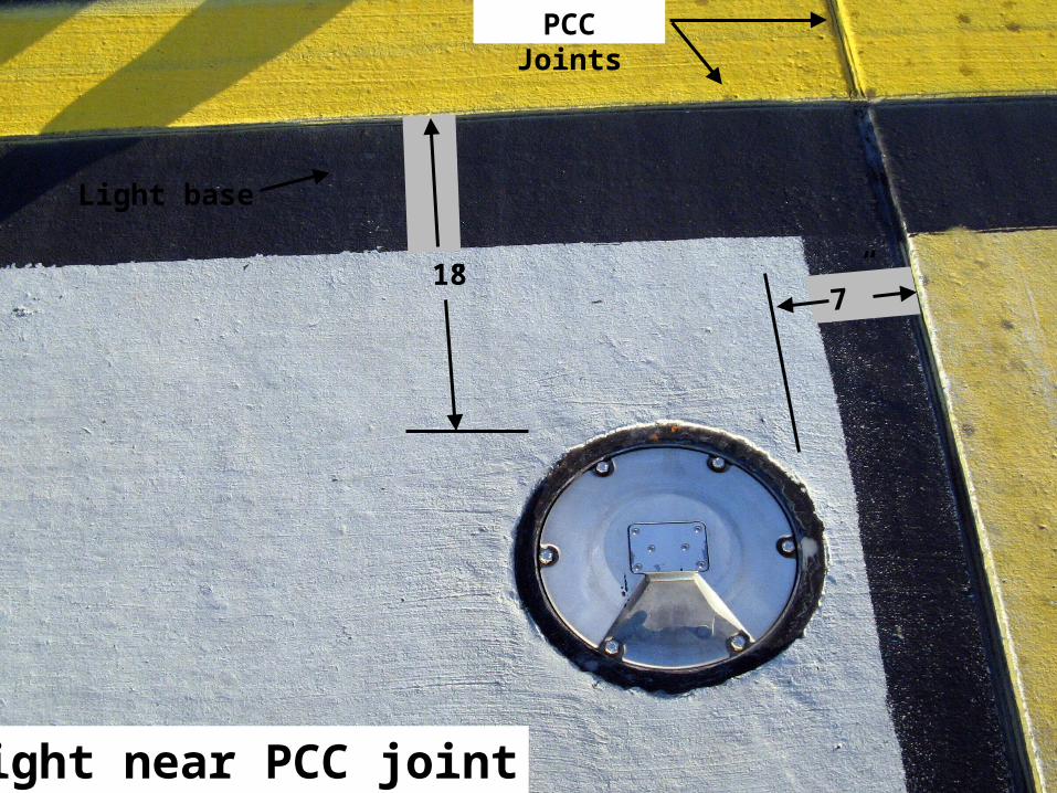
27Light near PCC joint
PCC Joints
Light base
18” 7”
28
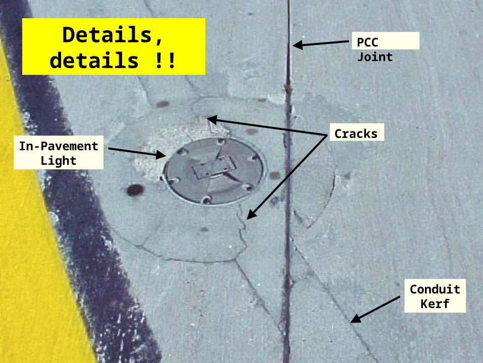
Cracks
Conduit Kerf
PCC Joint
In-Pavement Light
Details, details !!
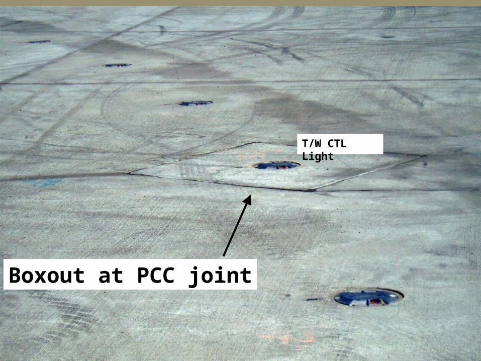
29
Boxout at PCC joint
T/W CTL Light
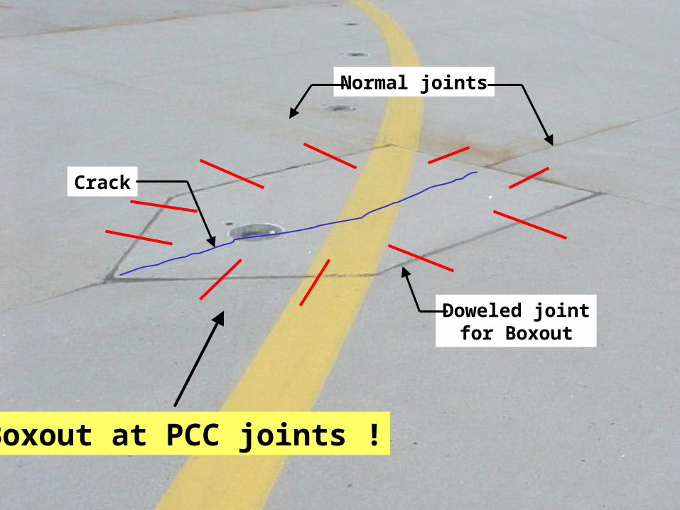
30
Normal joints
Doweled jointfor Boxout
Crack
Boxout at PCC joints !
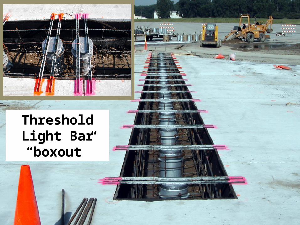
31
Threshold Light Bar“boxout”

32
A few Related
concerns

33
KERFS
S pall
Standard sawed jointcarried through kerf
PCC Pavement
Existing crack closes withwarm ing temperature
Pressure on fill materia lat crack or jo int
Maintain existing pavement joints - for full section of kerf !
PCC Joint
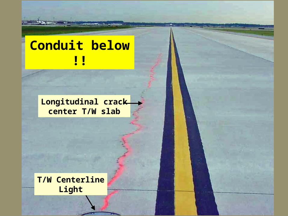
34
Longitudinal crackcenter T/W slab
T/W CenterlineLight
Conduit below !!
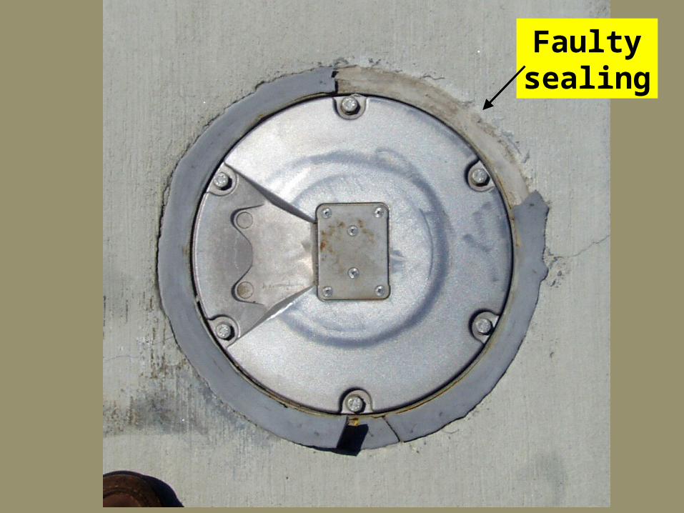
35
Faultysealing
36
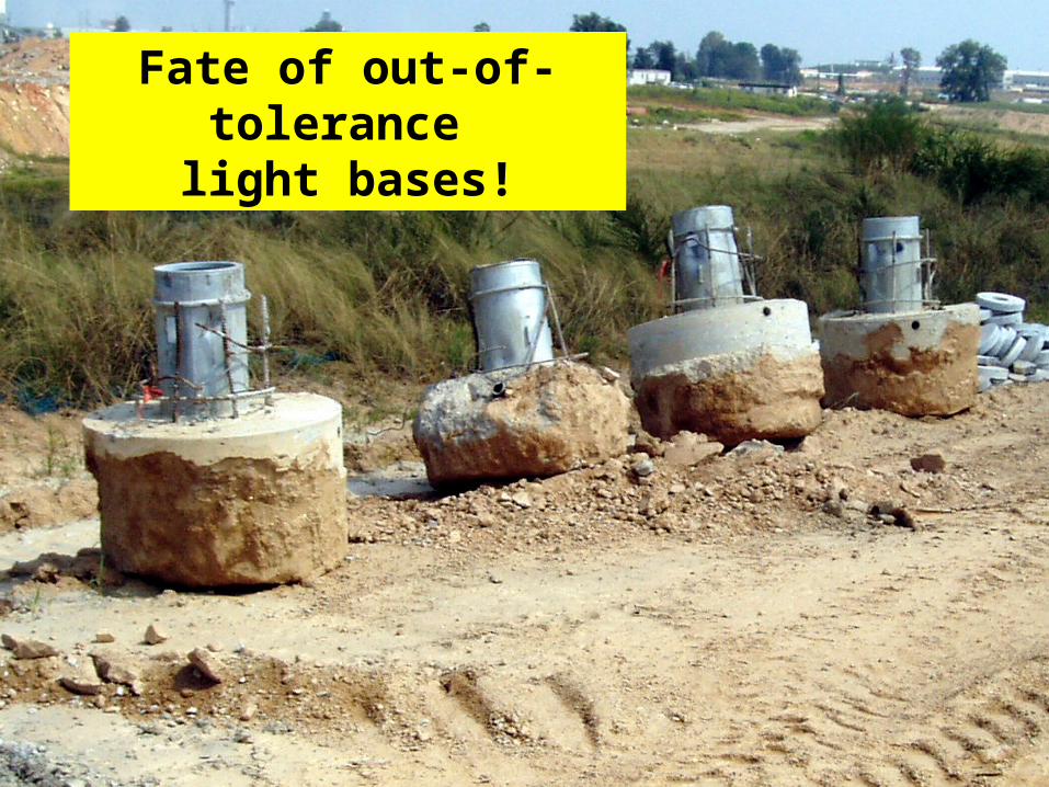
Fate of out-of-tolerance
light bases!
37
Doron