Embed Size (px)
Citation preview

1
Introduction to VHDL (Continued)
EE19D
2
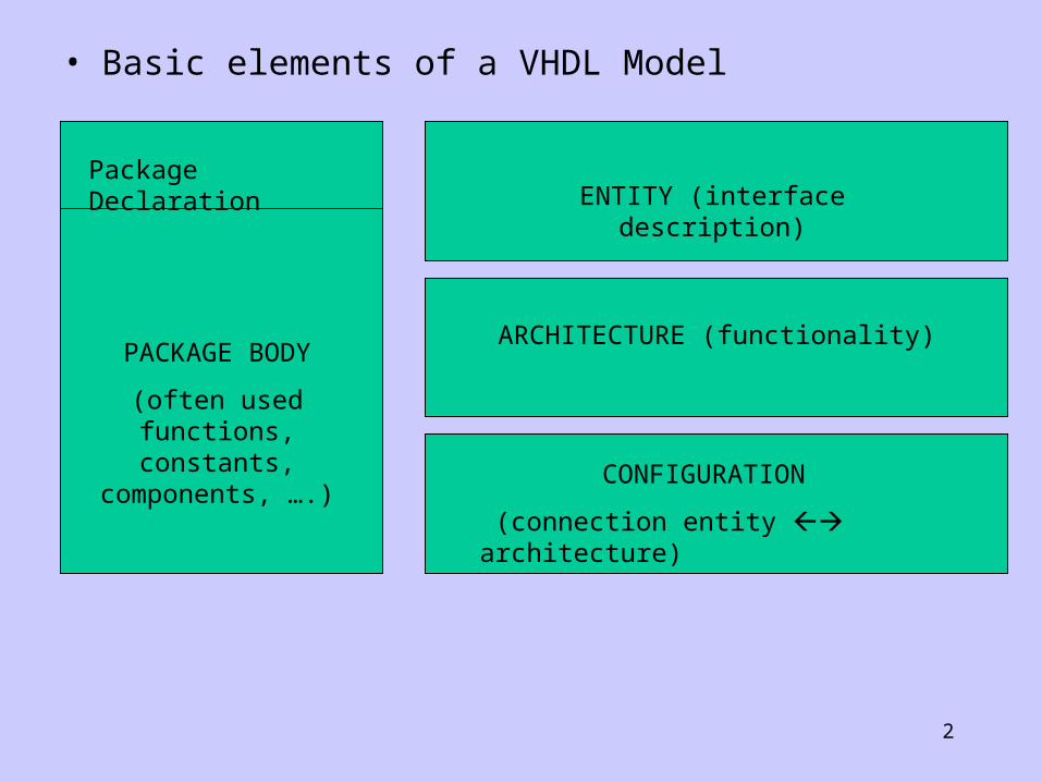
• Basic elements of a VHDL Model
Package DeclarationENTITY (interface description)
ARCHITECTURE (functionality)
CONFIGURATION
(connection entity architecture)
PACKAGE BODY
(often used functions, constants,
components, ….)
3
• Two concepts are often used in modeling digital circuits with VHDL:– The external view reflected in the entity declaration which represents
an interface description. The important part of this interface description consists of signals over which different modules communicate with one another.
– The internal view is described in the architecture body. The architecture can be expressed according to two major approaches:
• structural description which serves as a base for the hierarchical design,
• behavioral description (algorithm, sequential and concurrent).• Being able to investigate different architectural alternatives
permits the development of systems to be done in an efficient top-down manner.
• If the architecture body consists of a structural description, the binding of architectures and entities of the instantiated submodules, the so-called components is done using configuration statements.
• The package contains declarations of frequently used data types, components, functions, etc. It consists of a package declaration and a package body.

4
• Entity declaration
This correspond to the information given by the symbols in traditional methods based on drawing schematics
Full Addercarry
sumA
B
Cin
Figure: Interface of a full-adder module
Signals which are used for communication with the surrounding modules are called ports.

5
• Example of entity
Entity fulladder
-- (after a double minus sign (-) the rest of the line is treated as a comment)
--
-- Interface description of FULLADDER
Port (A, B, Cin: in bit;
Sum, Carry: out bit);
End fulladder;
-This module has five ports. A port is used for interface purpose. It is characterized by its direction (mode) and the type of data it carries.
-We can identify three different modes: in (read only), out (write only), and buffer (read and write)
- The type can be: a bit, bit-vector, integer, etc…
-Syntax:: entity entity_name is
[generics]
[ports]
[declarations (types, constants, signals)
[definitions (functions, procedures)]
[begin -- normally not used
statements]
End [entity_name];

6
Architecture
• The internal body of digital system is described by its architecture.
• Syntax: architecture architecture_name of entity_name is
[arch_declarative_part] begin [arch_statement_part] end [architecture_name];
• Models of description– Structural description (connection of different
components)– Behavioral description (algorithmic or testbench,
concurrent, and sequential)

7
Fig. Hierarchical Circuit Design
All the modeling styles share the same organization of the architecture.
Syntax: architecture architecture_name of entity_name
[arch_declarative_part]
begin
[architecture_part]
end [architecture_name];
keywords

8
Architecture: Concurrent Behavioral Description• This kind of description specifies a dataflow through the entity
based on concurrent signal assignment statements.• Example 1:
architecture Concurrent of fulladder is begin sum <= A xor B xor Cin after 5 ns;
Carry <= (A and B) or (B and Cin) or (A and Cin) after 3 ns
end concurrent;• The symbol <= indicates the signal assignment. • A concurrent signal assignment is executed whenever the value of a
signal in the expression on the right side changes.• Some concurrent statements are listed below:a) concurrent signal assignment
– Syntax: [label:] signal_name <= [transport] expression [after time_expr] {,
expression [after time_expr]};* The keyword transport affects the handling of multiple signal events coming
in short time one after another.
b) conditional signal assignment statement: different assignments are possible to one target signal. The choice of a particular assignment is done using if – elsif – else structure.- Syntax: [label:]
signal_name <= expression when condition else { expression when condition else}expression;
9
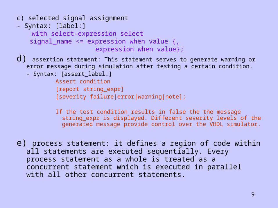
c) selected signal assignment- Syntax: [label:]
with select-expression select signal_name <= expression when value {,
expression when value};
d) assertion statement: This statement serves to generate warning or error message during simulation after testing a certain condition.- Syntax: [assert_label:]
Assert condition[report string_expr][severity failure|error|warning|note];
If the test condition results in false the the message string_expr is displayed. Different severity levels of the generated message provide control over the VHDL simulator.
e) process statement: it defines a region of code within all statements are executed sequentially. Every process statement as a whole is treated as a concurrent statement which is executed in parallel with all other concurrent statements.
10
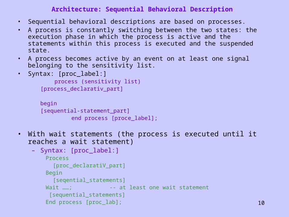
Architecture: Sequential Behavioral Description
• Sequential behavioral descriptions are based on processes. • A process is constantly switching between the two states: the execution
phase in which the process is active and the statements within this process is executed and the suspended state.
• A process becomes active by an event on at least one signal belonging to the sensitivity list.
• Syntax: [proc_label:] process (sensitivity list)
[process_declarativ_part]
begin [sequential-statement_part]
end process [proce_label];
• With wait statements (the process is executed until it reaches a wait statement)– Syntax: [proc_label:]
Process[proc_declaratiV_part]
Begin[seqential_statements]
Wait ……; -- at least one wait statement [sequential_statements]End process [proc_lab];
11
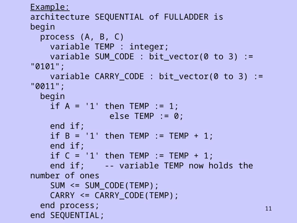
Example: architecture SEQUENTIAL of FULLADDER is begin process (A, B, C) variable TEMP : integer; variable SUM_CODE : bit_vector(0 to 3) := "0101"; variable CARRY_CODE : bit_vector(0 to 3) := "0011"; begin if A = '1' then TEMP := 1; else TEMP := 0; end if; if B = '1' then TEMP := TEMP + 1; end if; if C = '1' then TEMP := TEMP + 1; end if; -- variable TEMP now holds the number of ones SUM <= SUM_CODE(TEMP); CARRY <= CARRY_CODE(TEMP); end process; end SEQUENTIAL;
12
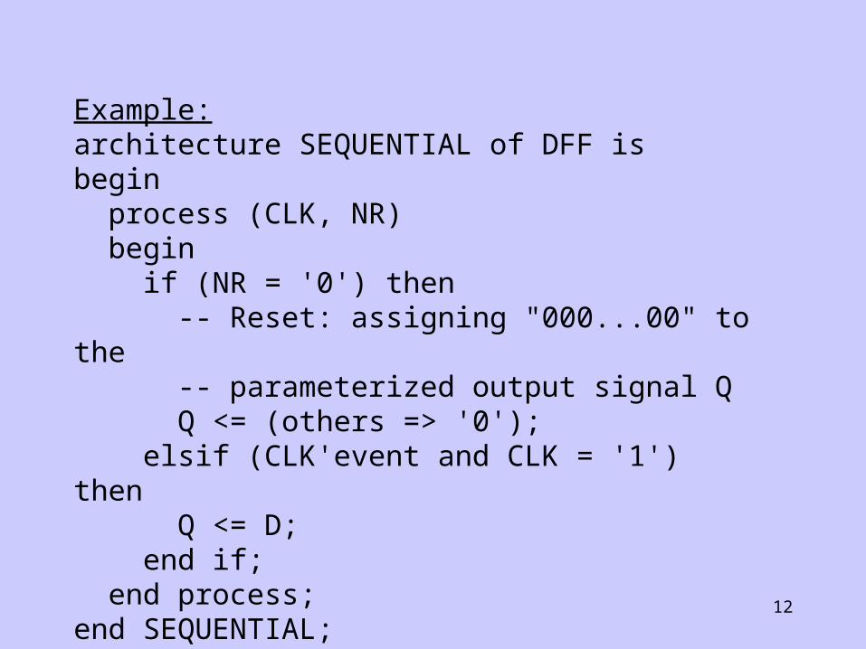
Example: architecture SEQUENTIAL of DFF is begin process (CLK, NR) begin if (NR = '0') then -- Reset: assigning "000...00" to the -- parameterized output signal Q Q <= (others => '0'); elsif (CLK'event and CLK = '1') then Q <= D; end if; end process; end SEQUENTIAL;

13
STRUCTURAL DESCRIPTION: Case of the fulladder
1-bit Full Adder
OR
(2)
Half Adder

14
A
B
Cin
I1
I2
S
C
I1
I2
S
C X
Y
o
Sum
CarryC1
C2S1
15
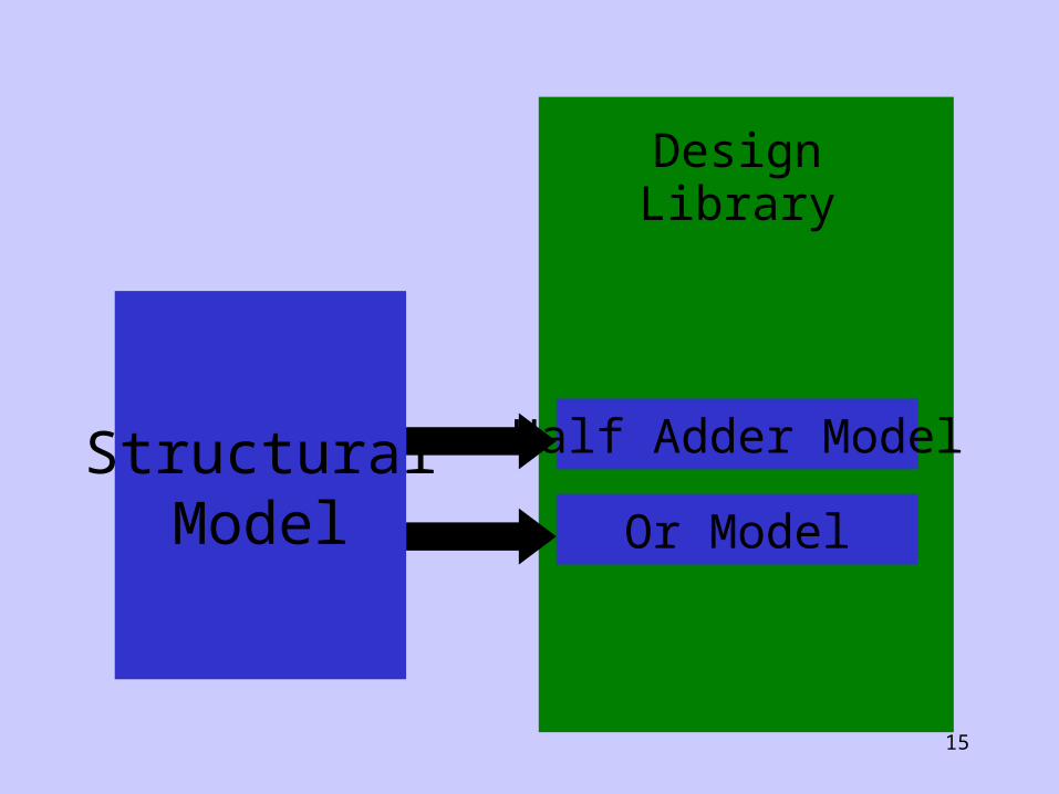
StructuralModel
DesignLibrary
Half Adder Model
Or Model
16
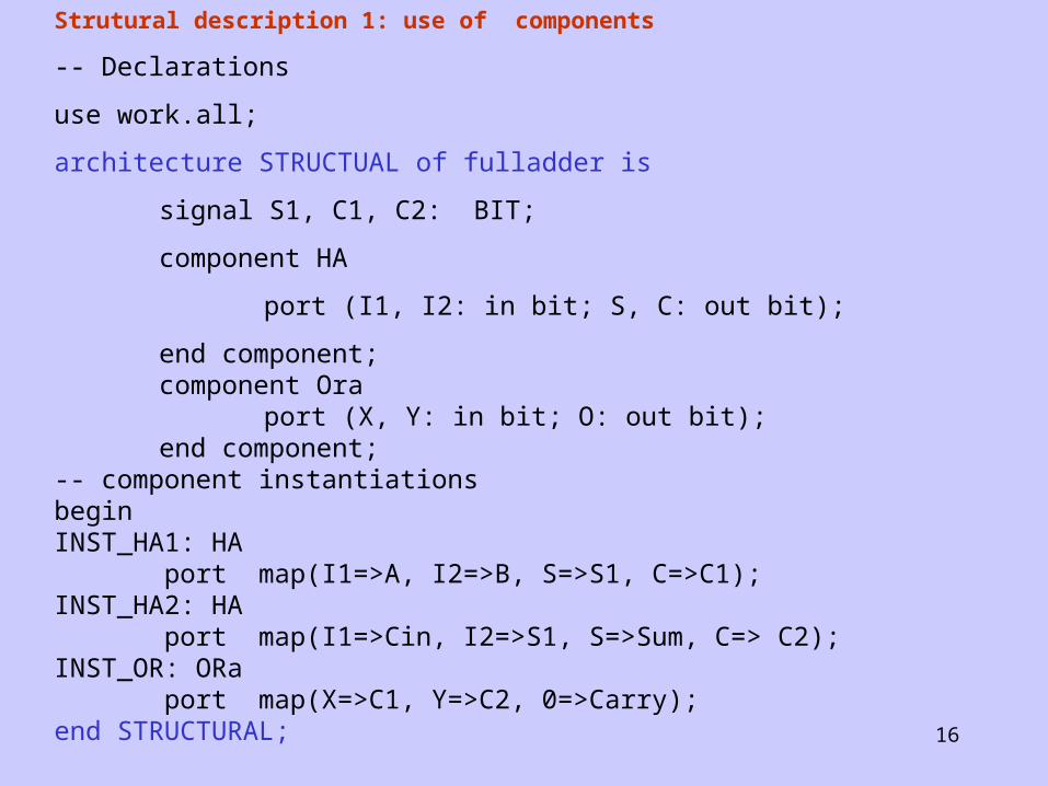
Strutural description 1: use of components
-- Declarations
use work.all;
architecture STRUCTUAL of fulladder is
signal S1, C1, C2: BIT;
component HA
port (I1, I2: in bit; S, C: out bit);
end component;component Ora
port (X, Y: in bit; O: out bit);end component;
-- component instantiationsbeginINST_HA1: HA port map(I1=>A, I2=>B, S=>S1, C=>C1);INST_HA2: HA port map(I1=>Cin, I2=>S1, S=>Sum, C=> C2);INST_OR: ORa port map(X=>C1, Y=>C2, 0=>Carry);end STRUCTURAL;
17
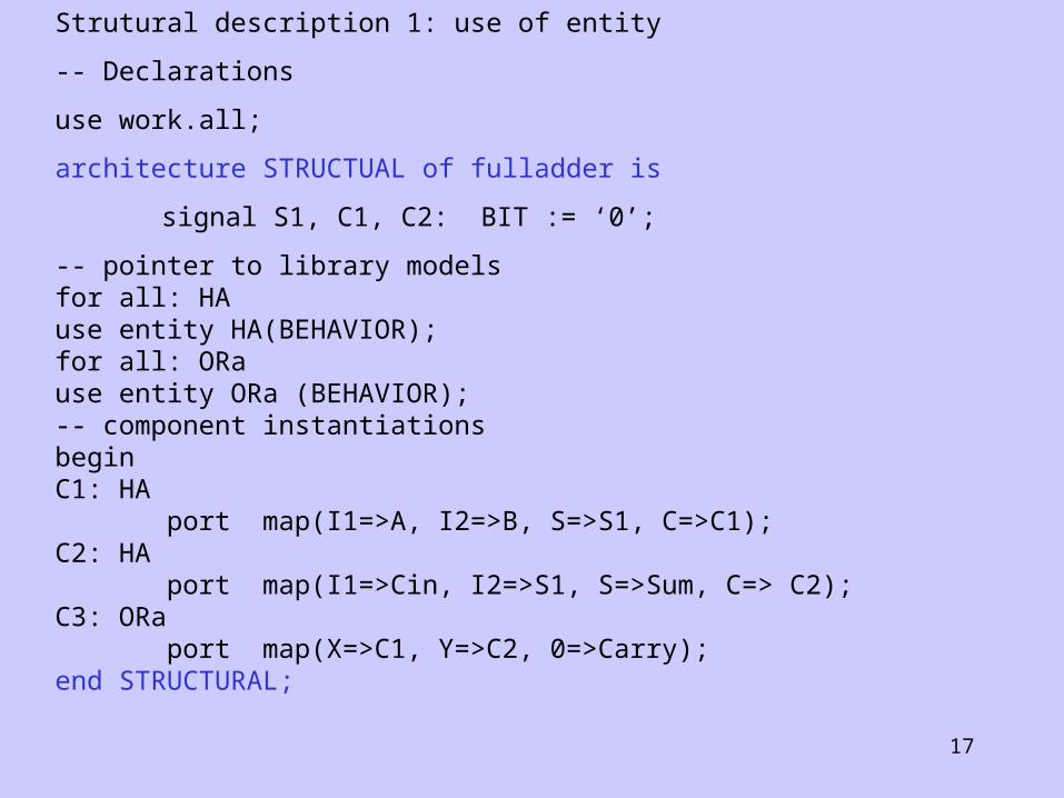
Strutural description 1: use of entity
-- Declarations
use work.all;
architecture STRUCTUAL of fulladder is
signal S1, C1, C2: BIT := ‘0’;
-- pointer to library modelsfor all: HAuse entity HA(BEHAVIOR);for all: ORause entity ORa (BEHAVIOR);-- component instantiationsbeginC1: HA port map(I1=>A, I2=>B, S=>S1, C=>C1);C2: HA port map(I1=>Cin, I2=>S1, S=>Sum, C=> C2);C3: ORa port map(X=>C1, Y=>C2, 0=>Carry);end STRUCTURAL;
18
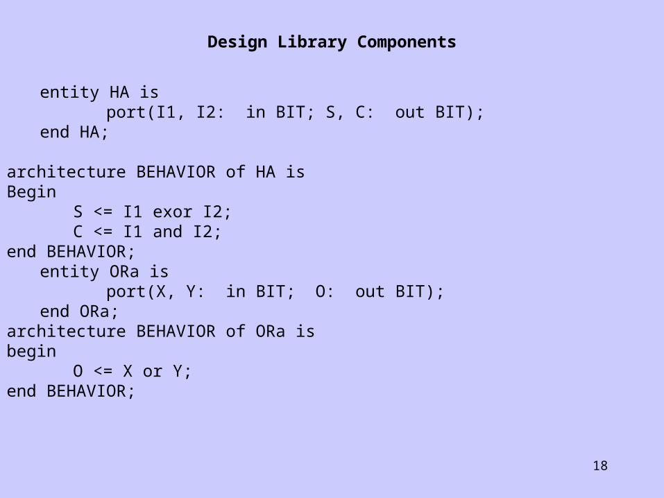
Design Library Components
entity HA isport(I1, I2: in BIT; S, C: out BIT);
end HA;
architecture BEHAVIOR of HA is Begin
S <= I1 exor I2;C <= I1 and I2;
end BEHAVIOR;entity ORa is
port(X, Y: in BIT; O: out BIT);end ORa;
architecture BEHAVIOR of ORa is begin
O <= X or Y;end BEHAVIOR;
19
Configuration
• The concept of configuration in VHDL allows an entity to have multiple associated architectures.
• The role of the configuration is to define a unique system description from the various design units.
• Configuration Specifications - specify the bindings between a component instance in a structural architecture and a library model.
• Configuration specifications can be in the structural architecture itself or in a configuration declaration.
• Configuration Declaration (Body) - A separate analyzable entity which holds all the component bindings for a structural architecture.
20
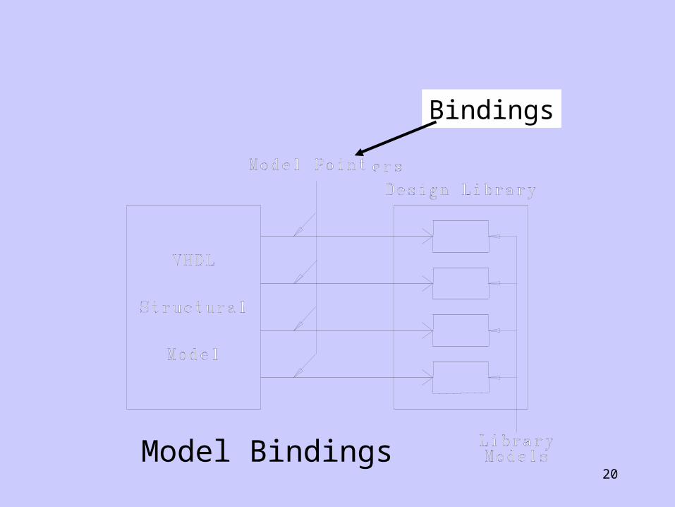
Bindings
Model Bindings
21
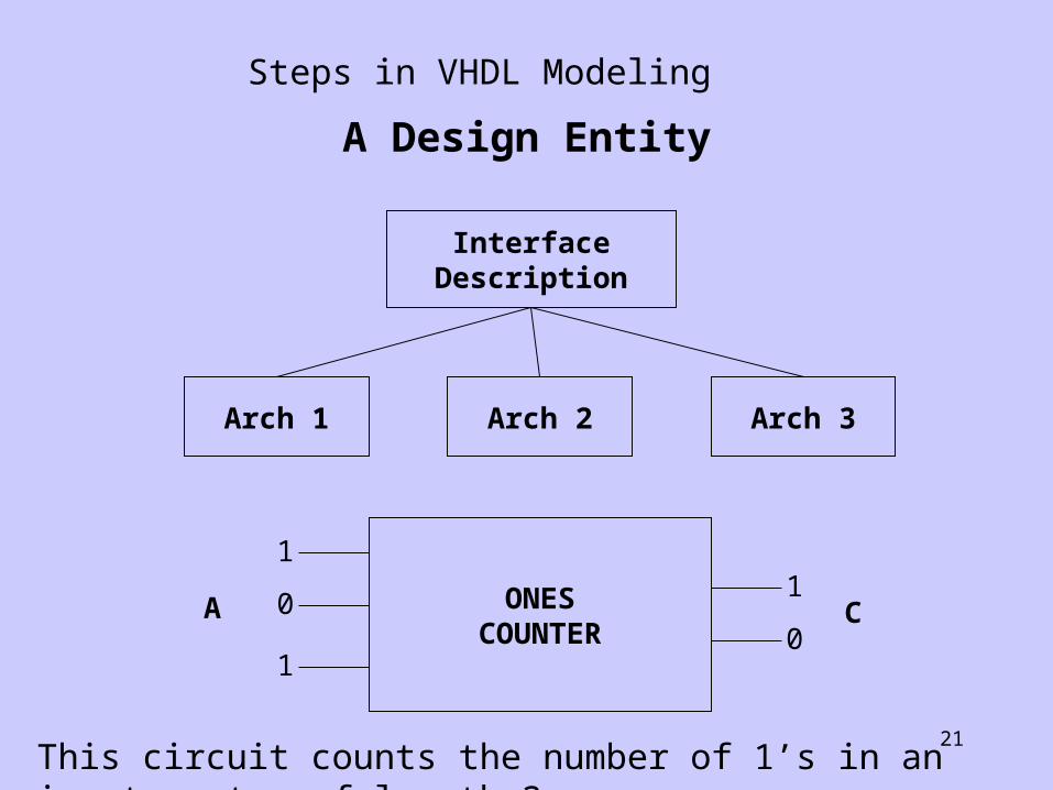
A Design Entity
InterfaceDescription
Arch 1 Arch 2 Arch 3
ONESCOUNTER
1
0
1
1
0CA
Steps in VHDL Modeling
This circuit counts the number of 1’s in an input vector of length 3
22
entity ONES_CNT isport (A: in BIT_VECTOR(2 downto 0);
C: out BIT_VECTOR(1 downto 0));
------ Truth Table:-----------------------------------
---|A2 A1 A0 | C1 C0 |---------------------------------- |0 0 0 | 0 0 |-- |0 0 1 | 0 1 |-- |0 1 0 | 0 1 |-- |0 1 1 | 1 0 |-- |1 0 0 | 0 1 |-- |1 0 1 | 1 0 |-- |1 1 0 | 1 0 |-- |1 1 1 | 1 1 |-----------------------------------end ONES_CNT;
1 1
2 2
23
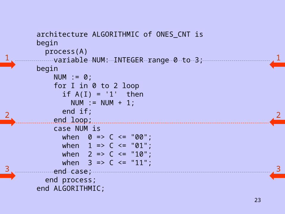
architecture ALGORITHMIC of ONES_CNT isbegin process(A) variable NUM: INTEGER range 0 to 3;begin NUM := 0; for I in 0 to 2 loop if A(I) = '1' then NUM := NUM + 1; end if; end loop; case NUM is when 0 => C <= "00"; when 1 => C <= "01"; when 2 => C <= "10"; when 3 => C <= "11"; end case; end process;end ALGORITHMIC;
1 1
2 2
3 3

24
Kmap DesignTruth Table:
-----------------------------------
|A2 A1 A0 | C1 C0 |--------------------------------|0 0 0 | 0 0 ||0 0 1 | 0 1 ||0 1 0 | 0 1 ||0 1 1 | 1 0 ||1 0 0 | 0 1 ||1 0 1 | 1 0 ||1 1 0 | 1 0 ||1 1 1 | 1 1 |
-----------------------------------

25
A1 A0
A2 | 00 01 11 10 |
0 1
1 1 1 1
C1
A1 A0
A2 | 00 01 11 10 |
0 1 1
1 1 1
C0
K - Maps for the Ones Counter
C1 = A1A0 + A2A0 + A2A1
C0 = A2A1’A0’ + A2’A1’A0 + A2A1A0 + A2’A1A0’

26
architecture DATA_FLOW of ONES_CNT is begin C(1) <= (A(1) and A(0)) or (A(2) and A(0)) or (A(2) and A(1)); C(0) <= (A(2) and not A(1) and not A(0)) or (not A(2) and not A(1)and A(0)) or (A(2) and A(1) and A(0)) or (not A(2) and A(1) and not A(0)); end DATA_FLOW;
1 1
2 2

27
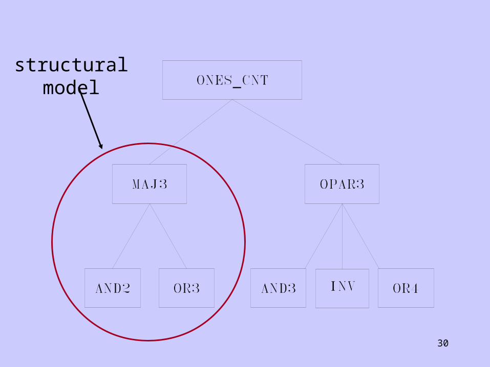
architecture MACRO of ONES_CNT is
begin
C(1) <= MAJ3(A);
C(0) <= OPAR3(A);
end MACRO;Must be previously declared
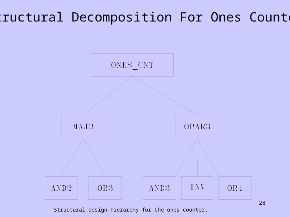
28Structural design hierarchy for the ones counter.
Structural Decomposition For Ones Counter
29
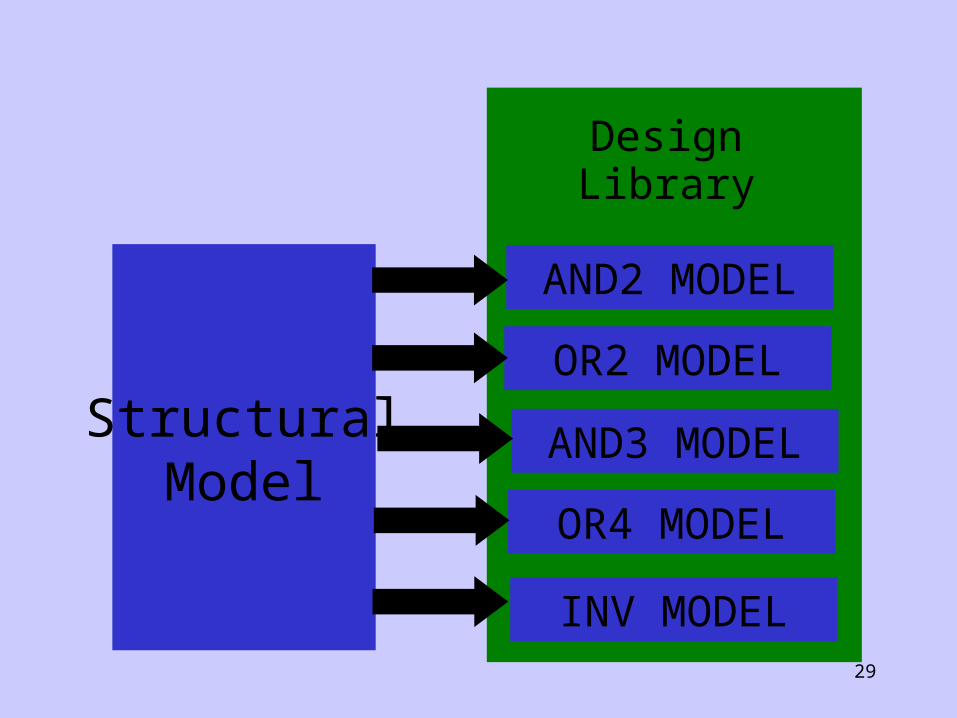
StructuralModel
DesignLibrary
AND2 MODEL
OR2 MODEL
AND3 MODEL
OR4 MODEL
INV MODEL
30
structural model
31
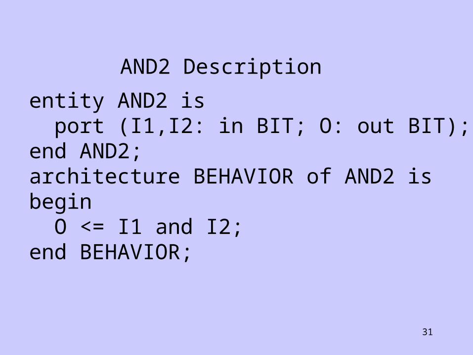
entity AND2 is port (I1,I2: in BIT; O: out BIT);end AND2;architecture BEHAVIOR of AND2 isbegin O <= I1 and I2;end BEHAVIOR;
AND2 Description

32
entity OR3 is port (I1,I2,I3:in BIT; O: out BIT);end OR3;architecture BEHAVIOR of OR3 isbegin O <= I1 or I2 or I3;end BEHAVIOR;
OR3 Description
33
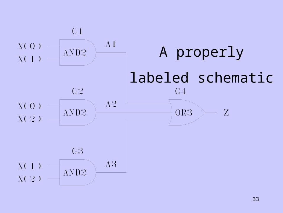
A properly
labeled schematic
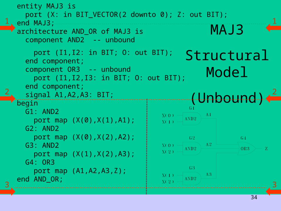
34
entity MAJ3 is port (X: in BIT_VECTOR(2 downto 0); Z: out BIT);end MAJ3;architecture AND_OR of MAJ3 is component AND2 -- unbound
port (I1,I2: in BIT; O: out BIT); end component; component OR3 -- unbound port (I1,I2,I3: in BIT; O: out BIT); end component; signal A1,A2,A3: BIT;begin G1: AND2 port map (X(0),X(1),A1); G2: AND2 port map (X(0),X(2),A2); G3: AND2 port map (X(1),X(2),A3); G4: OR3 port map (A1,A2,A3,Z);end AND_OR;
MAJ3
Structural Model
(Unbound)
1 1
2 2
3 3
35
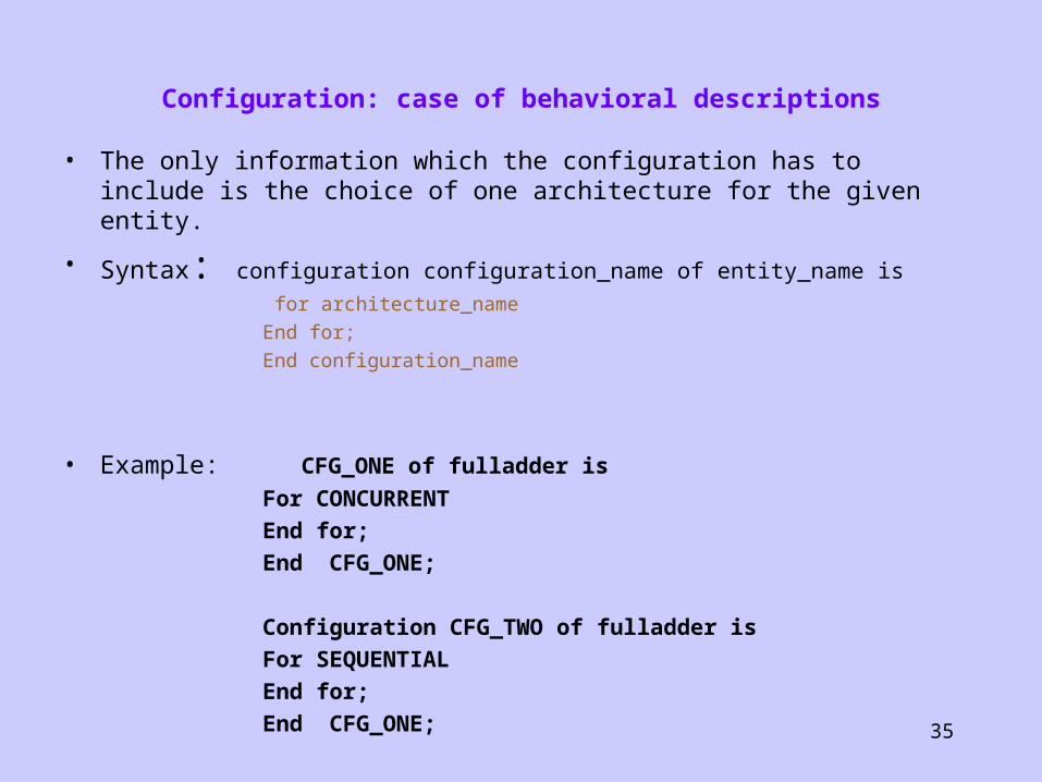
Configuration: case of behavioral descriptions
• The only information which the configuration has to include is the choice of one architecture for the given entity.
• Syntax: configuration configuration_name of entity_name is for architecture_nameEnd for;End configuration_name
• Example: confiCFG_ONE of fulladder is
For CONCURRENT End for;End CFG_ONE;
Configuration CFG_TWO of fulladder is For SEQUENTIALEnd for;End CFG_ONE;

36
Configuration: case of structural descriptions
If the configuration binds a structural description to an entity then further information about the instantiated components is required.
Due to the fact that the name of a component in the component declaration needs not be the same as the entity name of the instantiated component, their binding must be done by the configuration.
Furthermore, the binding of the component's entity and architecture must be established by the configuration
37
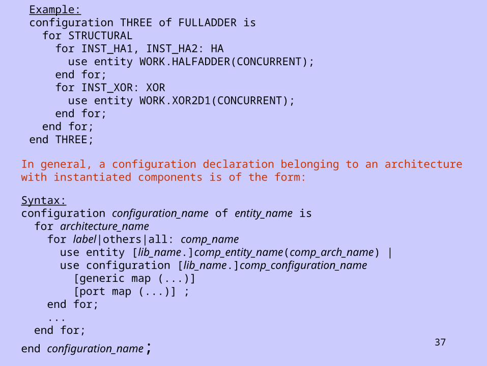
Example: configuration THREE of FULLADDER is for STRUCTURAL for INST_HA1, INST_HA2: HA use entity WORK.HALFADDER(CONCURRENT); end for; for INST_XOR: XOR use entity WORK.XOR2D1(CONCURRENT); end for; end for; end THREE;
In general, a configuration declaration belonging to an architecture with instantiated components is of the form:
Syntax: configuration configuration_name of entity_name is for architecture_name for label|others|all: comp_name use entity [lib_name.]comp_entity_name(comp_arch_name) | use configuration [lib_name.]comp_configuration_name [generic map (...)] [port map (...)] ; end for; ... end for;
end configuration_name;


![VHDL - Here is "PLDWorld.com"... · VHDL 설계 Functional ... entity_statement_part] end[entity_name]; entity example is ... with expression select target variable](https://img.pdfslide.net/doc/110x75/5af928527f8b9abd588c7e9b/vhdl-here-is-functional-entitystatementpart-endentityname-entity.jpg)


![VHDL03 chapter1.ppt [호환 모드] - dasan.sejong.ac.krdasan.sejong.ac.kr/~dihan/vhdl/VHDL03_chapter1.pdf · VHDL 프로그래밍 3. VHDL 설계단위 학습목표 Entity, Architecture의사용법알기](https://img.pdfslide.net/doc/110x75/5a9e3c3e7f8b9a6a218c84bc/vhdl03-dasansejongackrdasansejongackrdihanvhdlvhdl03chapter1pdfvhdl.jpg)