Embed Size (px)
Citation preview
CHAPTER. 1
1. INVITATION OF BUDGETARY OFFER
1.1. This invitation of the Budgetary offer for “DESIGN, MANUFACTURE, FABRICATION, SUPPLY, ERECTION, TESTING, COMMISSIONING AND HANDING OVER OF THE NEW FIRE FIGHTING FACILITIES INCLUDING PUMP HOUSE AND LAYING OF POWER
ELECTRICAL CABLE FROM EXISTING NEW PUMPHOUSE TO PROPOSED PUMP HOUSE FOR BHARATHI DOCK I & III AT CHENNAI PORT TRUST AND REMOVAL OF THE EXISTING FIRE FIGHTING SYSTEM AND TRANSPORT TO RSA YARD WITH OPERATION AND MAINTENANCE OF THE ENTIRE FIRE FIGHTING FACILITIES INCLUDING PUMP HOUSE FOR A PERIOD OF FIVE YEARS AT BD I& BDIII OF CHENNAI PORT TRUST ” as per the Trust specifications.
1.2. Budgetary offerers are advised to study the Budgetary offer Document including all the Schedules and Chapters carefully before submission of Budgetary offer. Submission of Budgetary offer shall be deemed to have been done after careful study and examination of Budgetary offer Document with full understanding of its implications After inspection and ascertaining site conditions. 1.3. Name of the Purchaser:
Chairman, Chennai Port Trust, Rajaji Salai, Chennai – 600 001.
1.4. Location – Bharathi Dock I & Bharathi Dock III of
Chennai Port Trust.
1.5. Addressee for Clarifications: Chief Mechanical Engineer, 7 th floor, Centenary building, Chennai Port Trust, Rajaji Salai, Chennai – 600 001. Phone: (044) 25362070, Fax: (044) 25360955.
(or) Dy.Chief Mechanical Engineer (R&D), 2 nd floor old administrative building, Chennai Port Trust, Rajaji Salai, Chennai – 600 001. Phone: (044) 25360628.
2
1.6. Date of Submission of Budgetary offer: On or before 10/10/2011. 1.7. Place of Submission of Budgetary offer:
Office of the Chief Mechanical Engineer, 7 th floor, Centenary building, Chennai Port Trust.
1.8. COMPLETION PERIOD: The completion period time is essence of this project. The entire project i.e., a) “Design, Manufacture, Fabrication, Supply, Erection, Testing, Commissioning and handing over of the new Fire Fighting Facilities including Construction of Pump House and laying of Power Electrical Cable from Existing New Pump house to proposed Pump House at Bharathi Dock I & III at Chennai Port Trust and removal of the existing Fire Fighting System and transport to RSA yard, shall be completed with in 21 months from the date of Approval of Drawing and b) Operation and Maintenance ( O & M ) of the new entire Fire Fighting Facilities including Pump House for a period of five years from completion and handing over of entire system to Chennai Port Trust” 1.9. PAYMENT TERMS for ( a ): Stage-I: 10% of the total cost shall be released after the approval and acceptance of the detailed design drawings and material list by IRS after submitting the equivalent value of Band Guarantee (BG). Stage-II: 40% of the total cost shall be released after receipt and inspection of entire materials by IRS surveyor and Trust Engineer as per the design drawings and material list at Trust work site after submitting the equivalent value of BG. Stage-III: 25% of the total cost shall be released after the completion of the erection works at site and after inspection and obtaining the receipt of report from IRS & Trust Engineers. Stage-IV: 25% of the total cost along with all Taxes and duties shall be released with in 30 days from the date of acceptance of Fire Fighting Facilities at BDI, BDIII after issue of certificate of acceptance by IRS and
Chief Mechanical Engineer and submitting the documentary proof of Taxes and duties & for other charges and all the BG for stage payments will be returned.

3
No escalation is permitted in this contract. 1.10. Payment Terms for O & M Period for ( b ) : During the O & M period the contractor shall submit the invoice along with service report on Half yearly basis for charges towards the operation and maintenance of Fire Fighting System. Payment against invoice shall be within 30 days from the date of receipt of invoice. 50% of the O & M Cost quoted for every year shall be paid once in six months after submission of satisfactory completion report from the Trust officials. 1.11 The offerer shall quote the rates as per the Bill of Quantities No 1 to 5 and consolidated rate as per the Cost Schedule I to IV
4
CHAPTER. 2
SCHEDULE ‘A’
2. TECHNICAL SPECIFICATION
2.1. SCOPE OF WORK: The work included in this budgetary offer for Design, Manufacture,
Fabrication, Supply, Erection, Testing, Commissioning and Handing over of Fire Fighting Facilities including construction of pump house and laying of Power Electrical Cable from existing new pump house to proposed Pump house at Bharathi Dock I and III, Removal of Existing Fire Fighting System
& Transportation to RSA yard and Operation & Maintenance of the entire Fire Fighting Facilities for a period of 5 (five) years at BDI &BDIII of Chennai Port Trust. The total system shall be designed as per OISD 156 / NFPA The specification describes certain broad requirements for guidance of the contractor. Everything may not be fully specified and there may be modifications required. This however, shall not relieve the contractor for not completing the work in every respect and or in accordance with the modern practice so that the fire fighting system will be completed and will satisfactorily carry out all the duties specified. The Budgetary offer shall quote for the complete system. The offer should contain full details of the system so quoted. The budgetary offerer may propose modifications if any to the specifications in a separate list supported by reasons and the Trust will examine the modification for its consent.
The materials to be used in the work shall be of the best quality to comply with the requirements explained in the specification and as per the appropriate Indian Standard Specifications specified in the list enclosed, and shall be suitably tropicalised and designed to withstand the saline water use and atmosphere at site.
The budgetary offerer may quote separately for any other items as extra which are not specifically brought to the schedule but which in his opinion are necessary for the proper enhancement in the fire protection system and its satisfactory operation.
2.2. Pumphouse and control tower:
The pump house and control tower building is considered as a separate unit from the approach jetty. The overall size of the building is 35m in east and western sides and 15m in north and southern sides. The ground
floor height is 7m. First floor and second floor height is 3m and 4m respectively. The ground floor with EOT crane facility shall be used for pump house facility as indicated by MEE Department and staircase shall be constructed to provide the access to the first floor and second floor and Top. The first floor and second floor shall be used for CISF Room and control tower respectively.
5
The substructure consists of friction cum end bearing piles,
longitudinal and cross beams connecting each pile at the top (at GF level). The columns are supported by the piles. The columns and beams at different floor level form the required framing system for the pump house and control tower. The column size is 750mm x 750mm. The beams sizes are given in the drawings. The pile diameter shall be of 1.2m. The founding level of the pile is – 30m. If required the founding level may be increased. The top level of the approach jetty is (+5.4m) and ground floor level of the pump house shall be of (+5.5m).
2.3. Approach from the Pump Room to Breakwater:
Total length of the approach structure from the existing Breakwater is 40m. 3Nos of cast in silt beam with slab of 500mm thick shall be provided from the existing Breakwater up to the length of 23m from the sea side edge of existing Breakwater as shown in the Drawing No.IIT/DOE/CHPT/001. This arrangement will form the part of the approach to the pump house. For this purpose the existing tetrapods protruding in the alignment of the approach to be removed to provide the required structure to support the beam.
The remaining length will be covered by the piled jetty with slab supported by beam projected from the pump house building as shown in the
drawing. The width of approach Jetty is 10m. The longitudinal and cross beam size shall be of 0.5m X1.0m. The center to center distance between piles is 6m in the direction parallel to the longitudinal beam of the jetty and 5m in cross beam direction. The dia of the pile is 900mm and founding level is – 30m. The top level of the existing mass capping is +4.88m. 2.4. Supporting Structure for pipe line (a) Along approach platform from new pumphouse to Breakwater
To support the pipe line on either side of approach Jetty concrete block of size 800mmx 300mmx200mm shall be provided for laying of fire fighting pipe lines as indicated in the drawing No.IIT/DOE/CHPT/02A. (b) Along the Breakwater
On the western side of existing Breakwater, 2m width new structure to be formed with required stone filling to accommodate fire fighting pipe line along the existing Breakwater. The pipe lines coming from the new approach jetty shall be laid 500mm below the existing mass capping over the sand filling of 100mm thick as shown in the drawing No.IIT/DOE/CHPT/027. Thus the level in this area for a width of 10m will be +5.4m and slope of 1:20 shall be formed on either side to cover the pipe lines as shown in the Drawing No.IIT/DOE/CHPT/001. (c) To BD1 and BDIII from Break water
The approach structure to BDI and BDIII from the existing Breakwater shall be with ISLB 300 at equal intervals as shown in the drawing No.IIT/DOE/CHPT/02A. Alternatively, the pipe line may be laid over the existing approach ways of BDI and BD III.
6
2.5. GENERAL REQUIREMENTS
2.5.1. i) Sea water shall be used as the primary source for water supply for fire fighting. All the relevant system sub-systems must be selected based on compatibility with service conditions mentioned in guidelines enclosed. The water based fire fighting systems for the protection of the oil jetties BD-I and BD-III shall comprise the following components:
a) Hydrant / Spray system b) Jumbo curtain system c) Tower and Ground Monitor System
d) Foam system ii) Hydrant system and Jumbo curtain system to be serviced by one dedicated fire line.
iii) Tower and Ground Monitors to be serviced by second dedicated line.
iv) Both these dedicated lines must have adequate isolation valves. Minimum 12 Nos. isolation valves (5 Nos. in 400 mm dia. and 7 Nos. 350 mm dia.) for flexibility as well as exclusivity and connectivity. Quantity mentioned
is only approximate and will be as per offerer’s Design.
v) Each foam system,BD-I and BD-III to be connected to separate foam tank and these foam tanks must be inter-connected to augment foam requirements at either of the berths without any delay or loss of foam.
vi)All the fire fighting water requirement of BD-I and BD-III is to be obtained from Vertical turbine pump sets, as there is no dedicated fire water storage tanks above ground at Chennai Port.
vii) Fire pipeline must be made of internally cement coated (Cement coating thickness of 10 mm minimum) pipes as the sea water corrodes the pipes.
viii) The fire pipeline sections should be joined by welding/Flange Joints (Preferably Flange Joints) for the entire length with adequate number of vertical expansion joints. Since the vertical expansion joints take less space than horizontal expansion joints. These lines shall be fitted with isolation valves for carrying out efficient and swift repairs if needed.
ix) Total number of new Fire pump sets required are six (3 Electrical driven and 3 Diesel driven)
x) Each fire pump shall be capable of 720 m3 per hour capacity .
xi) Total number of jockey pump sets required are two (1 Electrical driven and 1 no Diesel driven)
7
xii) Each jockey pump shall be capable of 900LPM capacity to maintain
system pressure at 7 kg/cm2 minimum.
xiii) A Separate 350mm Line up to the IOCL tanker yard to be provided in line with Hydrant line. Hydrants shall be provided at 45 M interval along this line.
xiv) Minimum design flow rates and pressures to be achieved at various locations atBD-I and BD-III as per design philosophy and criteria. The fire water system should be designed for a minimum residual pressure of 7 kg / cm2 at the hydraulically remote point of application in the terminal. 2.5.2. For oil jetties simultaneous firewater requirement of 2 x 6000 LPM water/foam, Tower / Ground monitors, plus equivalent to 2 x 6000 LPM Jumbo curtain nozzles & water hydrant
2.5.3. Supply & erection of 4 Nos. long range electrically remote controlled foam / water tower monitors and accessories two per berth. Foundation work for Tower monitors on loading area platform shall be carried out by the contractor. 2.5.4. Supply and installation of 150 to 400 mm dia. pipe (Internally cement coated) for tower monitors, hydrant and water curtain lines. 2.5.5. Jumbo curtain nozzles, on the central loading platform in front of the loading/ unloading arms along with associated piping, restriction orifices, motorized valve, strainer, cables, etc., and capable of operating from the control panel for each Oil Jetty and operational from jetty also. 2.5.6. 63 mm size double headed fire hydrants with 2 separate landing valves. Fire hydrants to be installed in the fire water network at 30m in high hazard area and 45m interval in other areas as per OISD 156. 2.5.7. Hose cabinets each with 2 Nos. of 15 meters length reinforced rubber-lined hosepipe with end couplings and nozzles for each oil jetty to be provided. Long Spray Nozzle, Jet Spray Nozzles etc., shall be referred from bill of quantities. 2.5.8. Pump house to contain 3 Nos. Diesel engine driven and 3 Nos. Electric driven vertical fire water pump capable of maintaining fire monitor water/foam flow rate of 720 m3/hr. each. Pump house to be provided with air curtain. The electrical driven pumps and cubicle are to be provided with space heaters.
2.5.9. 1 No. Diesel engine driven and 1 No. Electric driven Jockey pump
capable of maintaining 900 LPM flow rate being provided for both jetties such as to keep water lines pressurized at 7 kg/cm2. It should keep entire
8
water system pressurized and automatically start and keep the system pressurized at 7 kg/cm2 in the event of pressure drop by 1 Kg/cm2.
2.5.10. 1 No. Diesel engine driven and 1 No. Electric driven foam pump capable of 450 LPM flow rate being provided for both jetties. Necessary cabling with associated piping, valves, pressure gauges, strainer, orifice plates etc. complete for operation from control panel shall be arranged by the contractor. 2.5.11. Stainless Steel (SS 316) foam tank along with foam of capacity 17.6 KL one each for BD - I & BD – III with associated piping valves and controls, level indicators, level alarms & Foam filling electric pump of 50 LPM capacity with SS. 316 piping & valves, safety valve, non return valve etc.
2.5.12 Foam proportioning system with piping valves, gauges, pressure switch with control panel cable work shall be furnished.
2.6. The control room will house the followings: -
a. Remote controlled operation panel for motor & Diesel Engines.
b. Operation of Motor operated valves panel.
c. Operation of Foam pumps (Start/Stop)
d. Control Panel for the Gas Detection System & Flame Detection
system for each Jetty.
i) Control room to be provided with emergency switch for the Pumps,
Diesel Engines, and Motors.
ii} Remote control for tower monitors to be provided.
iii} Remote control for motorized vertical turbine pumps, Motors,
Diesel Engine and Jockey pumps, Motorized valves to be
provided.
e. Operation of Diesel & Electric driven main fire pump from
control Desk with announciators. Jockey pump running status &
Mimic Diagram shall be provided. Necessary cabling is also in the
scope of the contractor.
f. Starting of DG set and change over of power to emergency power.
g. Pressure sensors switches & safety cut out.
h. PA System, Flame / GAS Detection System at each Oil Jetty as per
the details enclosed.
9
2.7. International shore connection at jetty area wherever required to be provided at each jetty. Provision to be made in both the fire water lines for connection of existing Godiva portable pump as required Ch PT. 2.8. 5 Kg DCP, l0Kg DCP, 75Kg wheel mounted DCP fire extinguisher and 6.8kg CO2 extinguisher shall be provided as per the OISD 156 norms. 2.9. Supply, loading /unloading & filling of Foam in each tank. 2.10. Suitable terminations and cable laying from pump house to control tower in ground, trenches, PVC/hot dip galvanized cable trays,
and through NP4 hume pipe at crossings. Supply and erection of cable trays, NP4 hume pipe and construction of trenches will be the scope of contractor wherever required. PVC/ FRP cables tray thickness shall not be less than 6mm and hot dip galvanized cable tray shall not be less than 3mm. 2.11. All the power and control cables from control tower to all the equipments under the scope of fire fighting work on approach trestle, service platform and foam pump room shall be Fire Survival Cables & supply and laying of these cables will be in scope of contractor. 2.12. All control cables (BIS Approved) shall be of red color. In case red color cables are not available, any color other than black may be used. However all
the cables should be of same colour. 2.13. Design, Supply, Erection of electrical power distribution system from new pump house and motor control centers / Control Desk to energize all HT, LT motors and Equipment/ Devices to be supplied. Supply and installation of HT and LT switch gears, Transformer, Power and control cables from motor and control centers and all other equipments / devices including inside the Pump House is under the scope of the Tenderer. 3 Vacuum Circuit Breakers and 3 Soft Starter to be provided along with motors is in the scope of the Tenderer. Control gear can take the form of Soft Starter for the motor. 415 Volts / 230 Volts Layout
The LT load MV/LV (440Volts/230Volts) will be in the scope of Tenderer and is expected to be as follows. 440 Volts motor load 100 HP., Lighting & Domestic power, 10 KW. Max connected load expected 125KVA. Transformer & HT & LT panel to be installed is in the scope of the Tenderer.
10
This will need a transformer of atleast 115KVA. Transformer to be
3.3KV/415V & Vector group DY11. A 415 Switchboard to be located in the new pump house with provision for (4 motor feeders 50 HP, 30 HP, 2 of 5 HP), Lighting DB fed from 415 V Switchgear (TPN-10amps X 8 way), Battery Charger, Vent blower motors & Spare Feeders. Primary protection of transformer will be by 3.3KV vacuum circuit Breaker. Secondary will be protected by MCCB mounted 415V Switchgear. 2.14. Contractor will install power distribution board & take the power supply for all the equipments covered in this specification under contractor’s scope from power distribution board. 2.15. All the cables under the scope of Contractor are of voltage grade 650/1100V from pump house and to control tower and shall be FRLS cables from control tower to service platform and 3.3 KV HT cables (XLPE insulated PCP/CSP sheathed copper cables) from panel to motor will be in the scope of the contractor. 2.16. All the supports and steel structures required for HT, LT panels, battery charger etc. shall be provided by the Contractor. The material of bus bar in all HT, LT panels shall be of copper. 2.17. Contractor shall furnish the cable schedule and calculations in support of suitability of the selected cable sizes. 2.18. Contractor shall provide adequate statutory spares and general spares for five years operation as a part of Operation & Maintenance. 2.19. Contractor shall be responsible for compliance of the system designed to the requirements of statutory bodies like OISD (Oil India Safety Directorate) / NFPA (National Fire Protection Association- USA). 2.20. Any Individual item/equipment and material including contractual obligations which are not specifically mentioned in the specification but are required to make the equipment and installation complete and also for trouble free maintenance, for safety provision, smooth and safe operation for equipment as well as smooth execution of contract to the complete satisfaction of the Owner shall be tenderer's responsibility, scope of supply and work. 2.21. The Contractor shall be responsible for: i) Manufacture, assembly, factory painting, factory testing, packing, Forwarding, transit insurance, inspection, supply and unloading at plant storage room. Trust shall provide storage facility based on the availability
and applicable storages charges shall be payable by the contractor as per trust scale.
11
ii) In-plant transportation to erection site, installation, mounting, laying, erection, testing, successful commissioning and handing over to the ChPT. iii) Safe custody including insurance during storage, Transit, erection, testing, and commissioning of all Mechanical and electrical equipment, cables, erection materials and working persons. iv) The scope of supply shall include complete erection accessories and materials, all steel members (angles, channel, plate, sheet etc.) for installation of electrical equipment, cable trays, trays installation materials and trays accessories, cable supporting structures, cable glands, cable lugs, ferrules, cable markers, jointing and termination kits and materials, pull boxes and all consumable materials for complete laying and termination of cables, erection of electrical equipment and earthing system, lighting protection system etc. v) The Tenders shall include in his scope of supply all chequered plates,(Aluminum alloy, minimum 5 mm thick in pump room floors) components, materials, accessories and sundry item required to render the installation/erection fully operative in all respect even though every individual items may not have been detailed out explicitly in the specification. vi) Equipment earthing, cable trays earthing, building structure earthing etc., vii) Supply of complete earthing and lightning protection materials, accessories, earthing junction boxes, strips, lugs, welds etc. as required during erection and testing. viii) Clearing of all old materials from the premises and depositing the same at RSA Yard. ix) Obtaining statutory clearness from Electrical Inspector/Factory Inspector/CCE, Nagpur, Dock Safety and any other statutory Government bodies as applicable of tenderer's work, installation, drawings etc. 2.22. 1 No. Diesel Generating set 100 KVA ( number of phase- 3, voltage - 440V, Cooling – water cooled, Number of cylinders – 6, RPM – 1500, frequency – 50 Hz, Enclosure – IP23, class of Insulation – H class, Electrical Starting) is to be installed & commissioned with complete wiring with control panel and other accessories with auto operation. 2.23. TRAINING SCHEME: The Tenderer shall prepare and submit in the
tender a scheme of training for a period of 3 months, covering all the system Fire Protection system, foam system, gas detection system etc
12
operation, maintenance, troubleshooting etc. The programme shall be prepared by the tenderer shall be reflective and appreciative of the long term interest in the sustained operation of the systems, equipment provided. 2.24. OPERATION & MAINTENANCE:
After handing over the system, the contractor has to operate and maintain the facilities for five years. During this period the contractor shall provide technicians and operator to run and maintain the facilities including of spares at his own cost. The Contractor shall submit along with the offer list of maintenance spares (unit rate) to be replaced with frequency for critical equipments along with the bid. Consumables like paint, Diesel, electricity, water, Foam etc. will be provided by port at free of cost as per requirement.
The responsibility of Operation & Maintenance includes procurement, Stocking and use of maintenance spares as well as consumable required for satisfactory performance, including engaging skilled and unskilled laborers, Sub Contractors, etc as may be required. The contractor has to make their own arrangement for the accommodation of their personnel and transport arrangement at their own cost.
The sufficient skilled staff and technical staff shall be posted for the purpose of maintenance / routine operation of the system. at the time of bid, Number of person, Qualification of the persons to be employed shall be submitted along with Tender.
The Performance and status of the equipments of entire fire fighting system shall be evaluated by conducting mock drills bimonthly in presence of Deputy Conservator representatives and furnish the reports to Deputy Conservator and Chief Mechanical Engineer at the first week of every month. Painting of the entire pipeline system to be done every year as per the painting specification. Review quantity and adequacy of spares at the end of guarantee period and arrange to procure the required spares. Calibrate and set meters, Safety devices, protection devices, etc periodically to ensure accuracy. Prepare and implement plans to ensure that the fire fighting system shall be operational for all 24X7 days (365 days). In case the contractor is not able to arrange spares required for O & M, Ch.P.T. is at liberty to arrange those spares from the open market & cost of such spares will be recovered from any money due to the Contractor or from any bill submitted by the Contractor. 2.25. All Civil and structural works, including superstructure for pump house building and control room, Foundation works for pump, Engines, and monitor towers on loading area platform work may be carried by the
contractor.

13
2.26. MATERIAL OF CONSTRUCTION & SPECIFICATIONS 2.26.1. VERTICAL FIREWATER PUMP
The pump manufacturer shall supply the pumps furnished for fire protection service with specific drives, controls and pump accessory items. It is the contractor’s responsibility to obtain necessary approval for the pump and control from TAC and /or
Underwriters Laboratories (UL) Listed Factory Mutual Research Corporation (FM) Approved or Equivalent. The pumping equipment shall be installed as recommended in the National Fire Protection Association NFPA Pamphlet 20, standard for the installation of Vertical Fire Pumps.
Vertical turbine pump with suction from open sea and capable of adopting different Sea water level is to be supplied with diesel engine driven and electric motor driven installation. Also all the Pumps and Foot valves inside shall be coated with protection coatings like Ceramic coating s to avoid marine growth.
Selected pump shall be capable of meeting respective firewater requirements for tower mounted water/foam monitor as well as jumbo curtain and water hydrant system for each oil Jetty. 2.26.2. Operating philosophy for pump set shall be as follows: i) Within the pump house, there shall be two independent headers pumping salt water through the pump sets installed in the pump house. ii) One of these headers shall be dedicated to meet the fire water demands posed by the hydrant/water spray/jumbo water curtain systems iii) The other header shall exclusively cater to tower monitors and Ground monitor demands. iv) Each of the headers shall be connected to separate air cushion tanks to minimize the shock due to the sudden start and stop of the pumps, as per the present technology. v) Both the fire water headers shall be externally connected by normally closed gate valves. vi) These valves shall be operated only in the event of an emergency or to provide an alternative path of flow for water while a section of the system is under maintenance. vii) The Fire Fighting system shall be fed by two jockey pump sets each of 900 LPM to maintain a minimum pressure of 7 Kg/cm2.
14
viii) 3 Nos. of Motor Driven pumps & 3 Nos. Diesel Driven Pump standby pumps feed the water to both Monitor Header Lines and Fire Hydrant / Spray lines. ix) For both systems the electrical pumps sets shall be reckoned as main pumps sets and the major diesel pump shall be considered as “stand-by”. x) One Jockey pump shall also be driven by electrical motors xi) Electrical pumps shall be started manually as well as automatically. xii) Stopping of jockey pumps shall occur automatically either due to restoration of system pressure sensed by pressure switches or due to operation of interlocking circuits provided within local control panel, which operate when one of the major electric motor driven pump sets comes into operation. xii) Stopping of the major pump sets shall only be done manually by operation of the respective stop push buttons mounted near the motor xiii) The vertical turbine pump shall be capable of remote operation and shall be subjected to performance test. xiv) An air bottle starting systems must be provided for each diesel engine. This system shall be used manually in case of the failure of electrical starting systems. xv) The starting would be achieved by opening the air valve of respective air bottle, which would then operate the air starter of the respective diesel engine. xvi) A minimum six start attempt for each engine is required as performance criteria for this system and maintaining 8 kg/cm2 (g). xvii) The air receiver must get pressurized within 30 minutes. xviii) The air Compressor shall be capable of delivering 50 m3/hr at 30 kg / cm2. 2.26.3. NPSH (Net Positive Suction Head): Designed for maximum efficiency (The fire pump will draw water from the OPEN SEA under suction lifts condition) 2.26.4. Pump characteristic shall meet the requirement of Tariff Advisory
Committee and to be tested as per IS 1520. There shall be a minimum of
15
two diesel tanks of 1000 liters capacity interconnected to supply to all the diesel driven pumps. Pump shall witness hydrostatic pressure test to 1.5 the maximum design working pressure of pump. Pump casing must withstand the hydrostatic test pressure for a period of 5 minutes without evidence of rupture. Inside of pump shall be coated with suitable protection coatings like ceramic coating to avoid marine growth. 2.26.5. Both Pump and engine motor to be mounted and aligned on foundation of robust construction. Necessary foundation bolts along with the heavy duty vibration damper to be provided. 2.26.6. All rotating parts to be have suitable sheet metal guard. 2.26.7. Suitable Positive priming device to be incorporated and pressure gauge connection with a stop cock to be provided at the pump discharge. Pressure gauges to be supplied. 2.26.8. Each pump shall be provided with a Name plate indicating Delivery Head, Capacity, RPM, etc., 2.26.9. Specification of Fire water pump
Type : Horizontal Vertical turbine pump with self Priming arrangement.
Quantity : 6 Nos. Delivery Pressure : 16 Kg/cm2 Capacity : 720 m3/ Hr Medium : Sea Water from Open Sea NPSH : Designed for maximum Efficiency Stage : Multi Stage Rating : Continuous / Marine Duty. Parts of the Pump : Bronze –Impeller Gunmetal of IS 2749 or Equivalent- Casing ASTM A 276 Type 316L-Shaft. Approval By : IRS Suitable type pressure relief valve for the main pumps are to be provided. 2.27. SPECIFICATION FOR MOTOR: Purpose : To give required drive to the pump Standard : IS 325 KW & RPM : To be specified by supplier Type : Squirrel cage induction motor with Space
Heater
16
Volts : 440V + 6% for jockey Pump 3.3KV + 6 % for the Firewater pump Frequency : 50 Hz Protection : IP55, TEFC Rating : Continuous Insulation : Class – F Type of starting : Star/Delta Starting for Jockey pump : Soft starter or DOL staring for Foam / Fire Pump. Shock Grade : STD. Marine Duty. Approval by : IRS 2.28. ENGINE SPECIFICATION
The engine should be turbo-charged, vertical inline, water cooled (preferably heat exchanger type), four stroke, cold start, heavy duty compression ignition engine.
The engine shall be provided with self starting arrangement comprising of battery, cable & self starter and manual cold starting kit. The engine shall have protection against low lube oil pressure, high lube oil temp and high water temp. The Engine shall be capable of remote operations also. Lube oil gauge, water temperature gauge and lube oil pressure gauge to be provided and mounted on a separate panel away from the engine with necessary piping etc. and fitted to the same base plate with anti-vibration mounting. Silencer/muffler and other standard accessories are to be provided as necessary. Engine performance to be tested and certified as per IS10002. Purpose : To give Required Drive to the pump specified (720 m3/ Hr @ 16 Kg/cm2) Engine HP : To be specified by supplier. Speed : To be specified by supplier. Air Starting : Free Air Consumption 8 Cu Ft/ Sec. Minimum estimated starting time per attempt to be 3 sec. Max. Working air pressure 150 Psi. Electrical : DOL starting to be provided in addition to air starting. Gear Drive : AGMA460.5 or Equivalent. Coupling : Mechanical Flexible Coupling. 2.29 OTHER ACCESSORIES: i) M.S. fuel tank of all welded construction to be provided. The capacity of the tank of 6mm thick shall be sufficient to allow the engine to run on
full load for six hours continuously. The tank to be provided with suitable level gauge so that oil level in the tank can be viewed from outside.
17
ii) Necessary hoses, for transfer of fuel from tank to fuel pump and return line from injector leak off to fuel tank to be provided. iii) Companion flanges to be provided for both suction & discharge port. iv) One No. foot valve having size 2 inch bigger than the suction port dia. with strainers. v) Additional engine starting panel preferably wall mounted, comprising of start bottom, stop bottom, ammeter, battery charging indication with necessary piping & cables to be provided at the pump room. vi) As the system will be in auto mode with the help of Jockey pump, the engine panel shall be incorporated with suitable provision on panel of Auto/manual operation. vii) Once the main pump starts running the jockey pump to be in cut off mode. 2.30 ASSOCIATED PIPING i) All the new pipes for carrying seawater to be used in the system shall be as mentioned in Bill of Quantities with relevant item having suitable wall thickness. The Contractors shall provide the required pipe support, specials reducers, expanders, puddle pipe, fittings, flanges, gaskets, nuts and bolts etc. Fabrication and inspection of pipelines shall be in accordance with following codes: BIS-9595, 814, 822, 4853and 3703 . 10% of field weld joints shall be x-ray tested and if the results are unsatisfactory, the same has to be removed, re-welded and radio graphed to ensure sound weld. Doubler plates for piping supports shall be provided by contractor for running the main fire fighting pipelines on approach trestle. The tenderer as required at his cost shall provide necessary steel clamps, saddles and support for duct foot bends etc. Suitable support pads to be provided to the pipelines wherever it rests on the pedestals. The vertical pipeline to water / foam monitor shall also be properly supported / fixed by providing suitable steel brackets/clamps and stays etc. ii) All pipelines to be laid on service platform, pump houses are to be supported by providing steel / R.C.C. saddles with clamps fittings and fixtures. iii) All pipes carrying foam compound to be used in the system shall be of stainless steel 316 grades of suitable schedule and should be hydrostatically tested to 1.5 times of operating pressure.
iv) All pipes should be supplied in complete conformity to all requirements specified in the standards.
18
v) Suitable pressure gauges to be provided in the fire water network / foam injection lines at strategic locations. vi) Pipe –water calculation to be furnished by the Tenderer. vii) Requirement of main pipe line given in Bill of Quantities. 2.31. REMOTE CONTROL TOWER MOUNTED MONITORS. 2.31.1. The monitor shall be suitable for both foam and sea water. Each tower monitor shall be capable of discharging 36,000LPM of expanded foam and 6000 LPM of sea water at 11 Kg/cm2 inlet pressure over a range of 95 mtrs respectively in horizontal direction and 45 Mtrs in vertical Direction. The inlet Pressure of 11 Kg/cm2 is indicative only. It is the responsibility of the Tenderer to select a suitable monitor to ensure throw of 95 m from tower using the main pump specified. All the monitors shall be capable of discharging foam solution of AFFF concentrate low expansion foam. 2.31.2. The materials used for different parts of the monitor shall be as under: i) Barrel, Body – SS316 ii) Worm and Worm Wheel used for vertical and horizontal rotation of monitor- Zinc free bronze. iii) Horizontal and Vertical Swivel incorporating ball bearings- SS316. iv) Column- Water/Foam solution Branch pipe-SS 316. v) Bolts, Nuts & Washers- SS316. vi) Electric Motors- IP 56, Flame /Explosion proof and 415 Volt. vii) Electro Hydraulic power pack unit, end couplings of breaded hoses etc., 2.31.3. The Monitor shall be capable of 340°rotation in either direction in horizontal plane and 60° (elevation) and 70° (depression) in vertical plane. Suitable electro-Hydraulic /equipment shall be mounted on the monitor so that rotation of the monitor can be achieved by remote control. The monitors shall also be fitted with deflectors remotely controlled from the terminal control building. The Tenderer should include one hydraulic / electrical operating station at the base of each Tower which can be used in case of failure of remote control from control building. The monitor assembly shall be designed to resist the nozzle reaction force experienced during the
operation of the monitor. The monitors shall be provided with a change over valve of suitable design for instantaneous switch over from foam to water or
19
vice VeRSO. The entire assembly shall be tested to a internal hydraulic pressure of 20 Kg/ cm2. A suitable pressure gauge shall be provided to the inlet connection of the monitors at the top of tower and on platform. Performance data is in still air condition. 2.31.4. Other accessories / Equipments required are: - i) Pressure Gauges are to be provided at the bottom of the monitor and further at the remotest point from the jetty. ii) Reservoir SS 316 material with Foam level indicator. iii) Directional double acting spool type valve with 70 Kg/cm2 maximum operating pressure. iv) Relief valve at 72Kg/ cm2. v) Power pack tubing of copper/SS. vi) 10mm male hydraulic connection with 6 nos. 10 x 1 M long, Teflon tube with SS braid, tested at 70 Kg/cm2. vii) Pump electric driven flameproof type.
Design and working drawings for civil works and Quality assurance plan for the same to be submitted for approval by CME, ChPT. 2.31.5. Remote Control Station for Tower Monitor:
Remote Electric Control Station, indoor desktop control for operation of one/two monitor, steel enclosure complete with following control features. Panel to be mounted in a safe area. i) Common joystick per monitor for up/down left/right movement. ii) One push button per monitor for nozzle spray/straight stream pattern/foam/fog. iii) Red light indicator to show hydraulic oil pump control circuit is energized, one indicator per monitor. iv) Power On indicator. v) Operating voltage - 24V DC for control units and 0.75 HP, 3phase for pump drive.
vi) Foam pump on/off switch with running light indication.
20
vii) Motorized Ball valve on/off switch. viii) Electrical conduit/wiring or FRLS cabling is with in scope of tenderer ix) Hydraulic oil supply is in scope of tenderer. x) Monitor manual override provided from monitor itself. xi) Adequate Lines of tubing for interconnection from the monitor to hydraulic power to be supplied, (i.e. if kept more than 1.5 meter away from the monitor) xii) If power pack is mounted on the tower then no tubing is required at the base of the Monitor. xiii) Main control panel is to be installed in Control room in safe area. xiv) Remote control with joystick is required to be provided for rotation of foam/water monitors in horizontal and vertical planes. xv) The electric remote control panel in the control room shall have the necessary controls for operations. The controls provided on the remote Control desk shall be as given in chapter 2. 2.31.6 REMOTE OPERATED GROUND MONITOR The Remote operated water Monitors for BD-I & BD-III should be capable of discharging 6000 LPM water at 12 Kg/cm2, TECHNICAL DETAILS: a) MONITOR: i) Size : 4 inches ii) Body : Carbon Steel iii) Rotation : 340 degree iv) Elevation : +90 deg. & –30 deg. v) Qty : 3 Nos. b) SWIVEL JOINT: i) Material : LTB – Gr. 2 ii) Gear Wheel : LTB – Gr. 2 iii) Worm : Stainless Steel. iv) Duty. : Heavy Duty
c) SELF-INDUCTING NOZZLE: i) Material of construction : SS 304
21
ii) Type of foam used : AFFF 3% Foam iii) Discharge capacity : 6000 LPM iv) Throw horizontal Water : 60 mtrs.
Foam : 55 mtrs. v) Throw Vertical : 30 mtrs vi) Foam Expansion : 1:3 - 4 vii) Fog (curtain) : 100 deg. viii) Spray : 140 deg. Specification reference : IS: 8442-1977 With Fire red shade 536 of IS: S -1961 painted from outside.
Remote operated Water Monitor, to be provided with electro / hydraulic equipment for an easy horizontal and vertical rotation as well as base operation. The Monitor construction meets the requirement of IS: 8442 specification and ISI marked.
Rotation of all tower and ground monitor and upward, downward movement shall be provided in Electrical/hydraulic system.
The Monitor has large flow capacity, long-range capability and can be manually operated by a single firefighter.
The Monitor nozzle is supplied in bronze material to IS: 318 LTB II. Monitor is painted with fire-red paint.
The Horizontal straight stream range specified is under still air. The Monitor must be installed considering the wind velocity at the site on installation. 2.32. Jumbo Curtain Nozzles :
To protect the jetty installations and loading arms from the radiant heat due to fire on the tankers and to facilitate fire-fighting personnel to operate during fire each Jumbo curtain nozzles shall be able to produce dense water curtain of one meter wider on all sides than the surface area at a discharge rate of 2 x 6000 LPM of sea water at inlet pressure of 12kg/cm2 for Jetty BD-I & BD-III. The nozzle shall be SS 316 with 100 NB flange connection. Tenderer should submit their scheme offering 2 x 6000 LPM Jumbo Curtain nozzle for Jetty BD-I & BD-III. The Jumbo curtain header mounted with nozzles shall be laid above ground with supporting and provision of flanged joints in order to facilitate maintenance of jumbo curtain header nozzles as and when required.
22
i) Each jetty loading arms shall be protected by water curtain system.
Approx. 2 X 8 Nos. nozzles may be required. ii) Water curtain shall be obtained from adjacent hydrant header. iii) System components and equipment shall have materials of
construction compatible with sea water. iv) Jumbo water curtains nozzles shall be provided at each jetty. v) Adequate performance parameters as per specifications
worked out for these curtain nozzles. vi) These will be located on the central manifold platform to protect
loading arms. vii) System shall be operated by a remote electrical and manual system. viii) A limit switch shall be provided on each MOV (Motor operated Valve)
to control the valve operation. ix) The pressure switch shall be provided downstream of the last isolation
valve on the header at each of the jetties in order to register on the Main Panel (MP) a signal indicating “jetty water spray system on”.
2.32.1 Technical Data Size : 100 NB Flow Pressure : 12Kg/Cm2 Flow at 12 Kg/cm2pressure : 6000 LPM End connection : Flange to IS 6392, ANSI B 16.5 Class 150 Finish : Natural finish or Epoxy painted Material and Construction : Nozzles: SS - 316. 2.33 HIGH VELOCITY WATER SPRAY SYSTEM FOR VALVE MANIFOLDS: i) High velocity water spray systems shall be provided to cover the
valve manifolds at each jetty. ii) These systems shall cover the flanges and valves at the manifold with
a fine spray of water producing an emulsifying effect. iii) The high velocity spray nozzles shall operate within a pressure range
of 3.5 to 5.25 kgs/cm2 (g). iv) The high velocity water spray systems shall be manual systems with
‘Y’ or ‘T’ type strainers provided downstream of the shut off valves. v) Pressure switches / Instrumentation to be provided to indicate /
display in control room “MANIFOLD Spray System On” 2.34 MEDIUM VELOCITY WATER SPRAY SYSTEM FOR MOORING DOLPHINS, ETC i) Medium velocity water spray systems shall be provided to cover the
mooring dolphins, chicksuns at each jetty. ii) Piping system is to be connected to the Hydrant system water supply
with a valve for manual / automatic actuation.
23
iii) These systems shall cover the flanges and valves at the manifold with
a fine spray of water producing a diffusing effect. iv) The spray nozzles shall operate within a pressure range of 1.4 to 3.5
kgs/cm2 (g). v) The water spray systems shall be manual systems with ‘Y’ or ‘T’ type
strainers provided downstream of the shut off valves. vi) Instrumentation to be provided to indicate / display in control room
“Jetty Spray System On”. 2.35. FOAM SYSTEM 2.35.1. General i) Fixed balanced pressure proportioning systems, using foam
concentrate pumps for pressurization of concentrate, shall be provided for the protection of the jetties (BD-I and BD-III)
ii) In addition, a manually operated in-line type foam induction system shall be provided at each jetty as a stand-by to the above.
iii) Both the types of systems shall be used to feed the Ground Monitor tower monitors with foam solutions at the jetties.
2.35.2. Jetty Foam System i) Pressurized foam shall be pumped by foam concentrate pumps to be
installed at Pump room. ii) There shall be two foam concentrate pump sets – one main and the
other stand-by. iii) The pumps shall obtain foam under positive suction from the foam
concentrate tank located as per design criteria. iv) The foam concentrate pumps shall be driven by Diesel / Electric
motors. The running light indication of the pumps must be available at the Control Room.
v) The foam tank shall have suitable vent connection. vi) It shall have all the relevant instruments such as level gauge, high
and low level alarms level switch, provision for dip stick, inlet, outlet, re-circulation and drain connections, as per requirements.
vii) The foam tank must be erected in a dyke enclosure of suitable
capacity. viii) The foam concentrate discharge header shall be normally charged but
not pressurized, except when system is on demand. Flow indicators must be installed in the discharge header.
ix) The water supply header for the foam system shall, however, be normally pressurized up to the main motor operated valves located at the local foam service platforms to be provided immediately behind each jetty (BD-I and BD-III).
x) The pressure is maintained automatically by jockey pumps.
xi) The main MOV’s should be normally kept close. However, MOV’s located near mooring dolphins should be kept open.
24
xii) Control for the MOV’s at dolphins should be available at the Tower
Monitor Control Rooms. xiii) The main foam pump must automatically operate immediately upon
receipt of a signal initiated by the pedestal mounted push buttons station provided at the jetty.
xiv) The main foam pump must start within 5 seconds failing which second pump must start.
xv) Any one of these two pumps can be kept as main foam pump and the other one as stand-by.
xvi) Starting of foam pumps should be able to be initiated by operation of push button systems located next to the pumps / control room.
xvii) Stopping of the foam pump sets shall be done manually only from the l ocal control panel. xviii) Mixing of foam and water in the required proportion shall be achieved
either at the viewing station through the diaphragm valves / ratio controllers located there or through manual bypass inline induction system. Flow indicators must be installed in the system to monitor the quantity of foam fed into the system.
xix] Foam concentrate for inline induction at BD-I and BD-III as explained above shall be stored at each of jetties in smaller foam concentrate tanks. Proportioning in this event shall be achieved through inline inductors which shall be used as a standby in case of power failure.
2.35.3. Foam Pump and Tank: - The installation of Foam Pump and Tank is under the Scope of the tenderer. Foam Pump: Quantity : 2 Nos. Type : Positive Displacement Type Material of Construction : Phosphor bronze. Positive Displacement type electricity Driven foam pump of 450 LPM at 17kg/cm2 pressure and one Diesel operated pump of same capacity as standby. Each Portable electric operated 50 LPM capacity pump for filling of foam from barrels / container to foam tank of pump house. Each Portable hand operated rotary pump of capacity 70 ltr/minute for filling of Diesel fuel from barrel to engine tank of pump house. Total no of pump -2nos. Two Nos. Foam Tank of capacity of 17.6KL (3M Dia X 2.5M Ht) foam tank for pump house. 2.35.4. Foam Supply Pumps, Tanks, Foam Piping:
One electrically driven and one Diesel Driven foam pumps will be used to pump foam compound to the proportioner system near the base of tower
monitors for injecting 3% of foam in main water lines Specifications of foam pumps and foam lines are described below.
25
2.35.5 Gear Pump
Two (2) nos. gear pumps (one motor driven and other diesel engine driven) shall be provided. The design, material, construction, Manufacture, inspection, testing and performance of rotary gear pumps shall comply with all currently applicable standards. The pump and the electric motor diesel engine shall be factory assembled on welded steel base frame with suitable dowels etc.
The gear pumps shall each have capacity of 450 LPM and discharge pressure of 17 Kg/cm2. Starting of both the pump shall be from respective starters in the pump house only. A built in relief valve with adjusted setting shall be provided on the pump casing.
The gear pumps shall have external bearings. These external and friction heavy-duty bearings shall be capable of taking the pump thrust. Stuffing boxes shall be so designed that these can be replaced without removing any part other than the gland. Lantern rings, If used, shall be sandwiched between the packing rows and be easily removable.
Adequate space shall be provided between the pump drain connection and the base plate for installation of the drain piping. The pumps shall be supplied with suitable drain rim-type base plate with tapped connections.
Coupling, guards, made of expanded metal and bolted to the base frame, shall be provided with all coupled pumps. The motor / engine horsepower shall be at least 120% of the brake horsepower of the pump at design point. Motor shall operate at 440 V, 3 phases, 50Hz power supply. The gear pumps shall have stainless steel name plate bearings details like year of manufacture, make model, rated discharge, rated discharge pressure, drive rating speed and weight. i) Foam Tank : 2 Nos. Capacity :17.6 KL each. Material of construction : SS316 Thickness plate : 6mm thick (min) ii) Foam piping Material of construction : SS316 2.35.6. Foam Supply Tank:
Foam supply tank of suitable capacity fabricated out of minimum 6mm thick stainless steel - 316 material shall be supplied and mounted on
suitable supports. To give sufficient strength to the tank suitable baffles / reinforcement of stainless steel shall be provided. The tank shall have 450 mm dia. inspection manhole with cover, dished end and air vent. An
26
overflow vent with isolation ball valve and suitable fixtures shall be provided to the tank. Dished end of tanks shall be without welding joint. The tank shall have filler capacity of 150 mm dia with SS 316 strainer. A breather valve and a sludge trap shall, be fitted to the tank. The sludge trap shall have cleaning hole and 25mm dia drainpipe with an SS316 ball valve. The bottom of the tank shall have a slight slope towards the sludge trap. All the fittings, other components connected with tank shall be SS 316. Necessary lifting hooks shall be provided on the tank. The tank shall be fitted with level indicator with transparent graduated scale.
The design, fabrication and testing of tank shall confirm to BIS 2825. The dished end of the tank shall be 100% radio graphed. The foam supply tank shall be calibrated. The calibration chart and the dipstick shall be supplied.
The foam supply tank should have fill connection, concentrate supply connection to the pump, reverse flow connection to the tank from the pump, sump expansion dome, level indicator, air vent, drain valve and ladder. The fill connection shall have the strainer. Dip Sounding Flange to be provided for alternate sounding method.
Tank shall be provided with High level and low level alarms. Material of Construction (a) Proportioner i) Proportioner chamber bypass valve / Flange nuts, bolts and studs : SS-316L (b) Gear Pumps
i. Casing and end cover : SS-316 (CF8M) ii. Rotor, Shaft, wearing ring : SS-316L iii. Base plate : 316(CF8M) iv. Shaft Seal : Suitable for service
(c) Hand Pump (for foam transfer) : All stainless (SS-316) 2.36. Foam Filling Pump.
Foam filling pump of capacity 50 LPM (electric & Diesel) driven shall be provided for pumping foam from drums/barrels/containers to foam supply tank. The contractor shall carry out necessary piping along with valves etc. from this pump to the tank. Material of Construction : SS-316L Capacity : 50 LPM.
2.37.1. Foam Proportioner System. Foam concentrate to be used shall be of tested and approved quality
AFFF concentrate of low expansion foam (3%). In line balance proportioning system to be provided that consist of porportioner spool valve, foam concentrate valve, duplex gauge check valves, water and foam sensing line, concentrate valves, Foam Proportioned indicator etc. complete in all respect
and suitable for outdoor installation. The proportioner shall be inserted in to each fire water line for both tower monitors near base of monitors. Motor
27
operated ball valve shall be provided in foam lines so that either foam
water mixture or only water can be thrown from the two monitors for remote operations.
Correct foam liquid proportioning is necessary to produce optimum quantity and quality of foam for extinguishing flammable liquid fire. 3% foam concentrate is envisaged in the system for producing foam water mixture.
The pump capacities mentioned in bill of quantities have to be designed so as to discharge foam liquid suitable for maximum quality of foam solution requirement.
However depending upon the exigencies of operation such as either two or one monitor is working, the flow requirement will vary. The excess quantity of the foam liquid shall return to the foam supply tank through the by pass line. Arrangement shall also be provided to prevent water entering the foam concentrate inlet through the foam proportioner. H and operated SS gate valve shall be provided in the suction side of each gear pump. 2.38. Valves General i) All the valves shall be designed manufactured and tested as per the Indian Standards/ British Standards given in the relevant paragraphs. ii) All the flanged valves, irrespective of their pressure rating, shall have flanges to be drilled as per IS: 6392 - 1971 (RA 1993) (Table 17) iii) All valves shall be so designed that the effort/ Torque required to operate the valve is minimum. iv) All valves shall be designed for 100% tight shut off condition. v) All the valves shall be provided with hand wheel. The face of the wheel shall be clearly marked with the words "Open" and "Close" and an arrow to indicate the direction for opening/closing. vi) All the flanged valves shall be supplied with companion flanges of MS plates conforming to IS: 2062 and drilled to IS: 6392. - 1971 (RA 1993) Table 17, CAF gaskets conforming to IS: 2712 -1979 (RA 1994) and Black bolts and nuts conforming to IS: 1363-199. vii) For all the Ni-cast iron valves body shall be so designed that at point, wall thickness is greater than the minimum specified in the various standards. Particular attention should be given to the
distribution of material to limit the stresses within permissible range and to prevent stress concentration anywhere in the valve design.
28
2.38.1. Globe Valve
Globe valves shall be designed as per IS: 788-1984(RA 1990) All the valves shall be fitted with loose disc, which can revolve freely around the stem to avoid falling on the seat at the point of closure.
Stem shall be of one-piece design, heat treated and ground finished to a high accuracy to avoid scoring and to ensure smooth movement in stuffing box.
Gland bush shall be cast iron and machined to a close tolerance to avoid deformation under maximum load conditions and also to prevent sharing of packing while gland is being tightened. 2.38.2. Gate Valves
All the gate valves shall have mechanical position indicator with adjustable position stopper and lock to prevent over travel. Gate valves shall conform to IS: 780-1984 RA 1990 or IS: 2906 - 1984 RA 1990.
Gate valves of size DN 450 and above shall be provided with by pass and drain arrangement. All the isolation valves of size above manufacture from forgings. 2.38.3. Butterfly Valves
All the butterfly valves (200 and above) shall be gear operated ones & of approved make. The butterfly valves shall be conforming to BS: 5155. The material composition of the various components of the valves shall be as under: - Body : Cast Carbon steel ASTM A216 Gr. WCB Disc : AISI-316. Spindles : SSAISI-410. Retainer Ring/ Seat Ring : SSAISI410 Disc Seal : Nitrile Rubber Bearing Bush : Bronze Body Seat : Nitrile Rubber Gasket : CAF Actuator motor : intrinsically safe as per IS 2148 (For motorized valve) : for Gas group HA and HB Nuts and Bolts : SS316 2.38.4. Non Return Valve
All the NRV in water line shall be of approved make and conforming to BS - 1868-Class 150. The material composition of the various components of the valve shall be as under:- Body / Bonnet : ASTMA216Gr. WCB Disc / Wedge : SS316
29
2.39. Pressure Gauges Design and Construction Requirement a) Service : Salt water / foam b) Dial size : 150 mm diameter c) Mounting : Direct d) Accuracy : 1% e) Over range protection : 25% above maximum line pressure f) Sensing filament : Bourdon g) Scale Range : 0-25 kg/cm2 h)Connection : Bottom connection with ½” NPT (M) Threads. i) Weather Protection : IP-54 as per IS 2147 or higher j) Material of Construction Housing : Die cast Aluminum k) Pressure element Shank
and movement : S S - 3 1 6 l) Gauges should be shock resistance type. m) Manufacturer's test certificate shall be furnished for the following: a) Calibration in ascending and descending order at 0, 25, 75 and 100% of the range of the pressure gauge.
b) Over range protection test. 2.40. MOTORISED VALVES: a) The motor shall be flameproof 3-phase squirrel cage TEFC class F insulated (temperature rise limited to class B) IP 67 enclosures both for motor and its terminal box, and with high starting torque. The duty cycle shall be S2- 600 cycles per hour. Wherever required and specially, for outdoor duty, the motor shall be provided with anti condensation heater.
b) Thermistor protection of motor with thermistor motor protection relay shall be provided, as required.
c) Each actuator shall be provided with extremely dependable both 'Open' and torque and / position limit switches. The torque and limit switches shall be provided with suitable means like mechanical selection, end position. The torque switch should not unnecessarily trip during initial unseating hammer blow effect. The anti hammer feature of the torque switch latch shall be available throughout travel including at end position. Once the torque switch has tripped in either direction, it can only be reset by operation of the actuator in the opposite direction. Each switch shall have 2 No + 2 NC potential free double break contacts. Switch contact rating on inductive Circuits shall be 5A AC at 240 V AC.
d) Actuator shall be provided with motor over-riding feature like hand wheel for emergency manual operation and a limit switch shall be provided whose contacts shall be used in the motor control circuit to forbid the
30
motorized operation during manual operation by hand wheel. Also when the motor is switched 'ON', the hand wheel connection shall be discharged automatically, Motor operation shall always have priority over manual operation. e) Internal wiring shall be tropical grade PVC insulated, stranded copper conductor cable of 10A rating for control circuits and required rating for motor. All wires shall be clearly numbered at both the terminal block and component ends. The Voltage grade of cables/wires shall be 1100 V terminals shall be segregated from the control terminals by means of an insulating cover. Separate terminal box fitted to switching unit shall be provided. The terminal box shall- be designed for the protection class of IP - 65 inside of the terminal shall be provided attached to the inside of the terminal box cover indicating serial number, external voltage values, wiring diagram number and terminal layout. f) The actuator shall be suitable for operation at specified ambient temperature. All actuators whether for explosion/hazardous locations or not, shall be neoprene O-ring sealed water tight and dust proof to IP-67 protection and shall at the same time have an inner watertight neoprene O-ring seal between the terminal box and the internal electrical elements of the actuator, fully protecting the switch mechanism, motor and all other internal electrical elements of the actuator from ingress of moisture and dust when the terminal box cover is removed on site for cabling / maintenance. Actuators for explosion /hazardous application shall in addition be certified explosion proof of specified class group and division. g) The actuators shall be operated from the control desk Local Control Station (LCS) shall be provided separately for local operation of the actuator for testing and maintenance purpose. Isolator along with starter for the actuator motor shall be located in the MMC. Separate power cable shall be used for motor wiring. 2.41. ANNUNCIATORS a) Solid-state fascia window type b) Fascia window with white heat resistant plastic material, inscriptions engraved in block. c) Lighting unit with dual lamps in parallel d) Plug-in-type facia window with lighting unit e) Common hooters, ACCEPT push button, RESET push button and TEST push button. f) 20 % or as specified elsewhere spare annunciation windows fully wired and equipped shall be provided. g) Sequence:
On incidence of fault : Hooter ON, lamp flash
On pressing Accept button : Hooter OFF, lamp steady On pressing Reset : Lamp OFF if fault is removed
Lamp remains ON if fault persists.
31
h) Following drawings Shall be submitted : Wiring and terminal diagram , List of Inscription, Make, technical details, catalogues, operation and maintenance manual, test specification etc., i) Low and High pressure indicator, Auto Cut off, ON indication, for all pump, Jockey pump, Diesel Engine, MOV, Tower Monitor, Ground Monitor to be provided. 2.42. LOCAL CONTROL STATIONS (LCS) a) It shall be flame proof, dust and vermin proof, wall mounting type
with equipment mounted on a base plate inside, behind a hinged lockable front door.
b) All components to be complete wired unto terminal block with at least 20% spare terminals and also provided with earthing terminals.
c) The degree of Protection for enclosure shall be IP - 55 for indoor type and IPW - 56 for outdoor duty. All LCSS shall be with canopy irrespective of their locations.
d) START PB shall be shrouded type with 1 NO + 1 NC contacts (minimum) or as per final circuit diagram
e) STOP - PB shall be red color, must room headed lockable type. Press to lock and turn to release type.
f) Inscription on corrosion resistant metal strips giving drive description, mechanism number and functional requirement.
g) For non-reversible drive, 2 pin PB switch (START & STOP) in LCS shall be provided.
h) For reversible drive, 3-pin PB switch (FOR-REV-STOP) in LCS shall be provided.
2.42.1. JUNCTION BOXES.
The junction boxes shall be dust and vermin proof and made of pressed sheet steel having minimum thickness of 3mm with rubber gasket at all joints and openings. The JB will contain suitable type and number of terminals including 20% spare terminals for terminating cables. Junction box shall be flame proof and weather proof. 2.43. POWER AND CONTROL CABLES a) For 415V / 440 V power supply services and motor feeder, space heating, outdoor lighting in the jetty and allied structures, the cables, power supply to LDB etc. shall be 1100 volt grade, multi core, standard Copper conductor (grade H4, class 2 as per IS: 8130 of 1976), extruded PVC compound type A insulated, cores laid up, inner sheathed with gal vanished steel wire or strip armored for multicore cables outer sheathed with extruded FRLS PVC compound complying with IS: 1554-Part I of 1988
as amended up to date. For 3300V for motors feeder XLPE insulated PCP/CSP sheathed Aluminium cables shall conform to IEC 92 or relevant IS Standard as amended upto date.
32
b) 1.1KV PVC, (FRLS) Copper Control Cables For control, protection, CT/PT connections, interlocks, metering, solenoids etc. control cables with the following specifications shall be provided. 1100 volt grade, multi core, stranded, annealed, high conductivity copper conductor (class 2 as per IS: 8130 of 1976), extruded PVC compound insulated, cores identified by numerals, cores laid up, inner sheathed with extruded FRLS PVC compound, armored with galvanized steel wire/strip and outer sheathed with extruded FPXS PVC compound complying with IS: 1544 Part I of 1988 as amended upto date. c) Design Criteria for cable sizing.
i) The HT and LT power cables shall be selected on the basis of current carrying capacity and permissible voltage drop.
ii) Minimum cable size for LT power cables shall be 6 sq. mm Copper. The minimum size of control and lighting wires shall be 2.5 sq. mm. Copper.
iii) Current carrying capacity. d) The cable shall carry the full load current of the circuit and rated full load current of the motor under the specified ambient temperature and other conditions of installations full load current of the circuit shall not exceed the 80% of rated current carrying capacity of the cable to be designed and selected considering voltage drop within permissible limit of 5%. For this suitable derating factors for lying conditions as listed below shall be considered based on the manufacturer's recommendation.
i. Ambient ground / Air temperature ii. Depth of laying and condition of laying iii. Grouping of Cables iv. Other applicable site requirements.
e) Short circuit rating:
i) The cables for circuit breaker controlled feeders shall withstand the short circuit current for the specified time.
ii) For circuits, which are protected by fuses, cables need not be sized to withstand the short circuit.
2.43.1. Permissible voltage dip/drop The voltage drop in cables from main 440V switchgear to the connected 440V motor shall be limited of 5% at motor terminals. Further, the total voltage drop in cables from main 440V switchgear to MCC and from the MCC to the motor terminals and others consumers including lighting fittings shall be limited to 5%. Voltage dip during starting of any individual motor shall be limited to 15%. After the motor list is finalized by the
33
successful tenderer, the size of power cables selected along with calculations shall be furnished by the tenderer during detailed engineering for ChPT's approval. 2.43.2. In multi-core control cables, the following minimum reserve core shall be kept.
Up to 7 cores one reserve core. Up to 10 cores two reserve cores. Up to 24 cores three reserve cores.
2.43.3. Sequential length marking at every meter shall be provided in outer sheath of all cables (Power, control, Instrumentation). ISI marking at every meter of cable length shall be provided. Core of multi-core control cables shall be serially numbered at every 75 mm. 2.43.4. Cable Installation in side the control tower i. All cables irrespective of type of installation shall be protected by
means of G.I. pipe (B class) or sheet metal protective cover up to a height of 2000 mm from the working floor level and platform for protection against mechanical damage.
ii Cable runs shall be uniformly spaced, properly supported and
protected in an approved manner. All bends in run shall be well defined and made with due consideration to avoid sharp bending and kinking of cables. The bending radius of various types of Multi - core cables shall be as given below. KV PVC & FRLS cables: 12 D
iii. No joint shall normally be made at any intermediate point in through
runs of cables unless the length of the run is more than the length of standard cable drum. In case where jointing is unavoidable the same shall be made, after the approva1 of ChPT, by means of standard cable jointing kits.
iv. Supporting brackets for trays shall be provided at an interval not
exceeding 1500 mm. Vertical spacing between trays shall generally be 300 mm. Where there is a possibility of mechanical damage cable trays shall be adequately protected by sheet steel covers. For future requirement, provision shall be made.
v. All cables shall be provided with identification lags indicating cables
numbers in accordance with cable/circuit schedule. Fags shall be fixed at both ends of cables, at joints, and al 20rn spacing for straight runs. When a cable passes through a wall, tags shall be fixed on both
sides of the wall. The tags shall be of aluminum sheet (non-ferrous materials for single core cables) with number punched on them and securely attached to cables with non-corrosive wire.
34
vi. Cables trays and fittings shall be fabricated out of 2mm sheet-steel
free from any flaws. Ladder type cable trays shall consist of side rails formed to channel shape and horizontal slotted ladder rungs with 250 mm spacing center. Standard length of all cable trays shall be 2500 mm. Perforated type cable trays shall be fabricated out of single sheet steel of 2.00 mm thick with perforation at the bottom.
vii. All cable trays and their fittings shall be hot dip galvanized/PVC in
accordance with IS:2644 - 1972. Galvanizing shall be uniform clean smooth, continuous and free from acid spots. Should galvanizing found defective, the entire batch shall be re-galvanized at the contractor's cost.
viii. Size of ladder type cable trays shall be 600 mm W x 75 mm D and 450
mm W x 75 mm D. Size of perforated type cable trays shall be 300mm W x 75 mm D and 150 mm W x 50mm D.
ix. Electrical load chart to be furnished. 2.43.5. Termination and Jointing of Cables: i. Termination of Copper conductor power cables shall be by means of
compression type lugs. Alternatively, tinned copper compression type lugs may also be used with application of corrosion insulating compound. Copper conductor control cables shall be terminated directly into screwed type terminals provided in the equipment.
ii. Straight through joints for 1.1kv grade PVC insulated cables shall be
with epoxy resin compound. Cable glands for terminating PVC insulated cables shall be double compression type and made of tinned brass.
iii. G.A drawings of cables trays including installation drgs. of cable trays
and supporting structure shall be submitted by the successful tenderer.
iv. Cable supporting structure (vertical & horizontal member) shall be
fabricated from M. S. angle of size 50 x 50 x 6 mm and shall be hot dip galvanized.
2.44. EARTHINGS: i. Entire system shall be earthed in accordance with the provisions of
the relevant IEC recommendation / IS code of practice IS: 3034 – 1987 and Indian Electricity Rules so that the values of the step and
contact potentials in case of faults are kept within safe permissible limits.
35
ii. Parts of all electrical equipment and machinery (rated 415 V) not
intended to be alive shall have two separate and distinct earth connections each to conform to the stipulation of the Indian Electricity Rules. Apparatus rated 240 V and below may have single earth connection.
iii. All shops and buildings as well as the electrical sub-station and
electrical rooms shall be provided with a ring main earthing systems each. Individual ring main earthing systems shall again be interconnected to ChPT's network.
iv. For the purpose of dimensioning the earthing lines/conductors, the
duration of the earth fault current shall be taken as 0.3 seconds. v. The minimum size of galvanized MS flat/wire for earthing of various
equipment shall be as follows: vi. LT system: 1. MCC, LT switch boards, power Distribution boards fed from LT substation : 65mm x 8mm 2. LT AC motors from 15 kw and below 45 kw : 25mm x6mm 3. Control Desk, cabinets, LDBS/SLDBs Relay panel. : 25mmx 3mm 4. LT AC motors from 3.75 kw upto 11 kw stranded :16 sq. mm 5. LT AC motors form 0.75 kw upto 2.2 kw, LCS Limit switches, JB. : 6 sq. mm Stranded 6. Switch boxes, isolator, socked, Instruments and miscellaneous small items protected by fuse not exceeding 16 A. : 6 sq. mm Stranded 7. Isolator and socked outlet above 16 A upto and including 100 A. : 50sq.mm Stranded 8. Conductor size adopted for earthing ring shall in no case be less than that
of the earth continuity conductors connected to it. The size of earthing leads connected to earth electrodes shall not be less than of earthing ring. Unless otherwise specified earthing ring for plant buildings shall not be less than 50 mm x 6mm.
9. For earthing of buildings columns, crane/mobile equipments, rail etc 50 x 6 mm galvanized MS that shall be used. Earth bus size shall not be less than 75 mm x 12 mm-galvanized MS flat.
10.Earth Leakage circuit breaker to be provided. 11.Separate earthing system shall be provided for the electronic equipment and system and associated power devices. 2.45. LIGHTNING PROTECTION SYSTEM
All buildings and plant structures vulnerable to lighting strokes owing to their height or exposed situation shall be protected against atmospheric
36
flashover and lightning strokes. Stipulations of IS: 2309 -1989 shall be followed. Size of conductors for lightning protection shall be as follows: 1. Horizontal air termination rods : 40mm x 6mnrGI flat 2. Vertical air termination rods : 45mm GI round bar,1m long 3. Down conductor above ground : 40 mm x 6mm GI flat
Horizontal air termination conductor shall be elected on the steel structure at suitable intervals. The down conductors shall be cleared at regular intervals.
Each down conductor shall be connected to rise through testing point. The height of the test point from ground shall not be more than 1.5 meter. 2.46. CONTROL PHILOSPHY
Each drive shall motor shall have manual, remote and local controls. Manual starting of motors will be from pump-house. Remote control operation of equipment/mechanism shall be accomplished from control Desk. Local control shall be accomplished from dedicated local control station installed near the corresponding drive motor/mechanism. Local control shall be for maintenance and testing purpose only. Control selector switches for selection of manual, Remote & Local controls for each drive motor/mechanism shall be on control desk (located at control room). 2.47. FIRE HYDRANTS i) The hydrant system is designed to cater to the single largest fire
demand likely to be posed at any of the various areas as referred earlier at BD-I and BD-III.
ii) Pumping philosophy remains same, as indicated in Centrifugal turbine pump sets.
iii) Headers shall be laid above ground except at any crossings, where they will run through culverts or through concrete pipe sleeves.
iv) At such locations, suitable corrosion protection as per IS 10221 shall be provided.
v) Hydrant and monitor posts shall be spaced at intervals of 30 Meters / 45 meters throughout the length of the fire line as per OISD 156.
vi) Each hydrant post shall be of the type suitable for the installation of two single headed hydrants.
vii) Each water monitor shall have a gate valve immediately below it, as per standard practices.
viii) Each hydrant shall be numbered from the pump house towards manifold.
37
ix) Hose pipes and branch pipes with nozzles shall be provided in sizes
and quantities as worked out by experts and kept in hose boxes, hose stations and fire station at BD-I and BD-III.
x) Each equipment used in the system shall comply with TAC requirements in all respects.
Fire hydrant shall generally conform to IS: 5290. They are single and
double headed hydrant and flow shall not less than 900 LPM @ 12 kg/cm2 on each head. This shall be tested to 21 kg/cm2 as per relevant BIS code. The ends shall be fixed with female couplings. Material of construction of hydrant valve branch pipes and coupling shall be SS: 316 of approved make. The Hydrants shall be situated at a Height of about 1.5M above the Ground level. Piping ,hydrants has to meet OISD norms. 2.48. Orifice Plate:
Suitable size of orifice plates of SS 316 construction shall be provided before the isolating vales of all hydrants. Jumbo curtain header and ground monitor in order to maintain line pressure to 7 kg/cm2. 2.49. Hose pipes and Hose cabinet
The pipes shall be of fabric reinforced rubber lined woven jacketed for fire fighting purposes of approved make Hose pipes 63 mm. Dia 15m and 7.5m lengths for double and single hydrant respectively tested to a bursting pressure of 37 kg/cm2 and rot proofed by mystox treatment Manufactured as per BIS: 636 (Type 2) fitted with SS 316 size 63mm. Male and female hose couplings as per BIS: 903. Hose cabinet shall be suitable for housing 2 nos. 1 no. hose pipes of above length, branch pipe and nozzle as required 6mm MS sheet to be used for fabrication of hose cabinet. Hose cabinet shall be internally and externally painted with two coats of epoxy paint of fire red color with locking arrangement. The cabinet shall be located near to hydrant with steel supporting. 2.50. E.O.T CRANE
E.O.T Crane of 10 Tonnes capacity shall be supplied and installed with the following technical specification confirming to IS 807& IS 3177 Capacity : 10 Tonnes Quantity : 1 No. Girder construction : Double Girder Duty/ Class : Medium & Indoor Span : 14 Mtrs / not less than 13mtrs. Height of Lift : 4.5 Mtrs. The height of ground floor of the pump room shall be 7 meters.
38
2.51. International Shore Connection.
One no. International shore connection on each jetty shall be provided with isolation valve on service platform wherever required. 2.52. Inspection of Plant, Equipment and Testing in General
Inspection of plant and equipment shall be carried out by ChPT (CHENNAI PORT TRUST) / their representative IRS (Indian Register of Shipping) at the works of successful tenderer (Contractor / Sub Contractor) during manufacturing and on final product to ensure conformity of the same with the acceptable criteria of technical specifications, approved drawings, authenticated manufacturing drawings and reference national / international standards.
The Equipment/material will be accepted after the same are tested/inspected by the inspection agency and duly stamped before dispatch. All cost towards the charge of inspection Agency during the manufacture and testing at the tenderer works shall be borne by ChPT. The Port will associate Indian Register of Shipping during Fabrication, Erection, Testing and Commissioning of the system at site so as to ensure quality and workmanship according to the expected standards. The charges for this will be borne will by ChPT. The contractor shall submit the QAP for approval. Not with standing any such inspections the responsibility rests with the Tenderer. 2.53. Quality system Requirements
Contractor must recognize the importance of quality and follow defined quality programme in all manufacturing and quality control activities of the product. Contractor must define and implement the tasks and controls that will provide needed assurance in case manufacturing of product is sub-contracted either partly or fully and/or for the procured components of the product. All bought-out equipment or component shall be procured from preferred list of vendors enclose with this specification
ChPT / their representative (IRS) reserve the right to verify the quality
program and entire product characteristics to assure the intended and specified quality of the product. 2.54. Bought-out items:
Following standard bought-out items shall be accepted on the basis of manufacture's test certificate.
i) Electrical items
L.V. current transformers Standard AC motors up to 5 KW rating Push button station in manufacturer's standard enclosure
39
LT power and control cable Starters in manufacturer's standards enclosure Pressure Switches Pressure gauges Ceiling, pedestal & exhaust fans Light fittings
ii) Mechanical items Pipes upto 75mm Dia . Insulation materials Bolts, nuts & washers (Grade 4.6min.)
2.54.1. Electrical Equipment
Final inspection and testing equipment Verification of test certificates
Visual and Workmanship Dimensional Witnessing of routine, tests as per relevant standards. Manufacture's test certificates for type test (except for AC motors) to be submitted for verification. Witnessing of proto - type tests, as applicable.
2.55. Painting i) The sand blasted surface should be painted with two coats of Zinc-rich primer and two coats of epoxy paint. The thickness of the Zinc-rich primer shall not be less than 30 microns per coat and the thickness of each coat of epoxy paint shall be not less than 100 microns. The total dry film thickness of the total painting shall be not less than 260 microns. Only reputed make paint like BERGER / ASIAN / SHALIMAR / GRAND POLYCOAT / COROMANDAL / JENSON & NICHLSON shall be used. ii) The zinc rich primer paint shall have 92% zinc content. Both the zinc-rich primer and the epoxy paint shall be compatible and the paint shall be of reputed and approved makes. All over ground lines shall be sand blasted and epoxy painted whereas the underground lines shall be double coated and double wrapped. iii) For electrical panels necessary metal treatment like hot alkaline degreasing. Cold water rinsing followed by pickling cold water rinsing, phosphating and passivation shall be carried out. The complete panel board shall then be dried out by the compressed air in dust free atmosphere. The boards shall then be epoxy powder coated to shade 623 of IS-5 over priming coats and finally baked. iv) Pipes and pipe fittings shall be given one coat of zinc rich primer as mentioned in after testing and before dispatch to the site. v) The complete pipe work after erection and testing shall be given two coats
of zinc rich primer and two coats of final epoxy paint as per relevant standards.
40
2.55.1Color Code
a. The color code of the paint for Foam Pumps, Diesel engine and motors shall be quarter-gray conforming to shade No. 628 of IS: 1991.
b. Pipelines & pipefitting and hydrants shall be fire red. c. Water monitor shall be lemon yellow conforming to shade No. 355 of
IS: 1991. 2.56. ELECTRICAL STANDARDS i) Lighting protection system as per IS 2309 (1989), if required. ii) All Earthings as per IS 3043 (1987), if required. iii) All bus bars as per E91E grade (Electrolyte Grade Aluminum Bus
Bars) with heat shrinkable type of PVC sleeves and SMC bus bar supports.
iv) All PDBS (Power Distribution Boards) shall be flame proof and weather proof enclosures.
v) All power socket outlets should be of 230 V single phase10 amps flame proof and water proof.
vi) A welding power socket of 500 V three phase, 3 amps flame proof and weather proof to be fitted in fire pump room.
vii) IE rules and relevant IS standards to be applied through out the work. 2.57. ACCESSORIES: i) INTRINSICALLY SAFE JUNCTION BOX FOR WELDING GENERATOR
IN PUMP HOUSE - 1 No. ii) BLOWERS, EXHAUST FANS IN PUMP HOUSE. - 2 Nos Each or as
may be required on site considerations. iii) BINOCULARS- 2 Nos (one Table Mounted Type, one Low vision type). iv) VHF - WALKIE TALKIES- 6 Nos.( The Range of 5 KM and Matching the
frequency of the existing ones) v) WIND SOCKS – 2 Nos. vi) BATTERY CHARGER – 1 No. vii) STARTING BATTERIES - 10 Nos. viii) PORTABLE EXPLOSIVE METER- 1 No. ix) Safety showers / Eye wash fountains to be installed at Strategic
Locations. 2.58 ERECTION
General
The erection of all plant and equipment shall be carried out according to the latest engineering practice and according to the drawings, specification, instructions etc.
41
2.59. SAFETY, COMMUNICATION & SURVEILLANCE SYSTEM FOR OIL FLAME DETECTION / MATERIAL OF CONSTRUCTION & SPECIFICATION. General i) This system shall be a “conventional type” manual call point system. ii) It shall cover the various areas of hazards, as indicated in the
specification drawings in the form of zones. iii) A Main Fire Alarm Panel (MFAP) located at each of the fire station at
BD-I and BD-III shall receive signals from all the call points. iv) The panel shall be capable of monitoring all circuits for fire alarms
and open and short faults, Cut Outs as applicable. v) The fire alarm portion of the panel must indicate the various zones as
a mimic display. vi) A fire siren shall be connected to the fire alarm panel. It shall have a 5
nautical miles range of audible operation and will be located on the top of the fire station or at any suitable location, well clear of all obstructions.
vii) Fire alarm panel shall be supplied with electrical power from the emergency captive power system as well as main power supply. However, a battery back up facility shall be kept to keep the system operative in the event of the failure of either of the two sources.
viii) MFAP shall repeat relevant signals from all the repeater panels located elsewhere.
ix) All call points shall be dust proof, weather proof and explosion proof. x) Panels should be vermin proof. xi) All electrical equipment used at BD-I, BD-III and control room shall be
electrically safe and shall have enclosure as per IP 65 and intrinsically safe.
xii) All these equipments shall be suitably painted to protect them from sea water environment.
xiii) Use of high grade epoxy based paints is advisable. xiv) Repeater panels shall be located at fire water pump house, port power
house and fire stations at BD-I and BD-III. xv) All instrument control / electrical cables shall be fire resistant type
complying to specification 4113-ELS-003. 2.60. Flame Detection System
The flame detector shall be combination of ultra-violet and infrared radiation type and shall be able to response instantaneous level of radiation received. A flame detector shall be located at specific point such as
unloading arms discharge end, piping manifolds and valves in the jetty area for jetty BD - I & BD - III to detect ultra violet and infra red radiation emitted due to flames.
42
The location of flame detectors shall also be such that their line of
sight is not impede by structural members or any other opaque objects or
materials and shall be as close to the source of fire as possible so as to detect fire quickly.
The system will be linked to control room where audiovisual signal will be provided if flame is detected in. jetty area.Flame detectors are required to be installed in each of the jetties with a control module in control room.
Addressable Microprocessor Controlled UV / IR Flame Detectors compatible with the Main Fire Alarm Panel and approved by FM. The Detector and the Controller shall be housed in a single Explosion Proof Enclosure. It should have sensitivity so that it will respond to 1 Sq. Ft. of Gasoline Fire at 50 Ft. It should have 0.5 or 3 second selectable Response Time settings. 2.61. GAS DETECTION SYSTEM.
A gas detection system shall be provided to give warning of the presence of flammable gases or vapor in air, well before they reach explosive concentrations. Suitable sensors shall be installed at critical places such as unloading area / valve manifold area in the jetty head to continuously monitor the flammable gas concentration at strategic locations and the same shall be linked to the control room for audio visual alarm in addition continuous detection.
The sensors shall sense the concentration and indicate the level in the control room by suitable audio / visual warning when gas concentrations exceed predetermined levels.
Fire alarm/gas detection are to be provided as per OISD requirement. Automatic heat /smoke sensors are to be provided by the tenderer.The analog type fire alarm ystem shall be provided .Alarm system for control room BDI ,BDIII are to be provided. 2.62. PUBLIC ADDRESS SYSTEM
A Public address system linking various functional locations on the jetty area shall be provided. The loud speakers shall be located on strategic locations, pump house service platform, rest room etc. The announcing facility shall be located in the control room. All the electrical/ electronic
components shall be flame proof and intrinsically safe. Outdoor
equipment / components must be weatherproof. 2.63. CONTROL PANEL FOR OIL JETTY BD – I & BD - III
The scope of work shall include Design, Supply, Installation and Testing of intrinsically safe electrical system for remote operation to tower
43
foam / water monitor /pump sets / valves / foam skid / Ground
Monitors / Jumbo Curtain Nozzles / High velocity manifolds / medium velocity
dolphins / 4 Fans / 2 nos. Clean View Screen (heavy Duty) and other
equipment installed at Pump House with complete remote control panel with joystick controls including control cable, power cable with laying work as per standard. All the operating START / STOP switch with annunciators shall be installed on Control Desk.
The entire Control shall be provided with air conditioning equipment.
The glass panels shall be shatter proof tilted type. The control room shall have emergency power fed by DG. The main / local fire alarm control panel and loop devices including sensors,' \interface & relay units Addressable UV/IR Flame Detectors should be sourced from the same ISO 9000 certified manufacturer to ensure perfect compatibility between hardware and software.
All basic equipment's proposed and planned for use shall be formally
approved by any National / International authorities. At least one internationally recognized testing labs and/or approval from all the concerned authority for the system offered. 2.64. Main Panel shall have features like: i) Field selectable signal silence inhibit ii) Software based field programmable (per circuit) selective zoned PNIS
coded, temporal coded, March time coded or master coded operation iii) Alarm / trouble resound iv) Supervised serial annunciation connection. v) Built-in-alarm verification tally for alarm verification zones. vi) Optional remote serial (two-wire) alarm and trouble annunciation with
optional acknowledge and reset switch, trouble light and trouble signal silence switch.
vii) A Safety alarm and Safety Cutout for low pressure 6.5Kg/cm2 and high pressure 16.5 Kg/cm2. Indicator for Valve closing, Jockey pump operation, Fault, System Stopped for Tower monitor, Ground Monitor, Jumbo Curtain nozzles, all motorized valves, High Velocity spray system, Manifolds, Interconnection failure for other systems shall be provided in control room and also local control for the above items are to be provided. Indicator for High Voltage, High Load, Low Voltage, Low Frequency. Foam Tank Level Indicator. Safety Alarm for D.E.
2.65. Remote Control System:
Remote control joy stick is required to be provided for rotation of foam/ water monitors in horizontal and vertical planes. The rotation of monitors is to be controlled from control room. The remote control system
44
shall be operated electrically and should be compatible with the
monitor offered. The Equipments used for remote control system, shall be explosion proof and the wiring shall be by the heat resistant cables. The essence of the working of the monitors depends upon the reliability of this system. Therefore, the latest practices to increase its reliability must be adopted. The remote control system should also control the electrically operated valves in the tower monitors lines and the hydrant/water curtain. The foam injection
system also should be controlled by this system. The interconnecting cables between the control panel and motorized valves at the jetty area shall be fire survival type.
The electric remote control panel in the control room shall have the necessary controls for the following operations. The controls provided on the remote control desk shall be as below. i) Auto/ Manual selection of monitor, hydrant & Jockey pumps. ii) Manual start / Stop of all pump sets including foam pumps iii) Joystick control of Tower/ Base water monitors iv) Manual start / Stop of all electrical operated valves. v) Fog to jet control of all monitors vi) Master selector switch for local or remote start for all pumps vii) ON/OFF for all pumps sets viii) OPEN/CLOSE for all electrical operated valves ix) Position of all monitors x) Pressure in monitors & Hydrants mains. A mimic diagram shall be provided on the control desk.
All electrical Equip. / Accessories used in control panel shall be flame proof and suitable for use in zone I, Group II hazardous areas as per I.S:2148. The entire electrical system shall be totally waterproof so that during fire operation no short circuit can develop. 2.66 Operation & Maintenance of Fire Fighting System for 5 years: i) After the completion of the fire fighting system, the tenderer should
enter into Operation & Maintenance for a period of 5 years including the guarantee period one year. The tenderer shall quote in “Schedule A2 “ for maintaining and operating the entire system for a period of 5 years including the guarantee period of 1 year. Also it will be extended to further years at the discretion of the trust.
ii) Necessary man-power required for the O & M of the fire fighting system round the clock through out the year shall be provided by the tenderer from the date of acceptance to 5 years of O & M period.
iii) Required spares for the maintenance of the Modernized Fire Fighting
system shall be arranged by the tenderer.
45
iv) The required consumables like diesel, foam, paint, electricity and
water shall be arranged by the Trust as per the need and request of the Tenderer at free of cost during O&M period.
v) The tenderer shall quote the rate separately for the O & M for each year in the Price-bid.
vi) The tenderer shall maintain a register for carrying out the O & M and the report should be submitted to the Trust on 1st week of every month to CME.
vii) For every year, the fire fighting system shall be readily available through out the year in full operation condition. viii) Necessary periodic maintenance and other routine maintenance of the
Fire Fighting system shall have to be carried out during ship free jetty days at the respective berths.
ix) The Tenderer shall furnish the organization chart for the Operation & Maintenance period and Man power details.
x) The Tenderer should maintain Log book, History book and they shall be dully certified by Trust Engineer once in 15 days.
xi) The schedule of periodicity shall be submitted along the Technical and Commerical Bid.
2.67. Details of work during Operation & Maintenance:
Regular maintenance of all pumps, motors, Diesel Engines, all machineries and equipments as per the manufacturer’s recommendation. If necessary, once in 6 months major components shall be replaced in pumps to maintain the efficiency. The tenderer should submit the Annual surveyor report for all machineries and equipment from IRS at his own cost for a period of 5 years from the date of acceptance of the Fire fighting systems at BDI & BDIII. The tenderer shall furnish annual surveyor report for all the electrical installation in connection with the fire fighting system from the concerned electrical statutory authorities. The Performance and status of the equipments of entire fire fighting system shall be evaluated by conducting mock drills bimonthly in presence of Deputy Conservator representatives and furnish the reports to Deputy Conservator and Chief Mechanical Engineer at the first week of every month.
46
PROVIDING POWER SUPPLY TO FIRE FIGHTING FACILITIES AT BHARATHI DOCK BY SUPPLY AND LAYING OF 3.3KV HT CABLES, VCB PANELS IN THE PROPOSED CONTROL TOWER 2.68. ELECTRICAL TECHNICAL SPECIFICATION General:
Chennai Port Trust proposes to provide power supply for the fire fighting facilities at Bharathi Dock. The atmosphere in the above premises is hot, humid, highly saline and heavily laden with ore dust particles. The ambient temperature may go up to as high as 45ºC. Scope of work:
The scope of the work includes the design, fabrication, supply, erection, testing, commissioning of the following. i) Supply and installation of 5 panel 3.3KV, 250MVA, 600A HT Vacuum
Circuit Breaker switch board at Control Tower along with interconnecting Busbar.
ii) Supply and laying of 3 Core, 3.3 KV, 185 / 70 Sq.mm HT under ground cable.
iii) Supply and installation of Straight through HT joints for the under ground cables .
iv) Supply and installation of end termination for HT under ground cables.
2.69. STANDARDS
The design, manufacture and testing of the various equipments covered in this specification shall comply with the latest issue of the following standards: IS 375 - Making and arrangement of Switchgear Busbars IS 694 - PVC insulated copper conductor of Voltage upto 1000V IS 722 - Integrating meters. IS 1248 - Electrical indicating instruments IS 13118 - General requirements of A.C. circuit breaker of high voltage IS 13947 - Low voltage switchgear. IS 2705 - Current transformers.
47
IS 3156 - Voltage transformers. IS 3231 - Electrical relays for Power system protection. IS 3427 - Metal enclosed switchgear and control gear (1 KV – 11KV) IS 6875 - Control switches and push buttons. IEC 60694 - Vacuum circuit breaker. 2.70. Detailed Specification of 5 panel indoor type floor mounted VCB Switch Board. The 5 panels VCBs shall be with following specifications: Rated voltage : 3.3 KV, 3 Phase Rated current : 600 Amps No. Poles : 3 Rated Frequency : 50 Hz Fault level current : 26.2 KA Frequency voltage : 28 KV rms / 1 min. Impulse withstand test voltage : 75 KV peak at 20 oC Short time rating : 20 KA rms / 1 sec Dynamic rating : 65 KA Rated symmetrical capacity : Not less than 250 MVA at 3.3KV Rated high time current operation : 3 seconds at 3.3 KV
The Switchboard shall be suitable for solid earthed system with Max. voltage of 12KV power.
The VCB shall be triple pole draw out type. The vacuum circuit breaker closing mechanism shall be provided with both manual and 240 volts single phase 50 Hz AC motor charged spring operated type.
Tripping shall be effected by means of 24V DC and each breaker shall be provided with a visual, mechanized, indicating device for ‘OPEN’ and ‘CLOSE’ position of the breaker. It shall be operative, when the circuit breaker is in the ‘SERVICE’, ‘TEST’ and ‘ISOLATED’ POSITION. Operation counters shall be provided on each mechanism.
Means shall be provided for coupling the secondary circuits on fixed portion to those on the movable portion, when the circuit is in the ‘TEST’ position in order to permit closing, tripling and interlock circuits to be checked for operation test purposes. It shall not be possible without the use of tools, to gain access to the tripping toggle or any part of the mechanism, which would permit defect of the locking of the mechanical tripping feature.
It shall not be possible to render the electrical tripping feature in-operative by any mechanical locking device.
48
Each circuit breaker shall be provided with auxiliary switches, to
interrupt the supply to the closing mechanism and to complete the trip
circuit when the circuit breaker is in the closed position and to cover all the necessary indications, interlocking and control facilities.
Each circuit breaker shall be provided with 8NO + 8NC auxiliary contacts as spare, in addition to the other functional requirements.
2.71. Equipments to be fitted in the incoming / outgoing VCB panels:
The 5 panel VCBs shall have 3 Nos. incoming and 2 Nos. outgoing VCB’s of 3.3.KV, 3 pole 600 amps, 250 MVA horizontal draw out type and shall comprise of:: i) Motor/manual spring charging mechanism (Motor suitable for 240
volts, 50 Hz AC). ii) 5 Nos. 3.3 KV, 600 amps Vacuum interrupters. iii) Closing coil suitable for 24 V DC. iv) Tripping coil suitable for 24 V DC. v) 8NO + 8NC auxiliary switch. vi) Mechanical ON/OFF indications. vii) Mechanical spring charge/discharge indication. viii) Breaker position indicator. ix) Mechanical operating counter. x) Automatic safety shutters. xi) Secondary self aligned plug in contacts. xii) Anti pumping feature xiii) 1 set triple pole 900 amps. Air insulated Electrolytic grade copper bus
bar in Incoming and outgoing VCB panels. xiv) 5 sets of 3.3 KV Epoxy Resin Cast Current Transformer in Incoming
and Outgoing panels. xv) 3 Nos. 3.3 KV Epoxy Resin Cast Draw out Potential Transformer in
the Incoming panels. xvi) 5 Nos. Digital Load Manager with RS 485 port and Mod bus protocol. xvii) Digital type Ammeters shall be provided in all the outgoing VCBs. xviii) 1 No. Microprocessor based over current and earth fault relay with RS
485 port and Mod bus protocol in all VCBs. 2.72. SAFETY SHUTTER DEVICES:
A set of metallic shutters shall be provided to cover stationery isolating contact. The shutters shall open automatically by a positive drive initiated by the movement of the circuit breaker/the closing operation shall also be automatic. 2.73. EARTH SWITCH:
A separate earth switch shall be provided in each circuit breaker for earthing the circuit breakers.
49
2.74. CURRENT TRANSFORMERS:
The Current Transformers shall be cast resin insulated type. CT’s shall withstand stresses originating from short circuits. They shall be mounted on the switch board as stationery part. The CT’s shall be provided on 5 sets of 600/1-1 Amps. in incoming /outgoing panels. The CT’s shall be of Class: 5P 10, 15VA burden for metering and 5P 20, 20VA burden for protection. 2.75. POTENTIAL TRANSFORMERS:
The potential transformers shall be of draw out, cast resin insulated type. The potential transformers shall be protected through HRC fuses on primary side and MCB’s on secondary side. The rating shall be 3.3.KV / 110 volts, 100VA burden, Class 1 Accuracy. 2.76. OVER CURRENT AND EARTH FAULT RELAYS:
The relay shall be of microprocessor based digital combined universal time over current and earth fault relay with integrated protection, control, supervision functions and auto re-closing functions. It shall be of selectable protective function such as definite time over current protection and Inverse time over current protection, trip time characteristic such as normal inverse, very inverse, extremely inverse. It shall measure RMS values and capable of filtering harmonics and transient D.C. components of earth current during
the fault. It shall have two stages of earth fault current and over current protection. It shall have the additional features such as circuit breaker failure protection, trip current supervision protection.
It shall be fully programmable to provide monitoring of the circuit status and for interfacing with external equipment and provide control for ON/CLOSE, OFF/OPEN or reset.
Is shall be able to control the breaker locally near the switchgear and remote from control room through communication port. Supervision relay includes comprehensive watchdog and self-supervision routines to trigger alarm on trip signals and provide detailed error codes for speedy rectification. It shall have security to prevent tampering with settings that could affect control of circuit, several levels password protection restrict access to operation only. It shall have facility to assign functions to the digital inputs which for annunciation.
It shall display status such as OPEN/CLOSE/TRIP/AUTO/ MANUAL
mode. It shall have RS 485 serial interface with MODBUS protocol.
It shall be provided with the inbuilt fault recorder for recording of up
to 8 fault events with time stamp, saving of trip values and switch off times
50
of 25 fault events. It shall be stored in nonvolatile memory. All output relays shall remain activated and must be reset after fault clearance. 2.77. LOAD MANAGER:
The load manager shall be provided 3 Nos. in Incomer panel and 2 Nos. of Outgoing panels. It shall be of microprocessor based comprehensive multi function digital meter, flush type for indicating and recording the following: i) Voltage L-L, L-N, and N-E. ii) Phase currents. iii) Power factor. iv) Frequency. v) KW, KVA, KVAR. vi) Neutral current. vii) Demand I, KW, KVA. viii) Maximum demand I, KW, KVA, KVAR ix) % of Harmonics THD-V, THD-1. x) Input and output measurements.
It shall be provided with RS 485 serial port interface or its latest compatible and MODBUS RTU PROTOCOL. It shall have the following features:- i) PT and CT ratios are field programmable. ii) CT polarity can be reversed at the neutral without changing physical
connections. iii) CT shall have display for indicating the status of the breaker. iv) It shall of class 0.5 accuracy with 64 samples per cycle. v) It shall have auto ranging facilities as both V and I to maintain
accuracy even while measuring low values. vi) It shall be of not less than IP 54 protection.
The VCB panel shall be indoor type, metal clad, free floor mounting, totally enclosed dust and vermin proof, horizontally draw out type. Each unit shall have necessary internal sheet metal barrier to form separate compartments for bus bar, instruments, relays, cable connections etc.
The switch gears shall be robust in construction, each pole sealed for life designed for maximum reliability of service in the tropical climate specified.
Each circuit breaker panel shall be extendable in both directions, so
that individual unit may be joined together in any order to form a composite flush mounted switchboard.
51
Enclosures shall be manufactured from folded and welded steel of
minimum 2mm thick for non load bearing members and 3mm for load bearing members.
All doors and openings shall be fitted with dustproof exclusively
neoprene gaskets with fasteners designed to ensure proper compression of the gaskets. The panel shall have a rear cable chamber housing the cable and connections. The cable chamber shall have removable gland plates. It shall be adequately sized for one run of 3 core 3.3 KV, 185 sq.mm, XLPE under ground cable and shall be positioned to give adequate ground clearance to facilitate cable termination. Adequate safety shall be provided for working in one section without coming into accidental contact with live part in an adjacent section.
The VCB panel shall be constructed only of materials capable of
withstanding the mechanical, electrical and thermal stresses as well as the effects of humidity, which are likely to be encountered in normal service. All insulating materials used in construction of the equipment shall be non-hygroscopic material duly treated to withstand the effects of high humidity, high temperature tropical ambient service conditions. Crepe distances shall comply to those specified in relevant standards.
Equipment to be mounted outside cubicle shall be flush mounted. All
hard ware for the complete equipment including foundation bolts, lifting lugs etc., shall be supplied along with the panel. Panels shall be of IP 54 degree of protection.
Each panel shall be provided with space heater to prevent
condensation and the same shall be equipped with differential thermostat to automatically cut in and cut out the heater, so as to maintain interior temperature of 5oC above the ambient and would have manual disconnect switch.
Provision shall be made for permanently earth the frames and other metal parts of the HT switch board through a copper earth bus bar running throughout the full length of the switchboard at the bottom.
Draw out type switching units shall have plug in type earth contact. It shall be possible to earth the switch board at two independent points on either ends for connections to the external earth network of the plant. 2.78. BUSBARS:
The bus bars and connections shall comply with relevant IS. The bus bars and connections shall be made of high conductivity electrolytic copper. The bus bars shall be amply sized to carry the rated continuous current
under the specified ambient temperature. The density of current carrying of bus bar shall not be less than 120A / sq.cm.
52
The bus bars and connections shall be capable of withstanding,
without damage the thermal and mechanical effects of a fault current, equivalent to the short time rating of the switchgear.
Bus bar shall be contained in a separate compartment within the
general casing of the switchgear. Bus bar shall be extensible at both ends such extension shall entails the minimum possible disturbances of the bus bar chambers. Compound fulled bus bar chambers are not acceptable. Phase bus bars shall be provided with insulation sleeves with Red, Yellow & Blue colour and earth bar with black colour insulation sleeves.
The bus bar shall be totally maintenance free. The chamber shall
comprise three phase main bus bar which shall extend through all the units. The bus bar joints shall be riveted and soldered temperature rise shall not exceed 45oC above ambient. 2.79. INDICATING LAMPS:
Indicating lamps shall be of cluster LED type, low watt consumption, provided with series resistor wherever necessary and with translucent lamp cover. Bulbs and lenses shall be easily replaceable from the front. Following indicators are required on the panel having lens colours as follows:- Breaker ON : Red Breaker OFF : Green Auto trip : Amber Trip circuit healthy : White Spring Charging : Blue 2.80. CONTROL SWITCHES AND PUSH BUTTONS:
Control switches shall be of the heavy duty rotary type with name plates clearly marked to show the operation. They shall be semi flushed mounting with only the front plate and operating handle projecting.
Circuit breaker control switches shall be of the spring return to neutral type, while local/remote selector switches and instrument selector switches shall be of stay put type.
53
2.81. INTERNAL WIRING:
Internal wiring and inter panel wiring for all circuits shall be carried out with 1100/660V Grade, Single core, multi strand, PVC insulated copper conductor wire of minimum 2.5 sq.mm. for CT’s circuit and all other wire shall be 1.5 sq.mm.
The wiring shall be neatly bunched adequately supported and properly
routed and terminated in the respective terminals with suitable lugs. There shall not be more than two wires connected at a terminal.
Wires shall be identified by numbered ferrules at each end. The ferrules shall be of ring type and non-deteriorating material. All control circuits shall have MCBs mounted in the front of the panel and shall be easily accessible. 2.82. TERMINAL BLOCKS:
Terminal blocks for the HT connections shall be of 3300V grade of ELMAX type and of adequate current rating. /the insulating barriers shall be provided between adjacent terminals. Provision shall be made for label inspection of terminal block. Cables shall never be terminated directly on components. Provision shall be made for CT terminals shorting links, remote ON/OFF indication and remote ammeter. 20% spare terminals shall be provided on each terminal block. 2.83. CABLE TERMINATION:
The HT switch boards shall be designed to facilitate power connection through 3 core x 185 / 70 sq.mm. Aluminium XLPE insulated armoured UG cables with bottom entry.
Ample space for connection of these cables shall be provided at the rear of the switchboard. The cable termination arrangement shall be
adequate size and designed to receive the required number of cables as specified. Proper cable clamping arrangement will be provided.
Detachable gland plates of adequate thickness shall be provided for the cable entry in to the panel. Sufficient space shall be provided to avoid sharp bending and easy connections. Gland plates made up of non/magnetic material wherever single core cables were used. Suitable shrouds shall be provided to prevent accidental contact with live outgoing terminals of other feeders while carrying out maintenance on one feeder.
54
2.84. PAINTING:
All material surface shall be chemically cleaned, degreased and pickled in acid to produce a smooth clean surface, free of scale, grease and rust.
After cleaning, phosphating and passivation treatment the surface shall be given two coats of Zinc rich epoxy primer and backing in the oven.
After primer it shall be electrostatic powder coated to shade GREY / GREEN. 2.85. TESTS:
The 3.3 KV switch boards shall be tested for routine tests as per relevant IS and type test certificates shall also furnished along with routine test certificates.
Manufacturer’s test certificates shall be furnished for HT VCB Panel. Common Alarm / Annunciation Circuit: 2 Nos. 6 Windows, FACIA type Micro Processor based, alarm annunciator. 1 No. test, accept, silence & Reset push button. 1 Set bell and Hooter for trip and non tripping. 2.86. Erection of 3.3 KV, Indoor type 600 Amps, 250 MVA Vacuum Circuit Breaker:
The 5 panel VCBs shall be erected inside the proposed Control Tower along the existing concrete trenches with suitable supporting M.S. angles, frames and grouting fasteners.
All civil works, foundation works including supply and laying of M.S. angles, channels and grouting fasteners for erection and for draw out of VCBs shall be responsibility of the Tenderer.
After installation of VCBs shall be tested and commissioned in the presence of Trust’s Engineers in accordance with IE rules, relevant standards and as per 1 requirements. 2.87. SUPPLY OF 3 X 185 / 70 SQ.MM, XLPE, HT UNDER GROUND CABLE:
Supply of 3 core 185 /70 sq.mm, XLPE, HT, under ground cable of 3300V grade cable suitable for earthed system having circular stranded aluminium conductor, conductor with extruded semi conducting compound,
XLPE insulated, insulation with extruded semi conducting compound, wrapped tape inner sheath of PVC, G.S flat strip armoured, and over all PVC sheathed conforming to IS: 7098 (Part II) 1988.
55
2.88. LAYING OF HT UNDER GROUND CABLES:
The HT UG cables shall be laid inside sub-station building through existing cable trench after removing the trench covers carefully. After laying the cable inside the trench shall be closed properly by the same cover. If any damages caused by cover by opening and closing the cable trench, it is responsibility of the Tenderer to replace the damaged covers with new one.
Laying of HT cables out side the sub-station by excavating the trench of 1 mtr. Depth and width of 60 cm and protecting the cables using suitable RCC cable through for HT cables.
Laying the cable in the road crossing by excavating a trench suitable
Depth for HT cables and cable shall be laid through 150 mm (6”) dia Gl pipe. Note: Necessary RCC trough and GI pipe shall be supplied by the Tenderer. Laying the cable in the existing angles provided in the side of the wharf by using the suitable size of clamps. 2.89. STRAIGHT THROUGH JOINTS AND END TERMINATION:
For joining the HT cable heat shrinkable jointing kit of. The HT cable joint shall be marked in letter painting for identification of cables, receiving point and ending points shall be indicated in accordance with the accepted practice in vogue.
The end termination for 3300V grade under ground cables shall be of siemens type gland and crimping type lugs shall be supplied and provided. The heat shrinkable joints and crimping type lugs shall be installed by highly skilled personnel. 2.90. GUARANTEE:
The switchgears shall be commissioned with all components necessary for the efficient operation and shall be within the scope of this specification whether specially mentioned herein or not.
The performance of all materials, equipments and installations shall be guaranteed for 12 months from the date of commissioning. 2.91. LIST OF APPROVED VENDORS
The makes mentioned below are for general guidance. Approval of the Trust’s Engineer for the ‘Make’ of the item shall be obtained by producing the copies of the test certificate for the features required by the Trust. The test certificate shall be from CPRI or from the lab recognized by BIS.
56
Vacuum Circuit Breaker : ALSTOM(AREVA)/CROMPTON GREAVES/SIEMENS/JOTHI Relay with RS485,MODBUS : CSPC/ALSTOM.ABB PROTOCOL with proven record of performance in substation Load Manager with RS485, MODBUS PROTOCOL with Proven record of performance : ENERCON/ALACRITY/ AVK SEGC/L&T In sub-station Current/ Potential transformers : CORTINA/ELECTRIOKS/AE/KAPPA CONTROL GROUP/ROWSONS/ PSELECTRIC Push Buttons/indicating lamps : TEKNIC/ESSEN/VAISHNOV/C&S ALTOS Control/Selector switches : RECOM/KAYCEE/MINILEC/C&S Annunciator : MINILEC/JVS Batteries in Tripping unit : EXIDE/STANDARD/AMCO/ AMARON UG cables : NICCO/POLYCAB/UNIVERSAL/ HAVELLS/TORRENT Straight through joints : RAYCEM End termination : RAYCEM
CHIEF MECHANICAL ENGINEER CHENNAI PORT TRUST
57
CHAPTER -3 BILL OF QUANTITIES
SNo SCHEDULE No DESCRIPTION PAGE No
1 Bill of quantities No 1
Mechanical and electrical works:
2 Bill of quantities No 2
Providing power supply to fire fighting facilities at bharathi dock by supply and laying of 3.3kv ht cables, vcb panels in the proposed control tower
3 Bill of quantities No 3 (Civil)
Proposed construction of Pump house and control tower at Eastern side of Eastern breakwater at Bharathi Dock Construction of Approach jetty from existing Breakwater to proposed pump room and control tower.
Bill of quantities No 4 (Civil)
Construction of Main jetty and Pump room and Control Tower outside the Breakwater.
Bill of quantities No 5 (Civil)
Supporting structure for pipeline along the breakwater and approach structure to BD I and BD III

58
59
BILL OF QUANTITIES-NO1 DESIGN, MANUFACTURE, SUPPLY, DELIVERY, ERECTION, TESTING COMMISIONING OF FIRE FIGHTING FACILITIES FOR BHARATI DOCK I & BHARATI DOCK III MECHANICAL AND ELECTRICAL WORKS:
ITEM DESCRIPTION
QTY UNIT RATE (Rs)
AMT (Rs)
1(a) Design, supply, erection and testing of water / foam Tower Monitors (2 Per berth) of 22 m high STEEL (IS 2062 Gr B)STRUCTURAL TOWER WITH CONCRETE FIRE PROOFING with all fixtures, clamps, SS Fastners, pressure gauge dial type 150mm size connected at monitor inlet pipe and supportings for riser pipe and monitor suitable to discharge 6000 LPM of water at horizontal range of 100 m and vertical range 45m or 36000 LPM foam & water mixture with a horizontal throw range of 90m and vertical range 45m with electrical /electro hydraulic equipments for horizontal and vertical rotation, with base operation control etc. as per specification and shall be capable of being remote controlled from control Tower.
4
Nos
1(b) Design, supply, erection and testing of Ground Monitors on fire water network per berth with all insert plates, fixtures, clamps, SS fasteners, pressure gauge dial type 150mm size connected at monitor inlet pipe and supporting for riser pipe and monitor, orifice plates suitable to discharge 6000 LPM capacity at 12 Kg/cm2 with the horizontal throw range of
3 Nos
60
60m.55m with foam and water mixture and vertical range of 30m (water) with electrical / electro hydraulic equipments for horizontal and vertical rotation with base operation control etc. as per specification and shall be capable of being
remote controlled. i) Monitor ii) Isolation Valve 150 NB iii) Orifice Plate
2(a) Design, supply, erection and testing of Diesel Engine Vertical Turbine Pump to deliver 720 cubic m at 16 Kg / cm2 pressure. Delivering into 400mm pipe for monitor (2 Pumps) and hydrant system ( 1 Pump) with jacketting pipe & strainer SS316 and capable of air starting manually from the pump house with manual operating system, diesel tank with supportings, pipings valves and cardionic shaft, coupling, safety guards flanges and control panels, Air Starting arrangement, fittings, etc. of capacity for a minimum working time of 6 hours and external cooling arrangements, exhaust duct, spark arrester for Exhaust etc. i) Pump ii) Diesel Engine iii) Gear Box iv) Diesel Tank v) Air Starting arrangement including Air Compressor & Receiver. vi) Jacketing pipe, Strainer vii)Battery Starting arrangement viii)Positive Priming Device all other accessories for above
3 3 3 2 3 3 3
Nos Nos Nos Nos Set Set Set
2(b)
Design, supply, erection and testing of Three Motor Driven
61
Vertical Turbine Pump to deliver at 720 cubic M at 16 Kg/ Sq.cm pressure delivering into 400 mm dia pipe for Tower Monitor System and one No. Pump for Hydrant System capable of stating automatically and also capable of manual
operating system, jacketing pipe, strainer of SS 316, inter connecting pipe lines for cooling arrangement, valves, fittings, Flanges etc. i) Pump ii) motor (3.3 KV, 50 HZ, IP 55) iii) starter and control panel iv) Jacketing pipe, strainer v) Positive Priming Device vi)Accessories such as automatic starting arrangement, manual Starting system, cables, bus duct from starter panel to motor and other accessories as above.
3 3 3
Nos Nos Nos
3 Design, supply, erection and testing of one Jockey Pump DIESEL Engine Driven vertical turbine Pumps discharge capacity of 900 LPM to maintain Line pressure of 7 Kg/ Sq.cm pressure in the 400 mm Diameter header, auto starting/ stop arrangement, manual operating system, cables, Panel, Jacketing pipe, strainer of SS-316, inter connecting pipelines for cooling arrangement, valves, Fittings, flanges etc., I) Pump ii) Diesel Engine iii) Jacketing pipe, Strainer iv) Accessories such as auto start/stop arrangement manual operating system, panels, cables and other accessories as above.
1 1 1
No No No
4(a) Design, supply, erection and testing of one Jockey Pump
62
Motor Driven vertical Turbine Pumps discharge capacity of 900 LPM to maintain a pressure of 7 Kg/Sq.cm in the 400 mm Diameter header with electric motor, auto starting/ stop arrangement, manual operating system, cables, Panel, Jacketing
pipe, strainer of SS-316, inter connecting pipelines for cooling arrangement, valves, Fittings, flanges etc., i) Pump ii) 440 v, 50 Hz, IP 55 Motor iii) Jacketing pipe, Strainer Accessories such as auto start/stop arrangement manual operating system, panels, cables and other accessories as above.
1 1 1
No. No. No.
4(b) Design, supply, erection and testing of DCP Extinguishers as follows, CONFORMING TO RELEVANT BIS SPECIFICATION I) 5 Kg. DCP ii) 10 Kg DCP iii) 75 Kg DCP wheel mounted.
8 12 8
Nos. Nos. Nos.
4(c) Design, supply, erection and testing of 6.8 Kg Wheel Mounted CO2 Extinguisher
Conforming to the relevant standard OISD 156 Norms
6
Nos.
5(a)
Design, supply, erection and testing of SS-316 size 63mm Double Headed Standard Fire Hydrants with (landing valves as per BIS:5290) and isolation Butterfly valve, SS-316 / SS 304 with orifice plates to be provided below each hydrant and separate controls fitted with 63mm instantaneous female coupling on each outlet complete with hose reel and FRP hose boxes to house two
no. hoses. HYDRANTS TO BE INSTALLED IN THE FIRE
63
WATER NETWORK AT 30mtrs IN HIGH HAZARD AREA AND 45mtrs INTERVEL IN OTHER AREAS AS PER OISD 156. i) Double headed hydrant valves ii) Isolation B.F valve size 100 NB
iii) Orifice plates iv) Hose box with stands v) Hose (15m long) each CONFORMING TO IS 636 With coupling vi) Branch pipes conforming relevant BIS - 1" SS. vii) 3/4 " SS. viii) 1/2" SS ix) Triple purpose nozzles (Jet, Spray, Shut Off) SS of 20 Mtrs range.
24 24
24 24 48 6 24 6 12
Nos. Nos.
Nos. Nos. Nos. Nos. Nos. Nos. Nos.
5(b)
Design, supply, erection and testing of SS-316 size 63mm Single Headed Standard Fire Hydrants with landing valves as per BIS:5290 and isolation Butterfly valve SS-316 with Orifice plates to be provided below each hydrant with 63 mm instantaneous female coupling on each outlet complete with hose reel and hose boxes to house one no. hose. TO BE INSTALLED IN THE FIRE WATER NETWORK IN THE FIRE WATER NETWORK AT 30 M IN HIGH HAZARD AREA AND 45 M INTERVEL IN OTHER AREAS AS PER OISD 156. i) Single headed hydrant valve ii) Isolation BFV - 100NB iii) Orifice Plates iv) Hose Box v) Hose (15 m Long) with end coupling
3 3 3 3 3
Nos. Nos. Nos. Nos. Nos.
64
6(a)
Design, supply, erection and testing of Foam Tank made of 6mm thick SS-316 plate of 17.6 KL capacity with inlet, outlet connections, drain, venting, ladder, staging, manhole, level indicator, low and high level alarms, with transparent
graduated scale & supports / saddles etc.,( Valves & Piping are of SS). SUITABLE DYKE WALL TO BE CONSTRUCTED TO HOUSE THE TANK. 75 nos of barrels of 200Litres of capacity
2 sets
6(b)
Design, supply, erection and testing of Electrical Driven Positive Displacement Pump discharge at 450 LPM 17 Kg/sq.cm pressure enable to discharge foam solution through main delivery pipe line 80 NB size and injection of foams to all monitors at jetty head accessories with cables control panels i) Pump ii) Electrical Motor iii) Cables, Control panels & accessories
1 1 L.S
No. No.
6(c)
Design, supply, erection and
testing of Diesel Engine Driven Standby Pump of Positive Displacement type discharge at 450 LPM 17 Kg/ Sq cm pressure enable to discharge foam solution through main delivery pipeline 80 NB size and injection of foam to all monitors at jetty head and accessories with control panel, coupling, cable, exhaust duct, battery bank, battery charger etc.
i) Diesel Engine ii) Pump iii) Control panel, cable, cooling arrangement, Spark arrester,
1 1 L.S
No. No.
65
shroud, Valves, pipings, Tank, battery bank, battery charger, supportings & Exhaust etc.( Valves, Pipings are of SS).
6(d)
Design, supply, erection and testing of Portable Electric Driven Pump including electric motor set monoblock type of 50 LPM capacity for filling of foam compound from barrel to foam supply tank at foam tank room with sufficient head, pump set shall have sufficient length of delivery and suction hose pipe flexible type M.O.V , pump parts shall be SS-316 and with cables, Control panel, accessories etc.
1 set
6(e)
Design, supply & testing of Portable Hand Operated Rotary Pump for filling of diesel tank complete with all accessories. The MOC of rotary pump shall be suitable for diesel handling.
1 set
7
Design, supply, erection, testing and commissioning of Jumbo Water Curtains Nozzles with orifice plate producing dense water curtains of 20 m radius through 180o angle in vertical plane for the loading arms in each jetty at discharge rate of 2X 6000 LPM at an inlet
pressure of 12 Kg/ sq.cm i) Jumbo Curtain Nozzle ii)Orifice plate(1No of line size 250mm,2Nos of line size 100mm
16
Nos.
8
Design, supply, erection and testing of intrinsically safe Electrical System for remote
operation of tower / GROUND foam / water monitors, main pumps, foam pumps, water curtain system etc. from control panel with centralized remote control panel with joystick controls including control
66
cables and cable laying i) Remote Control Panel for main pumps, Foam pumps, M.O.V. for water curtain system. ii) Control panels for tower & ground monitors. iii) Control cables, as required
( PVC insulated control cables) iv) Fire survival type control cables as required v) FRLS-Cables.
1 1 L.S
L.S L.S
No No
9(a) Design, supply, fabrication, erection and testing of Cement Lined for 10mm thick (inside) ERW Steel Pipe Conforming to BIS:3589 of grade Fe410 thickness not less than 11.9mm of 400NB, for carrying sea water FOR THE FIRE WATER NETWORK SYSTEM FROM PUMP HOUSE TO JETTY WITH ISOLATION VALVES (minimum of 5 nos isolation valves in 400 mm dia and 7 nos in 350 mm dia pipe) including supply of pipes, VALVES, specials, bends, tees, reducers, expanders steel/RCC supports saddles, inserts, fixtures, hume pipe of suitable class including painting 4 coats of approved color (Two coats of Zinch-rich primer and two coats of epoxy paint with fire red colour) externally for over ground pipelines and wrapping coating as per IS:10221 in case of underground Pipeline complete as follows: i) 400 mm Dia. 11.9 Thk ii) 350 mm Dia. 11.9 Thk iii) Various other sizes as required.
1000 3000
Mtr (app.) Mtr (app.)
9(b) Design, supply, fabrication, erection and testing of ERW
67
Steel Pipe Conforming to BIS 3589 or BIS:1239 (Heavy Class) for carrying sea water including supply of piping, specials, bends, flange, dummy flanges, gaskets, stainless steel bolts, nuts, washers, miters, bends, tees, reducers &
expanders steel/RCC supports, inserts, fixtures, clamps, etc., including double galvanized and painting 4 coats colour (Two coats of zinc-rich fire red primer and two coats of epoxy paint) externally complete as follows and two coats of fire red epoxy paint for galvanised pipes for use at various location of fire line system: i) 200NB Dia.(double Galvanized) Details of various pipings as per Final Layout.
200
Mtr. (app.)
9(c) Design, supply, fabrication, erection and testing of Stainless steel Pipes Sch.40 of ANSI-316 quality for carrying foam compound liquid FROM TANK THROUGH PUMP TO TOWER / GROUND MONITORS including supply of pipes, specials, flanges, gaskets, stainless steel bolts, nuts, washers, bends, tees, reducers, expanders steel/ RCC supports, inserts, fixtures & hume Pipe of suitable class, complete as follows: i) 80mm nominal bore Pipe details as per Final Layout.
1500
Mtr. (app.)
10(a) Design, supply, installation and testing of Cast Steel Butterfly Valves conforming to IS 13095:1991
i) 400 NB ii) 350 NB
10 10
Nos Nos
68
10(b) Design, supply, installation and testing of Cast Steel Non- Return Valves conforming to BS-1868 i) 400 NB ii) 350NB
2 8
Nos Nos
10(c) Design, supply, installation and testing of Motorized Cast Steel Butterfly Valve conforming to IS 13095:1991 including cabling, starter & panel and all accessories complete in all respect
As required
10(d) Design, supply, installation and testing of Stainless steel 316 Ball Valve conforming to BS:5351 Various sizes as per requirement.
As required
10(e) Design, supply, installation and testing of Motorized Stainless
Steel 316 Ball Valves including starter panel, cabling conforming to BS-5351 Various size As per requirement.
As required
11 Supply and installation of instruments in accordance with the specifications complete in all respect, inter locking system for start/stop of the pump with accessories fitting etc. a) suitable Electrical pressure switches i) Setting point to match system pressure. b) Bourdan type pressure gauge dial size 150mm having a range of 0 to 25 Kg/sq.cm with + 2% accuracy suitable for installation at marine atmosphere and accessories such as SS 316 pigtail tube, 3
way cock & isolating ball valve. c) SS 316 Strainer ( Basket Type) Size detail as per requirement.
1
set
69
12 Design, supply, erection and testing of Inline Balance Pressure Foam Proportionating System consisting of proportioner, spool valves, foam concentrate valve, drain cock valves, duplex gauge, pressure gauge, check valves at foam
concentrate inlet, water & foam sensing line, automatic concentrate control valve with flush connection complete in all respect and suitable for out door installation
6
sets
13 Design, supply, erection and testing of 10 Tonne capacity EOT Crane to fit the pump room lift Pendent operated electric drive for hoist including cables with manufacturer's test certificate. Span 14meters
1
No
14 Design, supply and erection and testing of Portable Electric Driven Positive Displacement Monoblock Type Pump including motor set of 50 LPM discharge capacity with sufficient head for filling of diesel tanks at fire pump house, pump set shall have motor, cables, switches, panel &
sufficient length of delivery &suction hose pipe flexible type and complete in all respect to meet the requirement of filling.
1
set
15 Design, supply and fixing of Fire Alarm/ Hooter System in the control room towers providing necessary nos. of switches for giving fire alarms at necessary locations with necessary fire survival cables, Fixtures, conduits, cables trays etc., i) Hooter / Sirens ii) Panel
iii) Alarm Push Button ( Nos. as Required)
1 2 1
9
set Nos. No.
Nos.
70
iv) Cable and Accessories As req.
16 Supply And installation International shore connection
with isolation valve, pipeline of 150 dia complete in all respect in the fire water network -one per each jetty.
2
sets
17(a) Design, supply, installation, and testing of Gas Detection System and associated panel with four nos. of gas sensors at service plateform at strategic location to indicate density of flammable gas/ vapour in the air and link them to the control tower where suitable digital indicator will indicate the level, when the level increases
predetermined setting for giving audio visual alarms to control room with all necessary fire survival cables, trays, conduits & fixtures complete in all respects. i) Panel ii) Sensors iii) Cables & accessories
L.S
2 8 As req.
Nos. Nos.
17(b) Design Supply erection, commissioning of high velocity spray system for valve manifold in both BD I and BD III .
2
sets
17(c) Design Supply erection, commissioning of medium velocity spray system for protection of mooring dolphins, chicksuns in both BD I and BD III .
2
sets
17(d) Design, supply, installation, and testing of Flame Detection System and associated panel with required number of Flame sensors at service plateform at strategic location to give indication & audio visual alarms to control room with all necessary fire survival cables, trays, conduits & fixtures complete in all
1
set
71
respects. i) FIRE SIREN - 5 nautical miles range, MCPs ii) Panel iii) Sensors Cables & accessories
18 Public Address system i) Panel ii) Speakers iii) Cables & Accessories to be integrated with Port PA system.
1 set
19 Supply of Portable VHF set intrinsically safe having a range of 5 km matching the frequency of the one already available with one base station
6
sets
20 Electrification of Pump house and Control Tower including provision of Air conditioning
unit for the Control Tower (Control Room) i) Transformer and Distribution panel ii) Switch gear iii) VCB and Soft starter of suitable rating iv) Power cables v) Control cables
L.S
21 Testing and commissioning of entire fire fighting system on Bharati Dock I & Bharati Dock III including the cost of consumables such as foam compound, diesel oil, greasing, oiling and deployment of manpower with required testing/ measuring instrument
L.S
22 Training to Port Trust Personnel Covering Theoretical and practical aspects of the entire fire fighting system for a period of 3 Months.
L.S
23 Operation & Maintenance of Fire Fighting system for a period of 5 years along with recommended spares for the system.
L.S
72
24 Design, supply erection of DG set 100 KVA capacity with Spark arrester, stack height to confirm to CPCB requirements with acoustic enclosure along with accessories.
1
set
25 Supply erection commissioning of following accessories as applicable for each. 1. Intrinsically safe junction box for welding generator in pump house 2. Blowers, exhaust fans in pump house.- Each or as may be required on site considerations. 3. Binoculars (one table mounted and one low vision). 4. Wind socks 5. Battery charger 6. Starting batteries 100 Amps 7. Portable Explosive Meter ( Multi gas detection meter) 8. Safety showers / Eye wash fountain to be installed at strategic Locations
1 as required 2 2 1 10 as required as required
No Nos Nos No. Nos
26 Removal of existing system and move to RSA Yard
L.S
SIGNATURE
OFFERER SEAL & DATE
73
BILL OF QUANTITIES-NO 2
PROVIDING POWER SUPPLY TO FIRE FIGHTING FACILITIES AT BHARATHI DOCK BY SUPPLY AND LAYING OF 3.3KV HT CABLES, VCB PANELS IN THE PROPOSED CONTROL TOWER
Sl.
No.
Description of work Unit Qty. Rate/Unit
Rs.
Amount
Rs.
1. Supply of 3 core 3.3KV 185Sq.mm XLPE HT under ground cable confirming to IS 7098 Part II.
Mtr. 4500
2. Laying of the above cable in 3 runs
i) by excavating a trench in earth to a suitable depth and cover the cable using separate troughs for each run of the cable. After laying the cable, debris if any shall be cleared from the site and the surface has to be made original.
Note: The required trough has to be supplied by the contractor.
ii) by excavating a trench in the road/ concrete / railway crossing to a suitable depth and lay the cable in 150mm dia class ‘B’ GI pipe for each run of the cable. After laying the cable debris if any shall be cleared from the site and the surface has to be made original.
Note: The required length of pipe has to supply by the contractor.
iii) In the already existing trench by removing the slab and re closing the same. If
Mtr.
Mtr.
25
50
74
any damage occurs during the closing of trench, the damaged slab has to be replaced with the new one.
iv) In the existing angles provided in the side of the wharf by using the suitable
size of clamps.
Mtr.
Mtr.
50
1375
3. Supply of 3 core 3.3KV 70Sq.mm XLPE HT under ground cable confirming to IS 7098 Part II.
Mtr.
1500
4. Laying of the above cable in single run
i) by excavating a trench in earth to a suitable depth and cover the cable using separate troughs for each run of the cable. After laying the cable, debris if any shall be cleared from the site and the surface has to be made original.
Note: The required trough has to be supplied by the contractor.
ii) by excavating a trench in the road/ concrete / railway crossing to a suitable depth and lay the cable in 100mm dia class ‘B’ GI pipe for each run of the cable. After laying the cable debris if any shall be cleared from the site and the surface has to be made original.
Note: The required length of pipe has to supply by the contractor.
iii) In the already existing trench by removing the slab
Mtr.
Mtr.
25
50
75
and re closing the same. If any damage occurs during the closing of trench, the damaged slab has to be replaced with the new one.
iv) In the existing angles provided in the side of the
wharf by using the suitable size of clamps.
Mtr.
Mtr.
50
1375
5. Provision of end termination for 3 core 185 Sq.mm 3.3 KV HT under ground cable.
i) Supply
ii) Installation
Nos.
Nos.
6
6
6 Provision of end termination for 3 core 70 Sq.mm 3.3 KV HT under ground cable.
i) Supply
ii) Installation
Nos.
Nos.
2
2
7. Provision of heat shrinkable straight through joint HT cable joint suitable for 3 core 185 Sq.mm XLPE HT under ground cable.
i) Supply
ii) Installation
Nos.
Nos.
20
20
8 Provision of heat shrinkable straight through joint HT cable joint suitable for 3 core 70 Sq.mm XLPE HT
under ground cable.
i) Supply
ii) Installation
Nos.
Nos.
6
6
76
9. Supply and Installation of 5 panel 3.3 KV, 250 MVA, 600 Amps, VCB switch board.
i) Supply
ii) Installation
set
set
1
1
Grand Total
NOTE: i) The 3 x 185 /70 sq.mm, XLPE, HT UG cable, 150 / 100mm dia class ‘B’ GI Pipe and required troughs shall be supplied by the contractor.
ii) During the laying of cable in 3 runs each run of cable shall be
Covered by separate troughs, run in three separate pipes.
SIGNATURE
OFFERER SEAL & DATE
77
BILL OF QUANTITIES-NO 3 (CIVIL) Proposed construction of Pump house and control tower at Eastern side of Eastern breakwater at Bharathi Dock Construction of Approach jetty from existing Breakwater to proposed pump room and control tower.
Sl. No
Description of work
Probable Quantity
Rate /Unit Rs. P.
Unit in Figures and in Words
Total Amount Rs. P.
1 Dismantling the existing mass capping concrete over the breakwater as directed by the Engineer, clearing and carting away the debris/unusable materials to the low lying areas of the Chennai Port as directed at site any where inside the Port limits including spreading, leveling, labour, equipment, tools, tackles, scaffolding, transporting, stacking etc., complete.
2 m3
m3
2 Handling, lifting and removing the existing tetropods of various sizes from the breakwater and stacking the same within 1km lead as directed including all operations, labour, tools, tackles, plants equipment machinery, fuel etc, complete. Note: 1.The maximum weight of the tetrapods will be 15Te(approx). 2.The contractor shall engage cranes of suitable capacity and boom length for easy handling and placing at the required reach. 3.The contractor shall engage skilled workmen for the work.
15 Nos No.
3 Providing and laying cement concrete of mix 1:1½:3 in volumetric proportion (1Cement: 1½ Clean Coarse river sand: 3 hard granite stone metal of 20mm nominal size) for bed block for resting of Cast in situ beam as
20 m3 m3
78
shown in the drawing all as per relevant specifications, drawings and as directed at site of work including shuttering, mixing, transporting, placing, vibrating, scaffolding, curing, including all labour, equipment, materials, tools, plants, fuel, etc., complete.
4 Supplying and filling river sand without any impurities, in between Break water and main beam all as per drawing and as directed at site of work consolidating by watering, ramming, including all labour, materials, tools, equipments, etc., complete.
2 m3 m3
5 Providing and placing in-situ
concrete of grade M40 for Beams connecting approach jetty and existing Breakwater all as per drawing and as directed at site including shuttering, mixing, transporting, placing, vibrating, curing the concrete including all labour, materials, tools, equipment, fuel and all sampling, testing and records etc., complete. Note: Steel reinforcement shall be measured and paid for separately under relevant item of this
schedule.
110 m3 m3
6 Providing and placing in-situ
concrete of grade M40 for slabs 500mm thick over the approach beam all as per drawing and as directed at site of work including shuttering, mixing, transporting, placing, vibrating, curing the concrete including all labour, materials, tools, equipment, fuel and all sampling, testing and records etc., complete. Note: Steel reinforcement shall be measured and paid for separately under relevant item of this
schedule.
175 m3 m3
79
7 Providing and laying cement concrete of mix 1:1½:3 in volumetric proportion (1Cement: 1½ Clean Coarse river sand: 3 hard granite stone metal of 20mm nominal size) for Ramp over the mass capping of the Existing Break water all as per relevant
specifications, drawings and as directed at site of work including shuttering, mixing, transporting, placing, vibrating, scaffolding, curing, including all labour, equipment, materials, tools, plants, fuel, etc., complete.
40 m3 m3
8 Casting, Transporting and placing in position of PCC Block of size 500mmx1000mmx200mm for supporting the pipe line in approach jetty in mix 1:1½:3 in volumetric proportions (1 cement: 1½ Coarse river sand: 3 hard granite graded stone aggregate of 20 mm nominal size), including shuttering, mixing, vibrating, curing etc., all as specified in drawings and as directed including finishing the exposed surface of block with neat cement punning at 2kg/m2 and lifting, handling, Transporting the block within 1km lead, placing in position and alignment including labour, materials, tools, tackles, plant & equipment, fuel etc. complete.
1 m3 m3
9 Positioning and setting upon and/ or shifting and setting up piling equipments required for piling work at each piling locations for 900mm dia as shown in the Drawing and or as directed including all labour, materials, fuel, tools, equipments etc., complete.
12 Nos No.
10 Supplying, fabricating and providing steel cylindrical liners of 6mm thick M.S plates to the required depth including providing additional stiffener plates 12mm
80
thick, 1000mm high as shown in the Drawing including gas cutting, bending, welding at yard & site, transporting, driving of liners, all labour, materials, tools, equipments, fuel etc., complete. Note:- 1. The stiffener shall be measured
under this item. 2. In case the soil strata found to be not good in the founding level of the liner, extra depth may be provided as per site condition.
a. From cutoff level to existing sea bed level
37 Ton Ton
b.From the existing seabed level to founding level of the liner including driving the liner to the required depth.
71 Ton Ton
11 Boring for the piles to the required depth through all types of soil strata including cemented sand, boulder layers and hard rock if any upto the founding level as directed by the Engineer’s representative and pile shaft cleaning and keeping of all records etc., including bentonite solution, labour, tools, equipment, fuel etc., all as per drawing, specification etc., complete. Note: 1. If the boring tool encounters rock at an elevation higher than the termination level of pile indicated in the drawing then the boring shall be continued one metre into the rock from where the boring tool encounters rock first 2. In case the soil strata at the founding level are loose the Engineer or his representative may direct the contractor to carryout additional length of boring and payment for such additional work shall also be made under this item. 3. The sample of bored materials at
81
regular interval shall be collect and produce for the verification of the Engineer or his representative at no extra cost. In the event of any dispute about the type of strata bored the samples so collected shall be referred to an authorised laboratory / agency identified by
the Engineer and the decision of the such authorised laboratory / agency is final and binding on both the parties. However the cost of such testing shall be born by the contractor.
a. Boring through all type of soil strata including cemented sand except hard rock
264 Running Metre
Running Metre
b. Boring through Rock strata 12 Running Metre
Running Metre
12 Supplying, fabricating and placing of TMT, Fe415 grade steel for pile reinforcement cage in piles including welding, binding with binding wire all as per drawing, technical specifications and including all labour, materials, tools, transport, cage lowering, equipments, fuel etc., complete. Note: Provision of authorised lapping, hooking arrangements etc., as per the approved bar bending schedule shall also be measured and paid under this item.
63 Ton Ton
13 Supplying, fabricating and placing TMT, Fe415 grade steel for reinforcement of pile muff including welding, binding with binding wire all as per drawing, technical specifications and
including all labour, materials, tools, equipments, fuel etc., complete.
0.50 Ton Ton
82
14 Providing and placing in-situ concrete of Grade M40 for piles using tremie method upto cut off level underneath the bentonite slurry including all sampling testing and records and all labour, materials, tools, equipment, fuel, etc. complete ., (Rate shall include
the cost of providing additional concrete above the cutoff level). Note: Steel reinforcement shall be measured and paid for separately under relevant item of this schedule.
260 m3 m3
15 Providing and placing in-situ concrete of Grade M40 for pile muffs including all sampling, necessary shuttering, mixing, transporting, placing, vibrating, curing the concrete, testing and maintaining records including all labour, materials, tools, equipments, fuel etc., complete Note: Steel reinforcement shall be measured and paid for separately under relevant item of this schedule.
5.50 m3 m3
16
Trimming of pile heads up to cut off level and/ or as directed and
stacking the debris at convenient place and transported to the low laying area any where inside the harbour within a lead of 4 Km or as directed by the Engineer’s representative and all associated cleaning of projecting reinforcements including all labour, materials, tools, equipments, fuel etc., complete.
12 Nos No.
17 Perform Non-Destructive integrity test of piles according to the approved specification and as directed by the Engineer’s representative all as per relevant
BIS codes, etc., complete. Note: The test load shall be 500 Te. for 900mm dia Pile.
1 No No.
83
18 Casting of precast cement concrete beams/ slabs of grade M40 of various sizes as shown in the drawing and as directed to suit the site condition including shuttering, mixing, transporting, placing, vibrating, curing the concrete and all labour, materials,
tools, equipment, fuel, all sampling, testing and records etc., complete. Note: 1. Steel reinforcement shall be measured and paid for separately under relevant item of this schedule. 2. Placing the precast units shall be measured and paid for separately under relevant item of this schedule.
a. Precast Longitudinal/cross Beam 32 m3 m3
b. Precast slab 22.50 m3 m3
19 Handling, transporting and placing of pre-cast slabs / beams, cover slabs etc., of varying sizes in position as specified in drawings and as directed including all operations, all labour, tools, tackles, plant & equipments fuel etc, complete.
a. Precast Longitudinal/cross Beam 32 m3 m3
b. Precast slab 22.50 m3 m3
20 Providing and placing in-situ concrete of grade M40 for Beams/ slabs all as per drawing and as directed by site including provision of shuttering, mixing, transporting, placing, vibrating, curing the concrete including all labour, materials, tools, equipment,
84
fuel, all sampling, testing and records etc., complete. Note: Steel reinforcement shall be measured and paid for separately under relevant item of this schedule.
a. Precast Longitudinal/cross Beam 13.50 m3 m3
b. Precast slab 24.50 m3 m3
21 Supplying, fabricating and placing of TMT, Fe415 grade steel bars for precast/ insitu components of beams, slabs, etc., including lifting hooks for precast units and cutting, bending, welding, binding wire all as per technical specification, drawing, and as directed at site including all labour, materials tools, equipment, fuel, all sampling,
testing and records etc., complete.
24 Ton Ton
SIGNATURE
OFFERER SEAL & DATE
85
BILL OF QUANTITIES-NO 4( civil)
Construction of Main jetty and Pump room and Control Tower outside the Breakwater.
Sl. No
Description of work
Probable Quantity
Rate / unit Rs. P. Unit
Total Amount Rs. P.
1 Positioning and setting upon and/ or shifting and setting up piling equipments required for piling work at each piling locations for 1200mm dia as shown in the Drawing and as directed including all labour, materials, fuel, tools, equipments etc., complete.
32 Nos No.
Supplying, fabricating and providing steel cylindrical liners of 6mm thick M.S plates to the
required depth including providing additional stiffener plates 12mm thick, 1000mm high as shown in the Drawing including gas cutting, bending, welding at yard & site, transporting, driving of liners, all labour, materials, tools, equipments, fuel etc., complete.,. Note:- 1. The stiffener shall be measured under this item. 2. In case the soil strata found to be not good in the founding level of the liner, extra depth may be provided as per site condition.
a.From cutoff level to existing sea bed level
130 Ton Ton
2
b.From the existing seabed level to founding level of the liner including driving the liner to the required depth.
250 Ton Ton
86
Boring for the piles to the required depth through all types of soil strata including cemented sand, boulder layers and hard rock if any upto the founding level as directed at site and pile shaft cleaning and keeping of all records etc., including bentonite solution,
labour, tools, equipment, fuel etc., all as per drawing, specification etc., complete. Note: 1. If the boring tool encounters rock at an elevation higher than the termination level of pile indicated in the drawing then the boring shall be continued one metre into the rock from where the boring tool encounters rock first 2. In case the soil strata at the founding level are loose the Engineer or his representative may direct the contractor to carryout additional length of boring and payment for such additional work shall also be made under this item. 3. The sample of bored materials at regular interval shall be collect and produce for the verification of the Engineer or his representative at no extra cost. In the event of any dispute about the type of strata bored the samples so collected shall be referred to an authorised laboratory / agency identified by the Engineer and the decision of the such authorised laboratory / agency is final and binding on both the parties. However the cost of such testing shall be born by the contractor.
a.Boring through all type of soil strata including cemented sand except hard rock
610 Running Metre
Running Metre
3
b.Boring through Rock strata 32 Running Metre
Running Metre
87
4 Supplying, fabricating and placing of TMT, Fe415 grade steel for pile reinforcement cage in piles including welding, binding with binding wire all as per drawing, technical specifications and as directed at site including all labour, materials, tools, transport,
cage lowering, equipments, fuel etc., complete. Note: Provision of authorised lapping, hooking arrangements etc., as per the approved bar bending schedule shall also be measured and paid under this item.
105 Ton Ton
5 Supplying, fabricating and placing TMT, Fe415 grade steel for reinforcement of pile muff including welding, binding with binding wire all as per drawing, technical specifications and including all labour, materials, tools, equipments, fuel etc., complete.
0.70 Ton Ton
6 Providing and placing in-situ concrete of Grade M40 for piles using tremie method upto cut off level underneath the bentonite slurry including all sampling testing and records and all labour,
materials, tools, equipment, fuel, etc. complete., (Rate shall include the cost of providing additional concrete above the cutoff level). Note: Steel reinforcement shall be measured and paid for separately under relevant item of this schedule.
1250 m3 m3
7 Providing and placing in-situ concrete of Grade M40 for pile muffs including all sampling, necessary shuttering, mixing, transporting, placing, vibrating, curing the concrete, testing and maintaining records including all
labour,materials,tools, equipments, fuel etc., complete.
41 m3
1 m3
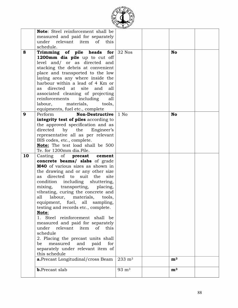
88
Note: Steel reinforcement shall be measured and paid for separately under relevant item of this schedule.
8 Trimming of pile heads for 1200mm dia pile up to cut off level and/ or as directed and stacking the debris at convenient place and transported to the low laying area any where inside the harbour within a lead of 4 Km or as directed at site and all associated cleaning of projecting reinforcements including all labour, materials, tools, equipments, fuel etc., complete
32 Nos No
9 Perform Non-Destructive integrity test of piles according to
the approved specification and as directed by the Engineer’s representative all as per relevant BIS codes, etc., complete. Note: The test load shall be 500 Te. for 1200mm dia.Pile.
1 No No
Casting of precast cement concrete beams/ slabs of grade M40 of various sizes as shown in the drawing and or any other size as directed to suit the site condition including shuttering, mixing, transporting, placing, vibrating, curing the concrete and all labour, materials, tools,
equipment, fuel, all sampling, testing and records etc., complete. Note: 1. Steel reinforcement shall be measured and paid for separately under relevant item of this schedule 2. Placing the precast units shall be measured and paid for separately under relevant item of this schedule
a.Precast Longitudinal/cross Beam 233 m3 m3
10
b.Precast slab 93 m3 m3
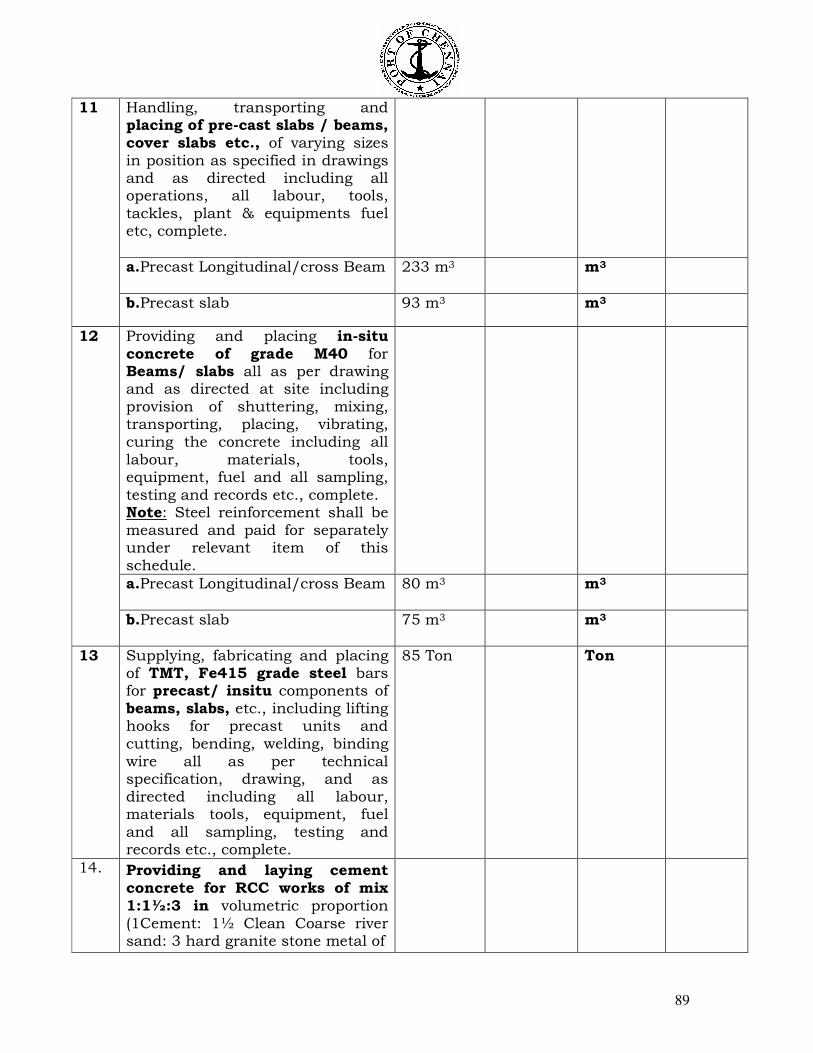
89
Handling, transporting and placing of pre-cast slabs / beams, cover slabs etc., of varying sizes in position as specified in drawings and as directed including all operations, all labour, tools, tackles, plant & equipments fuel etc, complete.
a.Precast Longitudinal/cross Beam 233 m3 m3
11
b.Precast slab 93 m3 m3
Providing and placing in-situ concrete of grade M40 for Beams/ slabs all as per drawing and as directed at site including provision of shuttering, mixing, transporting, placing, vibrating, curing the concrete including all labour, materials, tools, equipment, fuel and all sampling, testing and records etc., complete. Note: Steel reinforcement shall be measured and paid for separately under relevant item of this schedule.
a.Precast Longitudinal/cross Beam 80 m3 m3
12
b.Precast slab 75 m3 m3
13
Supplying, fabricating and placing of TMT, Fe415 grade steel bars for precast/ insitu components of beams, slabs, etc., including lifting hooks for precast units and cutting, bending, welding, binding wire all as per technical specification, drawing, and as directed including all labour, materials tools, equipment, fuel and all sampling, testing and records etc., complete.
85 Ton Ton
14. Providing and laying cement concrete for RCC works of mix 1:1½:3 in volumetric proportion (1Cement: 1½ Clean Coarse river sand: 3 hard granite stone metal of
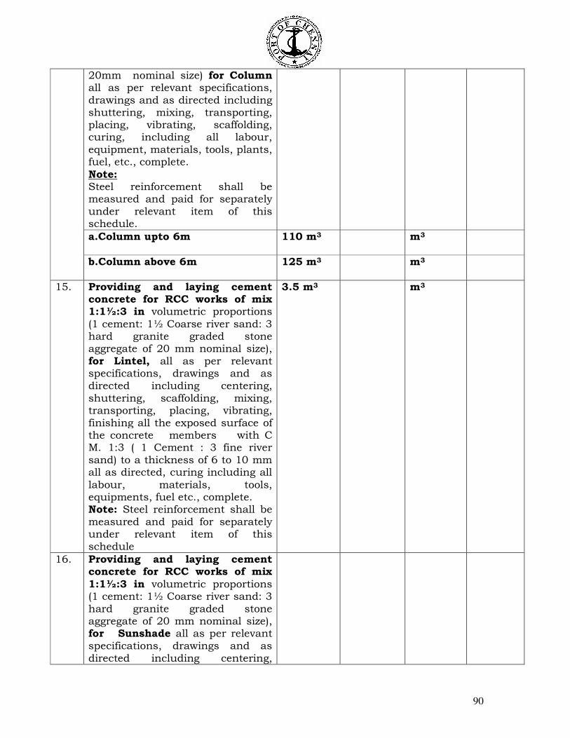
90
20mm nominal size) for Column all as per relevant specifications, drawings and as directed including shuttering, mixing, transporting, placing, vibrating, scaffolding, curing, including all labour, equipment, materials, tools, plants, fuel, etc., complete.
Note: Steel reinforcement shall be measured and paid for separately under relevant item of this schedule.
a.Column upto 6m 110 m3
m3
b.Column above 6m 125 m3
m3
15. Providing and laying cement concrete for RCC works of mix 1:1½:3 in volumetric proportions
(1 cement: 1½ Coarse river sand: 3 hard granite graded stone aggregate of 20 mm nominal size), for Lintel, all as per relevant specifications, drawings and as directed including centering, shuttering, scaffolding, mixing, transporting, placing, vibrating, finishing all the exposed surface of the concrete members with C M. 1:3 ( 1 Cement : 3 fine river sand) to a thickness of 6 to 10 mm all as directed, curing including all
labour, materials, tools, equipments, fuel etc., complete. Note: Steel reinforcement shall be measured and paid for separately under relevant item of this schedule
3.5 m3
m3
16. Providing and laying cement concrete for RCC works of mix
1:1½:3 in volumetric proportions (1 cement: 1½ Coarse river sand: 3 hard granite graded stone aggregate of 20 mm nominal size), for Sunshade all as per relevant specifications, drawings and as directed including centering,
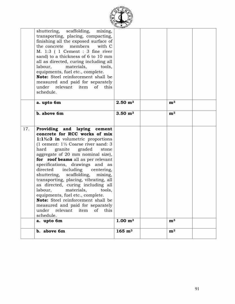
91
shuttering, scaffolding, mixing, transporting, placing, compacting, finishing all the exposed surface of the concrete members with C M. 1:3 ( 1 Cement : 3 fine river sand) to a thickness of 6 to 10 mm all as directed, curing including all labour, materials, tools,
equipments, fuel etc., complete. Note: Steel reinforcement shall be measured and paid for separately under relevant item of this schedule.
a. upto 6m 2.50 m3
m3
b. above 6m 3.50 m3
m3
17. Providing and laying cement concrete for RCC works of mix 1:1½:3 in volumetric proportions (1 cement: 1½ Coarse river sand: 3 hard granite graded stone aggregate of 20 mm nominal size), for roof beams all as per relevant specifications, drawings and as directed including centering, shuttering, scaffolding, mixing, transporting, placing, vibrating, all as directed, curing including all labour, materials, tools, equipments, fuel etc., complete. Note: Steel reinforcement shall be measured and paid for separately under relevant item of this schedule.
a. upto 6m 1.00 m3
m3
b. above 6m 165 m3
m3
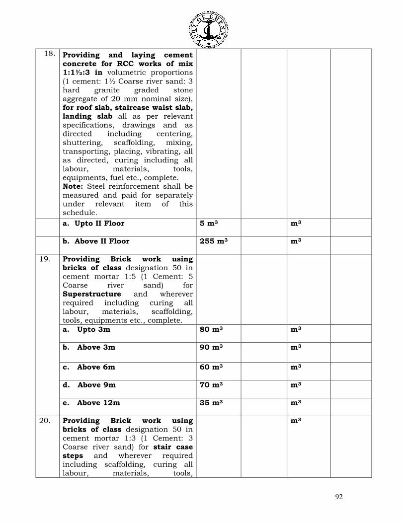
92
18. Providing and laying cement concrete for RCC works of mix 1:1½:3 in volumetric proportions
(1 cement: 1½ Coarse river sand: 3 hard granite graded stone aggregate of 20 mm nominal size), for roof slab, staircase waist slab, landing slab all as per relevant specifications, drawings and as directed including centering, shuttering, scaffolding, mixing, transporting, placing, vibrating, all as directed, curing including all labour, materials, tools, equipments, fuel etc., complete. Note: Steel reinforcement shall be
measured and paid for separately under relevant item of this schedule.
a. Upto II Floor 5 m3
m3
b. Above II Floor 255 m3
m3
Providing Brick work using bricks of class designation 50 in cement mortar 1:5 (1 Cement: 5 Coarse river sand) for Superstructure and wherever required including curing all labour, materials, scaffolding, tools, equipments etc., complete.
a. Upto 3m
80 m3 m3
b. Above 3m
90 m3 m3
c. Above 6m
60 m3 m3
d. Above 9m
70 m3 m3
19.
e. Above 12m
35 m3 m3
20. Providing Brick work using bricks of class designation 50 in cement mortar 1:3 (1 Cement: 3 Coarse river sand) for stair case steps and wherever required including scaffolding, curing all labour, materials, tools,
m3
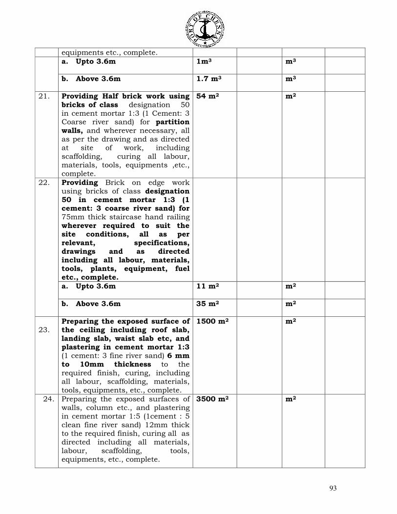
93
equipments etc., complete.
a. Upto 3.6m 1m3 m3
b. Above 3.6m 1.7 m3 m3
21. Providing Half brick work using bricks of class designation 50 in cement mortar 1:3 (1 Cement: 3 Coarse river sand) for partition walls, and wherever necessary, all as per the drawing and as directed at site of work, including scaffolding, curing all labour, materials, tools, equipments ,etc., complete.
54 m2 m2
Providing Brick on edge work using bricks of class designation 50 in cement mortar 1:3 (1 cement: 3 coarse river sand) for 75mm thick staircase hand railing wherever required to suit the site conditions, all as per relevant, specifications, drawings and as directed including all labour, materials, tools, plants, equipment, fuel etc., complete.
a. Upto 3.6m
11 m2 m2
22.
b. Above 3.6m 35 m2 m2
23.
Preparing the exposed surface of the ceiling including roof slab, landing slab, waist slab etc, and plastering in cement mortar 1:3 (1 cement: 3 fine river sand) 6 mm to 10mm thickness to the required finish, curing, including all labour, scaffolding, materials, tools, equipments, etc., complete.
1500 m2 m2
24. Preparing the exposed surfaces of walls, column etc., and plastering in cement mortar 1:5 (1cement : 5 clean fine river sand) 12mm thick to the required finish, curing all as directed including all materials, labour, scaffolding, tools, equipments, etc., complete.
3500 m2
m2
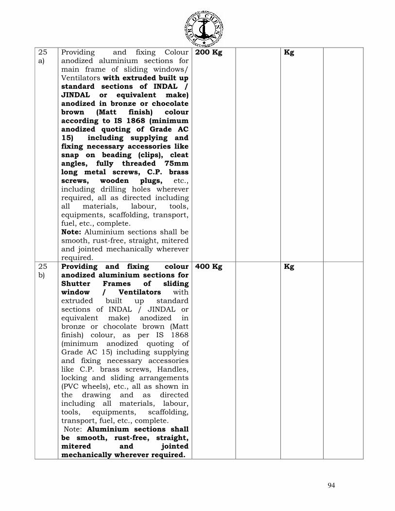
94
25 a)
Providing and fixing Colour anodized aluminium sections for main frame of sliding windows/ Ventilators with extruded built up standard sections of INDAL / JINDAL or equivalent make) anodized in bronze or chocolate brown (Matt finish) colour
according to IS 1868 (minimum anodized quoting of Grade AC 15) including supplying and fixing necessary accessories like snap on beading (clips), cleat angles, fully threaded 75mm long metal screws, C.P. brass screws, wooden plugs, etc., including drilling holes wherever required, all as directed including all materials, labour, tools, equipments, scaffolding, transport, fuel, etc., complete. Note: Aluminium sections shall be smooth, rust-free, straight, mitered and jointed mechanically wherever required.
200 Kg
Kg
25 b)
Providing and fixing colour anodized aluminium sections for Shutter Frames of sliding window / Ventilators with extruded built up standard sections of INDAL / JINDAL or equivalent make) anodized in bronze or chocolate brown (Matt finish) colour, as per IS 1868 (minimum anodized quoting of Grade AC 15) including supplying and fixing necessary accessories like C.P. brass screws, Handles, locking and sliding arrangements (PVC wheels), etc., all as shown in the drawing and as directed including all materials, labour, tools, equipments, scaffolding, transport, fuel, etc., complete. Note: Aluminium sections shall be smooth, rust-free, straight, mitered and jointed mechanically wherever required.
400 Kg
Kg
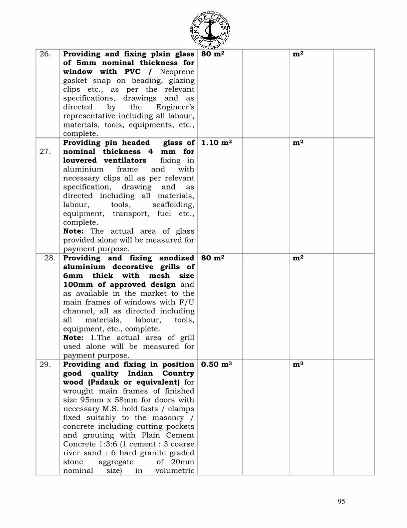
95
26. Providing and fixing plain glass of 5mm nominal thickness for window with PVC / Neoprene gasket snap on beading, glazing clips etc., as per the relevant specifications, drawings and as directed by the Engineer’s representative including all labour,
materials, tools, equipments, etc., complete.
80 m2 m2
27.
Providing pin headed glass of nominal thickness 4 mm for louvered ventilators fixing in aluminium frame and with necessary clips all as per relevant specification, drawing and as directed including all materials, labour, tools, scaffolding, equipment, transport, fuel etc., complete. Note: The actual area of glass provided alone will be measured for payment purpose.
1.10 m2 m2
28. Providing and fixing anodized aluminium decorative grills of 6mm thick with mesh size 100mm of approved design and as available in the market to the main frames of windows with F/U channel, all as directed including all materials, labour, tools,
equipment, etc., complete. Note: 1.The actual area of grill used alone will be measured for payment purpose.
80 m2 m2
29. Providing and fixing in position good quality Indian Country wood (Padauk or equivalent) for wrought main frames of finished size 95mm x 58mm for doors with necessary M.S. hold fasts / clamps fixed suitably to the masonry / concrete including cutting pockets and grouting with Plain Cement Concrete 1:3:6 (1 cement : 3 coarse river sand : 6 hard granite graded
stone aggregate of 20mm nominal size) in volumetric
0.50 m3 m3
96
proportions, curing including painting with one coat of boiling coal tar paint on the portions of the timber abutting against masonry / concrete all as shown in the drawing and as directed including all materials, labour, tools, equipment, etc., complete.
Note: Supplying and fixing of necessary fixtures like butt hinges, tower bolts, etc., will be paid under relevant item of this schedule.
30. Providing and fixing in position Good quality Indian country wood (Padauk or equivalent) single hung panelled shutters for doors with 32mm thick country wood styles including top rail, bottom rail, lock rail etc., and country wood panels of 16mm thick all as per drawing no.CEM/20A/91 (Chennai Port Trust Civil Engineering Works Manual drawing) including all materials, labour, tools, equipments, transport, fuel etc., complete.
10 m2 m2
31. Providing and fixing good quality single leaf factory made pvc rigid foam panelled doors
(Manufactured by M/s Rajshri or equivalent) and 5mm thick and 75mm wide PVC sheets for top rail, lock rail and bottom rail on either side of approved section to suit the existing door openings in toilets with main frame of size 50 x 47 mm with a wall thickness of 5mm made out of extruded 5mm rigid PVC foam sheet mitered at corners and joined with 2 nos. of 150mm long brackets of 15x15mm M.S. square tube, the vertical door
profiles to be reinforced with19x19mm M.S.square tube of 19 gauge in all the three sides with perfect edges, doors main frame
5 m2 m2
97
being secured to walls with steel screw of 100 mm long three nos. each side through the frame by using PVC fasteners and 30mm thick factory made PVC rigid foam panelled door shutter made from MS tubular frame of 19 gauge of 19x19mm(Styles) and 15x15mm
(TOP and bottom rails) M.S. frame to be covered with heat moulded PVC "C" channel of 5mm thick sheet and 30x50mm wide to form styles and 5mm thick 20mm wide cross PVC sheets as gap insert for top rail and bottom rail, panelling of 5mm thick PVC sheet fitted in the M.S. frame welded/sealed to the styles and rails with 5x30mm PVC sheet beading on either side and jointed together with solvent cement adhesive etc., complete with suitable wooden infill packing in door shutter panels to facilitate fixing of fittings all as per manufacturer's specification and as directed including all labour, materials, scaffolding, transport, fuel, tools, equipments, etc., complete. NOTE: The door shall be manufactured to suit the size of the existing opening available at site
32.
Supplying and fixing anodised aluminium (AC 10 grade) fittings for doors, windows etc., with necessary screws all as per relevant specification and drawing and as directed including all
materials, labour, tools, equipments, etc. complete.
a. Butt hinges 150mm long 15 Nos No.
b. Aldrop 250mm long 5 Nos No.
c. Tower bolt 150mm long 5 Nos No.
98
d. Tower bolt 250mm long 10 Nos No.
e. Door stopper
5 Nos No.
f. Handle100mm long
10 Nos No.
33. Providing and fixing ceramic tile flooring using first quality Anti-skid ceramic tiles of size 306mm x 306mm and 7mm nominal thickness (Johnson’s or equivalent) or nearest size as available in the market of approved shade / colour set in C.M 1:3 (1 cement : 3 clean fine river sand) 20mm average thick and fixing the tiles with neat cement slurry with required slope and joints neatly pointed with white
cement added with pigment to match the colour of the tiles, curing all as per relevant specification and as directed including all materials, labour, tools, equipments, etc., complete.
1150 m2 m2
34. Preparing the surfaces of walls and providing skirting with good quality Ceramic Tiles (Plain white / Ivory/ Grey) using 300mmx200mm size 100mm high for skirting (Johnson or equivalent) of nominal thick or nearest size as available in the market of approved pattern and shade, set in cement mortar 1:3 (1 cement : 3 clean river sand) 6 to 10mm thick fixed with neat cement slurry and joints neatly pointed with white cement added with pigment to match the colour of the
tiles curing all as directed including cement and all other materials, labour, tools, equipments, etc., complete
50 m2 m2
35. Providing with and laying antiskid ceramic tiles in risers and treads of staircase steps &
85 m2 m2
99
Toilets of suitable size as available in the market of approved colour, set in C.M 1:3 (1 cement : 3 fine river sand) 20mm thick with neat cement slurry and joints neatly pointed with white cement added with pigment to match the colour of the tiles curing all as
directed including cement and all other materials, labour, tools, equipments., etc complete.
36. Providing wall dadoing in with first quality glazed tile (Jhonson / Kajaria / Somany ) of size 300mm x 200mm x 6mm thickness or nearest size as available in the market of approved colour set in a bedding mortar of 6 to 10 mm thick in cement mortar 1:3 (1 cement : 3 clean fine river sand) and fixing with neat cement slurry and joints neatly pointed with polymer based grout mix ( Bal Endura or Fevimate or equivalent) added with pigment to match the colour of the tiles, curing all as directed including cement and all other materials, labour, tools, equipments, etc., complete.
75 m2 m2
37. Providing and fixing good quality
European type Water Closet White (PARRYWARE or HINDWARE) with 'P' or 'S' trap (to suit the site condition) of approved make and quality with white ABS low level flushing cistern of 10 liters capacity (Slim line of Parryware or equivalent) with 40mm dia flush pipe, plastic seat and cover, fixing T.W. plugs, etc., all in sound working condition all as specified and as directed including all materials, labour,
tools, equipments, etc., complete.
3 Nos. No.
38. Providing and fixing medium
grade G.I Pipes 20 mm dia nominal bore of make like TATA,
20
Running metre
Running
metre)
100
CENTURY or equivalent with necessary G.I specials of "ISI” brand such as tees, bends, couplings, elbows, reducers, unions, etc., for concealed water supply lines to alignment and levels as directed in the walls, cutting, threading the pipes
wherever necessary, joining, painting the pipes with two coats of anticorrosive bitumastic paint, testing the pipes and joints making good the disturbed portions, all as per relevant schedules, specifications, drawings and as directed including all materials, labour, tools, tackles, equipments, etc. complete.
Providing and fixing medium grade G.I Pipes of make like TATA, CENTURY or equivalent with necessary "ISI ” brand ,G.I specials of such as tees, bends, couplings, elbows, reducers, unions, etc., for water supply along the wall, floor for open plumbing to alignment and levels as directed including cutting, threading the pipes wherever necessary joining, covering the pipes with approved quality tapes, painting the pipes with two coats of anticorrosive bitumastic paint, testing the pipeline and joints, and making good the disturbed portions all as specified and as directed at site of work fixing the pipes on walls with special clamps first quality etc., all as per relevant schedules, specifications, drawings and as directed including all materials, labour, tools, tackles, equipments, etc. complete.
a. 25 mm dia nominal bore 30
Running metre
Running
metre)
39.
b. 20 mm dia nominal bore 60 Running
Running metre)
101
metre
Providing and fixing to the pipeline, approved quality gun
metal ball valve suitable for open/concealed plumbing lines as required including testing the joints etc., all as per relevant specification and as directed including all labour, materials, tools, equipments, scaffolding etc., complete.
a. 25 mm dia nominal bore 5 Nos. No.
40.
b. 20 mm dia nominal bore 8 Nos. No.
41. Providing and fixing approved quality Chromium plated brass
screw down taps (long body) of 15 mm nominal bore to suit concealed water lines, C.P. wall flange including testing etc., all as per relevant specifications and as directed including all labour, tools, equipments,materials,etc. complete.
12 Nos. No.
42. Providing and fixing good quality vitreous white wash hand basin 530mm x 440mm size or nearest size as available in the market (Parryware Kingsmere basin or equivalent) with a single 15mm chromium plated brass pillar tap, chromium plated waste fitting, 32mm dia chromium plated brass union, 15mm dia PVC inlet connection, 32mm dia PVC waste pipe fittings, a pair of cast iron brackets as available in the market suitable for fixing the wash hand basin, including painting the brackets, etc. with two coats of synthetic enamel paint over one coat of primer, fixing the brackets with teakwood plug and making good the disturbed portion, etc., all in sound working condition all as per relevant specification and as directed including all materials, labour, tools, equipments etc.
6 Nos. No.
102
complete.
43. Supplying and fixing on wall, face mirror (Saint Gobain or
equivalent) of size 610x450mm with PVC moulded frames of approved quality as directed including all materials, labour, tools, equipments, etc., complete.
6 Nos. 1No. (One
Number)
44. a)
Providing, laying and linking to correct alignments and gradient rigid unplasticised 50mm nominal bore PVC pipes (4Kgf/cm2) (Finolex or equivalent) including jointing with seal ring for waste water and with necessary tees, bends, plain and with access cap, coupling, cowls etc., cutting and jointing the pipes,
punching masonry or concrete wherever necessary, fixing to the walls with PVC clamps, making holes in walls/concrete surfaces, including conveying the pipes, providing and fixing PVC pipe connections for joining outlet of sanitary ware and traps, testing all as per specifications drawings and as directed including all labour, materials, tools, joints, equipments etc., complete. Note: The rate is to include the
cost of cutting the masonry to the required size for taking the PVC pipe including making good the disturbed portion.
20 RM 1 running metre)
44. b)
Providing, laying and linking to correct alignments and gradient rigid unplasticised 75mm nominal bore PVC pipes (4Kgf/cm2) (Finolex or equivalent) including jointing with seal ring for waste water and with necessary tees, bends, plain and with access cap, coupling, cowls etc., cutting and jointing the pipes, punching masonry or concrete
wherever necessary, fixing to the walls with PVC clamps, making
35 Running metre
Running metre)
103
holes in walls/concrete surfaces, including conveying the pipes, providing and fixing PVC pipe connections for joining outlet of sanitary ware and traps, testing all as per specifications drawings and as directed including all labour, materials, tools, joints, equipments
etc., complete. Note: The rate is to include the cost of cutting the masonry to the required size for taking the PVC pipe including making good the disturbed portion.
45. Providing and fixing in position 75mm dia. PVC Floor trap with inlets and outlets of approved quality including fabricating the extension piece as per the site condition embedding the trap in the floor / slab in plain cement concrete of mix 1:3:6 mix (1 cement : 3 coarse river sand : 6 hard granite graded stone aggregate of 20mm nominal size) with suitable grating, making the joints water tight etc., all as per relevant specification and as directed including all labour, materials, equipments, tools, etc., complete.
8 Nos. No.
46. Preparing the surfaces of the Ceiling, bottom of sunshade etc., and applying with three coats of white wash using lovelycem or equivalent to give an even shade including all labour, scaffolding, materials, brushes, tools, equipments, etc., complete.
1500 m2 m2
47. Preparing the internal and external surfaces of wall, column, parapet, Sunshade etc., and applying two coats of colour wash using water proofing cement paint (Supercem or equivalent) over a priming coat (white) to give an
even shade, curing, scaffolding etc., including all labour,
3430 m2 m2)
104
materials, brushes, etc., complete.
48. Preparing the surfaces of all new wooden members and painting
with two coats of synthetic enamel paint of approved quality and even shade over a coat of primer including all labour, brushes, materials, tools, tackles, equipments, scaffolding etc., complete. NOTE: Painting co-efficient over the measured quantity shall be allowed as stipulated in the manual.
30 m2 m2
49. Providing and fixing manually operated mild steel rolling shutter of approved make using 80mm x 1.2 mm M.S laths
(thickness not less than 1 mm) interlocked together through their entire length and joined together at ends by heavy mild steel end locks mounted on specially designed pipe shaft with necessary wire springs, brackets, ball bearings side guides and arrangements for inside and out side locking with pull and push type of operations and providing and fixing M.S hood cover to the rolling shutters made out of 1.2 mm thick M.S sheet including
painting the shutter and hood cover with one coat of zinc chromate primer, all as per Chennai Port Trust civil Engineering manual –Drg. No. CEM/31A/91, technical specifications and as directed. Including all labour materials, tools, equipments, scaffolding etc, complete.
20 m2 m2
50. Preparing the surfaces of all new steel members and painting with two coats of synthetic enamel paint of approved shade including all labour, brushes, materials,
tools, equipments, scaffolding etc., complete.
40 m2 m2
105
NOTE: Painting co-efficient over the measured quantity shall be allowed as stipulated in the manual
51. Providing and laying unplasticised rigid PVC rain water down take pipes of 110mm outside dia (Truebore or equivalent) (4 Kgf/cm2) with necessary bends, shoes, specials, etc., on wall surface with necessary PVC special clamps including cutting pockets in masonry/concrete of size 100 x 100 x 100 mm embedding the clamps in PCC 1:2:4 ( 1 cement: 2 coarse river sand : 4 hard granite graded stone aggregate of 20 mm nominal size) and making good the disturbed portions and joining the pipe with suitable adhesives all as directed including curing all labour, materials, tools, equipments, scaffolding, etc., complete.
90 Running metre
Running Metre)
52. Supplying,transporting, fabricating and placing in position HYSD (Fe 415 grade) steel bars as reinforcements for all RCC works wherever required including handling, cutting,
bending and tying them in position with 1.25mm dia black annealed steel binding wire including all materials, labour, tools, equipments, scaffolding, etc. complete. Note: The rate shall be inclusive of cost of steel, binding wire and fabrication charge etc., complete
100 Ton Ton
53. Providing weathering course for roof slab with brick jelly lime concrete to an average thickness of 75 mm laid to necessary falls and slope of with 20 mm nominal size brick aggregate and 50% lime
mortar 1:2 (1 Lime putty: 2 Surkhi) rammed and finished with gur and
50 m3 m2
106
belgiri treatment complete including rounding off junctions of roof slab with parapet wall all as per the details shown in the drawings specifications and as directed at site of works including curing all labour, materials, tools, equipments, transport, fuel etc.,
complete.
54. Providing and laying over lime concrete terracing on roofs, one course of pressed clay tiles of size 230 mm x 230 mm or of sizes available in local market with the prior approval of Engineers' representative with thickness not less than 18 mm and set in C.M. 1:3 (1 cement: 3 clean coarse river sand) 12mm thick mixed with 2% of integral water proofing compound by weight of cement including pointing the joints of tiles with cement mortar 1:3 (1 cement: 3 clean fine river sand) added with WPC and finished neat, all details as per specifications, drawings and as directed, including curing, all labour, materials, tools, equipments etc., complete.
550 m2
m2
55. Providing and fixing polished
Cuddapah slab 25 mm thick for cupboards as directed at site and suitably fixed with C.M. 1:3 (1 Cement: 3 clean coarse river sand) all as per relevant specifications and drawings etc., including polishing all exposed surfaces of the slab including all labour, materials, Cement, tools, equipments, curing etc., complete.
20 m2 m2
56. Providing and fixing good quality white urinal basin (New Magnum of Parryware or Hindware )of size as per manufacturer’s specification including C.P. Bottle trap and
required accessories with all fittings and fixtures for inlet and
3 Nos No
107
outlet arrangements like spreader, gratings etc., all as directed including all labour, materials, tools, tackles, equipments etc., complete.
57. Providing and fixing both side pre polished marble slabs of size 450 mm x 1200 mm of thickness 18 mm with half round edges at top & bottom of front portion and fixed as partition between urinals including fixing the slab to the walls with stainless steel clamps / screw etc., including making good the disturbed portion, all as per specifications and as directed at site of work including all labour and other materials, tools, equipment etc., complete.
3 Nos No
SIGNATURE
OFFERER SEAL DATE

108
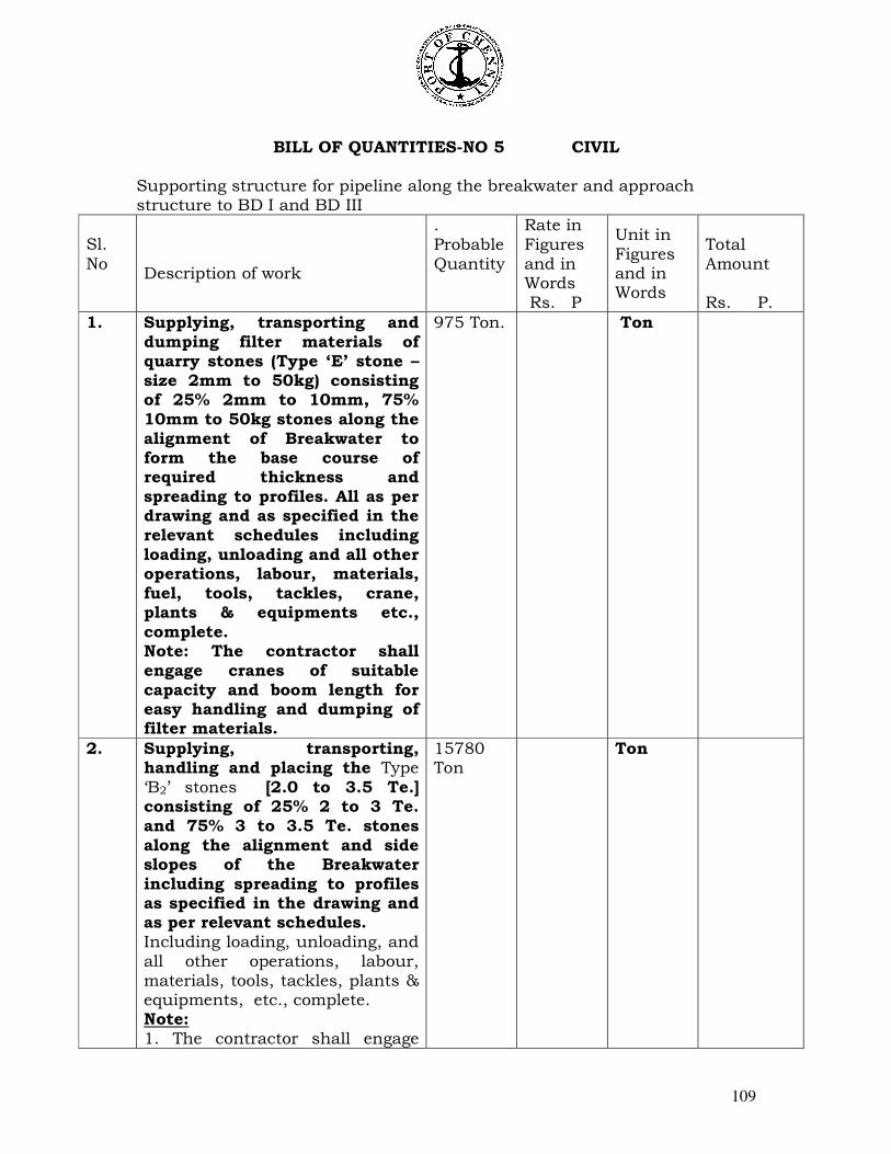
109
BILL OF QUANTITIES-NO 5 CIVIL Supporting structure for pipeline along the breakwater and approach structure to BD I and BD III
Sl.
No
Description of work
. Probable Quantity
Rate in Figures and in Words Rs. P
Unit in Figures and in Words
Total Amount Rs. P.
1. Supplying, transporting and dumping filter materials of quarry stones (Type ‘E’ stone – size 2mm to 50kg) consisting of 25% 2mm to 10mm, 75% 10mm to 50kg stones along the alignment of Breakwater to form the base course of required thickness and spreading to profiles. All as per drawing and as specified in the relevant schedules including loading, unloading and all other operations, labour, materials, fuel, tools, tackles, crane, plants & equipments etc., complete. Note: The contractor shall engage cranes of suitable capacity and boom length for easy handling and dumping of filter materials.
975 Ton. Ton
2. Supplying, transporting, handling and placing the Type ‘B2’ stones [2.0 to 3.5 Te.] consisting of 25% 2 to 3 Te. and 75% 3 to 3.5 Te. stones along the alignment and side slopes of the Breakwater including spreading to profiles as specified in the drawing and as per relevant schedules. Including loading, unloading, and all other operations, labour, materials, tools, tackles, plants & equipments, etc., complete. Note: 1. The contractor shall engage
15780 Ton
Ton
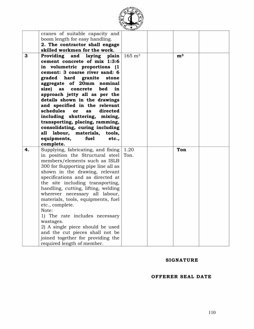
110
cranes of suitable capacity and boom length for easy handling. 2. The contractor shall engage skilled workmen for the work.
3 Providing and laying plain cement concrete of mix 1:3:6 in volumetric proportions (1 cement: 3 coarse river sand: 6 graded hard granite stone aggregate of 20mm nominal size) as concrete bed in approach jetty all as per the details shown in the drawings and specified in the relevant schedules or as directed including shuttering, mixing, transporting, placing, ramming, consolidating, curing including all labour, materials, tools, equipments, fuel etc., complete.
165 m3 m3
4. Supplying, fabricating, and fixing in position the Structural steel members/elements such as ISLB 300 for Supporting pipe line all as shown in the drawing, relevant specifications and as directed at the site including transporting, handling, cutting, lifting, welding wherever necessary all labour, materials, tools, equipments, fuel
etc., complete. Note: 1) The rate includes necessary wastages. 2) A single piece should be used and the cut pieces shall not be joined together for providing the required length of member.
1.20 Ton.
Ton
SIGNATURE
OFFERER SEAL DATE
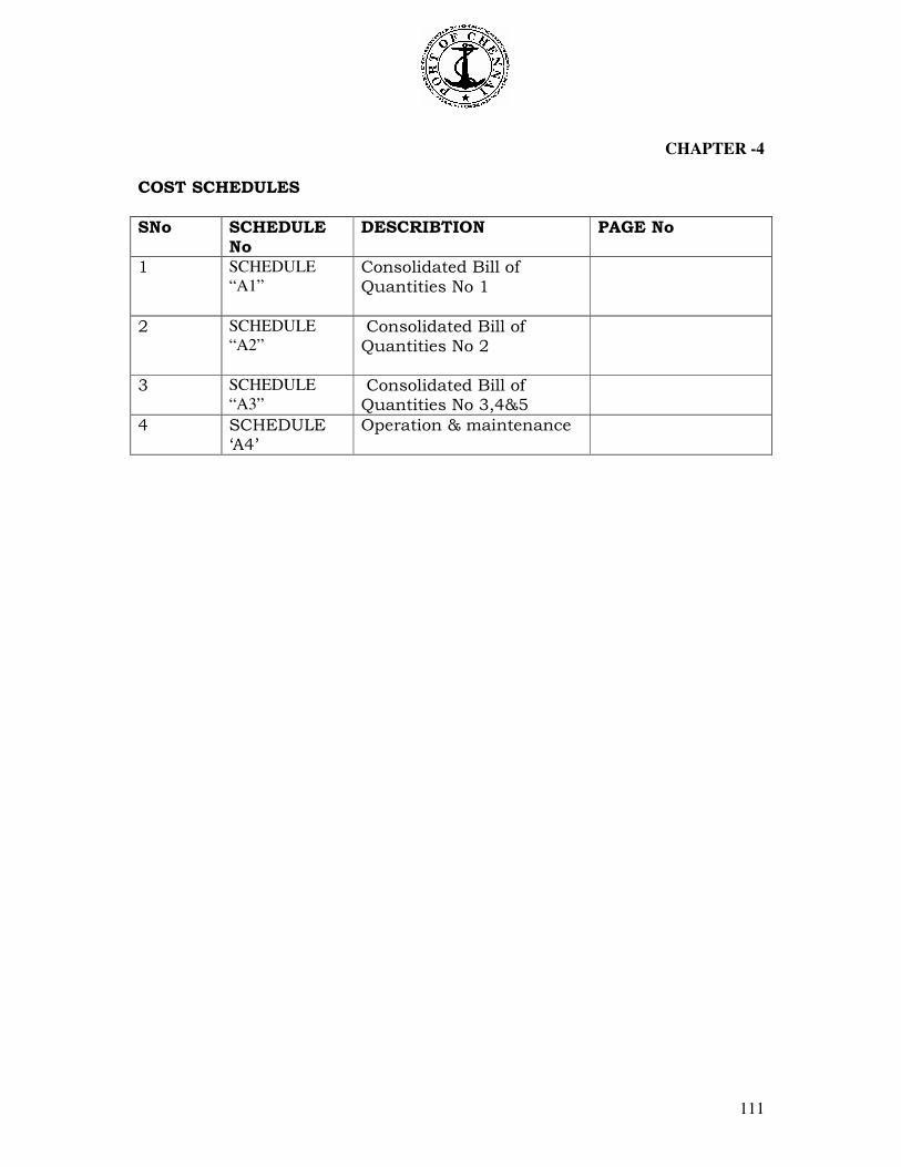
111
CHAPTER -4 COST SCHEDULES
SNo SCHEDULE No
DESCRIBTION PAGE No
1 SCHEDULE
“A1” Consolidated Bill of Quantities No 1
2 SCHEDULE
“A2”
Consolidated Bill of Quantities No 2
3 SCHEDULE
“A3”
Consolidated Bill of Quantities No 3,4&5
4 SCHEDULE ‘A4’
Operation & maintenance

112

113
COST SCHEDULE SUB: “Budgetary offer for “DESIGN, MANUFACTURE, FABRICATION,
SUPPLY, ERECTION, TESTING, COMMISSIONING AND HANDING OVER OF THE NEW FIRE FIGHTING FACILITIES INCLUDING PUMP HOUSE AND LAYING OF POWER ELECTRICAL CABLE FROM EXISTING NEW PUMPHOUSE TO PROPOSED PUMP HOUSE FOR BHARATHI DOCK I & III AT CHENNAI PORT TRUST AND REMOVAL OF THE EXISTING FIRE FIGHTING SYSTEM AND TRANSPORT TO RSA YARD WITH OPERATION AND MAINTENANCE OF THE ENTIRE FIRE FIGHTING FACILITIES INCLUDING PUMP HOUSE FOR A PERIOD OF FIVE YEARS AT BD I& BDIII OF CHENNAI PORT TRUST ” as per the Trust specifications. SCHEDULE “A1” (Consolidated Bill of Quantities No 1)
Item no Description Total Cost
1 The total cost for the removal of the existing fire fighting system at Oil Docks and Transportation to RSA Yard excluding Transportation, Insurance, Taxes & duties if any. (lump sum)
2
The total cost for the Design, Manufacture, Fabrication and Supply, Erection, Testing, Commissioning and Handing over of fire Fighting Facilities at Bharathi Dock I and Bharathi Dock III, of entire Fire Fighting Equipments, accessories for Mechanical
Components and Erection (As per Bill of Quantities no1) excluding Transportation, Insurance, Taxes & duties.
3 Excise Duty if any (percentage)
4 Sales Tax if any (percentage)
5 Transport Charges
6 Transit Insurance Charges
7 Service Tax
8 Work Contract Tax if any
TOTAL
NOTE: a. The Budgetary offered shall furnish the quoted amount in words and figures.
b. The Tenderer shall furnish applicable taxes, duties clearly in percentage in words.
c. C and D forms will not be issued by the Trust.
DATE: SIGNATURE OFFERER SEAL & DATE
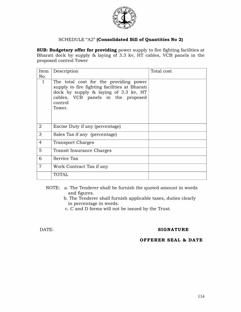
114
SCHEDULE “A2” (Consolidated Bill of Quantities No 2) SUB: Budgetary offer for providing power supply to fire fighting facilities at Bharati dock by supply & laying of 3.3 kv, HT cables, VCB panels in the proposed control Tower
Item No.
Description Total cost
1
The total cost for the providing power supply to fire fighting facilities at Bharati dock by supply & laying of 3.3 kv, HT cables, VCB panels in the proposed
control Tower.
2 Excise Duty if any (percentage)
3 Sales Tax if any (percentage)
4 Transport Charges
5 Transit Insurance Charges
6 Service Tax
7 Work Contract Tax if any
TOTAL
NOTE: a. The Tenderer shall be furnish the quoted amount in words
and figures. b. The Tenderer shall furnish applicable taxes, duties clearly
in percentage in words. c. C and D forms will not be issued by the Trust.
DATE: SIGNATURE
OFFERER SEAL & DATE

115
SCHEDULE “A3” (Consolidated Bill of Quantities No 3,4&5)
Subject: Budgetary offer for proposed construction of pump house and control tower
with supporting structure for pipeline at Eastern side of Eastern breakwater at
Bharathi dock.
Entire Civil Works Construction including material
Item No.
Description Total cost
1 Construction of Approach jetty from existing Breakwater to proposed Pump room and control tower.
2 Construction of main jetty and pump room and control tower outside the break water.
3 Supporting structure for pipe line along
the breakwater and approach structure to BDI & BDIII.
4 Insurance Charges if any
5 Service Tax
6 Work Contract Tax if any
TOTAL
NOTE: a. The Tenderer shall be furnish the quoted amount in words and
figures.
b. The Tenderer shall furnish applicable taxes, duties clearly in percentage in words.
c. C and D forms will not be issued by the Trust.
DATE: SIGNATURE
OFFERER SEAL & DATE
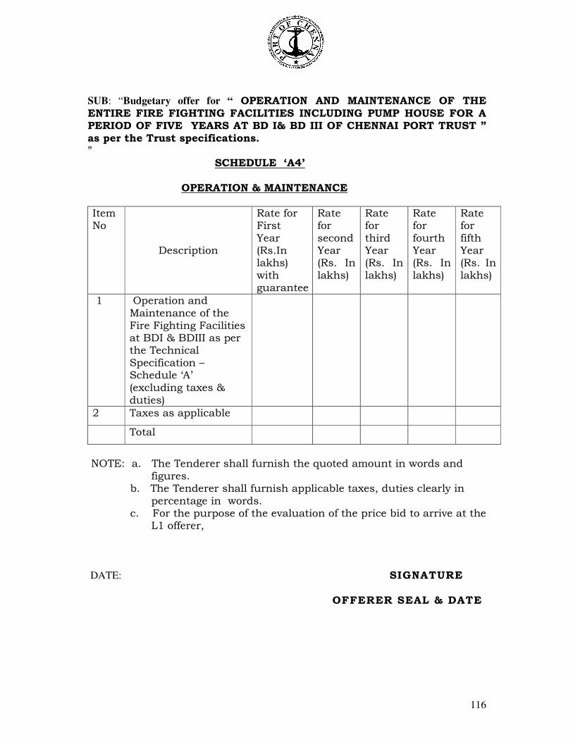
116
SUB: “Budgetary offer for “ OPERATION AND MAINTENANCE OF THE
ENTIRE FIRE FIGHTING FACILITIES INCLUDING PUMP HOUSE FOR A PERIOD OF FIVE YEARS AT BD I& BD III OF CHENNAI PORT TRUST ” as per the Trust specifications. ”
SCHEDULE ‘A4’
OPERATION & MAINTENANCE
Item No
Description
Rate for First Year (Rs.In lakhs) with guarantee
Rate for second Year (Rs. In lakhs)
Rate for third Year (Rs. In lakhs)
Rate for fourth Year (Rs. In lakhs)
Rate for fifth Year (Rs. In lakhs)
1 Operation and Maintenance of the Fire Fighting Facilities at BDI & BDIII as per the Technical Specification – Schedule ‘A’ (excluding taxes & duties)
2 Taxes as applicable
Total
NOTE: a. The Tenderer shall furnish the quoted amount in words and
figures. b. The Tenderer shall furnish applicable taxes, duties clearly in
percentage in words. c. For the purpose of the evaluation of the price bid to arrive at the
L1 offerer,
DATE: SIGNATURE
OFFERER SEAL & DATE
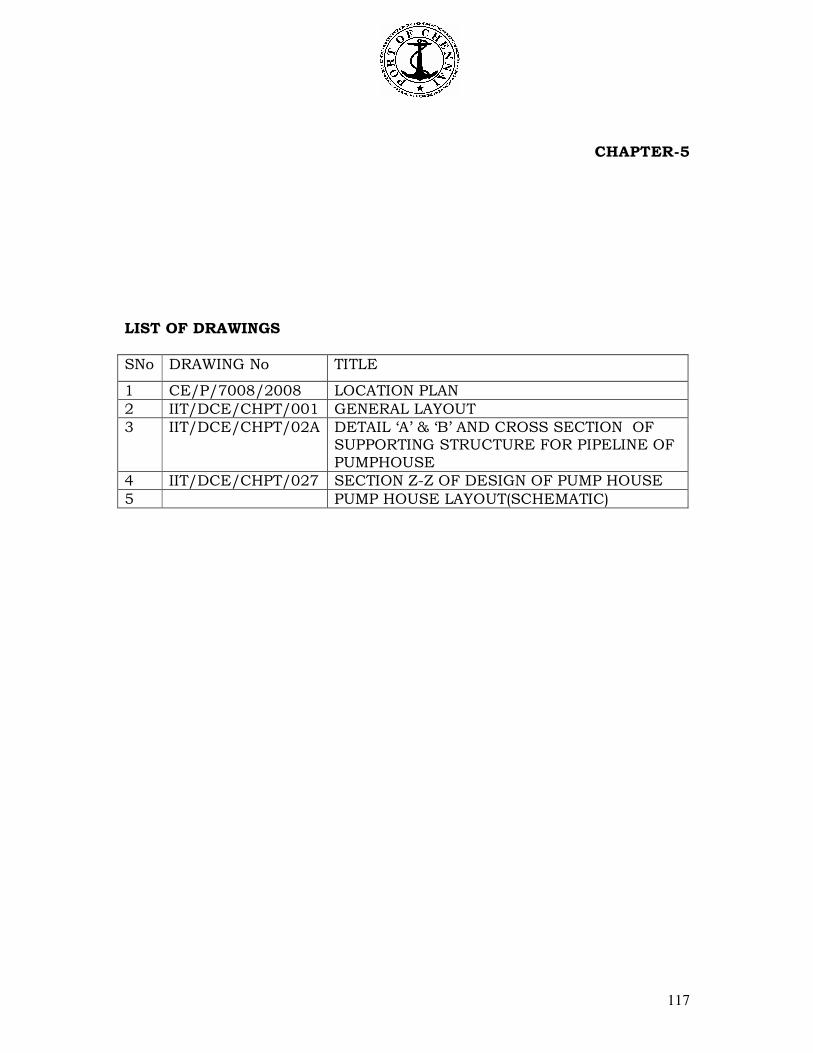
117
CHAPTER-5 LIST OF DRAWINGS
SNo DRAWING No TITLE
1 CE/P/7008/2008 LOCATION PLAN
2 IIT/DCE/CHPT/001 GENERAL LAYOUT
3 IIT/DCE/CHPT/02A DETAIL ‘A’ & ‘B’ AND CROSS SECTION OF SUPPORTING STRUCTURE FOR PIPELINE OF PUMPHOUSE
4 IIT/DCE/CHPT/027 SECTION Z-Z OF DESIGN OF PUMP HOUSE
5 PUMP HOUSE LAYOUT(SCHEMATIC)
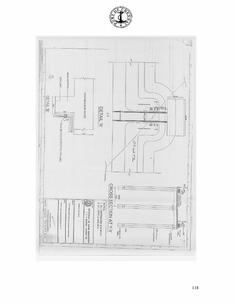
118
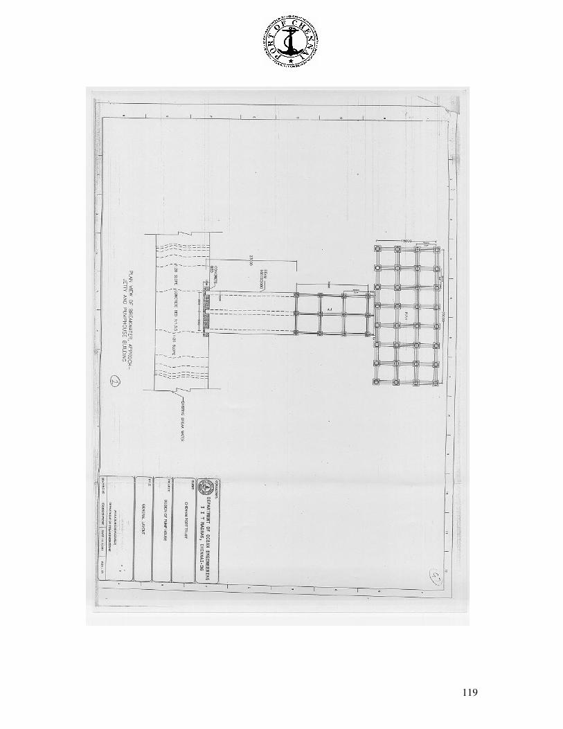
119
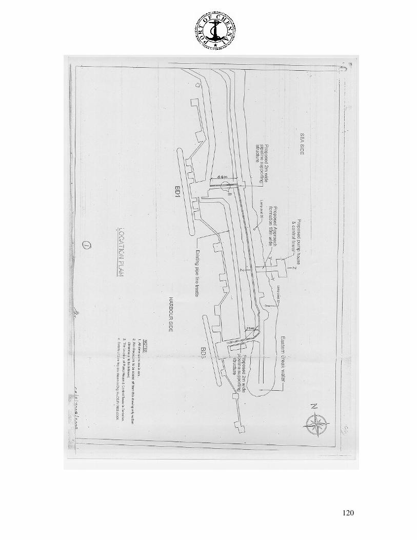
120
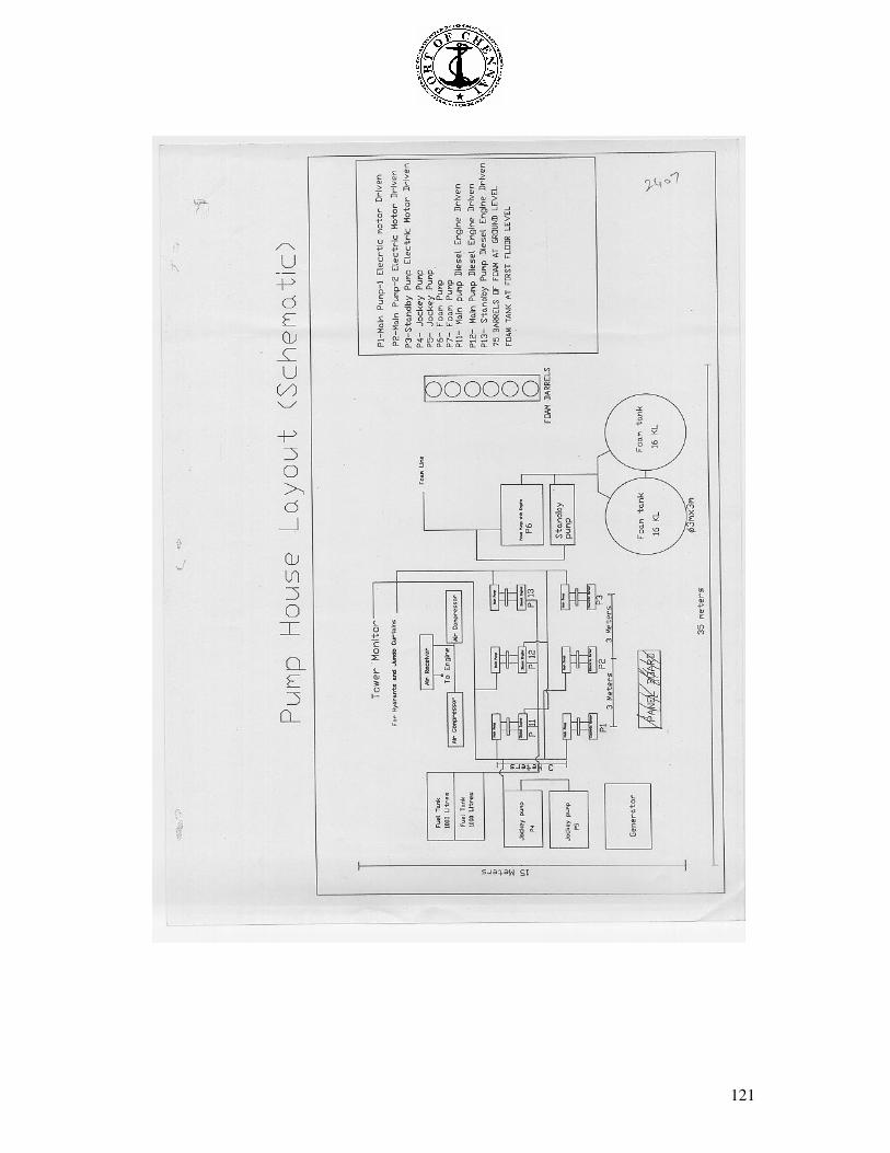
121
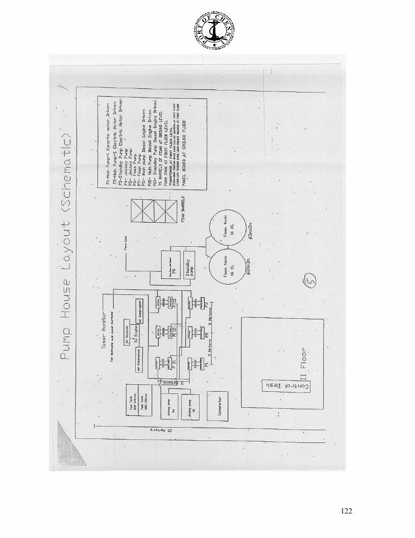
122
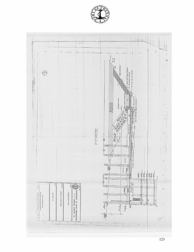
123