Embed Size (px)
Citation preview

1
Joint Techs/APAN Conference
Honolulu, HawaiiJanuary 29, 2004
Jerry SobieskiDirector,
Research & Technology Development
Mid-Atlantic Crossroads
Optical NetworkingOverview of the Terminology, Technology,
Architectural Issues and Aspects of Associated
Business/Financial Issues

Disclaimers
This presentation is only meant as skeleton for discussion
The speaker is not the expert in all (or necessarily any) of the topics discussed

The Justification for R&E customized optical networks
The commercial sector has trouble convincing itself to build leading edge networks unless/until there is enough uptake to generate [sufficient] return on the investment
The R&E community isn’t large enough (by itself) to justify the investment by the carriers
The R&E community have rather different requirements than the business/commercial sector
The R&E community can’t afford commercial pricing

Why does the R&E community think they are able to build them?
The resources are provided at a “cost” basis rather than a “market” basis I.e. the profit motive is [in theory] substantially less, hopefully
reducing TCO The R&E community collaborates, where as the private
sector competes – shared costs and combined financial resources
The “early adopter” service requirements are different than commercialized production services
The R&E community must build them in order to have the infrastructure required to experiment and develop new service models and capabilities

Why is “Optical” Networking so important?
Understanding -To explore, we need a common basic understanding of the optical technology, capabilities, architectural/engineering tradeoffs, and future evolutionary roadmap
Experience - We need real examples and first hand experience to truly understand the implications for the R&E needs.
Prioritization - We need to identify and prioritize our requirements and map them to our resources (I.e. finances, partners, facilities, timeframes, etc)

Outline of Discussion
Brief review of optical concepts and current technology
Discussion of architectural design considerations when planning an optical deployment
Discussion of some of the business issues associated with optical services

What Optical Network?
Most folks think of wave division multiplexing and all fiber (no copper) based connectivity
A few think of the “all optical” or “passive” or transparent optical transport properties of optical networking
The cognicenti include all optical switching, buffering, and other packet processing.

Optical Networking Building Blocks
Network elements (nodes) Laser types, characteristics, coding formats Transponders, transceivers Multiplexors and demultiplexors Switching technologies
Protection switching OADMs Wavelength switching
Amplification and regeneration Fiber (links)
Fiber types, characteristics Applications (campus, metro, long haul, etc) Engineering issues
Attenuation, Dispersion Other non-linear effects

Network Nodes
Optical nodes need to combine several functions: Add/drop of wavelengths Wavelength conversion to CPE interfaces Signal regeneration Wavelength routing (switching and/or
translation) Wavelength amplification/equalization

Components and Terminology
Optical Add/Drop Mux (OADM) Adds or drops a wavelength(s) to/from the fiber, Passes (ignores) other wavelengths.
Optical channel modules Convert traditional laser interfaces to ITU “grid
compliant” wavelengths (e.g. 1310nm to/from ITU33) Perform other regeneration functions (retiming,
reshaping)

Optical Add/Drop Multiplexor
Mux Dmux
Dmux Mux
Channel Modules
Two fiber example Possibly from a ring configuration
OADM
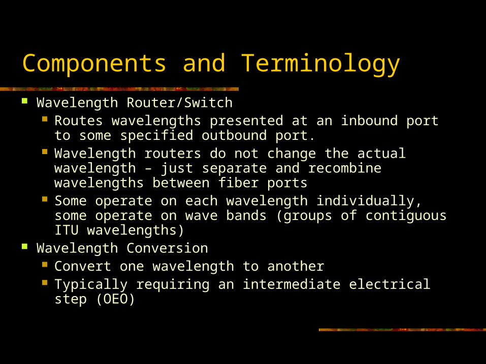
Components and Terminology Wavelength Router/Switch
Routes wavelengths presented at an inbound port to some specified outbound port.
Wavelength routers do not change the actual wavelength – just separate and recombine wavelengths between fiber ports
Some operate on each wavelength individually, some operate on wave bands (groups of contiguous ITU wavelengths)
Wavelength Conversion Convert one wavelength to another Typically requiring an intermediate electrical step (OEO)

Components and Terminology
Wavelength Translation Copy the modulated signal from one wavelength to
another All Optical
Amplifiers All optical device used to amplify optical signals
Erbium Doped Fiber Amplifier (EDFA) Utilizes a “pumping” laser and erbium doped fiber to amplify all
signals in a broad range of wavelengths (C band lambda’s ~1450 nm to 1600 nm)
Raman amps – better SNR, higher power optics
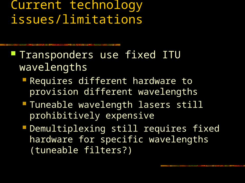
Current technology issues/limitations
Transponders use fixed ITU wavelengths Requires different hardware to provision
different wavelengths Tuneable wavelength lasers still prohibitively
expensive Demultiplexing still requires fixed hardware
for specific wavelengths (tuneable filters?)

Optical Architectures
Design Objectives Advanced Technology? Cost reduction? Both?
Cost efficiency – reduce the overall cost of providing necessary services What are the “necessary” services?
Production needs of the users – I.e. dependable, inexpensive, but [typically] not technologically leading edge. Ex: Commodity internet access
Advanced (“experimental”) capabilities for research applications – I.e. new types of services that support emerging applications requirements.
Network research and experimentation

The Overlay Model Upper layers (e.g.layer 2/3) are unaware of the
underlying transport layer Simple (from the upper layers) – consistent with current
sonet transport layers Upper layers have no control or knowledge of lower
layer topology

The Peer Model
Network layers interact with the transport layer to request resources
Implies a control plane interface (and some level of routing interaction)

One Potential NoF: Concept A
OADM
X
X
XX X
XX
XX
X
International links
WavelengthRouter
IP Router
RON or campus
Fiber Routes

Characteristics of Concept A
National administrative domain Optical transport layer – peer model
Dynamic & flexible bandwidth provisioning Fewer IP routers – but probably bigger (!)
Full mesh between core routers using diverse lambda routing
Delivers IP/lambda to gigapops/RONs Gigapops can peer at optical layer and/or IP
layer. IP peering at multiple core nodes
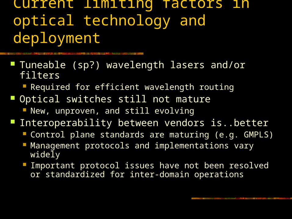
Current limiting factors in optical technology and deployment
Tuneable (sp?) wavelength lasers and/or filters Required for efficient wavelength routing
Optical switches still not mature New, unproven, and still evolving
Interoperability between vendors is..better Control plane standards are maturing (e.g. GMPLS) Management protocols and implementations vary
widely Important protocol issues have not been resolved or
standardized for inter-domain operations

Limiting factors (cont.)
Integration of WDM technology directly into routers, layer2 switches, workstations, etc. Interfaces that operate on the ITU grid will eliminate OEO
conversion at the WDM interface “ITU gbic”s – eliminate OEO stage
Optical UNI Access to dim/dark fiber is still non-trivial and
expensive task In the major metro areas it is improving But the rural land grant institutions are still struggling
Many Universities are not topologically near major telecom hubs or in dense, fiber rich metro regions. How do we solve this problem?

Optical Network Design Objectives
Cost Efficiency and Advanced Technology are not diametrically opposed concepts Regional optical networks provide a significant flexibility
to the user community: Service capabilities are defined to the community’s needs
Do not require the critical mass business case typical of large commercial carriers (Note: this does not mean these services can be provided for free!)
Multi-institutional involvement allow for effective utilization of the investment
making large investments in regional infrastructure possible in the first place,
and reducing the individualized costs of services to each institution

Optical Network Design Strategies:Choosing the Points of Presence
Careful selection of peering points and/or PoPs Locations that will provide the necessary
interconnections and services for the long term – 7 years or longer (upstream services)
Lit services Fiber access Provider competition (two friends are better than one)
Establish PoPs that benefit otherwise telecom challenged neighboring regions/metro areas (downstream services)
Increases consortial critical mass

Optical Network Design Strategies:Choosing the Points of Presence
Long term prospects and value of the network POPs allows for for long term investment by the network and served community in fiber to one (or more) of the POPs Universities are stable (to a fault) Commercial “telco hotels” provide [relatively] easy cross
connects to/from the RON and other service providers Colocation space availability – consider expansion requirements
over the long term, personnel access issues, etc Vendor neutral Meet-Me rooms National and international telecom access
Able to incorporate private fiber built in from user community Entrance/access permission for fiber provider

Points of Presence A MAX Example
CLPKCollege Park, MD University of Md-Verizon, ATT, Qwest, Fibergate, Yipes-NGIX-NASA, NLM/NIH, NOAA, USM
DCNE
Washington, DC NorthEastQwest Communications Terapop-Qwest (primarily), MFN, Verizon, others-Abilene, Esnet, Qwest DIA, Bossnet, …ARLG
Arlington, VAUSC/ Information Sciences Institute East - Verizon, Qwest, MFN, Level3…-ISI-East, NSF, NCSA Access, …
DCGW
Washington, DC George Washington University - Verizon, Qwest, Level3, RCN…-GWU, Georgetown, CUA, USNO …

Optical Design Objectives Interconnecting the POPs
Fiber architecture needs to be: Of suitable grade and/or quantity to carry anticipated services
DWDM capability and modulation rate are a primary concern for current and future transport services
Often simply lighting new fiber pairs is more cost effective (and sometime the only viable way to support new technology rollouts.)
Diverse whenever possible to address redundancy and survivability issues
Rings are the traditional method, meshes are becoming more common
Minimize path length to reduce cost and span-length engineering complexities
Able to incorporate private fiber built in from user community Entrance/access permission for fiber provider
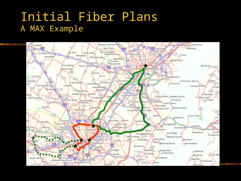
Initial Fiber PlansA MAX Example

Fiber Routes
CLPK
DCNE
ARLG
DCGW
BALT
NWVA
GMUAMCLNPAIX
NLM
NIH
GU
NCSA
NOAAHHMI GSFC
JHU
NARA
UMCP
ISIE
USM
GWU
USNO
GWAS

Optical Network Service Objectives
Balancing act - Anticipating long term optronics and fiber engineering requirements and dependencies is difficult at best
MUST consider the useful life of current technology and plan for rollover However, cannot wait to deploy current advanced technology until
futures are resolved – you won’t make progress. IMO, three year technology cycles is reasonable – useful life may be longer
for less
The types of services the RON will provide near term will drive fiber and optronics requirements:
Anticipated transmission rates require careful attention to dispersion characteristics of the fiber, span lengths, ILAs, etc
Types of transport to be provided will require careful selection of optronics components, wave plan, etc (e.g. TDM vs WDM vs SDM)

Optical Network Service Objectives
Range and dynamics of the optical network will increase complexity Persistent point to point transport in the campus/metro area is
simple(r) Protected rings, meshes, aggregated services are less simple Long haul transport systems are not simple Dynamically reconfigurable and/or shared dedicated services
are complex

Optical Network Service Objectives
Interactions between the transport layer and higher layer services must be understood E.g. automated protection switching implemented at the optical
layer, framing layer, and/or IP layer can lead to protection storms
Control plane implications must be considered for Peer model E.g. Is the control plane for the transport layer carried within upper
layers? What happens to the control plane when/if a transport layer failure occurs?
Ctrl Plane issues may be important if only for operations and management of the network (I.e. even if user access is not allowed)

Business Management Issues of Optical Services
Service Definition What does the user actually receive?
Sonet? Ethernet? FibreChannel? ITU wavelength? Where is the demarc? (a centralized POP or user prem?) Is this persistent? Dedicated? or shared? (I.e. TDM vs
Statistically allocated) What are the service guarantees?
MTBF - Protected? Two 9’s or five 9’s? MTTR? What is the term of the contract?
How long will you be committed to providing this service? Longer terms provide better amortization rates (to the user) Longer terms may increase risk to provider: out year costs may
not be known Shorter terms are more front loaded capital intensive
Pricing Optical Transport Services Cost basis:
Cost = ammortized costs +incremental +operations+ depreciation + margin
Ammortized infrastructural costs Capital expenditure for base infrastructure (first operational wave)
Fiber IRUs, construction/improvements, network elements, amplfiers, etc along path
Cost of money… Incremental cost of additional waves
End points plus intermediate components (amps, mux/dmux, regen, protection components, etc.)
Incremental costs are [in general] difficult to generalize to a fixed cost/wave
Different end points will require different intermediate components (e.g. amps or regen), and the costs associated with specific paths may vary

Cost Basis (cont.) Operating Expenses – monitoring, maintenance, provisioning,etc
Function of network activity – more changes create higher operations costs
Includes other non-capital expenses such as colo lease, office space, insurance, etc.
Sparing is currently an expensive prospect with hardware specific transponders
Personnel requirements: skill sets, coverage and availability, etc Optical (WDM) engineering experience is scarce Support equipment (test lab, field test gear- OTDR, OSA, BERT, etc)
Depreciation - Will you have any value left in the optical system when it is time to upgrade?
When the current generation is obsolete and has no remaining value, how will you finance the next generation?
Pricing Optical Transport Services

Pricing Optical Transport Services
Service Pricing Price = costs + margin Ammortization and Depreciation costs are function of uptake rate and
obsolesence rate How many waves will be provisioned and paid for initially, or over the life
of the optical system? What is the expected Lifespan? The more uptake, the lower the amortized overhead per wave – more
affordability to the user community Margins (or the “P” word: Profit). Even not-for-profit organizations
need to see margins on certain activities These funds enable new upstream activities (R&D) and can be used to
cover unexpected expenses (e.g. relocation of a manhole for road expansion…)
Margins provide operating financial buffer to address cash flow issues associated with service provisioning, billing, payment process.

A Brief Sampling of Financial Considerations
Even R&E not-for-profit network initiatives look a lot like a small startup enterprise: Up front capital is required
Loans, Investments, Grants Leasing rather than purchase of equipment can reduce some capital
outlay Cash flow (not just annual budgets) must be addressed
Delays in fee payments can be devastating to a small organization Operating capital is crucial to buffer against payment jitter
A business model/plan needs to be in place to cover operational expenses and recover the investment over time
Service tailoring – e.g. not all users need dedicated optical services Some institutions balk at paying overhead for infrastructure only a few
[or other] institutions will use

Mahalo