Embed Size (px)
Citation preview

WARNING
EXTREME CARE MUST BE USED FOR YOUR SAFETY PLANNING Plan your installa2on carefully. If you use volunteer helpers be sure that they are qualified to assist you. Make certain that everyone involved understands that you are the boss and that they must follow your instruc2ons. If you have any doubts at all, employ a professional antenna installa2on company to install your antenna. POWER LINES This antenna is an electrical conductor. Contact with power lines can result in death, or serious injury. Do not install this antenna where there is any possibility of contact with or high voltage arc over from power cables or service drops to buildings. The antenna, suppor2ng mast and/or tower must not be close to any power lines during installa2on, removal or in the event part of the system should accidentally fall. Follow the guidelines for antenna installa2ons recommended by the U.S. Consumer Product Safety Commission. CONTACT WITH ANTENNA AND RF You must insure that while the hexagonal beam is in opera2on neither people or pets can come in contact with any por2on of your antenna. Deadly voltages and currents may exist. Also, since the effects of exposure to RF fields are not fully understood, long term exposure to intense RF fields is not recommended. SYSTEM GROUNDING Direct grounding of the antenna mast and tower is very important. This serves as protec2on from lightning strikes and sta2c buildup, and from high voltage which is present in the radio equipment connected to the antenna. A good electrical connec2on should be made to one or more ground rods (or other extensive ground system) directly at the base of the tower or mast, using at least #10AWG ground wire and noncorrosive hardware. For details and safety standards, consult the Na2onal Electrical Code. You should also use a coaxial lightning arrester.
For the safety of users, this pamphlet is provided with every hexagonal beam sold by KIO Technology LLC.
1 KIO Technology LLC
!
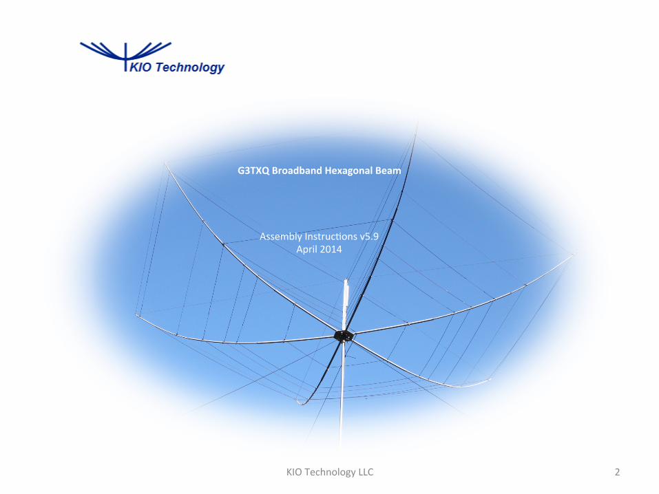
G3TXQ Broadband Hexagonal Beam
Assembly Instruc2ons v5.9 April 2014
2 KIO Technology LLC
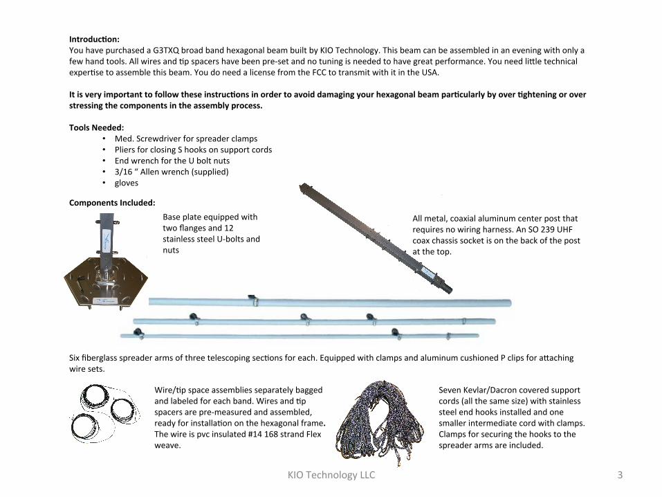
IntroducEon: You have purchased a G3TXQ broad band hexagonal beam built by KIO Technology. This beam can be assembled in an evening with only a few hand tools. All wires and 2p spacers have been pre-‐set and no tuning is needed to have great performance. You need lible technical exper2se to assemble this beam. You do need a license from the FCC to transmit with it in the USA. It is very important to follow these instrucEons in order to avoid damaging your hexagonal beam parEcularly by over Eghtening or over stressing the components in the assembly process. Tools Needed:
• Med. Screwdriver for spreader clamps • Pliers for closing S hooks on support cords • End wrench for the U bolt nuts • 3/16 “ Allen wrench (supplied) • gloves
Components Included:
!!
All metal, coaxial aluminum center post that requires no wiring harness. An SO 239 UHF coax chassis socket is on the back of the post at the top.
Base plate equipped with two flanges and 12 stainless steel U-‐bolts and nuts
Six fiberglass spreader arms of three telescoping sec2ons for each. Equipped with clamps and aluminum cushioned P clips for abaching wire sets.
Wire/2p space assemblies separately bagged and labeled for each band. Wires and 2p spacers are pre-‐measured and assembled, ready for installa2on on the hexagonal frame. The wire is pvc insulated #14 168 strand Flex weave.
Seven Kevlar/Dacron covered support cords (all the same size) with stainless steel end hooks installed and one smaller intermediate cord with clamps. Clamps for securing the hooks to the spreader arms are included.
3 KIO Technology LLC
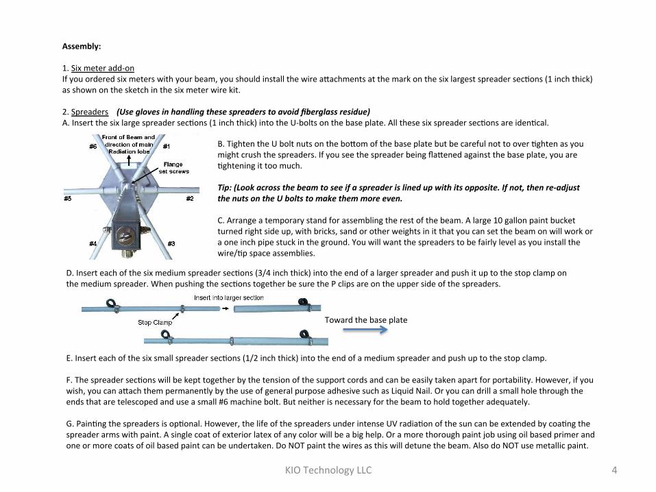
Assembly: 1. Six meter add-‐on If you ordered six meters with your beam, you should install the wire abachments at the mark on the six largest spreader sec2ons (1 inch thick) as shown on the sketch in the six meter wire kit. 2. Spreaders (Use gloves in handling these spreaders to avoid fiberglass residue) A. Insert the six large spreader sec2ons (1 inch thick) into the U-‐bolts on the base plate. All these six spreader sec2ons are iden2cal.
!
B. Tighten the U bolt nuts on the bobom of the base plate but be careful not to over 2ghten as you might crush the spreaders. If you see the spreader being flabened against the base plate, you are 2ghtening it too much. Tip: (Look across the beam to see if a spreader is lined up with its opposite. If not, then re-‐adjust the nuts on the U bolts to make them more even. C. Arrange a temporary stand for assembling the rest of the beam. A large 10 gallon paint bucket turned right side up, with bricks, sand or other weights in it that you can set the beam on will work or a one inch pipe stuck in the ground. You will want the spreaders to be fairly level as you install the wire/2p space assemblies.
!
!
D. Insert each of the six medium spreader sec2ons (3/4 inch thick) into the end of a larger spreader and push it up to the stop clamp on the medium spreader. When pushing the sec2ons together be sure the P clips are on the upper side of the spreaders.
Toward the base plate
E. Insert each of the six small spreader sec2ons (1/2 inch thick) into the end of a medium spreader and push up to the stop clamp. F. The spreader sec2ons will be kept together by the tension of the support cords and can be easily taken apart for portability. However, if you wish, you can abach them permanently by the use of general purpose adhesive such as Liquid Nail. Or you can drill a small hole through the ends that are telescoped and use a small #6 machine bolt. But neither is necessary for the beam to hold together adequately. G. Pain2ng the spreaders is op2onal. However, the life of the spreaders under intense UV radia2on of the sun can be extended by coa2ng the spreader arms with paint. A single coat of exterior latex of any color will be a big help. Or a more thorough paint job using oil based primer and one or more coats of oil based paint can be undertaken. Do NOT paint the wires as this will detune the beam. Also do NOT use metallic paint.
4 KIO Technology LLC

!
5 KIO Technology LLC
3. Center post Insert the center post into the base plate and turn it so that the white KIO logo label on the post is toward the KIO logo label on the base plate. This is the front of the beam and the direc2on of the main beam lobe. The coax will connect on the back of the center post and come down where it should be strapped to a spreader arm and then down the mast. Tighten the set screws on the flange using the 3/16” hex key supplied. Do not over 2ghten the center post. 4. Support Cords A. Hook a support cord to the end of a spreader and pull it toward the center post and let it lie on the ground loose. B. Hook another support cord to the end of the opposite spreader from Step 4.A. and pull it toward the center post. C. Now grip the loose ends of both support cords and pull them together un2l you can hook both over the eye bolt on the top of the center post at the same 2me. The idea of pulling two spreaders up at the same 2me is to avoid unnecessary stress on the center post. D. Repeat this with another pair of spreaders and support cords and then again un2l all six spreaders and support cords are abached to the center post. E. There are two remaining support cords. Hook the larger one between the ends of spreaders 1 and 6. The remaining small support cord will be abached later in Step 5 J. aler the wires have been installed. Dashed lines at right show the cords. The purpose of these two cords is to pull the spreaders arms 1 and 6 back into posi2on.
!
Spreader arms 1 and 6 are usually pulled too far apart by the weight and tension of the wires. When you first install this perimeter cord it will likely be too slack but it will 2ghten up later when the wires are installed. F. Fasten the hooks on the ends of the spreaders with the clamps supplied as shown to the lel.
To spreader
#1
To center post
Spreader #6

KIO Technology LLC 6
G. With pliers, squeeze all the hooks closed on the post top ring. You now have the basic hexagonal beam shape established. 5. Wire/Tip Spacer Assemblies A. Do not over Eghten the wires. The wires should be a lible slack. It is not necessary for the wires to be taut for the beam to perform as it is supposed to perform. B. Begin with the 10 meter Wire/Tip Spacer assembly (or the highest frequency band provided) and repeat for each of the bands with the lowest frequency band last. The lowest band will be the longest wire assembly. The wire/2p spacer assemblies are already adjusted exactly for each band and no adjustment of their length is required.
Tip: To keep them from gemng tangled up lay the wire assembly out along the ground unraveled and then start threading it through the abachment hardware carefully star2ng with spreader No 1. Shaking the wire can unravel a lot of tangles. It wants to come loose!
C. The 10 meter wire assembly uses the abachments nearest the center post unless six meters is provided in which case the six meter wire assembly uses the innermost abachments. D. When the assembly is pulled through the clamp abachments around all six spreaders you are ready to connect each of the two ends to the two terminals on opposite sides of the post marked 10M.
E. Pull the ends with the lugs in toward the center post and connect them to the bobom terminal. One end of the wire set connects to one side of the center post for that par2cular band and the other end of the wire set connects to the other side of the center post for that par2cular band.
If there is not enough slack to get the wire lugs on the terminals just loosen the clamps on Spreaders 1 and 6 and let them slip in toward the center post to allow you to make the terminal connec2ons.
!
DO NOT loosen the hex nuts that are already on the terminal bolts! These nuts are what hold the terminal bolts to the sides of the center post. If you loosen them, you might lose the terminal bolts as they might fall into the interior of the center post. Use the dome nuts supplied in the small bag abached to the center post to fasten the wire lugs to the terminal posts.
KIO Technology LLC 7
When 2ghtening the dome nuts be careful not to allow the bolt itself to twist. Use a small wrench or pliers to hold the hex nut while 2ghtening the dome nut as shown at right. Do not over 2ghten; just get it snug.
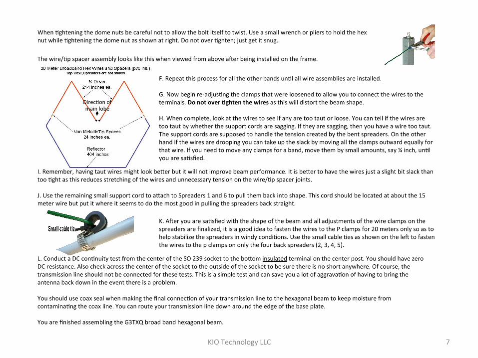
The wire/2p spacer assembly looks like this when viewed from above aler being installed on the frame.
!
F. Repeat this process for all the other bands un2l all wire assemblies are installed. G. Now begin re-‐adjus2ng the clamps that were loosened to allow you to connect the wires to the terminals. Do not over Eghten the wires as this will distort the beam shape. H. When complete, look at the wires to see if any are too taut or loose. You can tell if the wires are too taut by whether the support cords are sagging. If they are sagging, then you have a wire too taut. The support cords are supposed to handle the tension created by the bent spreaders. On the other hand if the wires are drooping you can take up the slack by moving all the clamps outward equally for that wire. If you need to move any clamps for a band, move them by small amounts, say ¼ inch, un2l you are sa2sfied.
I. Remember, having taut wires might look beber but it will not improve beam performance. It is beber to have the wires just a slight bit slack than too 2ght as this reduces stretching of the wires and unnecessary tension on the wire/2p spacer joints. J. Use the remaining small support cord to abach to Spreaders 1 and 6 to pull them back into shape. This cord should be located at about the 15 meter wire but put it where it seems to do the most good in pulling the spreaders back straight.
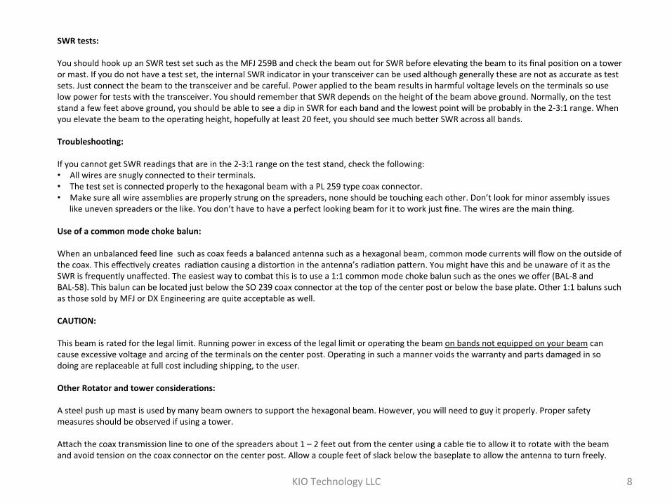
K. Aler you are sa2sfied with the shape of the beam and all adjustments of the wire clamps on the spreaders are finalized, it is a good idea to fasten the wires to the P clamps for 20 meters only so as to help stabilize the spreaders in windy condi2ons. Use the small cable 2es as shown on the lel to fasten the wires to the p clamps on only the four back spreaders (2, 3, 4, 5).
L. Conduct a DC con2nuity test from the center of the SO 239 socket to the bobom insulated terminal on the center post. You should have zero DC resistance. Also check across the center of the socket to the outside of the socket to be sure there is no short anywhere. Of course, the transmission line should not be connected for these tests. This is a simple test and can save you a lot of aggrava2on of having to bring the antenna back down in the event there is a problem. You should use coax seal when making the final connec2on of your transmission line to the hexagonal beam to keep moisture from contamina2ng the coax line. You can route your transmission line down around the edge of the base plate. You are finished assembling the G3TXQ broad band hexagonal beam.
Direc2on of main lobe
KIO Technology LLC 8
SWR tests: You should hook up an SWR test set such as the MFJ 259B and check the beam out for SWR before eleva2ng the beam to its final posi2on on a tower or mast. If you do not have a test set, the internal SWR indicator in your transceiver can be used although generally these are not as accurate as test sets. Just connect the beam to the transceiver and be careful. Power applied to the beam results in harmful voltage levels on the terminals so use low power for tests with the transceiver. You should remember that SWR depends on the height of the beam above ground. Normally, on the test stand a few feet above ground, you should be able to see a dip in SWR for each band and the lowest point will be probably in the 2-‐3:1 range. When you elevate the beam to the opera2ng height, hopefully at least 20 feet, you should see much beber SWR across all bands. TroubleshooEng: If you cannot get SWR readings that are in the 2-‐3:1 range on the test stand, check the following: • All wires are snugly connected to their terminals. • The test set is connected properly to the hexagonal beam with a PL 259 type coax connector. • Make sure all wire assemblies are properly strung on the spreaders, none should be touching each other. Don’t look for minor assembly issues
like uneven spreaders or the like. You don’t have to have a perfect looking beam for it to work just fine. The wires are the main thing. Use of a common mode choke balun: When an unbalanced feed line such as coax feeds a balanced antenna such as a hexagonal beam, common mode currents will flow on the outside of the coax. This effec2vely creates radia2on causing a distor2on in the antenna’s radia2on pabern. You might have this and be unaware of it as the SWR is frequently unaffected. The easiest way to combat this is to use a 1:1 common mode choke balun such as the ones we offer (BAL-‐8 and BAL-‐58). This balun can be located just below the SO 239 coax connector at the top of the center post or below the base plate. Other 1:1 baluns such as those sold by MFJ or DX Engineering are quite acceptable as well. CAUTION: This beam is rated for the legal limit. Running power in excess of the legal limit or opera2ng the beam on bands not equipped on your beam can cause excessive voltage and arcing of the terminals on the center post. Opera2ng in such a manner voids the warranty and parts damaged in so doing are replaceable at full cost including shipping, to the user. Other Rotator and tower consideraEons: A steel push up mast is used by many beam owners to support the hexagonal beam. However, you will need to guy it properly. Proper safety measures should be observed if using a tower. Abach the coax transmission line to one of the spreaders about 1 – 2 feet out from the center using a cable 2e to allow it to rotate with the beam and avoid tension on the coax connector on the center post. Allow a couple feet of slack below the baseplate to allow the antenna to turn freely.
KIO Technology LLC 9
! !
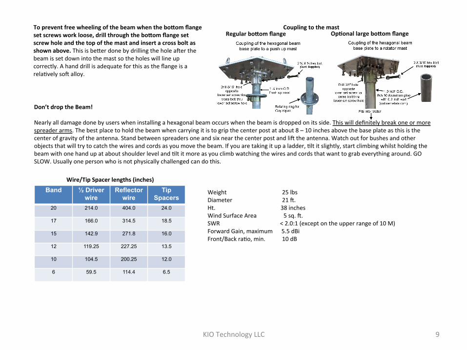
To prevent free wheeling of the beam when the boSom flange set screws work loose, drill through the boSom flange set screw hole and the top of the mast and insert a cross bolt as shown above. This is beber done by drilling the hole aler the beam is set down into the mast so the holes will line up correctly. A hand drill is adequate for this as the flange is a rela2vely sol alloy.
Regular boSom flange OpEonal large boSom flange Coupling to the mast
Don’t drop the Beam! Nearly all damage done by users when installing a hexagonal beam occurs when the beam is dropped on its side. This will definitely break one or more spreader arms. The best place to hold the beam when carrying it is to grip the center post at about 8 – 10 inches above the base plate as this is the center of gravity of the antenna. Stand between spreaders one and six near the center post and lil the antenna. Watch out for bushes and other objects that will try to catch the wires and cords as you move the beam. If you are taking it up a ladder, 2lt it slightly, start climbing whilst holding the beam with one hand up at about shoulder level and 2lt it more as you climb watching the wires and cords that want to grab everything around. GO SLOW. Usually one person who is not physically challenged can do this.
Band ½ Driver wire
Reflector wire
Tip Spacers
20 214.0 404.0 24.0
17 166.0 314.5 18.5
15 142.9 271.8 16.0
12 119.25 227.25 13.5
10 104.5 200.25 12.0
6 59.5 114.4 6.5
Wire/Tip Spacer lengths (inches)
Weight 25 lbs Diameter 21 l. Ht. 38 inches Wind Surface Area 5 sq. l. SWR < 2.0:1 (except on the upper range of 10 M) Forward Gain, maximum 5.5 dBi Front/Back ra2o, min. 10 dB


![Brych Technology LLC PRESENTATION [Recovered]](https://img.pdfslide.net/doc/110x75/5884b0291a28ab76798b6889/brych-technology-llc-presentation-recovered.jpg)