Embed Size (px)
Citation preview

Using KODAK EKTACOLOR Chemicals ● Z-130 05/11 1-1
1 KODAK EKTACOLOR ChemicalsKODAK EKTACOLOR Chemicals are designed for processing all Kodak color papers. This section describes the chemicals, lists the available sizes, and tells you how to mix and store them. It also gives simple methods of checking chemical mixes, and tells how to dispose of used chemicals properly and safely.
EKTACOLOR Chemicals can process the following papers and materials:• KODAK EKTACOLOR EDGE Paper
• KODAK ROYAL Digital Paper
• KODAK ROYAL Luminous Digital Paper
• KODAK Photo Book Paper
• KODAK PROFESSIONAL SUPRA ENDURA VC Digital Paper
• KODAK PROFESSIONAL ULTRA ENDURA Paper
• KODAK PROFESSIONAL ULTRA ENDURA High Definition Paper
• KODAK PROFESSIONAL ENDURA Metallic VC Paper
• KODAK PROFESSIONAL ENDURA Clear Display Material
• KODAK PROFESSIONAL ENDURA Transparency Display Material
Notes:1. For information on KODAK EKTACOLOR SM
Chemicals for Process RA-2SM, see KODAK Publication No. Z-101, Using KODAK SM Chemicals in SM Minilabs.
2. For Information on using the KODAK EKTACOLOR Processing Cartridge 111, for use in all models of Fuji Frontiers, and some models of Noritsu Digital Minilab equipment, using Processes CP-48S and CP-49E, see KODAK Publication No. CIS-229, Using the KODAK EKTACOLOR Processing Cartridge 111 with Digital Minilabs using Processes CP-48S and CP-49E.
3. For Information on KODAK EKTACOLOR Processing Cartridge 92/110, for use in KODAK PROFESSIONAL RP30 and SRP30 Laser Printers, see KODAK Publication Nos. CIS-239, Using the KODAK EKTACOLOR Processing Cartridge 92/110,CAT No. 1440775, for Professional Color Papers in KODAK PROFESSIONAL RP30 and SRP30 Laser Printers, and CIS-280, Using the KODAK EKTACOLOR Processing Cartridge 92/110,CAT No. 1440775, for Processing KODAK EKTACOLOR EDGE, ROYAL Digital, and KODAK PROFESSIONAL Pro Image II and PROFOTO Color Papers.
WHY USE KODAK CHEMICALS?The primary considerations when you choose photographic chemicals are—• quality of the results the chemicals produce
• availability, reliability, and expertise of the service you receive
• availability of the chemicals
• environmental impact of the chemicals
• chemical cost
In all of these factors, KODAK EKTACOLOR Chemicals are superior or competitive. Low replenishment rates not only lower your chemical costs; they mean less chemical mixing and lower labor costs. They also mean less environmental impact, because the volume of effluent is reduced.
KODAK EKTACOLOR Chemicals are readily available. And when you purchase KODAK Chemicals, you are supported by a reliable network of expertise: Kodak field representatives, the Kodak Information Center, Kodak Service and Support, Kodak Environmental Services, KODALINK Quality Management Software, and many helpful publications and other services.
Choosing the chemicals recommended in this publication ensures that you are using chemicals that provide optimum results with the smallest possible environmental impact.
KODAK EKTACOLOR Chemicals for Process RA-4 offer you these features and benefits:
FEATURES BENEFITS
• Fast access time • Quick processing of prints• Fast results from printer tests
• Low replenishment rates • Less chemical mixing• Less effluent discharged and
less environmental impact• Lower chemical cost
• Lower water usage • Low water and energy costs• Less effluent discharge
• Chemicals suitable for minilabs with a washless cycle
• Additional water and energy savings
• Lower effluent volume
• Process stability • Consistent, repeatable print quality over a broad range of processor utilizations
• Less need to adjust for low utilization
• Fewer printer changes due to process shifts
• Patented preservatives to protect developing agent from oxidation
• Stable developer activity
• Good mixes with a variety of water supplies
• Quality of local water supply not critical
• Stain-reducing agent • Clean, crisp whites in prints

1-2 Using KODAK EKTACOLOR Chemicals ● Z-130 05/11
WHAT KODAK EKTACOLOR CHEMICALS ARE AVAILABLE?KODAK EKTACOLOR Chemicals are available in a variety of sizes to meet the needs of any type of processing operation. Choose the sizes that are the most economical for you and that best meet your storage requirements.
The sizes listed in this publication are available in the U.S. and Canada; other regions may supply these chemicals in different sizes.
Chemicals for Large- and Medium-Volume Continuous ProcessorsThese large sizes of KODAK EKTACOLOR RA Chemicals enable high-volume labs to make fewer mixes. Mix the solutions according to the directions packaged with the chemicals.
KODAK EKTACOLOR RA Developer Replenisher 12This developer is designed specifically for continuous processors that have a utilization of at least one tank turnover per week. The developer time is the same as that recommended for EKTACOLOR RA Developer Replenisher; however, you must increase the developer temperature to 37.8°C (100.0°F).Available in a size to prepare 150 gallons (568 litres) of replenisher solution.
KODAK EKTACOLOR RA Developer Regenerator 12/55This regenerator enables you to collect and reuse overflow from EKTACOLOR RA Developer 12. With this regenerator, you do not need to use ion-exchange equipment. For information on using this regenerator, see Section 5, Processing Options with KODAK EKTACOLOR Chemicals.Available in a size to prepare 150 gallons (568 litres) of replenisher from developer overflow.
KODAK EKTACOLOR RA Developer ReplenisherUse this developer if your processor’s utilization is too low to use EKTACOLOR RA Developer Replenisher 12.Available in sizes to prepare 25 gallons (95 litres) and 75 gallons (284 litres) of replenisher solution.
KODAK EKTACOLOR RA Developer StarterUse this starter to prepare developer tank solution from EKTACOLOR RA Developer Replenisher, EKTACOLOR RA Developer Replenisher 12, EKTACOLOR PRIME SP Developer Replenisher LORR, EKTACOLOR RA Developer Replenisher RT, or EKTACOLOR Digital Developer Replenisher RT. Mix the solution according to the directions on the starter label. Available in an 80-ounce (2.366 litre) bottle to prepare 25 gallons (95 litres) of tank solution from EKTACOLOR RA Developer Replenisher or EKTACOLOR RA Developer Replenisher RT and EKTACOLOR Digital Developer Replenisher RT or 20.8 gallons (78 litres) from EKTACOLOR RA Developer Replenisher 12.
KODAK EKTACOLOR RA Bleach-Fix and Replenisher NRThis bleach-fix is designed for continuous processors with high utilization. It features a low replenishment rate.Available in sizes to prepare 20 gallons (76 litres) and 208 gallons (787 litres) of replenisher solution.
KODAK EKTACOLOR RA Bleach-Fix and ReplenisherUse this bleach-fix if your processor’s utilization is too low to use EKTACOLOR RA Bleach-Fix and Replenisher NR. Use as a replenisher or a tank solution.Available in a size to prepare 5 or 10 litres, or 25 gallons (95 litres) of solution.
KODAK EKTACOLOR RA Bleach-Fix Regenerator IIUse this bleach-fix for continuous processors withhigh utilization. (It is not recommended for use in roller transport processors.) After electrolytically desilvering the bleach-fix overflow, add this chemical to prepare the overflow for use as a replenisher. Regenerating the bleach-fix significantly reduces the BOD, COD, and iron in the effluent.Available in a size to prepare 100 gallons (378.5 litres) of replenisher solution from desilvered bleach-fix overflow.

Using KODAK EKTACOLOR Chemicals ● Z-130 05/11 1-3
Chemicals for MinilabsKODAK EKTACOLOR PRIME SP Developer Replenisher LORRThis developer replenisher is designed for minilabs with average to high utilization. Supplied as a single-part concentrate, it offers easy and convenient mixing and reduced replenishment rates.Available in sizes to prepare 10 litres and 10-gallon sizes of replenisher solution.
KODAK EKTACOLOR RA Developer StarterUse this starter to prepare developer tank solution. This starter will make 52.6 litres of tank solution from KODAK EKTACOLOR PRIME SP Developer Replenisher LORR or 95 litres of tank solution from EKTACOLOR RA Developer Replenisher RT, according to the direction on the starter label.
KODAK EKTACOLOR PRIME SP Bleach-Fix Replenisher LORRThis single-part bleach-fix replenisher is designed for minilabs with average to high utilization.You can use this bleach-fix if your processor has a tank turnover at least every four weeks. The replenishment rate is 75 percent lower than that of EKTACOLOR RA Bleach-Fix and Replenisher.Available in sizes to prepare 5 and 10 litres and 10 gallons (38 litres) of replenisher solution.
KODAK EKTACOLOR PRIME SP Bleach-Fix StarterTo make bleach-fix tank solution, mix this starter with KODAK EKTACOLOR PRIME SP Bleach-Fix Replenisher LORR according to the directions on the starter label. Makes 20 litres of tank solution.
KODAK EKTACOLOR PRIME Stabilizer and Replenisher LORRUse this stabilizer in place of a final wash in washless minilabs. Use as a replenisher or a tank solution.Available in sizes to prepare 5 and 10 litres and 12.5 gallons (47 litres) of replenisher solution.
KODAK EKTACOLOR RA Developer Replenisher RTIf your minilab is operating in low utilization conditions , use this developer replenisher. See Section 3, page 3, for details on utilization requirements.Available in sizes to prepare 10 litres and 25 gallons (95 litres) of replenisher solution.
KODAK EKTACOLOR RA Bleach-Fix and ReplenisherIf your minilab is operating in low utilization conditions, use this replenisher. See Section 3, page 3, for details on utilization requirements. Use as a replenisher or a tank solution.Available in sizes to prepare 10 litres and 25 gallons (95 litres) of solution.
Chemicals for Digital Printers / Processors Requiring CartridgesKODAK EKTACOLOR Processing Cartridge 92/110Use this cartridge in KODAK PROFESSIONAL RP 30 and SRP 30 Laser Printers. Each cartridge is mixed automatically and makes enough developer, bleach-fix, and stabilizer to process 92 square metres of professional paper (about 1770 8 x10-inch prints) or 110 square metres of EDGE or ROYAL Digital Paper (about 2120 8 x10-inch prints).
KODAK EKTACOLOR Processing Cartridge 111Use this cartridge on all models of the FUJI Frontier Digital Minilab. It is a drop-in product that requires no changes or modification to the equipment or existing chemistry. Simply load the cartridge and continue processing. Each cartridge provides enough developer and bleach-fix to process 111 square metres of paper, or about 7170 4 x 6-inch prints.
KODAK EKTACOLOR PC 111 Tank DeveloperUse this developer to prepare 4.2 litres of developer tank solution.
KODAK EKTACOLOR PC 111 Tank Bleach-FixUse this bleach-fix to prepare 4.2 litres of bleach-fix tank solution.
KODAK Rinse TabletsUse these tablets on all models of the FUJI Frontier Digital Minilab. This is a drop-in product that requires no changes or modification to the equipment or existing chemistry. Just place the tablet in the slot on the machine and mix with water. Each tablet will make 5 litres of final rinse.

1-4 Using KODAK EKTACOLOR Chemicals ● Z-130 05/11
Chemicals for Roller-Transport and Low-Utilization ProcessorsKODAK EKTACOLOR RA Developer Replenisher RTThis developer has built-in protection from oxidation and evaporation that makes it particularly suitable for roller-transport processors and continuous or minilab processors operating in low utilization conditions.Available in sizes to prepare 10 litres and 25 (95 litres) gallons of replenisher solution.
KODAK EKTACOLOR Digital Developer Replenisher RTThis developer is designed for commercial pro labs using Process RA-4. It produces increased color saturation and extra-high D-max (i.e., intense blacks) with KODAK PROFESSIONAL ENDURA Transparency and Clear Display Materials. It is primarily designed for digitally exposed output processed through roller-transport (RT) processors.
Available in sizes to prepare 50 gallons (189 litres) of replenisher solution.
KODAK EKTACOLOR RA Developer StarterAdd this concentrate to EKTACOLOR RA Developer Replenisher RT to prepare a developer solution for roller-transport processors.Available in an 80-ounce (2.366 litres) bottle to prepare 25 gallons (95 litres) of tank solution from EKTACOLOR RA Developer Replenisher RT and EKTACOLOR Digital Developer Replenisher RT.
KODAK EKTACOLOR RA Developer AdditiveIf your processor’s utilization is very low (requiring more than 8 weeks for a tank turnover), add this chemical to EKTACOLOR RA Developer Replenisher RT to provide additional protection from oxidation. Use this additive only with EKTACOLOR RA Developer Replenisher RT. Add this chemical only to the developer replenisher; do not add it directly to the developer working tank solution. Follow the directions on the bottle closely, because this additive requires a different dilution for the developer replenisher. Use the replenishment rates given in Section 4, Using KODAK EKTACOLOR RA Chemicals in Professional Finishing Labs; replenisher treated with this additive requires a different replenishment rate.Available in a case of six 48-ounce (1.42 litre) bottles. Each bottle makes 15.6 gallons (59 litres) of developer replenisher from a 12 1/2-gallon size.
KODAK EKTACOLOR RA Bleach-Fix and ReplenisherDilute and mix this concentrate for use as a replenisher or a tank solution.Available in sizes to prepare 5 litres, 10 litres, and 25 gallons (95 litres) of solution.
KODAK EKTACOLOR RA Beach-Fix AdditiveIf your processor utilization is very low, you can add this solution to EKTACOLOR RA Bleach-Fix and Replenisher for additional oxidation protection. Add this chemical only to the bleach-fix replenisher; do not add it directly to the bleach-fix working tank solution.Available in a case of six 48-ounce (1.42 litre) bottles.

Using KODAK EKTACOLOR Chemicals ● Z-130 05/11 1-5
CHEMICAL TERMSTo help you to understand the terms we’ve used to describe the chemicals in this manual, here are some definitions:
Chemical Concentrates—Chemicals that are diluted to make replenishers or tank solutions.
Fresh Solution—A newly mixed, unused solution.
Replenisher—Solution used to restore the chemical components of the tank solution to maintain photographic performance over time.
Regenerator—A solution or concentrate added to tank-solution overflow to convert it for reuse as a replenisher.
Seasoned Solution—A tank solution that has been used and replenished for a period of time. The chemical components and seasoning by-products of a seasoned solution are at an optimum level for processing.
Starter—Concentrate added to a replenisher to prepare a fresh tank solution so that it yields results similar to those provided by a seasoned tank solution.
Tank Solution—The solution used in the processor tank; often referred to as “working solution.”
MIXING CHEMICALSFor the most current mixing instructions, follow those on the label of the chemical container or packaged with the chemicals. Be sure to follow all safety precautions and the handling recommendations under Safe Handling of Photographic Chemicals.
Table 1-1 summarizes the mixing instructions for EKTACOLOR Chemicals.
Table 1-1 Mixing KODAK EKTACOLOR Chemicals
EKTACOLOR RA or EKTACOLOR Chemical Comments
Developer ReplenisherDeveloper Replenisher RTDigital Developer Replenisher RTDeveloper Replenisher 12
Mix at 21 to 38° C (70 to 100° F). The mixing order is important with developer replenishers because Part A contains the preservatives. Therefore, add Part B only after allowing Part Ato mix for at least two minutes, and add Part C only after allowing Part B to mix for at least two minutes. Failure to do so may result in the formation of precipitates that are very difficult to redissolve. Once the final kit parts are added, agitate enough to mix the developer completely, typically not more than 5 minutes, and be sure that mixing does not draw air into the solution.NOTE: Digital Developer Replenisher RT only has two parts, Part A and Part B.
Developer Regenerator 12/55 See Section 5, Processing Options with KODAK EKTACOLOR Chemicals, and the instructions packaged with the chemicals.
PRIME SP Developer Replenisher LORR Add the single-part concentrate to warm water (at 21 to 38° C [70 to 100° F]). Rinse the concentrate bottle with a small amount of water, and add the water to the mix.
Bleach-FixBleach-Fix and ReplenisherBleach-Fix and Replenisher NRPRIME SP Bleach-Fix and Replenisher LORR
Mix at 21 to 38° C (70 to 100° F). The chemicals mix easily. The bleach-fix and replenisher should be dark red when completely mixed.
Bleach-Fix Regenerator II See Section 5, Processing Options with KODAK EKTACOLOR Chemicals, and the instructions packaged with the chemicals.
PRIME Stabilizer and Replenisher LORR Mix at 21 to 35° C (70 to 95° F). Excessive agitation can cause foaming.

1-6 Using KODAK EKTACOLOR Chemicals ● Z-130 05/11
Contamination Can Ruin a ProcessTo minimize the possibility of contamination, keep processing and mixing equipment and storage containers clean. Dirt and contamination can affect the life and photographic quality of the processing solutions. Avoid conditions where solutions can come in contact with other chemicals. Contamination is most often caused by—• solution splashed or dripped into another solution
• using mixing equipment that has not been thoroughly cleaned
• dry chemicals that become airborne during mixing
• pipes and tanks made of material that reacts with the photographic chemicals
To reduce the possibility of contamination, take care to avoid dripping solution into other tanks when you remove racks for cleaning, avoid splashing by not agitating too vigorously, and check that processing and mixing equipment and plumbing are made of suitable material. If possible, use a separate set of mixing equipment to mix each type of solution, and wash all equipment thoroughly before you reuse it.
Using separate mixing tanks may not always be practical or possible. Table 1-2 gives mixing arrangements for one to four mixing tanks. Use it as a guide for using your mixing tanks in the best manner to reduce the possibility of contamination.• If you mix only chemicals for NEGATIVE processes, use
two mix tanks: one for developer and one for all other solutions.
• If you mix chemicals for NEGATIVE and REVERSAL processes, use four mix tanks: one for the negative developer and the reversal first developer; one for color developer; one for bleach and bleach-fix; and one for all other solutions.
Remember also that good housekeeping (e.g., keeping the mixing area clean, neat, and well ventilated; proper storage of chemicals, etc.) will reduce the possibility of contamination and provide safer working conditions.
Table 1-2 Configurations for Chemcial Mixing Tanks
If you have ONE tank:
Reduce the chance of chemical contamination by using four separate mixing tanks. If you cannot use four separate tanks, do the following before mixing different batches of chemicals:
• Thoroughly rinse the tank and mixing equipment with room-temperature water
• Flush tubing and lines• Thoroughly clean transfer pumps
If you have TWO tanks:
Use the FIRST tank for:
• Black-and-white developers• First developer for Process E-6• Color developer for Process RA-4 and C-41, and for Process
E-6 Color Developer
Use the SECOND tank for:
• All stop baths and stabilizers• Reversal bath, pre-bleach, and final rinse for Process E-6• All bleaches, fixers and bleach-fixes• Final rinse for Process C-41
If you have THREE tanks:
Use the FIRST tank for:
• Black-and-white developers• First developer for Process E-6• Color developer for Process RA-4 and C-41, and for Process
E-6 Color Developer
Use the SECOND tank for:
• All stop baths and stabilizers• Reversal bath, pre-bleach, and final rinse for Process E-6• Final rinse for Process C-41
Use the THIRD tank for:
• All bleaches, fixers, and bleach-fixers
If you have FOUR tanks:
Use the FIRST tank for:
• Black-and-white developers• First developer for Process E-6
Use the SECOND tank for:
• Color developer for Process RA-4 and C-41, and for Process E-6 Color Developer
Use the THIRD tank for:
• Stop baths and stabilizers• Reversal bath, pre-bleach, and final rinse for Process E-6• Final rinse for Process C-41
Use the FOURTH tank for:
• All bleaches, fixers, and bleach-fixers

Using KODAK EKTACOLOR Chemicals ● Z-130 05/11 1-7
Water QualityWater can have a significant effect on photographic quality. Generally, most municipal or public water supplies are sufficiently pure for photographic use. Note that the quality of water supplies can vary seasonally, and it is a good idea to have your water supply tested periodically.
Water for photographic processing should be free of color, suspended material, and heavy metals, and should not be excessively hard. For mixing processing solutions, the water should have less than 250 ppm of total dissolved solids (less than 1000 ppm for wash water). The pH of water should be 6.5 to 8.5 and should not be highly buffered. Practical limits for common water impurities for photographic processing are listed in Table 1-3. If you use well water, be sure to have the water tested for the impurities listed in Table 1-3.
Also, poor plumbing materials (e.g., old, rusty pipes or pipes made of the wrong material) can be a source of dirt and contamination. Check your plumbing and replace it if necessary.
Table 1-3 Practical Limits of Impurities for Water Used in Photographic Processing
Note: If analysis of water shows a marked deviation from the amounts in Table 1-3, consult a water-conditioning company to determine the most suitable method of treatment or filtration of the water.
Impurity Acceptable Limit or Range (ppm)
Color, suspended material None
Dissolved solids 250
pH 6.5 to 8.5
Hardness, as CaCO3 40 (preferable) to 150
Copper, iron, manganese 0.10 each
Chlorine, as free hypochlorus acid 2
Chloride 100
Bicarbonate 150
Sulfate 200
Sulfide 0.10
Silica 20.0
Construction Materials for Processing EquipmentIt is important to use the proper construction materials for processing equipment.
Developers—Use Type 316 stainless-steel tanks for developers. Some plastic materials, such as PVC and polyethylene, are also acceptable.
Bleach-Fix—Bleach-fix rapidly corrodes brass and copper. Avoid all contact of these materials with the bleach-fix. The best material to use for the bleach-fix and the wash tanks following the bleach-fix is Type 316 stainless steel. Several plastic materials, such as PVC and polyethylene, are also acceptable. When you discharge bleach-fix to the drain, flush it with a large volume of running water to avoid corroding metal pipes.
Clean Your Processor Tanks and Racks RegularlyAlways wear splash-proof goggles and protective gloves and apron when you clean racks and tanks.
Routine Cleaning—Follow the recommendations described below. Be sure to follow your equipment manufacturer’s recommendations for regular maintenance procedures.
1. Remove crossovers, squeegee rollers, or squeegees daily at shutdown, and rinse them with hot water.
2. Once a week, remove each rack from the processor, clean it with hot water and a soft, non-abrasive brush, and rinse thoroughly. Inspect the racks for non-moving rollers, deformities in rollers, worn or broken springs, loose screws, deteriorated retaining clips, etc., to ensure smooth transport of paper.
3. On a periodic basis (every 6 to 12 months), clean racks and tanks with a non-abrasive brush, and remove stains from racks and tank walls with a cleaner such as KODAK Developer System Cleaner and Neutralizer for developer tanks and KODAK Fixer/Wash Systems Cleaner for bleach-fix, fixer and wash tanks (follow the instructions provided with these products). Rinse racks and tanks thoroughly before you refill the tanks.

1-8 Using KODAK EKTACOLOR Chemicals ● Z-130 05/11
Removing Biological Growth—Biological growth can occur in stabilizer and wash tanks. This is a potential source of dirt. Clean wash tanks weekly and stabilizer tanks as needed. To remove biological growth:
1. Empty the processing solution or wash water from the tank. Dispose of waste solutions according to disposal regulations.
2. Rinse the tanks and racks with hot water; drain the rinse water and repeat.
DANGER! The addition of cleaning agents that contain strong acids or oxidizing agents (e.g., chlorine-containing bleaches) to thiocyanate-containing photoprocessing solutions (i.e., some fixer solutions) may release poisonous and flammable hydrogen cyanide gas, as well as other irritating and toxic gases, such as cyanogen chloride and sulfur dioxide. Do not add cleaning agents to processing tanks unless the tanks, racks, and recirculation system have been completely drained and thoroughly flushed and rinsed with water. Read the Material Safety Data Sheet for information on the potential hazards of the working tank solution.
3. Fill the tanks with sodium hypochlorite (NaOCl) solution, such as 2 mL Clorox (5.25 percent NaOCl) or 1 mL Sunny Sol (12.5 percent NaOCl) per litre of water. (Note the caution above.)
4. Allow the hypochlorite solution to remain in the tanks for up to 30 minutes. Longer dwell times can damage plastic or rubber materials. After treatment, dispose of the hypochlorite solution according to local or state disposal regulations.
5. Brush foreign matter from the tanks and racks.
6. Before refilling the tanks, flush them thoroughly with water. Small amounts of remaining hypochlorite can have an adverse effect on processing solution activity. Be sure to recirculate rinse water through the recirculation system to remove traces of hypochlorite.
Note: For more information on the recommended methods for cleaning processing tanks, in the U.S., contact the Kodak Information Center at 866-352-4367. In Canada, call 800-465-6325. In other regions, contact Kodak in your country. For information on controlling biological growth, go to www.kodak.com/go/photochemicals for KODAK Publications CIS-3, Biocides for Photographic Solution Tanks and Wash Water and CIS-167, Removal of Silver Sulfide from Fixer, Bleach-Fix, Wash or Stabilizer Racks/Rollers in Photographic Processes.

Using KODAK EKTACOLOR Chemicals ● Z-130 05/11 1-9
CHECKING CHEMICALS AND CHEMICAL MIXESFresh EKTACOLOR Chemical concentrates and solutions have a characteristic appearance and odor. By checking the appearance and odor, you may be able to determine if a concentrate was stored properly or if a solution was mixed correctly. Table 1-4 summarizes the characteristics of EKTACOLOR Chemicals and solutions. You can check your mixes for possible mixing errors by using specific-gravity measurements. For information on making specific-gravity measurements, see Check Your Mixes with Specific-Gravity Measurements.
Table 1-4 Characteristics of KODAK EKTACOLOR Chemicals
EKTACOLOR Chemical Appearance of Concentrates Normal Appearance of Mixed Replenisher Comments
Developer
Developer Replenisher RT
Developer Replenisher 12
Part A — clear, yellow to reddish amber; amine odorPart B — Clear amber to tan;sulfite odorPart C — Clear, colorless; odorless
Pale yellow to amber Darkens slightly with age/storage, this will not affect activity. If appearance of Part B concentrate is dark, opaque, solution is oxidized, do not use.If appearance of mixed replenisher is dark, opaque, it is oxidized, do not use.
Digital Developer Replenisher RT
Part A — clear, amber to reddish amber; amine odorPart B — Clear to yellow
Pale yellow to amber Darkens slightly with age/storage, this will not affect activity. If appearance of Part A concentrate is dark, opaque, solution is oxidized, do not use.If mixed replenisher is dark, opaque, it is oxidized, or if precipitate is present, do not use.
PRIME SP Developer Replenisher LORR
Clear, yellow-amber to orange; fresh odor
Pale amber to amber Appearance of concentrate can darken slightly with age/storage, this will not affect activity. If the appearance of the concentrate or mixed replenisher is dark, opaque, solution is oxidized, do not use.
Developer Starter Clear, colorless; odorless — —
Bleach-Fix Replenisher Part A — Clear, colorless, slight ammonia odorPart B — Dark red-brown
Dark red-brown Do not allow concentrate to freeze, as precipitate may form.Age, exposure to high temperature, or oxidation can cause sulfurization of Part A or of mixed replenisher. Severely degraded bleach-fixes can produce a large amount of white to yellow precipitate (sulphur) and may have a hydrogen sulfide odor. (i.e., rotten egg odor).
PRIME SP Bleach-Fix and Replenisher LORR
Dark red-brown, slight acetic acid odor
Dark red-brown
PRIME SP Bleach-Fix Starter
Dark red-brown — —
PRIME Stabilizer and Replenisher LORR
Clear, colorless to pale green Clear, colorless —

1-10 Using KODAK EKTACOLOR Chemicals ● Z-130 05/11
Check Your Mixes with Specific-Gravity MeasurementsSpecific gravity is the ratio of the mass of a liquid to the mass of an equal volume of water at a specific temperature. Specific gravity provides a convenient way to measure the total dissolved material in a solution. Its primary use with EKTACOLOR Chemicals is to check for mixing errors in freshly mixed solutions. The specific-gravity range for a seasoned tank solution makes readings more variable.
How to Measure Specific Gravity—To make specific-gravity measurements of EKTACOLOR Chemicals, use a hydrometer that meets the standard ASTM E100-05. The hydrometer should be marked in increments of 0.001 for an accuracy of ± 0.0005. Although most hydrometers are calibrated at 15.5°C (60°F), you can use them at other temperatures. Table 1-5 gives typical specific-gravity ranges for fresh mixes and seasoned tank soltutions of KODAK EKTACOLOR Chemicals at a temperature of 25°C (77°F). To measure specific gravity:1. Choose a hydrometer with a range suitable for the solution you are measuring.
2. Fill a clean, dry 250 mL graduated cylinder to within 2.5 cm (1 inch) of the top with the solution you are measuring. Place the cylinder in a sink or tray to catch overflow.
3. Adjust the solution to 25.0 ± 1°C (77 ± 2°F). Proper solution temperature is very important.
4. Be sure that the hydrometer is clean and dry. Carefully lower it into the solution. Be sure that the hydrometer floats freely.
5. Read the number on the hydrometer stem at the top of the meniscus of the solution.
6. Compare your reading with the approximate number in Table 1-5. Specific-gravity values that are lower than normal indicate that your solution is too dilute. If the values are higher than normal, your solution is too concentrated.
7. After making the measurement, discard the sample. To avoid contaminating solutions, do not return the sample to the tank.
8. Rinse the hydrometer and graduated cylinder thoroughly with water.
Note: Never take specific-gravity readings of solutions in the tanks. If you use the wrong hydrometer, it can sink to the bottom of the tank and break, or bob on the surface, where the stem may hit the edge of the tank and break. Label hydrometer boxes to avoid confusion. Do not tape labels on hydrometers.
Table 1-5 Acceptable Specific-Gravity Ranges for KODAK EKTACOLOR Chemical Solutions at 25°C (77°F)
KODAK EKTACOLOR ChemicalSpecific Gravity at 25° C (77° F)
Fresh Tank Seasoned Tank Replenisher
Developer 1.017 to 1.023 1.027 to 1.035 1.024 to 1.030
RA 12 Developer Replenisher 1.019 to 1.025 1.028 to 1.036 1.022 to 1.028
RA 12/55 Regenerator NA 1.032 to 1.040 1.029 to 1.037
RA Developer Replenisher RT 1.017 to 1.023 1.026 to 1.034 1.020 to 1.026
Digital Developer Replenisher RT 1.022 to 1.028 1.027 to 1.035 1.027 to 1.033
RA Developer Replenisher RT (with Additive) NA NA 1.018 to 1.024
PRIME SP Developer LORR 1.018 to 1.028 1.027 to 1.035 1.023 to 1.031
Processing Cartridge PC 92/110 Developer 1.030 to 1.036 1.032 to 1.042 1.034 to 1.042
Processing Cartridge PC111 Developer NA 1.039 to 1.047 1.041 to 1.049
RA Bleach-Fix NR 1.060 to 1.070 1.080 to 1.110 1.125 to 1.135
RA Bleach-Fix 1.070 to 1.080 1.066 to 1.096 1.070 to 1.080
Processing Cartridge PC 92/110 Bleach-Fix — 1.090 to 1.120 1.113 to 1.123
Processing Cartridge PC111 Bleach-Fix NA 1.090 to 1.120 NA

Using KODAK EKTACOLOR Chemicals ● Z-130 05/11 1-11
STORING CHEMICAL CONCENTRATES AND SOLUTIONSHow well you store chemical concentrates and solutions may affect the activity of processing solutions. For the most up-to-date source of information on mixing and storing chemicals, see the instructions packaged with the chemicals.
Storage Temperature—Store unmixed chemical concentrates in a dry location at a temperature of 7 to 30°C (45 to 86°F). Lower temperatures may cause components to come out of solution or crystallize. Higher temperatures can accelerate chemical reactions and cause deterioration.
Store mixed solutions in polyethylene storage tanks at approximately 21°C (70°F). If a replenisher is stored at a temperature that is too low, it can affect the temperature of the tank solution. Too high a storage temperature accelerates oxidation and evaporation.
Storage Tanks and Containers—Equip storage tanks with floating lids and dust covers to minimize evaporation and protect solutions from dust and dirt.
Once you open the original container, the chemical concentrates are exposed to oxygen that will react with the chemicals and gradually cause them to deteriorate. This is especially true of developers. Oxidation occurs to some extent even if you immediately reseal the container.
Store drums upright to expose as little surface area to the air as possible.
Length of Storage Time—For best results, do not use solutions stored longer than the times given in Table 1-6.
Table 1-6 Solution Storage Times
Mixed Solutions
Solution in Processor–
No Operation
Replenisher in Covered Tank with
Floating Lid
EKTACOLOR RA DeveloperEKTACOLOR RA Developer RT 1 week 6 weeks
EKTACOLOR Developer 12EKTACOLOR RA Developer Regenerator 12/55
1 week 3 weeks
EKTACOLOR PRIME SP Developer LORR 1 week 3 weeks
All other solutions 2 weeks 8 weeks
SAFE HANDLING OF PHOTOGRAPHIC CHEMICALSEvery substance we come into contact with is composed of chemicals-the food we eat, the air we breathe, the clothing we wear, the medicine we take. Although most of these chemicals are not hazardous, you may need to take precautions to limit the exposure to some chemicals that could be harmful. For example, direct skin or eye contact with or inhalation of vapors or mists from some household cleaning products can be irritating.
When handled properly, photographic processing chemicals are safe to use. Follow the guidelines below to minimize the potential hazardous effects of these chemicals.
Be InformedSafe handling of chemicals requires that you recognize and avoid the potential hazards. Learning more about photographic processing chemicals reduces the possibility of illness or injury.
Occupational Health and Safety RegulationsThe Occupational Safety and Health Administration (OSHA) Hazard Communication Standard requires chemical manufacturers to label their products properly and to provide Material Safety Data Sheets (MSDSs) for hazardous chemicals. OSHA also requires employers to make MSDSs available in the workplace for the purpose of proper chemical container labeling, and to train employees on the safe use of chemicals. Local emergency responders may also require MSDS's to be on hand.
Product LabelsKodak provides warning and precautionary statements on product labels, instruction sheets, and packaged products. Kodak also provides labels for processor and replenisher tanks. Kodak evaluates photographic processing chemicals for potential health and physical hazards. When a photographic processing chemical has little, if any, potential hazard, the statement "LOW HAZARD FOR RECOMMENDED HANDLING" is included on the label.Photographic processing chemicals that are potentially hazardous have appropriate precautionary statements, such as the following:
Signal Word-For example, "CAUTION," "WARNING," or "DANGER!"
Statement of Hazard-For example, "CAUSES SKIN AND EYE BURNS," "HARMFUL IF ABSORBED THROUGH THE SKIN," or "FLAMMABLE."
Precautionary Wording-For example, "Do not get in eyes, on skin, or on clothing" or "Keep away from heat, sparks, and flame."
First-Aid Statements-Included on labels and signs to describe immediate measures you must take in case of contact with or overexposure to a photographic processing chemical.

1-12 Using KODAK EKTACOLOR Chemicals ● Z-130 05/11
Material Safety Data SheetsPhotographic processing facilities are required by OSHA to have MSDSs for all hazardous chemicals. MSDSs provide detailed information about each product. Information included in MSDSs is outlined in the following categories: chemical and manufacturer identification; composition/ingredients; hazard identification; first-aid measures; fire-fighting measures; accidental release measures; handling and storage; exposure controls and personal protection; physical and chemical properties; stability and reactivity; toxicological information; ecological issues; disposal issues; transport issues; regulatory issues; and other information.
Kodak provides customers with MSDSs for all photographic processing chemicals. If you need replacement(s) or extra MSDSs for any Kodak chemical, visit the Kodak website at www.kodak.com/go/MSDS or call 1 800 242 2424. You will need to supply the catalog (CAT) number of the products for which you need MSDSs.
TrainingOSHA requires that all employees be trained on the safe handling of photographic processing chemicals and general lab safety prior to their initial assignment and whenever new hazards are introduced into the workplace. Employees should be familiar with the OSHA Hazard Communication Standard, operations where hazardous chemicals are present, the location and content of Material Safety Data Sheets, physical and health hazards of chemicals in their work area, and additional topics. For more information on OSHA's Hazard Communication Standard, see KODAK Publication No. J-311, Hazard Communication for Photographic Processing Facilities. You may also want to review KODAK Publication No. J-98R, Health, Safety, and Environmental Program.
Handle Chemicals ProperlyOnce you know the hazards, learn how to handle chemicals safely. Safe handling practices include wearing personal protective equipment, following procedures that minimize chemical contact, and following the instructions on chemical labels. If contact occurs, know how to treat or obtain medical/first-aid assistance.
Protective Equipment and ClothingOSHA requires that personal protective equipment (PPE) be used in the workplace whenever the possibility of chemical contact exists. OSHA also requires that you perform a hazard assessment in your facility to determine what type of personal protective equipment is required to protect against the hazards present. In general, the personal protective equipment required for handling photographic processing chemicals includes:• Neoprene or nitrile gloves
• Safety goggles
• Vinyl or rubber apron or lab coat
Check personal protective equipment often to make sure it is in good working condition, is clean, and works and fits properly. Training must be provided on the use, limitations, and maintenance of personal protective equipment. For more information, see KODAK Publication No. J-312, Personal Protective Equipment Requirements for Photographic Processing Facilities.
Corrosive MaterialsCertain photographic processing chemicals contain materials that can burn or irritate the skin and eyes, sometimes with only brief contact. To reduce the possibility of injury, always wear personal protective equipment when handling photographic processing chemicals. Also make sure an emergency eyewash station is readily available.
Contact DermatitisDermatitis is the medical term used to describe a skin inflammation. Contact with some materials, such as acids and bases, can cause irritative contact dermatitis, while other chemicals, such as photographic developers, may cause allergic contact dermatitis.
Early symptoms of irritative contact dermatitis may include dry, red, cracked, or scaly skin at the site of contact. Symptoms may worsen with continued chemical exposure. In most cases of allergic contact dermatitis, the symptoms are itchy blisters similar to those seen from exposure to poison ivy or poison oak. Although the rash is usually confined to the site of contact, most often fingers, hands, and forearms, it may spread to other areas.
Sometimes people can work with a chemical for years without any noticeable effect, only to develop contact dermatitis at a later date. The time between contact and when a response develops varies widely among individuals. People with a history of skin allergies, eczema, or other skin disorders may be more susceptible to the effects of contact with chemicals.
If you think you have developed contact dermatitis, contact your manager. A medical examination may be required to determine the cause of the problem. Do not attempt to self-medicate with lotions or creams; they may make the problem worse.
Using KODAK EKTACOLOR Chemicals ● Z-130 05/11 1-13
To prevent contact dermatitis when handling photographic processing chemicals, follow these guidelines:• Read the labels on chemical containers so that you know
what precautions to take when handling the contents.
• Avoid contact with chemicals whenever possible. Handle chemical solutions carefully to avoid splashing. Keep all personal protective equipment (gloves, goggles, apron, etc.) free of chemical residues.
• Wear the proper gloves. Do not use gloves sold for household use; they may not be durable enough for handling photographic processing chemicals. Neoprene or nitrile gloves protect you from photographic processing chemicals. To minimize the possibility of chemicals coming in contact with your bare hands, rinse gloves thoroughly with water before taking them off. On a regular basis or if chemicals get inside the gloves, wash them inside and out, and hang them by the fingertips to dry.
– Check gloves regularly for pinholes, leaks, or tears.
– Dispose of gloves when they are damaged or begin to degrade.
– Barrier creams ARE NOT an acceptable substitute for gloves.
• In case of contact with chemicals, wash your hands or other affected skin areas immediately with plenty of water. Wash with a mild soap or pH-balanced cleanser (like pHhisoderm or pHotoDerm). Avoid using harsh or abrasive soaps or hand cleaners.
• Protect skin abrasions or cuts. The risk of contact dermatitis is increased if chemicals penetrate the skin. Skin damaged by cuts or abrasions is especially susceptible to irritants.
• Change and launder clothing worn while handling chemicals. If photographic processing chemicals are splashed or spilled on your clothes, immediately rinse the clothes to remove the chemical residue. Wash contaminated clothing before wearing it again.
• Clean up chemical spills or splashes immediately. Always wear personal protective equipment when cleaning up spilled photographic processing chemicals. Follow the directions under "Accidental Release Measures" in the MSDS. To prevent a potentially dangerous chemical reaction, never use soaps, bleaches, or other cleaners directly on a spill.
• Immediately report any unusual skin condition that you think might be related to photographic processing chemicals to your manager and to your physician. Conditions such as contact dermatitis can be caused by materials other than photographic processing chemicals; dermatitis usually will not improve until the cause is found and the condition is properly treated.
Absorption of Chemicals Through the SkinSome chemicals are able to enter the body by absorption through the skin. A variety of factors determines the effects of these chemicals, including the toxicity of the chemical, its concentration, and the duration of skin contact. Chemicals can have a toxic effect even without skin irritation. If tests indicate that a photographic processing chemical may be absorbed through the skin in amounts that could cause an adverse effect, the product label will include a precautionary statement, such as "HARMFUL IF ABSORBED THROUGH THE SKIN." Always wear personal protective equipment when handling these chemicals.
VentilationProper ventilation is important to ensure a safe and comfortable indoor air environment for photographic processing areas. Several common potential indoor air contaminants can be associated with photographic processing. These include acetic acid, sulfur dioxide, and ammonia. These chemicals may be eye and respiratory tract irritants depending on their airborne concentrations. OSHA and other agencies have established exposure guidelines and standards that represent concentrations under which it is believed that nearly all employees may be repeatedly exposed to these chemicals without adverse health effects. If significant eye or respiratory tract irritation occurs during normal photographic processing or maintenance operations, this may indicate elevated levels of these materials and the need for better control.
For more information, see KODAK Publication No. J 314, Indoor Air Quality and Ventilation in Photographic Processing Facilities.
Photographic Chemicals in a Home DarkroomPhotographic chemicals used in home darkrooms are essentially the same as those used in commercial photoprocessing labs, but they are used in smaller volumes and less frequently. The safety precautions are the same as those required for commercial labs. However, it is important to take extra precautions for storage and use to protect young children and pets.

1-14 Using KODAK EKTACOLOR Chemicals ● Z-130 05/11
Know First Aid in Case of an EmergencyAppropriate first-aid treatment is included in the MSDS and on the product and processor labels. First aid should be used for immediate treatment in the event of an emergency and is not intended to replace medical attention. Do not administer first aid to others unless you have been specifically trained to do so.
Chemical SplashesIf a chemical gets into a person's eye(s), use an eyewash station to thoroughly flush the eye(s). Get medical attention, if necessary.
If you get chemicals on your clothing, thoroughly rinse the affected clothes to remove all of the chemical residue. Use water to rinse the skin area where the chemical contact took place. If the chemical is a developer, wash with a pH-balanced cleanser. Wash contaminated clothing before wearing it again. Thoroughly clean contaminated shoes; if they cannot be cleaned, discard them.
Swallowed ChemicalsImmediately identify which chemical was swallowed and follow the first-aid recommendations on the container/processor label and in the MSDS. Call a physician or poison-control center as quickly as possible; make sure you have the MSDS with you when you call.
Inhaled Vapors and GasesImmediately get fresh air. If symptoms persists, get medical attention.
Store Chemicals SafelyKeep containers easily accessible-Always store photographic processing chemical containers in a designated area, away from heavy traffic, where they can be identified and inventoried. Position containers in an area where you can easily reach them without having to stretch.
Do not remove chemical labels-Container labels include the chemical name, appropriate hazard warnings, and precautionary measures where applicable.
Processor tanks and other storage tanks also need to be properly labeled. Kodak provides hazard warning labels for this purpose.
Use the proper containers-Store photographic processing concentrates in the containers in which they were originally delivered. Do not transfer chemicals into any other containers.
Keep corrosive materials separated-Store corrosive materials away from any materials with which they may react, and away from other incompatible materials. See the stability and reactivity section on the MSDS for more information.
Dispose of Photographic Chemicals ProperlyAlways follow the procedures designated for your photographic processing facility when disposing of photographic processing chemicals. These disposal procedures are based on local, state, and federal requirements that regulate the disposal of photographic processing chemicals.
If your facility discharges waste solutions, make sure you have reviewed the local sewer discharge requirements for your area. Use silver-recovery methods for silver-bearing effluents (e.g., used fixers, bleach-fixes, and stabilizers). Also, know what other materials may be discharged to a common drain. Never pour any photographic processing chemicals into a drain where cleaning agents containing chlorine are present unless the drain has been thoroughly rinsed. Run plenty of water down the drain prior to disposing of photographic processing chemical effluents. Then thoroughly rinse the drain again after disposal of effluents.
For more information on silver recovery, see KODAK Publication No. J 212, The Technology of Silver Recovery for Photographic Processing Facilities.
If off-site treatment (hauling) is used for the disposal of waste photographic processing solutions, make sure the only solutions poured into the waste drum(s) are photographic processing solutions.
Regardless of the type of recovery or disposal procedure you use in your facility, maintain the system so that overflows and spills do not occur.
SummarySafe handling of photographic chemicals is easy when you use common sense and follow these guidelines:• Know the chemicals you are handling.
• Read the MSDSs and container labels.
• Protect your eyes and skin by wearing personal protective equipment.
• Use caution when mixing and pouring photographic processing chemical solutions into processor tanks.
• Use care when moving containers from one location to another.
• Store photographic processing chemicals safely.
• Do not eat, drink, or smoke in chemical-handling areas.

Using KODAK EKTACOLOR Chemicals ● Z-130 05/11 1-15
EFFLUENT DISPOSALEffluent from processing labs that use KODAK EKTACOLOR Chemicals consists of developer, desilvered bleach-fix, and wastewater or stabilizer. This effluent is compatible with and can be effectively treated by a municipal secondary wash-water treatment plant.
Photographic effluent is considered an industrial waste discharge. Most municipalities require a permit to discharge industrial waste to a municipal sewer system. After efficient silver recovery, the effluent from a lab using Process RA-4 has the characteristics listed in Table 1-7.
Table 1-7 Effluent Characteristics
Effluent from processes that use EKTACOLOR Chemicals will also contain concentrations of ammonia, iron, sulfates, developing agents, and chemicals that have an oxygen demand (BOD, COD). The concentrations of these chemicals will depend on factors such as replenishment and wash rates, type of processor, efficiency of squeegees, chemical regeneration, treatment methods, and dilution by effluent from other processes and non-processing wastewater. To characterize waste from your processing operation, it is best to have the effluent sampled by an analytical laboratory according to the method required by local discharge codes.
Keep the discharge of photographic chemicals as low as possible by using efficient squeegees and the correct replenishment rates. Avoid making batch discharges, such as tank dumps. If your permit allows, discharge large amounts of working-strength solutions by adjusting the pH and then releasing them slowly into the sewer along with your normal non-processing effluent.
Consider silver recovery as part of your normal processing operation. For more information on choosing a silver-recovery method, see KODAK Publication No. J-212, The Technology of Silver Recovery for Photographic Processing Facilities. For more information on how much silver can be recovered, see KODAK Publication No. J-210, Sources of Silver in Photographic Processing Facilities. For more information on techniques for measuring silver in a photographic processing lab, see KODAK Publication No. J-211, Measuring Silver in Photographic Processing Facilities.
If you have other questions about discharging EKTACOLOR Chemicals or other environmental concerns, in the U.S., call the Kodak Information Center at 800-242-2424. In Canada, call 800-465-6325. In other regions, contact Kodak in your country.
pH 6.5 to 9
Temperature Less than 30°C (90°F)
Silver Less than 5 mg/L
Suspended solids Less than 50 mg/L
Oils, greases, detergents None
Flammable, explosive, or toxic materials None
MORE INFORMATIONFor general questions regarding health, safety, disposal of chemicals, or other environmental issues, in the U.S., call the Kodak Information Center at 800-242-2424. In Canada, call 800-465-6325. In other regions, contact Kodak in your country.
For emergency health or safety information, call 585-722-5151. For non-emergency information, go to www.kodak.com/go/kes for the MSDS.
For questions concerning the safe transportation of Kodak products, call Kodak Transportation Services at 585-722-2400, between 8 a.m. and 5 p.m. (Eastern time).
The products and services described in this publication may not be available in all countries. In countries outside the U.S., contact your local Kodak representative, or your usual supplier of Kodak products. For more information, visit the Kodak website at www.kodak.com/go/photochemicals.

1-16 Using KODAK EKTACOLOR Chemicals ● Z-130 05/11
Simplified Metric Conversion ChartsVolume, Length, and WeightBecause most laboratory measuring devices are calibrated in metric units, this summary includes tables for converting U.S. units of volume, length, and weight to metric units. Do not use Table 1-8 to convert from metric to U.S. values. Accuracy of the table is within one percent. This degree of accuracy is adequate for most measurements in a photoprocessing laboratory (e.g., replenishment rates, safelight distances, equipment location, etc.). To use Table 1-8, find the number you are converting at the top of the table for numbers from 1 to 9. For numbers greater than nine, find the number you are converting by using a combination of the number at the left side of the table and the number at the top.
Table 1-8 Volume, Length, and Weight Conversion
You can use Table 1-9 to convert from metric to U.S. values, or from U.S. to metric values. To do this, multiply the metric or U.S. units in column 1 by the number in column 2 (e.g., to convert 450 millilitres to fluidounces, multiply 450 by .03382 = 15.22 fluidounces).
Table 1-9 Conversion Factors
U.S. Gallons to Litres
gal 0 1 2 3 4 5 6 7 8 9
0 — 3.8 7.6 11.4 15.1 18.9 22.7 26.5 30.3 34.1
10 37.8 41.6 45.4 49.2 53 56.8 60.6 64.4 68.1 71.9
20 75.7 79.5 83.3 87.1 90.8 94.6 98.4 102.2 106 107.8
30 113.6 117.3 121.1 124.9 128.7 132.5 136.3 140.1 143.8 147.6
40 151.4 155.2 159 162.8 166.6 170.3 174.1 177.9 81.7 185.5
U.S. Fluidounces to Millilitres
fl oz 0 1 2 3 4 5 6 7 8 9
0 — 29.5 59 89 118 148 177 207 237 265
10 295 325 355 385 415 445 475 500 530 560
20 590 620 650 680 710 740 770 800 830 860
30 890 920 950 980 1006 1035 1065 1094 1124 1153
Inches to Centimetres
in. 0 1 2 3 4 5 6 7 8 9
0 — 2.5 5.1 7.6 10.2 12.7 15.2 17.8 20.3 22.9
10 25.5 28.0 30.5 33.0 35.5 38.0 40.5 43.0 45.5 48.5
20 51 53 56 58 61 64 66 69 71 74
30 76 79 81 84 86 89 91 94 97 99
Ounces to Grams
oz 0 1 2 3 4 5 6 7 8 9
0 — 28.5 57 85 113 142 170 198 227 255
10 285 310 340 370 395 425 455 480 510 540
20 570 600 620 650 680 710 740 770 790 820
30 850 880 910 940 960 990 1021 1049 1077 1106
To Convert Multiply By
Millilitres to Fluidounces 0.03382
Fluidounces to Millilitres 29.573
Pints to Litres 0.4732
Litres to Pints 2.113
Quarts to Litres 0.9463
Litres to Quarts 1.057
Gallons to Litres 3.785
Litres to Gallons 0.2642

Using KODAK EKTACOLOR Chemicals ● Z-130 05/11 1-17
TemperatureTo convert a temperature from one unit of measure to another, use the following table. Find the temperature you are converting in the “° F or ° C” column; if you are converting to degrees Celsius, read the number from the “to ° C” column. If you are converting to degrees Fahrenheit, read the number from the “to ° F” column.
Table 1-10 Temperature Conversion Chart
For temperatures not shown in Table 1-10, use the following calculations:• To convert to degrees Celsius, add 40 to the Fahrenheit
temperature. Then divide by 1.8; subtract 40 from the result.
• To convert to degrees Fahrenheit, add 40 to the Celsius temperature. Then multiply by 1.8; subtract 40 from the result.
to ° C ° F or ° C to ° F to ° C ° F or ° C to ° F to ° C ° F or ° C to ° F to ° C ° F or ° C to ° F
37.78 100 212.0 22.22 72 161.6 7.22 45 113.0 –7.78 18 64.4
37.22 99 210.2 21.67 71 159.8 6.67 44 111.2 –8.33 17 62.6
36.67 98 208.4 21.11 70 158.0 6.11 43 109.4 –8.89 16 60.8
36.11 97 206.6 20.56 69 156.2 5.56 42 107.6 –9.44 15 59.0
35.56 96 204.8 20.00 68 154.4 5.00 41 105.8 –10.00 14 57.2
35.00 95 203.0 19.44 67 152.6 4.44 40 104.0 –10.56 13 55.4
34.44 94 201.2 18.89 66 150.8 3.89 39 102.2 –11.11 12 53.6
33.89 93 199.4 18.33 65 149.0 3.33 38 100.4 –11.67 11 51.8
33.33 92 197.6 17.78 64 147.2 2.78 37 98.6 –12.22 10 50.0
32.78 91 195.8 17.22 63 145.4 2.22 36 96.8 –12.78 9 48.2
32.22 90 194.0 16.67 62 143.6 1.67 35 95.0 –13.33 8 46.4
31.67 89 192.2 16.11 61 141.8 1.11 34 93.2 –13.89 7 44.6
31.11 88 190.4 15.56 60 140.0 0.56 33 91.4 –14.44 6 42.8
30.56 87 188.6 15.00 59 138.2 0.00 32 89.6 –15.00 5 41.0
30.00 86 186.8 14.44 58 136.4 –0.56 31 87.8 –15.56 4 39.2
29.44 85 185.0 13.89 57 134.6 –1.11 30 86.0 –16.11 3 37.4
28.89 84 183.2 13.33 56 132.8 –1.67 29 84.2 –16.67 2 35.6
28.33 83 181.4 12.78 55 131.0 –2.22 28 82.4 –17.22 1 33.8
27.78 82 179.6 12.22 54 129.2 –2.78 27 80.6 –17.78 0 32.0
27.72 81 177.8 11.67 53 127.4 –3.33 26 84.2 –18.33 –1 30.2
26.67 80 176.0 11.11 52 125.6 –3.89 25 77.0 –18.99 –2 28.4
26.11 79 174.2 15.56 51 123.8 –4.44 24 75.2 –19.44 –3 26.6
25.56 78 172.4 10.00 50 122.0 –5.00 23 73.4 –20.00 –4 24.8
25.00 77 170.6 9.44 49 120.2 –5.56 22 71.6 –20.56 –5 23.0
24.44 76 168.8 8.89 48 118.4 –6.11 21 69.8 –21.11 –6 21.2
23.89 75 167.0 8.33 47 116.6 –6.67 20 68.0 –21.67 –7 19.4
23.33 74 165.2 7.78 46 114.8 –7.22 19 66.2 –22.22 –8 17.6
22.78 73 163.4 –22.78 –9 15.8

Using KODAK EKTACOLOR Chemicals ● Z-130 5/11 2-1
2 Using KODAK EKTACOLOR Chemicals in Continuous Processors
This section lists the recommended steps, conditions, and replenishment rates for processing Kodak Color Papers in continuous processors using Process RA-4. KODAK supplies EKTACOLOR Chemicals for use in continuous processors, which are vavailable in sizes specially designed for continuous processors. For a listing of available sizes, see Section 1, KODAK EKTACOLOR Chemicals. Use these chemicals for processing Kodak Color Papers designed for Process RA-4, such as: • KODAK EKTACOLOR EDGE Paper
• KODAK ROYAL Digital Paper
• KODAK ROYAL Luminous Digital Paper
• KODAK Photo Book Paper
• KODAK PROFESSIONAL SUPRA ENDURA VC Digital Paper
• KODAK PROFESSIONAL ULTRA ENDURA Paper
• KODAK PROFESSIONAL ULTRA ENDURA High Definition Paper
• KODAK PROFESSIONAL ENDURA Metallic VC Paper
Processing options are available for Process RA-4, such as developer regeneration and bleach-fix regeneration. These options are described in Section 5, Processing Options with KODAK EKTACOLOR Chemicals.
For information on handling and mixing KODAK EKTACOLOR Chemicals, see Section 1, KODAK EKTACOLOR Chemicals. For information on monitoring your process, see Section 6, Process Monitoring and Troubleshooting with KODAK Control Strips, Process RA-4.
CONTINUOUS PROCESSORSSteps and ConditionsTo use Process RA-4, your processor must be capable of operating at the processing times required.
Table 2-1 Processing Steps and Conditions for Process RA-4—Continuous Processors
Solution/Step Time*
min:sec
* Immersion time plus crossover time to the next tank. Developer time range is 44 to 48 seconds. Minimum times for the bleach-fix and wash can be one second less than the normal times. Longer times reduce the benefit of a shorter process cycle, but cause no other adverse effect. For best results, use the recommended times with crossover times of 6 seconds or less.
Temperature†
°C (°F)
† Check the developer temperature frequently with an accurate thermometer.
Maximum Weeks per
Tank TurnoverComments
EKTACOLOR RA Developer Replenisher 12 or EKTACOLOR Developer Regenerator 12/55‡
or
‡ KODAK EKTACOLOR RA Developer 12/55 Regenerator significantly reduces the waste volume, and lowers chemical costs. See Section 5, Processing Options with KODAK EKTACOLOR Chemicals. If you do not use regenerator, use EKTACOLOR RA 12 Developer Replenisher.
0:45 37.8 ± 0.3(100.0 ± 0.5) 1 Recirculate and filter. Use
precise temperature control. Use squeegees at tank exit.
EKTACOLOR RA Developer Replenisher 0:45 35.0 ± 0.3
(95.0 ± 0.5) 4
EKTACOLOR RA Bleach-Fix and Replenisher or EKTACOLOR RA Bleach-Fix and Replenisher NR
0:45 32 to 38 (90 to 100) 4 Recirculate and filter. Use
squeegees at tank exit.
Wash 1:30 30 to 40(86 to 104)
Dry As needed Not over96 (205)

2-2 Using KODAK EKTACOLOR Chemicals ● Z-130 5/11
SqueegeesInstall squeegees at the exit of the last developer tank and the last bleach-fix tank to reduce solution carryover. Reducing solution carryover by using efficient squeegees permits lower replenishment rates and more efficient silver recovery from the bleach-fix overflow. Typical carryover rates with good squeegees are 43 to 65 mL/m2 (4 to 6 mL/ft2); however, if carryover exceeds 54 mL/m2 (5 mL/ft2), you may need to compensate for excessive carryover by increasing the bleach-fix replenishment rate and the wash rate.
AgitationThe developer and bleach-fix recirculation rates for high-volume processors should be 0.20 to 0.35 tank volumes/minute. If the processor has multiple tanks, each tank should have this recirculation rate. Higher solution agitation may be needed for low-volume, slow-transport processors to maintain process activity.
The quality of agitation is important during the first few seconds of the bleach-fix step. If agitation is poor during this initial period, development may not be stopped effectively, which can cause magenta streaks and non-uniformity in the prints. This condition may be worse if the paper is inadequately squeegeed as it leaves the developer, permitting too much developer carryover into the bleach-fix.
FiltrationProcessing solutions and wash waters may contain some insoluble materials. If you don’t filter out these materials, they can stick to the paper, tank walls, rollers, and solution lines, and may damage the paper. Usually, filters with a porosity of 10 to 30 microns are effective for solutions and wash water. For incoming water supplies, use filters with a porosity of 15 microns.
You can use the following filter materials with processes that use EKTACOLOR Chemicals:• bleached cotton
• cellulose with phenolic-resin binder
• fiberglass with phenolic-resin binder
• polypropylene
• spun polypropylene
• viscose rayon with phenolic-resin binder (do not use in the developer)
• activated carbon
Polypropylene is the most acceptable filter-core material and one of the least expensive. This material has no photographic effect, but the surfactants used to produce the polypropylene yarns may have an effect on your process. Therefore, monitor your process carefully when you first change filters. Replace filters weekly for developers and every two weeks for other solutions.
Replenishment RatesThe specified replenishment rates in Table 2-2 are starting-point recommendations. The actual rates depend on the type of processor, the amount of paper processed, and the rate of evaporation and oxidation. Replenishment rates are given in millilitres per square metre and millilitres per square foot. To convert the rate to millilitres per minute, multiply the rate in mL/m2 by the processor speed in m2/min (mL/ft2 by the processor speed in ft2/min).
Avoid frequent adjustment of the replenishment rates. It is unlikely that you will see the effect of a rate change for some time, and the full effect will probably not be apparent for several weeks.
Table 2-2 Replenishment for Continuous Processors
Product
Replenishment for EDGE/
ROYAL, ROYAL Luminous, Photo Book
PapersmL/M2 (ML/ft2)*
* Starting point rates only, exact rate dependent upon utilization and image content.
Replenishment for SUPRA VC, ULTRA, ULTRA
HD, and Metallic VC Papers
mL/M2 (ML/ft2)*
EKTACOLOR RA Developer Replenisher 135 (12.5) 145 (13.5)
EKTACOLOR RA Developer Replenisher 12
118 (11) 131 (12.2)
EKTACOLOR RA Bleach-Fix Replenisher 215 (20) 215 (20)
EKTACOLOR RA Bleach-Fix Replenisher NR
54 (5) 54 (5)
Wash, number of tanks = 1†
† Not recommended unless other modifications made to processor to limit bleach-fix carryover
10,800 (1,000) or higher
10,800 (1,000) or higher
Wash, number of tanks = 2
6,460 (600) or higher
6,460 (600) or higher
Wash, number of tanks = 3
4,300 (400) or higher
4,300 (400) or higher
Wash, number of tanks = 4
2,150 (200) or higher
2,150 (200) or higher

Using KODAK EKTACOLOR Chemicals ● Z-130 5/11 2-3
Wash Rates The final-wash flow rate depends on the number of wash tanks and the amount of paper being processed. Some processors automatically adjust the flow rate for the amount of paper being processed. If your processor does not adjust the water flow automatically, use a rate for the maximum paper width.
If your processor has only one wash tank, there will be little washing safety factor; therefore, to minimize the effect of bleach-fix carryover, use a wash rate of at least 10,800 mL/m2 (1000 mL/ft2). You may also need to make other processor modifications to obtain adequate washing.
For multiple wash tanks, meter the wash water going into the wash tank closest to the dryer, and plumb the tanks so that the water cascades to the preceding tank in a countercurrent flow.
Low-Flow Wash—In high-volume processors with three or more wash tanks, use a low-flow wash after the bleach-fix. With a low-flow wash, you can recover silver that would otherwise be carried into the remaining wash tanks, where it is more difficult to recover. Using a low-flow wash keeps the silver concentrated so that it can be more efficiently recovered.
If your processor has four or more wash tanks, use two tanks for a low-flow countercurrent wash. If your processor has three wash tanks, use one tank for a low-flow wash. Do not use a low-flow wash if your processor has fewer than three wash tanks. Replenish the low-flow wash at a rate of 215 mL/m2 (20 mL/ft2). Use efficient squeegees at the exit of the last low-flow wash tank. If you do not regenerate the bleach-fix, combine the low-flow wash and bleach-fix overflows and recover silver from the mixture. If you regenerate the bleach-fix, do not mix the low-flow wash water with the bleach-fix overflow; recover silver from them separately. For more information on low-flow washes, see KODAK Publication No. J-212, The Technology of Silver Recovery for Photographic Processing Facilities.
DryingThe maximum drying temperature for KODAK EKTACOLOR Papers is 96°C (205°F).
Utilization and Maximum Weeks per Tank TurnoverProcessor utilization determines which processing chemicals are best to use for your processor. Certain processing chemicals are designed to compensate for the higher rate of solution evaporation and oxidation that occurs in processors with low utilization.
A simple and convenient way to express processor utilization for continuous processors is “maximum weeks per tank turnover.” A tank turnover occurs whenever the volume of replenisher you have added equals the volume of the tank solution. It may take a few hours or several weeks to produce a tank turnover, depending on the volume of the tank, replenishment rate, and the amount of paper processed. To calculate the amount of time required for one tank turnover:
1. Determine the total solution volume of the developer tank if you don’t already know it.
2. Determine the weekly developer replenisher usage by keeping a record of the amount mixed and used, or by calculating the actual daily usage.
3. Divide the volume of replenisher used for one week (in litres) by the processor tank volume (in litres). The result is the number of weeks per tank turnover.
Table 2-1 lists the maximum number of weeks for a tank turnover for KODAK EKTACOLOR Chemicals that you can use for Process RA-4. To obtain the best performance from your processor, choose the chemical with the “Maximum-Weeks-per-Tank-Turnover” that best matches your processor’s level of utilization. Be sure to use a production period that is typical for your lab when you make the determination.
FOLLOW THESE RECOMMENDATIONS CAREFULLYWhen you mix chemicals properly, you take the first step toward producing high-quality results consistently. You must then be sure to operate the processor at the recommended conditions. The most critical conditions are time, temperature, agitation, and replenishment. Check the processor regularly to be sure that it meets the specifications given in the tables in this section. When it is operating at the correct conditions, you’ll have less waste, less down time, higher productivity, and the best quality.
If you have any questions about how to set your processor for the conditions recommended, contact your Kodak sales representative, the equipment manufacturer, or call the Kodak Customer Assistance Team at 800-242-2424.
W = V R
Where:
W = Weeks per tank turnover
V = Total volume of the developer tank solution
R = Total volume of developer replenisher used in one week

Using KODAK EKTACOLOR Chemicals ● Z-130 5/11 3-1
3 Using KODAK EKTACOLOR PRIME Chemicals in Minilabs
This section lists the recommended steps, conditions, and replenishment rates for minilab processors using Process RA-4. The chemicals necessary for your minilab will depend on the type of processor and your production volume. Kodak supplies EKTACOLOR PRIME Chemicals which are adaptable for use in most minilabs, and are available in sizes specially designed for minilabs. For a listing of available sizes, see Section 1, KODAK EKTACOLOR Chemicals. Use these chemicals for processing Kodak Color Papers designed for Process RA-4, such as: • KODAK EKTACOLOR EDGE Paper
• KODAK ROYAL Digital Paper
• KODAK ROYAL Luminous Digital Paper
• KODAK Photo Book Paper
• KODAK PROFESSIONAL SUPRA ENDURA VC Digital Paper
• KODAK PROFESSIONAL ULTRA ENDURA Paper
• KODAK PROFESSIONAL ULTRA ENDURA High Definition Paper
• KODAK PROFESSIONAL ENDURA Metallic VC Paper
Note: For information on using KODAK SM Chemicals, see KODAK Publication No. Z-101, Using KODAK SM Chemicals in SM Minilabs.
For information on using KODAK EKTACOLOR Processing Cartridge 111, for use in all models of Fuji Frontiers, and some models of Noritsu Digital Minilab equipment, using Processes CP-48S and CP-49E, see KODAK Publication No. CIS-229, Using the KODAK EKTACOLOR Processing Cartridge 111 with Digital Minilabs using Processes CP-48S and CP-49E.
For information on using the KODAK EKTACOLOR Processing Cartridge 92/110 in a KODAK PROFESSIONAL RP 30 or SRP 30 Laser Printer, see Publication CIS-239, Using the KODAK EKTACOLOR Processing Cartridge 92/110, CAT No. 1440775, for Professional Color Papers in KODAK PROFESSIONAL RP 30 and SRP 30 Laser Printers.
Table 3-1 Processing Steps and Conditions for Process RA-4—Minilab Processors with Medium to High Production Volume
Note: For minilabs with process times shorter than 45 seconds in the developer and bleach-fix steps, it is acceptable to process KODAK EDGE, ROYAL Digital, ROYAL Luminous and Photo Book Paper at these shorter cycle times. For further information refer to www.kodak.com/go/photochemicals and click on Technical Publications tab.
Kodak does not recommend processing PROFESSIONAL Papers such as SUPRA ENDURA VC Digital, ULTRA ENDURA , ULTRA ENDURA HD or ENDURA Metallic VC Papers in developer cycle times shorter than 45 seconds due to potential decreases in the D-max areas of the image.
Solution/Step Time* min:sec
* Immersion time plus crossover time to the next tank. For best results, use the recommended times with crossover times of 6 seconds or less.
Temperature °C (°F)
EKTACOLOR PRIME SP Developer Replenisher LORR
0:45 37.8 ± 0.3 (100.0 ± 0.5)
EKTACOLOR Developer Replenisher RT 0:45 35 ± 0.3
(95 ± 0.5)
EKTACOLOR PRIME SP Bleach-Fix and Replenisher LORR or EKTACOLOR Bleach-Fix and Replenisher
0:45 30 to 36 (86 to 97)
EKTACOLOR PRIME Stabilizer and Replenisher LORR†
†Use four countercurrent-flow stabilizer tanks with equal times in all tanks (0:23 in each tank). With three countercurrent-flow tanks, use a replenishment rate of 390 mL/m2 (36 mL/ft2); with two countercurrent-flow tanks, use 780 mL/m2 (72 mL/ft2). If your minilab uses a countercurrent-flow wash instead of a stabilizer, use a wash-water temperature of 30 to 40°C (86 to 104°F). For wash times of 1:30 or longer, the wash-flow rate should be between 2160 and 10,800 mL/m2 (200 and 1000 mL/ft2). The actual rate depends on the number of tanks and the wash time (see Section 2, Wash Rates for Process RA-4).
1:30 30 to 37 (86 to 99)
Dry As needed Not over 96 (205)

3-2 Using KODAK EKTACOLOR Chemicals ● Z-130 5/11
AgitationThe recirculation rates for the developer and bleach-fix should be 0.50 to 0.75 tank volumes/minute. The recirculation rate for the stabilizer should be 0.67 to 1.0 tank volumes/minute. With multiple tanks, the recirculation rate should be the same in each tank. Low-volume and slow-transport speed processors may require higher agitation to maintain process activity.
Good agitation is important during the first few seconds of the developer and bleach-fix steps. If initial agitation is poor in the developer, development may be uneven. Poor initial agitation in the bleach-fix may not stop development uniformly, which can cause magenta streaks and non-uniformity. Excessive developer carryover into the bleach-fix will aggravate this problem.
FiltrationProcessing solutions and wash water may contain some insoluble materials. If you don’t filter out these materials, they can stick to the paper, tank walls, rollers, and lines, and possibly damage the paper. Use the filters designed for your processor or those recommended by the manufacturer. Usually, filters with a porosity of 10 to 30 microns are effective for solutions and wash water. For incoming water supplies, use a filter with a porosity of 15 microns.
CHEMICAL OPTIONS FOR YOUR MINILABKODAK EKTACOLOR PRIME LORR Chemicals are supplied as a single-part concentrates for easy mixing, and recommended for minilabs with medium to high production volumes. The lower replenishment rates of PRIME Chemicals mean that waste-solution volume, packaging waste, and the need for solution mixing are all minimized. Most minilab equipment using Process RA-4 can use KODAK EKTACOLOR PRIME LORR Chemicals but the chemicals you will need and use will depend on the type of processor and your production volume. Minilabs operating in low utilization conditions may require other chemical choices.
Using Production Volume to Determine Chemical ChoiceChoosing which chemicals are correct to use in your minilab is a simple exercise. You will need only two pieces of information:
1. Volume of the developer tank
2. Number of prints processed in an average day
If the developer tank volume is relatively large and the number of prints per average day is relatively low, your processor is operating for a significant amount of time without sufficient replenishment of fresh chemicals. This can lead to oxidation of the solutions and considerable evaporation from the tank. Both conditions can adversely affect print quality.
To manage this impact, see Periodic Low-Volume Situations later in this section.
The table shows which developer and bleach-fixto choose based on the developer-tank volume and the number of 4 x 6-inch (10.2 x 15.2-cm) prints typically processed in a day.
Note: If your lab prints 3.5 x 5-inch (8.9 x 12.7-cm) prints, multiply the number of prints you make each day times 0.73 to convert them into 4 x 6-inch (10.2 x 15.2-cm) sized equivalent. Use that number to determine your developer.
Minilabs with Medium- to High-Production VolumeKODAK EKTACOLOR PRIME SP Developer Replenisher LORR
KODAK EKTACOLOR PRIME SP Bleach-Fix Replenisher LORR
KODAK EKTACOLOR PRIME Stabilizer Replenisher LORR
Minilabs with Very Low-Production Volume (or equipment with a roller-transport design)
KODAK EKTACOLOR RA Developer Replenisher RT (or EKTACOLOR PRIME Developer Replenisher LU in certain regions)
KODAK EKTACOLOR RA Bleach-Fix Replenisher
KODAK EKTACOLOR PRIME Stabilizer and Replenisher LORR

Using KODAK EKTACOLOR Chemicals ● Z-130 5/11 3-3
Table 3-2 Developer Options for Process RA-4
Number of 4 x 6-Inch (10.2 x 15.2 cm) Prints Per Day
Tank Volume–Litres 125 250 375 500 750 1000 1250 1875 2500
5
10
15
20
25
30
40
50
Use EKTACOLOR PRIME SP Developer Replenisher LORR
Use EKTACOLOR RA Developer Replenisher RT
Replenishment RatesThe specified replenishment rates are starting-point recommendations. The actual rates depend on the type of processor, amount of paper processed, and other variables of the processing system. The rates are given in millilitres per square metre and in millilitres per square foot. To convert the rate to millilitres per minute, multiply the rate in mL/m2 by the processor speed in m2/min (or mL/ft2 by the processor speed in ft2/min).
The bleach-fix replenishment rates assume minimum developer carryover. If carryover is greater than normal, increase the bleach-fix replenishment rate to maintain the bleach-fix chemical balance and pH level. Otherwise problems such as retained silver may occur. Retained silver will be evident on KODAK Control Strips, Process RA-4, as a yellow patch that appears significantly brown. See your equipment manual for specifications and adjustments for squeegees or squeegee rollers.
Table 3-3 Replenishment for Minilabs
DryingThe maximum drying temperature for KODAK EKTACOLOR EDGE and KODAK PROFESSIONAL SUPRA ENDURA Papers is 96°C (205°F).
Replenishment for EDGE,
ROYAL, ROYAL Luminous, Photo Book
Papers mL/M2 (mL/ft2)*
* Starting point rates only, exact rate dependant upon utilization and image content
Replenishment for SUPRA VC, ULTRA, ULTRA HD, Metallic VC mL/M2 (mL/ft2)*
Products for Mid to High Utilization
PRIME SP Developer Replenisher LORR 80 (7.5) 83 (7.7)
PRIME SP Bleach-Fix Replenisher LORR 54 (5) 54 (5)
PRIME SP Stabilizer and Replenisher LORR (4 tanks)
195 (18) 195 (18)
Products for Low Utilization
EKTACOLOR Developer Replenisher RT 170 (15.8) 174 (16.2)
EKTACOLOR Bleach-Fix and Replenisher 215 (20) 215 (20)
PRIME Stabilizer and Replenisher LORR (4 tanks)
195 (18)†
† For three countercurrent-flow tanks, use a replenishment rate of 390 mL/m2 (36 mL/ft2); with two countercurrent-flow tanks, use 780 mL/m2 (72 mL/ft2).
195 (18)†
3-4 Using KODAK EKTACOLOR Chemicals ● Z-130 5/11
Periodic Low-Volume SituationsFrom time to time, a minilab will experience low-volume periods. EKTACOLOR PRIME LORR Chemicals are tolerant of low-volume periods that last for four to eight weeks.
However, low-volume operation for longer periods may lead to unacceptable performance. We recommend using EKTACOLOR RA Developer Replenisher RT and EKTACOLOR Bleach-Fix Replenisher, which have higher replenishment rates, until production returns to normal.
To control the effects of low-volume processing, you can also take the steps described below.
When the number of prints processed is very low, you can observe two changes in process quality:
1. D-min, especially the yellow D-min, increases by as much as 6 density points.
2. The LD (Speed) or Black Patch (D-max) process-control parameter will fall below aim by as much as 10 density points.
Note: These conditions can also result from a processor malfunction—for example, if an air leak develops in the recirculation line or the replenishment rate is too low.
You can take a number of steps to minimize these conditions. Be sure to return to normal operation when production volume returns to normal.• The yellow D-min increase described above is most
commonly caused by the stabilizer solution. Replacing the stabilizer tank solution will reduce the yellow D-min. In many cases, changing only the first tank or the first two tanks will be sufficient. Routine dumping of the stabilizer every two to four weeks will minimize yellow D-min problems.
• If high yellow D-min persists, increase the replenishment rate for the EKTACOLOR PRIME Stabilizer LORR to reduce the problem. Increase the rate from 18 mL/ft2 (195 mL/m2) to 23 mL/ft2 (248 mL/m2) until production increases.
• When production volume is low, the LD speed parameter typically moves below aim. Small printer adjustments to maintain print density can accommodate minor shifts. However, if the low LD speed falls outside the lower action limit, you should increase the developer replenishment. Typically an increase from the nominal 7.5 mL/ft2 (80 mL/m2) to 8.5 mL/ft2 (91 mL/m2) will bring the process back into control. Also increase the bleach-fix rate to 6 mL/ft2 (64 mL/m2).
Note: Before increasing the rates, verify that the processor meets specifications for replenisher delivery, solution time and solution temperature. Also check to be sure that the developer recirculation is working properly. For more information on operating a minilab at low utilization, see Publication CIS-246, Operating Minilabs at Low Levels of Utilization: Process C-41 and Process RA-4.

Using KODAK EKTACOLOR Chemicals ● Z-130 5/11 4-1
4 Using KODAK EKTACOLOR Chemicals in Roller-Transport Processors
This section lists the recommended steps, conditions, and replenishment rates for processing Kodak Color Papers and Display Materials in roller-transport processors using Process RA-4. KODAK EKTACOLOR RA Chemicals are designed for use with Process RA-4. Use these chemicals for processing the following color papers and materials designed for Process RA-4:
• KODAK PROFESSIONAL SUPRA ENDURA VC Digital Paper
• KODAK PROFESSIONAL ULTRA ENDURA Paper
• KODAK PROFESSIONAL ULTRA ENDURA High Definition Paper
• KODAK PROFESSIONAL ENDURA Metallic VC Paper
• KODAK PROFESSIONAL ENDURA Clear Display Material
• KODAK PROFESSIONAL ENDURA Transparency Display Material
Some processing options are available for Process RA-4; they are described in Section 6, Processing Options with KODAK EKTACOLOR Chemicals.
For information on mixing and handling EKTACOLOR RA Chemicals, see Section 1, KODAK EKTACOLOR Chemicals. For information on monitoring your process, see Section 6, Process Monitoring and Troubleshooting with KODAK Control Strips, Process RA 4.
For information on using the KODAK EKTACOLOR Processing Cartridge 92/110 in a KODAK PROFESSIONAL RP 30 or SRP 30 Laser Printer, see Publication CIS-239, Using the KODAK EKTACOLOR Processing Cartridge 92/110, CAT No. 144 0775, for Professional Color Papers in KODAK PROFESSIONAL RP 30 and SRP 30 Laser Printers.
For information on using KODAK EKTACOLOR Processing Cartridge 111, for use in all models of Fuji Frontiers, and some models of Noritsu Digital Minilab equipment, using Processes CP-48S and CP-49E, see KODAK Publication No. CIS-229, Using the KODAK EKTACOLOR Processing Cartridge 111 with Digital Minilabs using Processes CP-48S and CP-49E.
ROLLER-TRANSPORT PROCESSORSSolutions in roller-transport processors are subject to increased oxidation and evaporation, because processor design and utilization rate differ from those of other types of processors. KODAK EKTACOLOR Developer Replenisher RT and KODAK EKTACOLOR Digital Developer Replenisher RT have been specifically formulated to reduce the effects of oxidation and evaporation.
KODAK EKTACOLOR Developer Replenisher RT is a robust performer in roller-transport processors, and can be used in a wide range of utilizations, from high utilization to low utilization. (See page 4-5 for Calculating Percent Utilization for your processor.) If your processor is operating in very low utilization conditions (less than 4%), you can further protect the developer from oxidation by adding EKTACOLOR RA Developer Additive (for further information, see EKTACOLOR RA Developer Additive, page 4-6).
Use KODAK EKTACOLOR Digital Developer Replenisher RT if you are processing primarily KODAK PROFESSIONAL ENDURA Display Materials, and your processor utilization is above 4%. This developer can also process any Kodak color negative paper as well, but it is specifically designed to yield higher D-max, higher contrast and saturation on display materials.NOTE: You cannot use EKTACOLOR RA Developer Additive in KODAK EKTACOLOR Digital Developer Replenisher RT.
Do not use solutions intended for processors with higher utilization (i.e., KODAK EKTACOLOR RA Developer Replenisher or KODAK EKTACOLOR RA Bleach-Fix Replenisher NR) in roller-transport processors unless the utilization is at least 15 percent.
Steps and ConditionsUse the processing steps and conditions in Table 4-1 for processing KODAK Papers. See Table 4-2 for replenishment rates. To process KODAK PROFESSIONAL ENDURA Transparency and Clear Display Materials, use the steps and conditions in Table 4-3 and see Table 4-4 for replenishment rates.

4-2 Using KODAK EKTACOLOR Chemicals ● Z-130 5/11
Table 4-1 Processing Steps and Conditions for Process RA-4—Roller-Transport Processors
FiltrationProcessing solutions and wash waters may contain some insoluble materials. If you don't filter out these materials, they can stick to the paper, tank walls, rollers, and solution lines, and may damage the paper. Usually, filters with a porosity of 10 to 30 microns are effective for solutions and wash water. For incoming water supplies, use filters with a porosity of 15 microns.
You can use the following filter materials with processes that use EKTACOLOR Chemicals:• bleached cotton
• cellulose with phenolic-resin binder
• fiberglass with phenolic-resin binder
• polypropylene
• spun polypropylene
• viscose rayon with phenolic-resin binder (do not use in the developer)
• activated carbon
Polypropylene is the most acceptable filter-core material and one of the least expensive. This material has no photographic effect, but the surfactants used to produce the polypropylene yarns may have an effect on your process. Therefore, monitor your process carefully when you first change filters. Replace filters weekly for developers and every two weeks for other solutions.
Solution/Step Time*
min:sec
* Immersion time plus crossover time to the next tank. Developer time range is 44 to 48 seconds. Minimum times for other solutions can be one second less than the normal times. Longer than normal times should cause no adverse effect other than reducing the benefit of rapid access. For best results, use the recommended times with crossover times of 6 seconds or less. If the crossover time is longer than 6 seconds, the paper or material must be in the developer tank for at least 40 seconds.
Temperature°C (°F) Comments
EKTACOLOR RA Developer Replenisher RT†
or Digital Developer RT
† You can use EKTACOLOR RA Developer Replenisher in place of EKTACOLOR RA Developer Replenisher RT if your processor utilization is at least 15 percent.
0:45 35.0 ± 0.3‡
(95.0 ± 0.5)
‡ Check the developer temperature frequently with an accurate thermometer.
Recirculate and filter. Use precise temperature control. Use squeegees at tank exit.
EKTACOLOR RA Bleach-Fix and Replenisher§
§ You can use EKTACOLOR RA Bleach-Fix and Replenisher NR if your processor utilization is at least 15 percent.
0:45 30 to 36(86 to 96)
Recirculate and filter. Use squeegees at tank exit.
Wash¶
¶ Where water conservation is required, you can replace the wash with a stabilizer (see Washless Option).
1:30 30 to 40(86 to 104)
Dry As needed
Not over96 (205)

Using KODAK EKTACOLOR Chemicals ● Z-130 5/11 4-3
Replenishment RatesThe replenishment rates given in Table 4-2 are based on processor utilization; they are starting-point recommendations only. Actual rates depend on the type of processor, the paper or material processed, and the rate of evaporation and oxidation. If you process several products, use an average rate based on the product mix and adjust it as needed according to control-plot results. Avoid overcontrolling replenishment rates. Rate changes are likely to be small, and you may not see the full effect of changes for several weeks.
Table 4-2 Replenishment Rates for KODAK Papers
Product
Replenishment for EDGE/ROYAL, ROYAL Luminous, Photo Book
PapersmL/M2 (ML/ft2)*
* Starting point rates only, exact rate dependent upon utilization and image content.
Replenishment for SUPRA VC, ULTRA, ULTRA HD, and Metallic VC Papers
mL/M2 (ML/ft2)*
Developer Product
EKTACOLOR RA Digital Developer RT 170 (15.8) 174 (16.2)
EKTACOLOR RA Developer Replenisher RT
170 (15.8) — above 7% utilization205 (19) — 4 to 7% utilization
174 (16.2) — above 7% utilization210 (19.5) — 4 to 7% utilization
EKTACOLOR RA Developer Replenisher RT (with Developer Additive, use below 4% utilization)
329 (30.6) — < 4% utilization†
† Increase replenishment rate as utilization goes down.
339 (31.5) — < 4% utilization†
Bleach-Fix Product
EKTACOLOR RA Bleach-Fix Replenisher 215 (20) 215 (20)
EKTACOLOR RA Bleach-Fix Replenisher (with Bleach-Fix Additive, use below 4% utilization)
323 (30)† 323 (30)†
EKTACOLOR RA Bleach-Fix Replenisher NR (utilization must be 15% and above to use NR)
54 (5) 54 (5)
Wash
Wash, number of tanks = 1‡
‡ Not recommended unless other modifications made to processor to limit bleach-fix carryover.
10,800 (1,000) or higher 10,800 (1,000) or higher
Wash, number of tanks = 2 6,460 (600) or higher 6,460 (600) or higher
Wash, number of tanks = 3 4,300 (400) or higher 4,300 (400) or higher
Wash, number of tanks = 4 2,150 (200) or higher 2,150 (200) or higher
Washless Option
PRIME Stabilizer and Replenisher LORR(4 tanks)§
§ For three countercurrent-flow tanks, use a replenishment rate of 2390 mL/m2 (36 mL/ft2); with two countercurrent-flow tanks, use 780 mL/m2 (72 mL/ft2).
195 (18) 195 (18)

4-4 Using KODAK EKTACOLOR Chemicals ● Z-130 5/11
Common Replenishment Systems—Some laboratories prefer to use a common replenishment system for continuous and roller-transport processors. The utilization of the roller-transport processor determines whether or not a common replenishment system is practical and the correct developer replenisher to use. Follow these guidelines:
If the roller-transport processor has—• Less than 4 percent utilization
Do not use a common system, because you will need to add EKTACOLOR RA Developer Additive to the EKTACOLOR RA Developer Replenisher RT for additional protection from evaporation and oxidation. Do not use developer that is treated with additive with continuous processors.
• 4 to 15 percent utilization
Use KODAK EKTACOLOR RA Developer Replenisher RT and EKTACOLOR RA Bleach-Fix and Replenisher in both types of processors with the replenishment rates in Table 4-2.
• Greater than 15 percent utilization
Use KODAK EKTACOLOR RA Developer Replenisher and EKTACOLOR RA Bleach-Fix and Replenisher NR in both types of processors with the replenishment rates in Table 4-2.
Washless OptionIf your water supply is limited, you can use KODAK EKTACOLOR PRIME Stabilizer and Replenisher LORR in place of a wash. Use temperature-controlled, countercurrent-flow, filtered tanks that have a recirculation rate of 0.40 to 0.65 tank volumes per minute. If the recirculation or replenishment rate is too low, biological growth and precipitates may form and require frequent solution changes and tank cleaning. The stabilizer time and temperature are the same as for wash water. The stabilizer replenishment rate depends on the number of tanks (see Table 4-2 and footnote). This information applies only to roller-transport processors.
PROCESSING KODAK PROFESSIONAL ENDURA TRANSPARENCY AND CLEAR DISPLAY MATERIALSAlthough you can use the same processing chemicals for processing KODAK PROFESSIONAL ENDURA Transparency and ENDURA Clear Display Materials as for color papers, longer processing times and higher replenishment rates are required because these materials have thicker emulsions.
Table 4-3 gives the steps and conditions for processing these display materials in roller-transport processors using Process RA-4. You can also use these conditions to process display materials in continuous processors; however, they are usually processed in roller-transport processors because of the inconvenience of rethreading a continuous processor. See Tables 4-3 and 4-6 for replenishment rates for these materials in roller-transport processors.
Table 4-3 Processing Steps and Conditions for Process RA-4—KODAK PROFESSIONAL ENDURA Transparency and ENDURA Clear Display Materials
Solution/Step Time*
min:sec
* Immersion time plus crossover time to the next tank.
Temperature†
°C (°F)
† Check the developer temperature frequently with an accurate thermometer.
Comments
EKTACOLOR RA Developer Replenisher RT
2:00‡
‡ Nominal developer time range is 1:49 to 1:58. For best results, do not use extended development times with ENDURA Display Materials.
35.0 ± 0.3(95.0 ± 0.5)
Recirculate and filter. Use precise temperature control. Use squeegees at tank exit.
EKTACOLOR RA Bleach-Fix and Replenisher§
§ Do not use EKTACOLOR RA Bleach-Fix and Replenisher NR with Display Materials.
2:00¶
¶ Minimum times for other solutions can be one second less than the normal times. Longer than normal times should cause no adverse effect other than reducing the benefits of rapid access. For best results, use the recommended times with a crossover time of 6 seconds or less.
30 to 36(86 to 96)
Recirculate and filter. Use squeegees at tank exit.
Wash**
** Where water conservation is required, you can replace the wash with a stabilizer (see Washless Option).
4:00¶ 30 to 40(86 to 104)
Dry As needed
Not over 96 (205)

Using KODAK EKTACOLOR Chemicals ● Z-130 5/11 4-5
Table 4-4 Replenishment Rates for Display Materials
Product
Replenishment for ENDURA Transparency
and Clear Display Materials
mL/M2 (ML/ft2)*
* Starting point rates only, exact rate dependent upon utilization and image content.
Developer Product
EKTACOLOR RA Digital Developer RT 495 (46)
EKTACOLOR RA Developer Replenisher RT
495 (46) — above 7% utilization
581 (54) — 4 to 7% utilization
EKTACOLOR RA Developer Replenisher RT (with Developer Additive, use below 4% utilization)
861 (80) — < 4% utilization†
† Increase replenishment rate as utilization goes down.
Bleach-Fix Product
EKTACOLOR RA Bleach-Fix Replenisher 495 (46)
EKTACOLOR RA Bleach-Fix Replenisher (with Bleach-Fix Additive, use below 4% utilization)
754 (70)†
Wash
Wash, number of tanks = 1 Not recommended
Wash, number of tanks = 2 6,460 (600) or higher
Wash, number of tanks = 3 4,300 (400) or higher
Wash, number of tanks = 4 2,150 (200) or higher
Washless Option
PRIME Stabilizer and Replenisher LORR (4 tanks)‡
‡ For three countercurrent-flow tanks, use a replenishment rate of 2390 mL/m2 (36 mL/ft2); with two countercurrent-flow tanks, use 780 mL/m2 (72 mL/ft2).
390 (36)
LOW UTILIZATIONWhen a processor is used for a small percentage of its actual capacity, the processing solutions can be affected and yield less than optimum results. Percent utilization is a measure of how much of a processor’s capacity is used. The utilization calculation for roller-transport processors compares the amount of paper or material that is actually processed to the maximum amount that could be processed at its full capacity. Percent utilization is the percentage of the capacity that is actually used.
Calculating Percent UtilizationCalculate the capacity of your roller-transport processor by first determining these four items:1. Maximum width your processor can process in
centimetres or inches.
2. Transport speed (m/min or ft/min). Determine this speed by measuring the amount of paper that travels by a given point in one minute.
3. The length of time (in hours) that the processor is up to temperature each day. Use the number of hours from the time the recirculation pumps and heaters are turned on to the time they are turned off.
4. Number of operating days per week.
When you have this information, use this formula to calculate the capacity in square metres per week:
To calculate capacity in square feet per week, use this formula:
C =W x S x 60 x T x D
100
Where:
C = Capacity (in square metres per week)
W = Width (in centimetres)
S = Transport Speed (in metres per minute)
T = Time processor is at process temperature each day (in hours)
D = Number of days per week the lab normally operates
C =W x (S x 12) x 60 x T x D
144
Where:
C = Capacity (in square feet per week)
W = Width (in inches)
S = Transport Speed (in feet per minute)
T = Time processor is at process temperature each day (in hours)
D = Number of days per week the lab normally operates

4-6 Using KODAK EKTACOLOR Chemicals ● Z-130 5/11
Next calculate the total amount of paper and material actually processed by keeping a log. Each time paper or material is processed, note the date, time, and amount. For rolls, record the width and approximate length; for sheets, note the size (8 x 10 inch, 16 x 20 inch, etc.) and the number of sheets. At the end of the week, convert these figures to square metres or square feet by using the formulas below.
To calculate the total square metres in rolls of paper:
To calculate the total square feet in rolls of paper:
To calculate the total square metres in sheets of paper:
To calculate the total square feet in sheets of paper:
Add the total square metres (or square feet) of all paper and material processed for the week. To calculate the percent utilization, divide this figure by the figure you obtained for capacity according to the following formula:
L1 x W x N = total sq m
100
L1 x W x N = total sq ft
12
L2 x W x N = total sq m
10,000
L2 x W x N = total sq ft
144
Where:
L1 = Length of roll in metres (or feet)
L2 = Length of a sheet in centimetres (or inches)
W = Width of roll or sheet in centimetres (or inches)
N = Number of rolls or sheets of a particular size
U =P x 100
C
Where:
U = Percent utilization
P = Amount of paper and material processed in one week (in square metres or square feet)
C = Weekly capacity of processor (in square metres or square feet)
Compensating for Low UtilizationThe amount of processor utilization affects process stability. Low utilization causes chemical changes in the solution through evaporation and oxidation. Increased replenishment can compensate for lower utilization up to a point; however, at extremely low utilization in roller-transport processors, additional protection is needed to maintain process stability. To obtain this additional protection, you can add KODAK EKTACOLOR RA Developer Additive to KODAK EKTACOLOR RA Developer Replenisher RT and KODAK EKTACOLOR RA Bleach-Fix Additive to EKTACOLOR RA Bleach-Fix and Replenisher. Add these chemicals only to replenisher solutions; do not add them to the tank solutions.
KODAK EKTACOLOR RA Developer AdditiveIf processor utilization is consistently less than 4 percent, use EKTACOLOR RA Developer Additive. When you mix this concentrate with EKTACOLOR RA Developer Replenisher RT, follow the instructions carefully. When you add the concentrate to the replenisher, you must also dilute the mix by adding more water. For example, if you use this additive to treat a 12 1/2-U.S. gallon (47 litre) mix of EKTACOLOR RA Developer Replenisher RT, you must bring the mix to a final volume of 15.6 gallons (59 litres)—instead of 12 1/2 gallons. Once you treat the EKTACOLOR RA Developer Replenisher RT with the developer additive, use only the replenishment rates given in Tables 4-2 for paper and 4-4 for display materials. Do not add this additive directly to the developer tank solution or use it with EKTACOLOR RA Developer Replenisher.
Note: You cannot use EKTACOLOR RA Developer Additive in KODAK EKTACOLOR Digital Developer Replenisher RT.

Using KODAK EKTACOLOR Chemicals ● Z-130 5/11 4-7
KODAK EKTACOLOR RA Bleach-Fix AdditiveMix EKTACOLOR RA Bleach-Fix and Replenisher according to the instructions packaged with the chemicals. If your processor utilization is consistently less than 4 percent, add KODAK EKTACOLOR RA Bleach-Fix Additive to the bleach-fix replenisher. Do not add any additional water to the bleach-fix replenisher when you use the additive. Do not add the bleach-fix additive directly to the bleach-fix tank solution. Use the amount of additive shown in Table 4-4. Use the replenishment rates given in Tables 4-2 for paper and 4-4 for diplay materials.
Table 4-5 Mixing Bleach-Fix Replenisher for Low-Utilization Processing
Other Adjustments for Evaporation and OxidationIn addition to using additives in the developer and bleach-fix as part of your routine processing, you can make the following adjustments to compensate for evaporation and oxidation.
Bring Tank Solution Back to Level—When the tank level drops, it is usually because of evaporation, but first check that it was not caused by a leak. If the cause is not a leak, bring the tank to the proper level by adding water at the start of the processing day to keep the solutions from becoming too concentrated. Overconcentration affects developer and bleach reactions, and can cause process-control problems and excessive crystal formation on the tank walls and racks. At the end of each processing day, rinse the top rollers and sides of the racks and tanks with warm water.
Minimize Processor Operating Time—To reduce oxidation, minimize the amount of time that the processor is kept at operating temperature. Turn the processor off at the end of each work day and whenever you know that it will not be used for several hours during the day.
Turn Off the Transport Drive Except During Processing—To reduce oxidation further, turn off the transport drive except during processing. Install a standby switch that allows you to turn off the transport drive without shutting down the recirculation pumps and temperature control.
If Your Final Replenisher Volume is
Use This Amount of EKTACOLOR RA Bleach-Fix
Additive
1 L 15.2 mL
10 L 152 mL
20 L 304 mL
25 gal (95 litres) 1440 mL
Use of Activated Carbon Filters to Remove StainIn roller-transport and other processors, a build-up of oxidized chemicals in the developer tank solution can stain prints (typically yellow stain). To remove these oxidized chemicals and prevent staining, install an activated-carbon filter. You will see a significant stain reduction within 24 hours. The life of the filter cartridge depends on the amount of oxidation products that are treated and the size of the processor tank; however, typical length of use is about 14 days with a 75-litre (20-gallon) tank.
To reduce the possibility of contamination from the filter, pre-soak it in a small amount of developer replenisher for 24 hours before you install it. Discard the developer used for the pre-soak. You can use the following filters:
Filter Manufacturer
Serfilco FilterModel No. SFC-10W-CARBO-FYNE
Serfilco, Inc.2900 MacArthur Blvd.Northbrook, Illinois 60062-2005(847) 509-2900(800) 323-5431www.serfilco.com
Serfilco EuropeBroadoak Industrial ParkAshburton Rd. West,Trafford ParkManchester, M17 1RW, England44-(0)0161-872-1317www.serfilco-europe.com
Service Filtration of Canada. Ltd. 4141 Sladeview Crescent, Units 12&13Mississauga, Ontario, L5L 5T1 Canada905-820-4700800-565-5278 (Canada only)www.service-filtration.com
Filter Micro-CarbonModel No. MGSWC4-93-710
Trumpler Clancy Inc.75 Elmview Ave.Hamburg, New York 14075(716) 649-9330(888) 825-2629www.trumplerclancy.com

Using KODAK EKTACOLOR Chemicals ● Z-130 1/09 5-1
5 Processing Options with KODAK EKTACOLOR Chemicals
Process RA-4 is versatile, especially when supported by KODAK EKTACOLOR Chemicals and Kodak expertise. You may be able to obtain additional environmental advantages by using the options described in this section:• Developer regeneration
• Bleach-fix regeneration
REGENERATION AND REUSE OF KODAK EKTACOLOR RA DEVELOPER REPLENISHER 12KODAK EKTACOLOR RA Developer Replenisher 12 is designed specifically for high-volume processors (i.e., at least one developer-tank turnover per week). To determine tank turnovers, see Section 2, Using KODAK EKTACOLOR Chemicals in Continuous Processors. You can regenerate EKTACOLOR RA Developer Replenisher 12 overflow with KODAK EKTACOLOR RA Developer Regenerator 12/55. With this regenerator, you do not need to treat the overflow with ion-exchange equipment.
Equipment and ChemicalsDeveloper regeneration with EKTACOLOR RA Developer Regenerator 12/55 requires very little capital expenditure for equipment. To regenerate developer, you will need the following equipment and chemicals:• Collection tank for developer overflow
• pH meter that is reliable and accurate
• Buffers and reagents for pH meter adjustment and electrode storage
• KODAK EKTACOLOR RA Developer Regenerator 12/55
• A supply of KODAK EKTACOLOR RA Developer Replenisher 12, for times when there is not enough developer overflow to regenerate.
• Sulfuric acid (20-percent solution) for pH adjustment
• Potassium hydroxide (45-percent solution) for pH adjustment
RegenerationThe regeneration procedure is simple. You collect the overflow, and then add regenerator and water. An important final step is to check the pH of the regenerated replenisher, and adjust if necessary.
KODAK EKTACOLOR RA Developer Regenerator 12/55 is designed so that pH adjustment of the mixed replenisher does not need to be done routinely. However, in the event that pH adjustment is necessary, it typically requires a minimum amount of acid or base for pH adjustment. Sometimes this is necessary to compensate for minor differences between labs. It is likely that the amount of adjustment required in a particular lab will be consistent with each regenerated mix.
Be sure that your pH meter is well maintained and calibrated. Without reliable and accurate pH measurements, you will not be able to regenerate the solution properly and maintain developer activity. For information on using, maintaining, and calibrating a pH meter, see KODAK Publication CIS-121, Measuring the pH of Photographic Processing Solutions. Follow this method carefully to avoid errors in pH adjustment.
If the carryover of developer consistently exceeds 58 mL/m2 (5.4 mL/ft2), you will need to add EKTACOLOR RA Developer Replenisher 12 periodically to restore the developer-system volume. To do this, keep in inventory a supply of KODAK EKTACOLOR RA Developer Replenisher 12. It is also recommended to keep enough KODAK EKTACOLOR RA Developer Replenisher 12 in inventory for emergency replacement of the developer tank solution.
To reduce the effects of oxidation and evaporation, use a floating lid on the storage tank and do not store more developer overflow than you can use within the recommended keeping time.
Use the following procedure to prepare replenisher with EKTACOLOR RA Developer 12 overflow, water, and EKTACOLOR RA Developer Regenerator 12/55:
1. Collect 312 litres (82.5 gallons) of EKTACOLOR RA Developer 12 tank overflow.
2. Add 66.2 litres (17.5 gallons) of water at 21 to 32°C (70 to 90°F).
3. Add the entire contents of Developer Regenerator 12/55 Part A, and stir for 2 minutes.
4. Add the entire contents of Part B, and stir for 2 minutes.
5. Add the entire contents of Part C.

5-2 Using KODAK EKTACOLOR Chemicals ● Z-130 1/09
6. Add water at 21 to 32°C (70 to 90°F) to bring the total volume to 568 litres (150 gallons), and stir until the solution is completely mixed.
7. Pass the regenerated replenisher through a filter (similar to that used in the developer recirculation system) when pumping it to the replenisher holding tank to remove any particulates.
8. Check the pH; if it is not within the range of 10.75 to 10.85 at 25°C (77°F), adjust it. Use a 45-percent potassium hydroxide solution to raise the pH; or a 20-percent sulfuric acid solution to lower the pH. Table 1 gives starting amounts of these solutions for pH adjustment. You may need to make more than one addition to adjust the replenisher to the correct pH range.
CAUTION: Potassium hydroxide and sulfuric acid require careful handling; they are strongly corrosive and can cause serious harm to the skin and eyes; they will damage clothing. For your safety, follow the directions in Appendix 2 and observe all caution statements.
9. Record the original pH, the amount of acid or base added, and the final pH. Use this record to monitor additions and to avoid errors. If you get a non-typical pH reading, check the calibration of your pH meter, and retest the pH.
Starting Amounts of Potassium Hydroxide and Sulfuric Acid for pH AdjustmentIf the pH is below 10.75, add 45-percent potassium hydroxide (KOH) in the amounts shown in Table 5-1. If the pH is above 10.85, add 20-percent sulfuric acid in the amounts shown in Table 5-1.
Table 5-1 pH Adjustment
Note: See Appendix 2 for directions to prepare solutions used to adjust pH.
StartingpH
mL 45-Percent Potassium Hydroxide Addition
(per 150 gallons)
StartingpH
mL 20-Percent Sulfuric Acid
Addition (per 150 gallons)
10.74 174 10.86 264
10.73 200 10.87 306
10.72 230 10.88 350
10.71 260 10.89 394
10.70 288 10.90 438
10.69 316 10.91 482
10.68 345 10.92 526
10.67 373 10.93 570
10.66 402 10.94 614
10.65 432 10.95 658
10.64 460 10.96 702
10.63 489 10.97 746
10.62 518 10.98 790
10.61 546 10.99 834
10.60 576 11.00 876
10.59 604
10.58 632
10.57 662
10.56 690
10.55 718
10.54 747
10.53 776
10.52 806
10.51 834
10.50 862

Using KODAK EKTACOLOR Chemicals ● Z-130 1/09 5-3
Processing ConditionsUse the steps and conditions given for Process RA-4 (see Section 2, Using KODAK EKTACOLOR Chemicals in Continuous Processors. The replenishment rate for replenisher prepared from regenerated overflow is the same as for EKTACOLOR RA Developer Replenisher 12 , (see Table 2-2, Section 2, Using KODAK EKTACOLOR Chemicals in Continuous Processors.)
Figure 5-1
TankSupply
F002_0748DA
TankMix
Pump
Replenisher
Bleach-Fix WashLow-FlowWash
Low-FlowWash
Developer Wash
Developer
Add Water and KODAKEKTACOLOR RADeveloperRegenerator 12/55,and Adjust pH
DeveloperOverflow
CollectionTank Collection
Tank
OverflowBleach-Fix
Pump
To ApprovedDisposal
Silver-Recovery
Unit
5-4 Using KODAK EKTACOLOR Chemicals ● Z-130 1/09
REGENERATING KODAK EKTACOLOR RA BLEACH-FIXBy regenerating bleach-fix for Process RA-4, you can reduce the bleach-fix contribution to BOD, COD, and iron in the processing effluent by approximately 40 percent. To regenerate the bleach-fix, collect the overflow, adjust the pH if required, desilver the solution with standard electrolytic recovery methods, and add KODAK EKTACOLOR RA Bleach-Fix Regenerator II.
An important step in regeneration is checking the pH of the bleach-fix overflow and regenerated replenisher, and adjusting if necessary, For information on using, maintaining, and calibrating a pH meter, see KODAK Publication CIS-121, Measuring the pH of Photographic Processing Solutions. Follow this method carefully to avoid errors in pH adjustment.
EQUIPMENT AND CHEMICALSTo regenerate your bleach-fix, you will need the following:• Collection and storage tanks for the bleach-fix and low-
flow-wash overflows
• Transfer pumps
• Plumbing to provide separate collection and desilvering of the low-flow wash
• Electrolytic silver-recovery cell capable of desilvering bleach fixes (see Appendix 1)
• KODAK EKTACOLOR RA Bleach-Fix Regenerator II, Parts A and B.
• Means of accurately measuring pH
MODIFYING YOUR PROCESSORUse the standard processing steps and conditions for Process RA-4. Note that in Figure 5-2, the processor is shown with a single bleach-fix tank. While you can regenerate by using one tank of bleach-fix, optimum performance is obtained by using two countercurrent flow bleach-fix tanks in you processor. If your processor has more than one bleach-fix tank, plumb the tanks so that the overflow cascades into the preceding tank (countercurrent flow) and the replenisher feeds into the last tank. You’ll need to configure the heating and pumping circulation lines to ensure that each tank is treated independently. Tanks cannot be cross-plumbed, which is the case with many processors.
Note: Countercurrent flow is different from the plumbing recommended for processors using KODAK EKTACOLOR RA Bleach-Fix NR. Do not use countercurrent flow with a non-regenerated system that uses Bleach-Fix NR; it can cause precipitate to form.
If necessary, install a separate recirculation, filter, and pump system for each bleach-fix tank. Install squeegees between tanks. When the bleach-fix tanks are set up with countercurrent flow, less silver will be lost to the wash.
If you cannot reconfigure the bleach-fix tanks on the processor as described above, it is possible to use KODAK EKTACOLOR RA Bleach-Fix Regenerator II with a single tank. However, the first bleach-fix tank will be at a lower pH than in a two-tank system, typically requiring a pH adjustment to the collected overflow prior to silver recovery.
If there is a low flow wash on the processor, you must provide for separate collection and desilvering of the low-flow wash. You can desilver the separate low-flow wash electrolytically or with chemical recovery cartridges. Hauling for off-site recovery may also be an option.
If you eliminate the low-flow wash, you will lose considerable silver to the final wash. However, you can recover silver from the final wash by using an ion-exchange method. For more information on the low-flow-wash setup and requirements, see KODAK Publication Nos. J-212, The Technology of Silver Recovery for Photographic Processing Facilities, or J-215, Recovering Silver from Photographic Processing Solutions.

Using KODAK EKTACOLOR Chemicals ● Z-130 1/09 5-5
STARTING UP A REGENERATED BLEACH FIX SYSTEMTo Prepare a Fresh Working Tank SolutionThere are two methods to prepare a fresh working tank solution. The first method uses the EKTACOLOR RA Bleach-Fix Regenerator II concentrates. Mix according to the ratios in Table 5-2. Note the cautions for handling acids and bases described in Appendix 2.
Table 5-2 Preparing Fresh Tank Solution with KODAK EKTACOLOR RA Bleach-Fix Regenerator II
Another method to prepare a fresh bleach-fix tank solution is by diluting KODAK EKTACOLOR RA Bleach-Fix Replenisher NR 1:1 with water. Adjust the pH close to 6.2 ±0.25 with 28% ammonium hydroxide or 45% potassium hydroxide.
To Prepare 1 Litre of Fresh Tank Solution
Start with water 737 mL
KODAK EKTACOLOR RA Bleach-Fix Regenerator II, Part ACAT 105 3131 or 895 5072
175.0 mL
KODAK EKTACOLOR RA Bleach-Fix Regenerator II, Part BCAT 105 0236 or 881 5680
76.0 mL
Adjust the pH to 7.0 ± 0.25*
* Use 28* ammonium hydroxide or 45% potassium hydroxide to iincrease pH.
To Prepare a Fresh Replenisher SolutionThere may be times when it will be necessary to prepare a fresh replenisher solution without regenerating existing tank solution. Mix according to the ratios in Table 5-3 that describes the mixing procedure.
Table 5-3 Preparing Fresh Replenisher Solution with KODAK EKTACOLOR RA Bleach-Fix Regenerator II
Bleach-Fix Regeneration
Step 1: Collect the Bleach-Fix OverflowInstall plumbing to collect the overflow from the bleach-fix tank in your processor. If you have more than one processor using Process RA-4, you can collect the overflows in a common holding tank. Be sure that the holding tank is large enough to accommodate overflow during peak production periods and during downtime for maintenance and equipment repairs. Equip the collection tank with an overflow port to your lab's secondary silver-recovery system so that you can desilver excess solution before you discard it. Protect the solution from dirt and contamination by using a floating lid and a dust cover on the tank.
Step 2: Desilver the Bleach-Fix OverflowDepending on processor configuration and the capacity of your silver-recovery cell, you may need to adjust the pH of the bleach-fix overflow to within the range of 7.5 to 8.0 before desilvering.
If the processor has two or more counter-current flow bleach-fix tanks, it is possible to run the system pH so that the overflow will be close to pH 7.5. At this pH and with a large-capacity silver-recovery cell, no pH adjustment is needed. If you operate a small-capacity silver-recovery system or have a single bleach-fix tank, the tank pH will be lower, around 7.0 to 7.25 and you will need to adjust the overflow to a pH of 7.5 - 8.0 for silver recovery.
If a pH adjustment is necessary for your system, you can pump the bleach-fix overflow to a mixing tank and adjust the pH there. Or you can pump the overflow to the recovery cell and add the alkali while the solution is recirculating.
Increase pH by adding 28-percent ammonium hydroxide or 45 % potassium hydroxide. Do not use sodium hydroxide to adjust the pH of bleach-fix as it will cause formation of reddish-brown crystals in the solution.
To Prepare 1 Litre of Fresh Replenisher Solution
Start with water 698 mL
KODAK EKTACOLOR RA Bleach-Fix Regenerator II, Part ACAT 105 3131 or 895 5072
210 mL
KODAK EKTACOLOR RA Bleach-Fix Regenerator II, Part BCAT 105 0236 or 881 5680
92 mL
Adjust the pH to 7.0 ± 0.25*
* Use 28* ammonium hydroxide or 45% potassium hydroxide to iincrease pH.

5-6 Using KODAK EKTACOLOR Chemicals ● Z-130 1/09
When the overflow is within the range of pH 7.5 to 8, desilver the solution to a concentration of 1g/L. If you desilver to lower concentrations, poor plate quality will result. The desilvering time and current density will depend on laboratory conditions. See Appendix 1 to calculate starting-point conditions. You can adjust these conditions slightly if necessary.
It is important to maintain the pH of the system during desilvering. A pH below 7.5 will reduce the efficiency of the desilvering cell; it will take longer to reduce the silver concentration to 1.0 g/L. If the pH is too high, ammonia vapors will be released.
Step 3: Store the Desilvered Bleach-Fix OverflowAfter you have desilvered the bleach-fix overflow, pump it to a storage tank for regeneration as soon as possible. Use a tank suitable for both peak production times and partial downtime. Equip the tank with a floating lid and dust cover.
The regenerator contains chemicals that protect the bleach-fix against oxidation. If you do not regenerate the bleach-fix within three days after it is desilvered, add 10 mL of 45 percent potassium sulfite or KODAK EKTACOLOR RA Bleach-Fix Additive (CAT No 803 6832) per litre of solution as a preservative.
A regenerated bleach-fix system eventually produces an excess volume of bleach-fix. Therefore, you will need to discard solution at some point. When you need to dispose of surplus volume, you can discharge the desilvered, unregenerated bleach-fix to a terminal silver-recovery system and/or haul it away for disposal.
Step 4: Regenerate the Desilvered Bleach-Fix OverflowUse Table 5-4 for preparing regenerated replenisher.
For CAT Nos. 105 3131 and 105 0236These catalog numbers come in flexible containers and make 100 gallons of regenerated replenisher. Add the full contents of KODAK EKTACOLOR RA Bleach-Fix Regenerator II, Parts A and B, to the volume of overflow specified on the product label (91 gallons [344.5 L]). Stir until the solution is completely mixed.
For CAT Nos. 895 5072 and 8815680These catalog numbers come in drums (55 gal) and are typically used with automatic mixing systems. For splitting directions for mixing replenisher, use the directions for preparing 1 litre of bleach-fix replenisher and multiply for the amount needed.
Table 5-4 Preparing Bleach-Fix Replenisher from Desilvered Overflow with KODAK EKTACOLOR RA Bleach-Fix Regenerator II
When mixing is completed and you have adjusted the pH, transfer the regenerated bleach-fix to the replenisher storage tank.
CONVERTING FROM ANOTHER BLEACH-FIX OR BLEACH-FIX REGENERATORTo start using EKTACOLOR RA Beach-Fix Regenerator II without dumping existing tank solutions, follow the appropriate procedure below:
To Convert EKTACOLOR RA Bleach-Fix NR to a Regenerated System with EKTACOLOR RA Bleach-Fix Regenerator IITo convert without dumping the seasoned tank solution, prepare a fresh replenisher by diluting KODAK EKTACOLOR RA Bleach-Fix and Replenisher NR 1:1 with water. Adjust the pH to 7.0 with 28% ammonium hydroxide or 45% potassium hydroxide (See Appendix 2 for the preparation of hydroxide and acid solutions for pH adjustment.) Use this solution to replenish your present tank solution.
Desilver and clear the system of any combined bleach-fix and low-flow-wash overflows. Collect the bleach-fix and low-flow-wash overflows separately.
Desilver and regenerate the bleach-fix overflow as described under Starting Up a Regenerated Bleach-Fix System. Then replenish with the regenerated solution. During the conversion, adjust the replenishment rate to 247 mL/m2 (23 mL/ft2). This will provide a safety factor against retained silver. After a week or two of operation, adjust the rate to 215 mL/m2 (20 mL/ft2).
To Prepare 100 Gallons (378.5 Litres)
(CATs 105 3131 and 105 0236)
To Prepare 1 Litre by Automixer
(CATs 895 5072 and 881 5680)
Start with 91 gallons (344.5 litres) of desilvered bleach-fix overflow.
Start with 910 millilitres of desilvered bleach-fix overflow.
Add 5.12 gallons (1 container) KODAK EKTACOLOR RA Bleach-Fix Regenerator II, Part A.
Add 51.2 millilitres KODAK EKTACOLOR RA Bleach-Fix Regenerator II, Part A.
Add 3.2 gallons (1 container) KODAK EKTACOLOR RA Bleach-Fix Regenerator II, Part B.
Add 32.0 millilitres KODAK EKTACOLOR RA Bleach-Fix Regenerator II, Part B.
Add 0.68 gallon of fresh water to make 100 gallons.*
* To lower the pH, add 78% acetic acid, or use EKTACOLOR RA Bleach-Fix and Replenisher NR, Part C. You can also use 20% sulfuric acid, but do not use concentrated sulfuric acid as it will immediately degrade the solution. For Automixers, if you find you need to make consistent adjustments to maintain the pH of the mixed replenisher, it is possible to add the amount of acid required into the water portion in the above table.
Add 6.8 millilitres of fresh water to make 1 litre.
Adjust the pH to 7.0 ± 0.25. Adjust the pH to 7.0 ± 0.25.

Using KODAK EKTACOLOR Chemicals ● Z-130 1/09 5-7
Configuration for Regenerated Bleach-Fix SystemUse the steps and conditions given for Process RA-4; see KODAK Publication No. Z-130, Section 2, Using KODAK EKTACOLOR Chemicals in Continuous Processors. The bleach-fix replenishment rate for regenerated overflow is 215 mL/m2 (20 mL/ft2).
Figure 5-2 Regenerated Bleach-Fix System
This diagram shows a single bleach-fix tank. If you use two countercurrent tanks, the replenisher is added to the last tank (closest to the wash) and the overflow is collected from the first tank closest to the developer tank.
F002_0752DC
TankCollection
Developer
Overflow
PumpSilver-Recovery
Unit
Bleach-Fix
Beach-FixReplenisher
Add KODAKEKTACOLOR RABleach-Fix Regeneratorand Adjust pH
WashFlowLow-
WashFlowLow-
PumpPumpPump
Adjust pH if Necessary toFacilitate Electrolytic Silver Recovery
CollectionTank
MixTank
Bleach-Fix
CRC
Supply Tank
To ApprovedDisposal
WashWash

5-8 Using KODAK EKTACOLOR Chemicals ● Z-130 1/09
Monitoring the Bleach-Fix RegenerationBleach-fix regeneration is more complex than most operations in a finishing lab. Any error left uncorrected is compounded over time in a regenerated system. However, if you mix all solutions correctly, desilver the overflow properly, replenish correctly, maintain the squeegees well, and carefully monitor and adjust the pH, the system should operate without problems.
Monitor the pH—EKTACOLOR RA Bleach-Fix Regenerator II
concentrates are designed to maintain the correct pH in a system that has efficient squeegees and is correctly replenished. It also has flexibility to allow adjustments of system pH to accommodate different processor configurations. The pH of the solutions has a great effect on bleaching performance and silver recovery efficiency. If squeegee efficiency varies, you will need to control the pH by direct pH adjustment or by changing the bleach-fix replenishment rate to maintain the pH. See Table 5-5 below for pH specifications.
Table 5-5
If the pH of the overflow does not lie within the specified ranges, check for several possible causes:• Be sure that the pH meter is operating correctly. It may
require recalibration, electrode replacement, or some other repair.
• Check the processor squeegees. Are they worn or out of adjustment?
• Check the bleach-fix replenishment rate. If the pH is low, you may need to reduce the replenishment rate. If the pH is high, you may need to increase the rate.
To monitor your bleach-fix system, keep a record of the pH of the bleach-fix during each stage of regeneration—the collected overflow, the desilvered overflow, the regenerated solution, and the pH-adjusted solution.
Solution pH
Single Bleach-Fix Tank 7.0 to 7.3
2 Countercurrent Flow Tanks Tank1 7.4 to 7.7
Tank 2 7.0 ± .01
Regenerated Bleach-Fix Replenisher 7.0 ± .01

Using KODAK EKTACOLOR Chemicals ● Z-130 1/09 5-9
DIAGNOSING PROBLEMSRetained Silver—High Black Patch density values and the visual appearance of the yellow Patch on the control strip are indications of a retained-silver problem. Compare the visual appearance of the Yellow Patch against the reference strip. If the Yellow patch on the processed control strip appears more brown, or "muddy," then retained silver is likely the cause. Also, prints that look desaturated in yellow and red colors are indicative of retained silver. Also, you can view the BP patch on the control strip with an infrared scope to check for retained silver. Retained silver is usually caused by too high a pH or dilution of the bleach-fix tank solution.
Underreplenishment, inefficient squeegees, or high replenisher pH may increase the pH of the bleach-fix tank solution. If the replenisher pH is correct, the most probable causes are excessive developer carried over into the bleach-fix tank or a bleach-fix replenishment rate that is too low. Check the condition of the squeegees before adjusting the replenishment rate.
Precipitates—Precipitates in the bleach-fix have three possible causes: incorrect pH adjustment (if needed) before desilvering, sodium compounds in the bleach-fix system, and overconcentration of a developer compound in the bleach-fix.
A reddish-brown sludge may indicate improper mixing of potassium or ammonium hydroxide with the bleach-fix overflow. These chemicals may be used to raise pH before desilvering. An incorrect mix ratio causes iron oxide to form.
Reddish-brown crystals are most often caused by using sodium compounds for pH adjustment (sodium hydroxide) or as a preservative (sodium sulfite). Correct the problem by switching to ammonium or potassium compounds.
A white-yellow to gray precipitate can form due to breakdown of the bleach-fix, This is primarily elemental sulphur, often accompanied by a noticeable odor of sulfur. The bleach-fix can breakdown due these causes:• Low replenishment rate. Check to make sure
replenishment rate is correct, and not set too low.
• Amperage too high during electrolytic cycle. Use Appendix 1 to calculate amperage and time for desilvering cycle. Also, check to make sure electrolytic unit is functioning properly.
A purple precipitate forming in the electrolytic cell tank above the solution level can be caused by one or a combination of these problems:• Too much of developer is carried over into the bleach-fix.
If this occurs, check and adjust the squeegee between the developer and the bleach-fix to reduce developer carryover into the bleach-fix.
• Too much solution foaming in the electrolytic cell tank. If foaming is excessive it can cause the purple precipitate to form in the foam, then adhere to the side of the tank. Check for loose fittings or pinhole leaks on the feed or recirculation lines of the electrolytic cell which could be introducing air into the solution. Or, make sure the feed and recirculation lines are plumbed so that bleach-fix is not "dropping" into the tank introducing air into solution to cause foaming.
Also, change the recirculation filters in the processor and the silver-recovery cell more often than normal until the problem is corrected
Long Desilvering TimesSee Appendix 1, page 5-21 for calculating the average desilvering batch time. The calculations used in Appendix 1 are a guide only, and actual desilvering times can vary due to process variables. However, if your desilvering batch time is much longer than calculated, it could be caused by:• The bleach-fix overflow could be low in pH: A pH of
below 7.5 will cause the desilvering time to be longer. Adjust the overflow to be desilvered to a pH of 7.5 to 8.0.
• The regenerated bleach-fix system may be too concentrated: Bleach-fix solutions contain iron, which can compete with silver for the cell amperage. Therefore, the higher the concentration of the regenerated bleach-fix system, the longer the desilvering batch time. Over concentration can occur due to evaporation or poor water top-off procedures. In some cases, it can even occur due to extremely efficient squeegees limiting overflow into the bleach-fix. The concentration of the bleach-fix can be monitored by taking specific gravity reading with a hydrometer of the correct range.
Specific Gravity at 25°C (77°F)
Tank 1 1.130 to 1.160
Replenisher*
* Tank 2 in countercurrent tank system same as replenisher
1.130 to 1.150

5-10 Using KODAK EKTACOLOR Chemicals ● Z-130 1/09
APPENDIX 1: DETERMINING OPTIMUM OPERATING CONDITIONS FOR BLEACH-FIX REGENERATIONTo determine the optimum operating conditions for your laboratory, you'll need to gather data on lab capacity and needs. It is important to ensure that the capacity of the silver-recovery and regeneration system is significantly larger than the capacity of the processing equipment to generate bleach-fix overflow. This permits future expansion of business and allows for downtime due to equipment failure or scheduled maintenance.
You'll need the following data:• Desilvering batch size. The physical size of the silver-
recovery unit will usually determine batch size.
• Silver concentration in the overflow.
• Silver concentration after desilvering. The aim is approximately 1.0 g/L.
• Cathode surface area. The cathode is the removable electrode from the cell on which the silver plates. Measure the surface area of one side in square metres or square feet.
• Amount of paper processed per day in square metres.
• Theoretical current efficiency of the cell. This data is provided by the equipment supplier.
Bleach-Fix Volume/Batch SizeThe volume of bleach-fix generated during a day will be-
Paper processed daily x Replenishment rate in L/m2—or—m2 paper per day x 0.215 = Litres of bleach-fix overflow
Most of the overflow is likely to be generated during an 8-hour period of the day, so collection tanks must be adequate to hold at least this volume.
Desilvering will be on a batch basis, and batch size will depend on the capacity of the cell. The desilvering of more than one batch during a 24-hour period may be possible. However, to match the desilvering and regeneration process to the processor capacity, we suggest using a cell that can handle the daily volume of bleach-fix overflow in 15 hours. This will provide flexibili-ty for future expansion and for equipment downtime.
Plating CurrentElectrolytically desilver the overflow to approximately 1.0 g/L silver. To obtain good plating, do not exceed a current density of 40 amps per square foot (431 amps per square metre) of the cathode area.
For example, if the cathode area is 3 square feet (0.279 square metre), the maximum plating current should not
Exceed-
40 amps per ft2 x 3 ft² = 120 amps —or—431 amps/m²2 x 0.279 m² = 120 amps
If the plating quality is poor (i.e., if it is very dark or soft, or contains silver sulfide precipitates), decreasing the current may improve plating. If you need more recovery capacity, you may be able to increase plating current by increasing the cathode area. For example, you may be able to install a larger cathode or modify a rotary cathode so that the silver will plate on both sides. See your equipment supplier about possible modifications.
Optional: When silver from the cathode(s) is removed, and the cathode(s) cleaned, try desilvering the next batch of bleach-fix overflow at a lower amperage (30 amps per ft²) for the first batch of overflow to insure silver is well adhered to cathode. Then for subsequent batches of bleach-fix overflow desilvered use the normal amperage of 40 amps per ft2.
Desilvering TimeUse the following equation to estimate the electrolysis time required to recover silver from a particular batch size. Silver-recovery efficiencies of electrolytic units can vary considerably; use this calculation only as a guide.
Where:T = Hours required to desilver a batch of bleach-fix
overflowS = Starting silver concentration in g/LE = Ending silver concentration in g/LV = Batch size in litresA = Amperage per hours through cell (Plating Current)N = Theoretical current efficiency of cell expressed as a
decimal (This value is supplied by the manufacturer. If it is not availa-ble, a value of 0.2 to 0.25 would be typical.)
Example:To desilver a 380-litre batch of bleach-fix that has a
starting concentration of 4.5 g/L to a final concentration of 1.0 g/L at 120 amps with a current efficiency of 20 percent, the time would be-
Use KODAK Silver Estimating Test Papers to check the silver concentration. Do not try to reduce the silver concentration below 1.0 g/L; it will reduce silver-recovery efficiency and may cause poor plating. No silver is lost by maintaining the silver at 1.0 g/L, because it will be recycled into the bleach-fix replenisher.
T=(S - E) x V
A x 4 x N
(4.5 - 1.0) x 380= Time (14 hours)
120 x 4 x 0.2

Using KODAK EKTACOLOR Chemicals ● Z-130 1/09 5-11
APPENDIX 2: PREPARING SOLUTIONS FOR PH ADJUSTMENTNote:• Where possible, use commercially available 45%
potassium hydroxide (KOH) from a vendor, so that mixing is not necessary and handling risks are minimized in the lab. Potassium hydroxide is often commercially available as a nominal 45- to 50-percent solution
• Where possible, use commercially available 20% sulfuric acid from a vendor, so that mixing is not necessary and handling risks are minimized in the lab.
• If ammonium hydroxide is for adjusting pH during bleach-fix regeneration, it is typically available as a nominal 28% solution.
• If acetic Acid is used for adjusting pH during bleach-fix regeneration, use commercially available 78% acetic acid from a vendor, or use EKTACOLOR RA Bleach-Fix and Replenisher NR, Part C.
To Prepare 45-Percent Potassium Hydroxide SolutionIf you cannot obtain 45% potassium hydroxide solution from a vendor, mix as follows: Use commercial or reagent grade potassium hydroxide. To prepare 1 litre of 45% potassium hydroxide solution, carefully and slowly add 652 grams of Potassium Hydroxide to about 700 mls of water. Use cool water, and do not use a plastic vessel, use glas or stainless steal to dissolve the chemical as solution will get hot (exothermic reaction) and considerable heat may be released. Stir until mixed, then add additional water to bring total volume up to 1 liter, stir until completely mixed.
CAUTION: AMMONIUM HYDROXIDE AND POTASSIUM HYDROXIDE ARE STRONGLY CORROSIVE.
Ammonium hydroxide and potassium hydroxide require careful handling; they are strongly corrosive and can cause serious harm to skin and to eyes; they will damage clothing. Do not weigh these chemicals in an aluminum container. For your safety, follow these directions for preparing these chemicals for use in pH adjustment. Wear eye protection and avoid contact of the solid material or the solution with skin. See the Material Safety Data Sheet for handling and precautionary information. Observe all CAUTION statements. In the case of contact, follow the emergency procedure found in the MSDS.
To Prepare 20-Percent Sulfuric AcidTo prepare a 20-percent (7.2 N) solution of sulfuric acid, start with 4 parts of cold water. Stir the water, and slowly add 1 part concentrated (36 N) sulfuric acid. However do not use fuming sulfuric acid (40 N), because it is super-concentrated, very hazardous to handle, and more expensive. Always add the acid to the water; NEVER add the water to the acid.
CAUTION: SULFURIC ACID IS CORROSIVE. Sulfuric acid requires careful handling; it is strongly
corrosive and can cause serious harm to the skin and eyes; it will damage clothing. For your safety, follow these directions for preparing these chemicals for use in pH adjustment. See the Material Safety Data Sheet for handling and precautionary information. Observe all CAUTION statements. Avoid contact with skin or clothing by solution. Always use appropriate protective equipment including: gloves, goggles, and aprons to protect your eyes and skin.
For more information, see KODAK Publication J-98A, Safe Handling of Photographic Chemicals.

6 Process Monitoring and Troubleshooting with KODAK Control Strips, Process RA-4
To produce high-quality color prints consistently and with a minimum of waste, you need to match your process to a standard for density, color, and contrast each time you process paper. In addition to monitoring process parameters such as solution times, temperature, replenishment rates, solution concentrations, etc., you should regularly run control strips to ensure best results.
KODAK Control Strips, Process RA-4, for monitoring Process RA-4 are designed for use with KODAK EKTACOLOR EDGE Paper and KODAK ROYAL Digital Paper. KODAK Control Strips, Process RA-4, will detect process conditions that can degrade the quality of your finished prints.
Note: Kodak also produces control strips that are designed for use with KODAK PROFESSIONAL ENDURA Papers and Display Materials. KODAK PROFESSIONAL Pro Strips Color Negative Paper Control Strips / for Process RA-4 (CAT No. 129 8587) are better able to track the papers and the materials that are processed in professional finishing laboratories. Recommendations for using KODAK PROFESSIONAL Pro Strips are available in Section 8, Process Monitoring and Troubleshooting with KODAK PROFESSIONAL Pro Strips Color Negative Paper Control Strips / for Process RA-4.
This section describes standards and methods for setting up your process and for ongoing process monitoring. The primary “tools” for monitoring your process are the control strips and the reference strip. This section also describes how to use control strips and interpret the results. For the most up-to-date information, you can check the Kodak website, www.kodak.com/go/photochemicals.
Using KODAK Control Strips, Process RA-4, with KODAK EKTACOLOR EDGE PaperKODAK Control Strips, Process RA-4 are made from KODAK EKTACOLOR EDGE Paper. The design of the paper makes it easy to maintain good process control and print quality. Because KODAK EKTACOLOR EDGE Paper is relatively insensitive to the formation of leuco-cyan dye, you will no longer need to consider leuco-cyan dye as a process problem. If your lab is processing KODAK PROFESSIONAL ENDURA Papers and Display Materials, you should consider converting to KODAK PROFESSIONAL Pro Strips so that you can monitor those materials for leuco-cyan dye.
KODAK EKTACOLOR EDGE Paper is designed so that a visually neutral patch, e.g., the LD patch on the control strip, will have approximately balanced red, green, and blue densities when measured with densitometers that conform to ANSI Status A responses. Some densitometers that do not
Using KODAK EKTACOLOR Chemicals
conform to ANSI Status A responses may yield non-matched red, green, and blue density readings for a visually neutral patch on these papers. This will not cause problems with print quality, because each control strip is compared with a reference strip to determine the control values, and any bias from the densitometer will be cancelled out.
For more information, visit our website at www.kodak.com/go/photochemicals.
PROCESS-MONITORING TERMSThe following terms are commonly used in process monitoring:
Action Limits—The action limits are the boundaries of the aim operating range of the process. As long as the control-strip density values remain between the upper and lower action limits, your process is operating correctly. If a density value exceeds the action limit, it is an “early warning.” You can still process customer work, but you should check for the cause of the shift and correct it. When the density values plot between the upper and lower action limits (i.e., the “aim zone”), your process is in control.
Aim Values—You compare your control-strip density readings to these values. To obtain aim values, read the reference-strip densities; then apply the correction factors (supplied with the control strips and reference strip) to those density readings. Enter the aim values in the spaces provided on the left side of your control chart.
Control Limits—The control limits define the maximum tolerances that are acceptable for processing customer work. If any density value of your process plots beyond the control limit, the process is out of control. Results will be unsatisfactory for color, density, and/or contrast. When any density value plots beyond the control limits, stop processing customer work until you find the cause of the shift and correct it.
6-1

Control Strips—These are precisely exposed strips used to monitor your process.
Correction Factors—Use these numbers to adjust the densities of the reference strip to obtain aim values. They are printed in the instruction sheet packaged with each box of control strips. Correction factors usually differ for each batch (code number) of control strips.
Reference Strip—This is a control strip that has been precisely exposed and processed by Kodak under standard conditions. A reference strip is packaged with each batch of control strips. To obtain aim values, measure the reference-strip densities and apply the correction factors for that batch of control strips.
Tolerances and Limits—Tolerances and limits are density variations allowed before you must take corrective action. They include an aim-value adjustment tolerance, and action and control limits. The tolerances and limits for KODAK Control Strips, Process RA-4, are listed in the table below.
Tolerances and Limits for KODAK Control Strips, Process RA-4
MeasurementAim-Value
Adjustment Tolerance
Action Limits
Control Limits
D-min — — + 0.02
LD ± 0.04 ± 0.10 ± 0.12
HD – LD ± 0.03 ± 0.10 ± 0.12
BP ± 0.05 – 0.10 – 0.15
6-2
KODAK CONTROL STRIPS, PROCESS RA-4The Basic Control MaterialThese strips are available in boxes of ten moisture-resistant envelopes that contain five strips each. Each control strip, reference strip, and box label is marked with a code number. The code number identifies the strips as part of a particular batch. Each box contains correction factors for that particular code number. Use these correction factors to calculate the aim values for each batch of strips.
Each strip measures 31⁄ 2 x 12 inches, and contains three neutral patches, a yellow patch, and an unexposed area. Measure the neutral patches to obtain density values for LD (low density), HD (high density), and BP (black patch). Measure the unexposed patch to obtain the density value for D-min. Use the yellow patch as a visual indicator of retained silver caused by low bleach-fix activity. Low bleach-fix activity will make the yellow patch appear brown and less saturated than normal.
Storing and Handling Control StripsStore unused control strips at –18°C (0°F) or lower. Handle unprocessed strips in total darkness. Remove only a day’s supply from one package at a time; then reseal and return the package to the freezer as quickly as possible. Do not keep the package out of the freezer for more than one hour per day.
Store your daily supply of control strips in a lighttight container at room temperature. Be sure to allow the strips to reach room temperature before you process them. Handle control strips by the edges to prevent fingerprints and surface damage.
Store the reference strip in its envelope when you are not using it.
Figure 6-1
D-min LD Code Number HD BP Yellow
Using KODAK EKTACOLOR Chemicals

Starting OutTo begin process monitoring, you will need—• KODAK Control Strips, Process RA-4
• An electronic densitometer equipped with Status A filters
• KODAK Process Record Form, KODAK Publication No. Y-55, or similar graph paper. (A blank Y-55 is available at www.kodak.com/go/retailerresources.)
• Red, green, and blue pencils
You can also use KODALINK Service Software to easily read, plot and store your results. One of the many advantages of this system is that all calculations around setting the aim and plotting the measurement results are done by the system, including automatic application of control strip correction factors. For more information about this system, contact your Kodak representative or distributor.
Processing Control StripsEach time you process a control strip, position it in the same location in your processor. Follow this schedule for processing a control strip:• At the beginning of the day or shift, before processing
customer work
• At regular intervals with customer work
• At the end of the day or shift
Plotting Control-Strip DensitiesYou may choose to make a control chart by using the KODAK Process Record Form Y-55 or similar graph paper (see the example in Figure 6-2). Then follow the procedure below:
1. Draw in the action and control limits given in Table 6-1. Use black for the action limits and red for the control limits.
2. Remove the reference strip from the box of control strips.
IMPORTANT: Allow the reference strip to warm up to room temperature before you remove it from its envelope (about 15 minutes). Exposing a frozen reference strip to warm, moist air can cause low readings, particularly in the higher-density patches. If this occurs, wash the reference strip in warm water to return the readings to normal values.
3. Use a precision electronic densitometer to measure the Status A red, green, and blue densities in the center of the D-min, LD, HD, and BP patches of the reference strip. Do not move the strip as you make the density readings or you may affect the precision and repeatability of the measurements. If you have several boxes of strips with the same code number, average the readings of all the reference strips. A code number on the box label , the reference strip, and the control strips identifies each batch.
Using KODAK EKTACOLOR Chemicals
Figure 6-2
.25
.20
.10
+.05
.15
.05
.15
.10
.20
.25
.25
.15
.20
.05
.10
+0
0
RED
CODE NO.
REFERENCE
VALUES
STRIP
AIM
B/W
BLUE
Control Limits
RED
GREEN
BLUE
GREEN
CONTROL NUMBER
.10
.15
.25
.15
.20
.10
+0
.05
.05
.15
.10
.05
0+
.05
B/W
Action Limits
GREEN
RED
B/W
BLUE
PROCESS
GREEN
BLUE
RED
B/W
MACHINE
DATES
.05
F002_9085EC
0.10
0.09
0.08
0.81
0.84
0.80
0.78
0.80
0.78
2.07
2.09
2.10
0001
3029282726
232019181733333
Processor #3RA-4
D-min
BP
LD
HD - LD
6-3

4. To calculate aim values, apply the correction factors supplied in the instruction sheet packaged with the control strips to the reference-strip densities. If you averaged the reference-strip readings from several boxes of the same code number, apply the correction factors to the average. These corrected density values are the aim values for that batch of control strips. Record them in the proper spaces in the left margin of Form Y-55.
To obtain the HD – LD aim values, subtract the adjusted LD values from the adjusted HD values.
5. Process a control strip and measure the same patches that you measured in step 3.
6. Calculate the variations from aim by subtracting the aim densities from your control-strip densities. Plot the variations on your control chart.
• Plot differences that are larger than the corresponding aim values (+ values) above the aim line.
• Plot differences that are smaller than the aim values (– values) below the aim line.
7. If any of the variations from aim plot beyond the action or control limits, process another control strip. If the second strip confirms the results of the first strip, determine the cause of the problem. The DIAGNOSTIC CHARTS and the CONTROL-CHART EXAMPLES will help you troubleshoot process problems.
8. Whenever you take corrective action, process another control strip to confirm that the process is in control before you resume normal processing.
Changing to a New Batch of Control StripsWhen you change from your current batch of control strips to strips with a different code number, make a crossover to confirm that both batches (code numbers) will provide the same information. Be sure that your process is stable and in control before you begin using a new batch of control strips.
1. While you still have a week’s supply of control strips of the current code, process one control strip from the new batch of strips with one strip from the current batch in three separate runs.
2. Read and record the densities of the processed strips.
3. Determine aim values for the new batch of control strips; follow steps 2 through 4 under Processing Control Strips.
4. For your current batch of control strips, calculate the variations from aim by subtracting your current aim densities from the densities of the three strips. Plot the variations on your control chart.
5. For the new batch of strips, calculate the variations from aim by subtracting the new aim densities (calculated in step 3) from the densities of the three strips. Plot the variations on your control chart.
6-4
6. Calculate the differences between the variations from aim of the current strips and the new strips. Average these differences; then divide the result by 2.
7. Add or subtract the results from step 6 from the aim values for the new batch of strips determined in step 3. The amount of the adjustment should not exceed the aim-value adjustment tolerances given in the table on page 2. If the adjustment is greater than the tolerance, determine the cause. Check your calculations, densitometer, and control strips.
8. Record the new aim values and the code number of the new batch of strips on your control chart, and begin using the new batch of strips.
Mathematical Crossover ProcedureAfter you have mastered the crossover method described in the previous section, you may want to use a mathematical method. It requires no plotting or subtracting of negative numbers, and no side calculations of deviations or averages. You can use longhand arithmetic or a calculator. Follow the list of calculations shown in the table below. An example is given to help you. You may also want to make copies of the table and use them as worksheets.
CalculationExample Red
LDRed Green Blue
Current reference value 0.52
+ New initial reference value +0.55 + + +
Equals 1.07
x 3 x 3 x 3 x 3 x 3
Equals 3.21
+ New strips
+ 0.54 + + +
+ 0.55 + + +
+ 0.56 + + +
- Current strips
- 0.55 - - -
- 0.52 - - -
- 0.56 - - -
Equals 3.23
÷ 6 ÷ 6 ÷ 6 ÷ 6 ÷ 6
Equals 0.538
New adjusted* reference value (rounded up)
0.54
* The difference between the new adjusted reference value and the new initial reference value should not exceed the aim-value adjustment tolerance.
Using KODAK EKTACOLOR Chemicals

INTERPRETING YOUR CONTROL PLOTYour control plot provides a running record of your process. It will show how consistent your process is, and how well it meets your aim. It provides you with helpful information for analyzing and correcting process problems. Your process will produce acceptable results if your control strips plot within the control limits.
Corrective ActionWhen one or more process parameters exceed the control limits, stop processing customer work until you find the cause of the problem and correct it. It is important to become familiar with control-chart patterns and cause-and-effect relationships. Control-chart patterns can generally be separated into three categories: high activity, low activity, and high D-min. Also, you can check your control chart to determine if the process drifted out of control slowly or changed suddenly.
High ActivityThe process is out of control with process parameters plotting above aim. This condition can be caused by—• Developer temperature that is too high
• Developer time that is too long
• Overreplenished developer (i.e., the solution is replenished at a rate that is too high)
• Mixing error
• Developer contamination
Low ActivityThe process is out of control with process parameters plotting below aim. This condition can be caused by—• Developer temperature that is too low
• Developer time that is too short
• Underreplenished developer (i.e., the solution is replenished at a rate that is too low)
• Mixing error
• Developer tank solution diluted with water
• Developer contamination
High D-minThis condition can be caused by—• Developer oxidation resulting from low utilization
• Developer contamination
• Weak or oxidized, sulfurized bleach-fix
• Dirty stabilizer, or heavy dirt build up on wash racks/rollers
Using KODAK EKTACOLOR Chemicals
TrendA trend shows an out-of-control condition that has occurred slowly over time. It indicates a problem such as—
Improper replenishment—Check that the replenishment rate is correct and that the replenishment system is operating properly. Also check for improperly mixed replenisher.
Evaporation or oxidation—Check for low utilization or air drawn into the processing solutions by a bad pump, a recirculation system leak, or a poorly placed ventilation fan.
Contamination—Check for photographically active materials that are leaching slowly into the solutions. The contaminants may come from anything that is in contact with the solutions, such as filters, plumbing, etc.
Incorrect mixing—Check for mixing errors caused by improper measurement, improper calibration of mixing tanks, etc. If you suspect that the problem was caused by incorrectly mixed replenisher solution, mix a new batch of replenisher to see if a fresh mix gradually corrects the problem.
Sudden ChangeThis is an out-of-control condition that occurs suddenly. It usually indicates a problem with—
Control strips—Check that you used control strips of the same code number. Remember, if you change code numbers, you need to establish new aim values for the new batch (see Changing to a New Batch of Control Strips). Check that the control-strip code numbers match those of the reference strip. Check that the strips were handled and stored properly.
Densitometer—If your densitometer is not working properly or is out of calibration, the density readings will be wrong. This can falsely signal a process change. Check that you used Status A filters.
Time or temperature—Check that the time and temperature are set correctly, particularly if they are easy to change accidentally.
Contamination—Bleach-fix splashed into the developer during rack cleaning or clearing a paper jam can cause sudden large spreads in your control plots.
Solution mixing—If the sudden change occurs after you have mixed a fresh tank solution, check that it was mixed correctly.
Aim values—Check that you compared the control-strip densities with the correct aim values.
Note: When you troubleshoot a problem, check the easiest and most obvious causes first; then check the more difficult and less likely causes.
6-5

How Each Processing Solution Affects Your ResultsEach solution in Process RA-4 has a specific function. Operational errors involving each solution will affect process performance differently. When you understand the reaction of each solution, you can better diagnose processing problems.
DeveloperThe developer chemically reduces the exposed silver halide in the paper to form a metallic silver image. At the same time, the color developing agent oxidizes and combines with dye couplers near the silver image to form a color image in each of the dye-forming emulsion layers. Once the dye image has formed, there is no need for the silver image. It will be removed by bleaching and fixing.
The amount of cyan, magenta, and yellow dye formed depends on exposure and developer activity. Temperature, time, replenishment rate, replenisher concentration, agitation, and the rate at which solutions diffuse into the emulsion affect developer activity. Time, temperature, and agitation affect the diffusion rate. With too much developer activity, too much dye forms; with too little activity, not enough dye forms.
Bleach-FixThe bleach-fix has three primary purposes: to stop the action of the developer; to convert metallic silver into silver halide; and to dissolve the silver halide.
Bleach-fix performance depends on the concentration and the diffusion rate of the solution into the emulsion. Time, agitation, and temperature affect the diffusion rate. Incorrect bleach-fix conditions or an abnormal bleach-fix can affect the amount of dye formed.
Inadequate bleach-fixing may not convert all of the metallic silver to silver halide. A sign of retained silver is an increase in the black-patch (BP) densities of the control strip and a desaturation of the yellow patch on the control strip. Retained silver degrades image quality by desaturating the colors and is especially apparent when the yellow patch appears brown. It has a greater effect on higher-density areas, which contain more metallic silver. You can remove retained silver by reprocessing the paper or material in a good bleach-fix.
6-6
WashWashing removes residual chemicals from the paper. If the chemicals are not removed, they can degrade the image and cause the dye to fade. Good washing requires enough circulation to keep fresh water in contact with the emulsion. The water temperature must be warm enough to swell the gelatin so that the water can enter the emulsion to remove the chemicals, but not so warm that it damages the emulsion. For more information on washing, see Section 2, Using KODAK EKTACOLOR Chemicals in Continuous Processors.
StabilizerWashless (non-plumbed) minilabs use a stabilizer instead of a wash step. An optional cycle for roller-transport processors also uses a stabilizer to conserve water. The stabilizer removes residual chemicals from the paper.
Checking Prints for Retained Silver Inadequate bleach-fixing can lead to retained silver in prints. High levels of retained silver affect print quality and can also give false signals to sensors used in automatic print choppers.
Inadequate bleach-fixing is caused by dilute or underreplenished bleach-fix, a short bleach-fix time, or a low temperature (or a combination of these conditions). The most common cause is dilution of the bleach-fix due to ineffective developer squeegees and excessive developer carryover.
To check prints for retained silver, compare the processed control strip with the reference strip by using an infrared scope in a darkroom. When you view the control strip through the scope, the dye image will appear nearly invisible. If your process does not have a retained-silver problem, the reference strip and your control strip should look the same. If the process does have a retained-silver problem, the silver image in the control strip will be visible as a darker density, most evident in the black patch.
Infrared scopes are available from several sources; check the yellow pages of your telephone directory under Scientific Apparatus and Instruments.
Using KODAK EKTACOLOR Chemicals

and Bleach-Fix
DIAGNOSTIC CHARTSThe diagrams in this section provide you with a step-by-step approach to diagnosing process problems. The preliminary and summary charts show which detailed chart to check for your problem. The charts give probable causes and suggest corrective actions.
Chart Title
A Preliminary
B Summary—Control-Chart Plots
C Control-Chart Plots—High BP, HD-LD, or LD
D Control-Chart Plots—Low BP, HD-LD, or LD
E Control-Chart Plots—High D-min
F Control-Chart Plots—Visual Appearance—Developer
G Control-Chart Plots—Visual Appearance of Paper
H Control-Chart Plots—Visual Appearance of Paper
I Control-Chart Plots—Visual Appearance of Paper
Using KODAK EKTACOLOR Chemicals 6-7

Chart A Preliminary
PLOT PROBLEM
Tolerance limit(s) exceeded on control chart
CHECK DENSITOMETER
CHECK CONTROL STRIP CHECK REFERENCE STRIP
CHECK FOR OPERATOR ERROR CHECK FOR OPERATOR ERROR
Plots on Y-55 Form done correctly?Error in reading control strip?(Reread control strip)- Area to be read correctly centered and
free of defects?- Densitometer read correctly?- Correct densitometer filters used?- Correct step on control strip for
parameter plotted?Correct control-strip code numberplotted?
Correction factors used correctly forCorrect readings?strip?Reference strip of same code as control
crossover procedure?Aim values correctly transferred toY-55 Form?
Manufacturing deficiency?Control strip damaged when processed?Correct handling and storage?
CHECK FOR PHYSICAL DEFECTS CHECK FOR PHYSICAL DEFECTS
Manufacturing deficiency?Correct handling and storage?
Correct usage by operator?- Instrument warmed up?- Correct filters used?
Malfunction of instrument?- Zeroed and calibrated correctly?
Problem Found Problem Not Found
Correct
ProcessGo to Chart B
CHECK THE OBVIOUS
Process another control stripand plot variations from aim to confirm problem.
F002_9073EC
6-8 Using KODAK EKTACOLOR Chemicals

Chart B Summary—Control-Chart Plots
below action limits
Low BP, HD LD, or LD plotswith one or more plots
brown appearance
See Chart G
Yellow patch has muddy
Paper
the most severe problem.corresponds to the density plot that hasparameter, look first at the one thatlimits are exceeded in more than oneplot that is out of control. If tolerenceboxes that matches the density
FURTHER IDENTIFY ANDGO TO SPECIFIED CHART
DESCRIBEPLOT PATTERN
Visual Appearance of
See Charts G, H, and I
High BP, HD LD, or LD plotswith one or more plots above
See Chart C
action limits
See Chart D
D-minHigh Plots
See Chart E
and Bleach-FixVisual Appearance of Developer
See Chart F
F002_9074EC
Find the description in one of the
Using KODAK EKTACOLOR Chemicals 6-9

Chart C Control-Chart Plots—High BP, HD – LD or LD
F002_9088EC
time,
tem
pera
ture
.C
orre
ct b
leac
h-fix
rep
leni
shm
ent r
ate,
Rep
lace
wor
n de
velo
per
sque
egee
s.
Reb
leac
hing
test
Infr
ared
sco
peV
erify
with
:B
leac
h-F
ixbl
each
-fix
high
pH
or
dilu
tion
ofR
etai
ned
silv
er d
ue to
See
Cha
rt 1
b. D
ump
part
ially
.a.
Wai
t and
tole
rate
.
Dep
endi
ng o
n se
verit
yof
pro
blem
:
c. D
ump
com
plet
ely.
PR
OB
LE
MP
LO
T
Che
ck p
robl
emar
eas
regu
larly
.
Dev
elop
er
PR
OC
ES
SIN
GS
OL
UT
ION
PR
EV
EN
TR
EC
UR
RE
NC
EE
LIM
INA
TE
SY
MP
TO
ME
LIM
INA
TE
CA
US
EV
ER
IFY
CA
US
EP
RO
BA
BL
E C
AU
SE
CH
OO
SE
Hig
h B
P, H
D
LD, o
r LD
plot
s w
ith o
ne o
r m
ore
plot
s ab
ove
actio
n lim
its
Adj
ust d
evel
oper
tim
e to
spe
cific
atio
ns.
Che
ck d
evel
oper
tim
e
Dev
elop
er o
verc
once
n-tr
ated
due
to e
vapo
ratio
nS
ee C
hart
1
with
ble
ach-
fixD
evel
oper
con
tam
inat
ed
See
Cha
rt 2
too
muc
h re
plen
ishe
rD
evel
oper
sta
rt-u
p ta
nk
See
Cha
rt 1
See
Cha
rt 1
Dev
elop
er s
tart
-up
tank
mix
ing
erro
rsD
evel
oper
rep
leni
sher
See
Cha
rt 1
too
conc
entr
ated
Dev
elop
er r
eple
nish
er
See
Cha
rt 1
repl
enis
hmen
t rat
eH
igh
deve
lope
r
See
Cha
rt 1
tem
pera
ture
Hig
h de
velo
per
See
Cha
rt 1
Long
dev
elop
er ti
me
Mai
ntai
n ro
utin
e m
onito
ring
sche
dule
.
spec
ifica
tions
. M
aint
ain
Adj
ust d
evel
oper
tem
pera
ture
toC
heck
dev
elop
erte
mpe
ratu
rero
utin
e m
onito
ring
proc
edur
es.
rout
ine
mon
itorin
g pr
oced
ures
.
Adj
ust d
evel
oper
rep
leni
shm
ent r
ate
repl
enis
hmen
t rat
eC
heck
dev
elop
erto
spe
cific
atio
ns.
Mai
ntai
n
Cor
rect
mix
ing
proc
edur
es.
proc
edur
es a
nd c
alib
ratio
nC
heck
mix
ing
Cal
ibra
te m
ix ta
nk.
of m
ix ta
nk
Look
for
blea
ch-f
ix le
aks
orB
e su
re m
ixin
g eq
uipm
ent i
s cl
ean.
Che
ck fo
r bl
each
-fix
cont
amin
atio
n of
deve
lope
r ta
nk o
rre
plen
ishe
r so
lutio
nssp
lash
-bac
k in
to d
evel
oper
.
Che
ck to
ppin
g pr
oced
ure
Add
wat
er to
com
pens
ate
for
deve
lope
r ev
apor
atio
n lo
sses
.
6-10 Using KODAK EKTACOLOR Chemicals

Chart D Control-Chart Plots—Low BP, HD – LD or LD
F002_9089ECactio
n lim
itsS
ee C
hart
1
conc
entr
atio
nLo
w d
evel
oper
tank
See
Cha
rt 1
rout
ine
mon
itorin
g pr
oced
ures
.
Adj
ust d
evel
oper
rep
leni
shm
ent r
ate
to s
peci
ficat
ions
. M
aint
ain
See
Cha
rt 1
repl
enis
hmen
t rat
eLo
w d
evel
oper
repl
enis
hmen
t rat
eC
heck
dev
elop
er
b. D
ump
part
ially
.a.
Wai
t and
tole
rate
.
Dep
endi
ng o
n se
verit
yof
pro
blem
:
c. D
ump
com
plet
ely.
PR
OB
LE
MP
LO
T
Tak
e st
eps
to p
reve
ntpr
oble
ms
in fu
ture
.
Dev
elop
er
PR
OC
ES
SIN
GS
OL
UT
ION
PR
EV
EN
TR
EC
UR
RE
NC
EE
LIM
INA
TE
SY
MP
TO
ME
LIM
INA
TE
CA
US
EV
ER
IFY
CA
US
EP
RO
BA
BL
E C
AU
SE
CH
OO
SE
Low
BP
, HD
L
D o
rB
P p
lots
with
one
or
mor
e pl
ots
belo
w
Adj
ust d
evel
oper
tim
e to
spe
cific
atio
ns.
Che
ck d
evel
oper
tim
e
Oxi
datio
n
with
ble
ach-
fix, b
leac
h, o
rD
evel
oper
con
tam
inat
ed
See
Cha
rt 2
too
little
rep
leni
sher
Dev
elop
er s
tart
-up
tank
See
Cha
rt 1
See
Cha
rt 1
Dev
elop
er s
tart
-up
tank
split
ting
erro
rsD
evel
oper
rep
leni
sher
See
Cha
rt 1
mix
ing
erro
rsD
evel
oper
rep
leni
sher
Low
dev
elop
er a
gita
tion
See
Cha
rt 1
tem
pera
ture
Low
dev
elop
er
See
Cha
rt 1
Sho
rt d
evel
oper
tim
eM
aint
ain
rout
ine
mon
itorin
g pr
oced
ures
.
spec
ifica
tions
. M
aint
ain
Adj
ust d
evel
oper
tem
pera
ture
toC
heck
dev
elop
erte
mpe
ratu
rero
utin
e m
onito
ring
proc
edur
es.
as r
equi
red.
Adj
ust d
evel
oper
agi
tatio
n to
Che
ck d
evel
oper
agi
tatio
nsp
ecifi
catio
ns.
Rea
djus
t
Cor
rect
mix
ing
proc
edur
es.
proc
edur
es a
nd c
alib
ratio
nC
heck
mix
ing
Cal
ibra
te m
ix ta
nk.
of m
ix ta
nk
Look
for
leak
s or
spl
ash-
back
into
Be
sure
mix
ing
equi
pmen
t is
clea
n.C
heck
for
cont
amin
atio
nof
dev
elop
er ta
nk o
rre
plen
ishe
r so
lutio
nsde
velo
per.
Che
ck p
lum
bing
.
Min
imiz
e ox
idat
ion
Che
ck fo
r ex
cess
ive
agita
tion
or lo
wpr
oces
sor
utili
zatio
n
stop
bat
h
Using KODAK EKTACOLOR Chemicals 6-11

Chart E Control-Chart Plots—High D-min
Cle
an s
tabi
lizer
rac
ks/r
olle
rsE
xam
ine
stab
ilize
r ra
cks,
rolle
rsD
epos
its fr
om d
irty
stab
ilize
r ra
cks,
rol
lers
Exa
min
e w
ash
rack
s,D
epos
its fr
om d
irty
was
hC
lean
was
h ra
cks/
rolle
rsro
llers
rack
s, r
olle
rs
Low
-leve
l whi
le
Saf
elig
ht fo
gpa
per.
wat
tage
bul
b, c
orre
ct d
ista
nce
from
Rep
lace
fade
d fil
ter.
Use
cor
rect
Pro
cess
str
ip w
ith n
osa
felig
ht
(in m
inila
b)S
tabi
lizer
Was
h
Dum
p de
velo
per
Dum
p bl
each
-fix
Dum
p bl
each
-fix
Dum
p st
abili
zer
Rep
lace
dam
aged
or
wor
nC
heck
dev
elop
ersq
ueeg
ees.
Reb
leac
han
d re
fix.
Ble
ach-
fix ta
nk e
xces
sive
lydi
lute
d w
ith d
evel
oper
sque
egee
s. R
ealig
n sq
ueeg
ees.
rout
ine
mon
itorin
g pr
oced
ures
.sp
ecifi
catio
ns.
Mai
ntai
nA
djus
t was
h-w
ater
rat
e to
Che
ck w
ash-
wat
er r
ate
Insu
ffici
ent w
ashi
ng
blea
ch-f
ixbl
each
-fix
aer
atio
n.C
heck
tank
turn
over
rat
e.
Che
ck fo
r so
urce
of
Avo
id e
xces
sive
oxi
datio
n of
Dev
elop
er
Dar
kroo
m
Elim
inat
e ca
use
of o
xida
tion
Che
ck p
roce
ssor
util
izat
ion;
chec
k fo
r so
urce
of a
erat
ion
Dev
elop
er o
xida
tion
light
leak
s
rate
.re
plen
ishm
ent r
ate
turn
over
rat
e an
dC
heck
sta
biliz
er ta
nkIn
crea
se m
achi
ne u
tiliz
atio
n.In
crea
se s
tabi
lizer
rep
leni
shm
ent
blea
ch-f
ix c
onta
min
atio
nC
heck
for
sour
ce o
f E
limin
ate
caus
e
Elim
inat
e lig
ht le
aks
in d
arkr
oom
slig
ht fo
g
Dev
elop
er c
onta
min
ated
with
ble
ach-
fixS
ee C
hart
2
Sul
furiz
atio
n of
blea
ch-f
ix
or b
iolo
gica
l gro
wth
Sul
furiz
atio
n of
blea
ch-f
ix c
arry
over
Che
ck d
arkr
oom
s fo
r
plot
s hi
ghD
-min
CH
OO
SE
PR
OB
AB
LE
CA
US
EC
AU
SE
VE
RIF
YC
AU
SE
EL
IMIN
AT
ES
YM
PT
OM
EL
IMIN
AT
ER
EC
UR
RE
NC
EP
RE
VE
NT
OF
PR
OB
LE
ML
OC
AT
ION
Ble
ach-
Fix
prob
lem
in fu
ture
Tak
e st
eps
to p
reve
nt
PL
OT
PR
OB
LE
M
c. D
ump
com
plet
ely.
of p
robl
em:
Dep
endi
ng o
n se
verit
y
a. W
ait a
nd to
lera
te.
b. D
ump
part
ially
.
Go
to C
hart
CH
igh
deve
lope
r ac
tivity
F002_9090EC
6-12 Using KODAK EKTACOLOR Chemicals

Chart F Control-Chart Plots—Visual Appearance – Developer and Bleach-Fix
or p
roce
ssor
tank
s
Yel
low
or
yello
wis
h-w
hite
prec
ipita
te in
rep
leni
sher
SO
LU
TIO
NP
RO
CE
SS
ING
Ble
ach-
Fix
VIS
UA
LP
RO
BL
EM
PR
EV
EN
TR
EC
UR
RE
NC
EE
LIM
INA
TE
SY
MP
TO
ME
LIM
INA
TE
CA
US
EV
ER
IFY
CA
US
EP
RO
BA
BL
E C
AU
SE
CH
OO
SE
Dev
elop
erde
velo
per
repl
enis
her
Exc
essi
ve m
ixin
g of
Tar
tank
sol
utio
npr
ecip
itate
in s
easo
ned
Gra
yish
-whi
te to
bla
ck
Hig
h te
mpe
ratu
re
Air
leak
s in
Low
tank
turn
over
rat
eS
ulfu
rizat
ion
from
reci
rcul
atio
n sy
stem
Hig
h te
mpe
ratu
re
Air
leak
s in
Low
tank
turn
over
rat
eS
ulfu
rizat
ion
from
reci
rcul
atio
n sy
stem
Che
ck m
ixin
g pr
oced
ure
Cor
rect
mix
ing
proc
edur
e
c. D
ump
com
plet
ely.
b. D
ump
part
ially
.a.
Wai
t and
tole
rate
.se
verit
y of
pro
blem
:D
epen
ding
on
Che
ck p
robl
emar
eas
regu
larly
Che
ck m
ix fr
eque
ntly
.C
heck
tem
pera
ture
.
Che
ck p
roce
ssor
utili
zatio
n. C
heck
for
air
leak
s in
rec
ircul
atio
n sy
stem
. Che
ck te
mp-
erat
ure.
(If
prec
ipita
teap
pear
s on
prin
ts,
you
can
wip
e it
off
easi
ly w
ith c
otto
nm
oist
ened
with
wat
er.)
Add
mor
e pr
eser
vativ
e.re
circ
ulat
ion
syst
em.
Rep
air
and
mai
ntai
npr
oces
sing
vol
ume.
appr
opia
te to
you
rfo
rmul
atio
n of
ble
ach-
fixex
cess
ive
heat
. C
hoos
eox
idat
ion
or s
ourc
e of
Elim
inat
e ex
cess
ive
Dum
p bl
each
-fix
Milk
y ap
pear
ance
(cry
stal
lizat
ion)
in r
eple
nish
er
befo
re a
ddin
gM
ix e
rror
, too
littl
e w
ater
agita
tion
betw
een
conc
entr
ates
, poo
rC
heck
mix
ing
proc
edur
eC
orre
ct m
ixin
g pr
oced
ure
conc
entr
ate
addi
tions
repl
enis
her
Dum
p de
velo
per
Using KODAK EKTACOLOR Chemicals 6-13

Chart G Control-Chart Plots—Visual Appearance of Paper
solu
tion
stor
age
cond
ition
s.
oxid
atio
n. C
heck
as r
ecom
men
ded
Fog
Pur
ple
fog
Dep
endi
ng o
n
Dum
p so
lutio
n
Che
ck fo
r lig
ht le
aks
inda
rkro
om a
nd p
rintin
gar
eas
Whi
te li
ght l
eak
safe
light
was
use
dC
heck
to s
ee if
Exp
osur
e to
saf
elig
ht
Ligh
t fog
CH
OO
SE
PR
OB
AB
LE
CA
US
EC
AU
SE
VE
RIF
YC
AU
SE
EL
IMIN
AT
ES
YM
PT
OM
EL
IMIN
AT
ER
EC
UR
RE
NC
EP
RE
VE
NT
area
s re
gula
rlyC
heck
pro
blem
PR
OD
UC
TP
RO
BL
EM
Yel
low
or
brow
nish
appe
aran
ce
Tea
r in
ligh
ttigh
t inn
erw
rapp
er o
f rol
l pap
er
Che
ck h
andl
ing
pro-
cedu
res.
Che
ck w
rapp
ers
of u
nexp
osed
rol
ls.
Do
not u
se s
afel
ight
Han
dle
pape
r ca
refu
lly
dark
room
or
prin
ting
area
sE
limin
ate
light
leak
s in
F002_9079EC
evid
ence
of b
iolo
gica
lC
heck
was
h ta
nks
for
tar
cann
ot b
e ea
sily
evid
ence
of t
ar.
On
prin
t,re
plen
ishe
r ta
nk fo
r
Dev
elop
er ta
r
Bio
logi
cal g
row
th in
Cor
rect
mix
ing
proc
edur
e
repl
enis
hmen
t rat
e an
d
Elim
inat
e so
urce
of
Cle
an ta
nks
and
rolle
rsw
ash
tank
Sul
furiz
atio
n in
seas
oned
ble
ach-
fix ta
nk
grow
th
Che
ck d
evel
oper
rem
oved
with
cot
ton
moi
sten
ed w
ith w
ater
.
Che
ck b
leac
h-fix
tank
for
blac
k pr
ecip
itate
. O
n pr
int,
depo
sit l
ooks
like
dev
elop
erta
r, b
ut c
an b
e re
mov
edfr
om e
mul
sion
by
wip
ing
prin
t with
cot
ton
moi
sten
edw
ith w
ater
.
Bla
ck d
epos
its o
n pr
ints
Che
ck h
andl
ing
Impr
oper
han
dlin
g of
unex
pose
d pa
per
proc
edur
esF
inge
rprin
ts
(or
was
h w
ater
)
seve
rity
of p
robl
em:
a. W
ait a
nd to
lera
te.
b. D
ump
part
ially
.c.
Dum
p co
mpl
etel
y.
Ver
ify w
ithin
frar
ed s
cope
orR
eble
achi
ng te
st
Ret
aine
d si
lver
in p
rint
due
to a
bnor
mal
cond
ition
of b
leac
h-fix
Cor
rect
han
dlin
gpr
oced
ures
(red
dish
mar
ks)
mud
dy b
row
n ap
pear
ance
Yel
low
pat
ch h
asR
epla
ce w
orn
deve
lope
rsq
ueeg
ees.
Cor
rect
blea
ch-f
ix r
eple
nish
men
tra
te, t
ime,
tem
pera
ture
.
6-14 Using KODAK EKTACOLOR Chemicals

Chart H Control-Chart Plots—Visual Appearance of Paper
Adj
ust s
quee
gees
.C
lean
or
repl
ace
rolle
rs.
Cor
rect
dry
ing
cond
ition
s.
proc
edur
esC
orre
ct h
andl
ing
sque
egee
sor
poo
rly a
ligne
d
cond
ition
s
spla
shin
g
proc
edur
es
proc
edur
es
pick
-off
stre
aks
from
spl
ashi
ng
spot
s lo
ok li
ke c
omet
tails
)
Whi
te, y
ello
w, o
r re
d
or u
neve
n dr
ying
.sq
ueeg
eed
befo
re d
ryin
gpr
oces
sing
. Prin
ts n
otS
plas
hing
of w
ater
afte
r
durin
g pr
oces
sing
Spl
ashi
ng o
f ble
ach-
fix
befo
re p
roce
ssin
gS
plas
hing
of b
leac
h-fix
proc
essi
ngC
orre
ct h
andl
ing
proc
edur
es
Cor
rect
mix
ing
proc
edur
e
spla
sh s
pots
(so
met
imes
prin
ting
area
Che
mic
al d
ust i
n or
nea
r
Spl
ashi
ng o
f wat
er p
rior
toLi
ght-
dens
ity s
pots
Cya
n or
blu
e sp
ots
Che
ck m
ixin
g pr
oced
ure
Che
ck h
andl
ing
Che
ck h
andl
ing
Scr
atch
es o
r em
ulsi
on
Dul
l spo
ts o
r st
reak
s
Mag
enta
-red
spo
ts a
nd
F002_9080EC
Elim
inat
e sp
lash
ing
Elim
inat
e sp
lash
ing.
proc
edur
es. C
heck
dry
ing
Che
ck h
andl
ing
PR
OB
LE
MP
RO
DU
CT
Che
ck p
robl
emar
eas
regu
larly
PR
EV
EN
TR
EC
UR
RE
NC
EE
LIM
INA
TE
CA
US
EV
ER
IFY
CA
US
EP
RO
BA
BL
E C
AU
SE
CH
OO
SE
Phy
sica
l abr
asio
n
Che
ck p
roce
ssor
rol
lers
for
dirt
y or
stu
ck r
olle
rs
Che
ck p
roce
ssor
for
Using KODAK EKTACOLOR Chemicals 6-15

Chart I Control-Chart Plots—Visual Appearance of Paper
blea
ch-f
ix ta
nk (
stre
akin
gIn
adeq
uate
agi
tatio
n in
firs
t
cold
une
xpos
ed p
aper
sque
egee
s
pack
age
sque
egee
s
F002_9081EC
befo
re r
emov
ing
it fr
omA
llow
pap
er to
war
m u
p
for
sour
ces
of s
crat
ches
proc
edur
e
blea
ch-f
ix ta
nk
Non
unifo
rm a
reas
Low
hum
idity
in la
b ar
ea
deve
lopm
ent
Abr
asio
n du
ring
emul
sion
sur
face
due
toM
oist
ure
colle
ctin
g on
stop
ping
of d
evel
opm
ent)
Adj
ust a
gita
tion
Adj
ust o
r re
plac
e
or m
ottle
carr
yove
rE
xces
sive
dev
elop
er
resu
lts fr
om n
on-u
nifo
rm
Che
ck d
evel
oper
exi
t
Che
ck h
andl
ing
Che
ck a
gita
tion
of fi
rst
Sta
tic m
arks
Fin
e pl
us d
ensi
ty li
nes
Adj
ust p
aper
pro
cess
or
Use
a h
umid
ifier
Che
ck h
umid
ity
PR
OB
LE
MP
RO
DU
CT
Che
ck p
robl
emar
eas
regu
larly
PR
EV
EN
TR
EC
UR
RE
NC
EE
LIM
INA
TE
CA
US
EV
ER
IFY
CA
US
EP
RO
BA
BL
E C
AU
SE
CH
OO
SE
Che
ck p
aper
pro
cess
or
Mag
enta
str
eaki
ngor
mot
tle
6-16 Using KODAK EKTACOLOR Chemicals
CONTROL-CHART EXAMPLESGenerally, the control-plot patterns you can detect when you use KODAK Control Strips, Process RA-4, result from processing problems that can be summarized in the following three charts. The charts are intended only as guides; your plots may not look exactly like these examples.
The exact appearance of the control plot depends on the specific mechanical design of the processor and the condition of the chemical concentrations in the processor tank. You may also have more than one problem affecting your process. Beside each chart is a description of potential causes and remedies for problems.
Use these charts with the DIAGNOSTIC CHARTS and the descriptions under INTERPRETING YOUR CONTROL PLOT to analyze process problems.
Chart Solution Condition
1 Developer Developer Activity
2 Developer Contamination with Bleach-Fix
Although we have not included a control plot pattern for the effects of developer oxidation, a discussion of the results you can expect and the possible remedies follows the control chart examples.
Using KODAK EKTACOLOR Chemicals 6-17

Developer ActivityDeveloper—High or Low ActivityWhen the developer activity is too high relative to the process aim, the density of the processed materials will be too high, and the prints will be dark. If the developer activity is too low, the prints will be too light.
High and low developer activity have several potential causes. They all produce control-plot patterns very similar to that shown in Chart 1. The process problems that would cause the large shifts shown in Chart 1 would result from gross errors in operation. For example, a low-temperature shift of –11°F or a high-temperature shift of +11°F would cause shifts of the magnitude plotted here.
If your problem is caused by high or low developer activity, you should consider each of the potential causes. Also, be aware that the condition may have more than one cause, or one problem may be partially compensating for another. When you detect a developer-activity problem, it is good practice to verify all the operational conditions for the processor.
Chart 1
H
6-18
D LD
.25
.20
.10
.05
.15
BP 0
.05
.15
.10
.25
.20
.25
.20
.10
.15
.05
+
.05
.10
.15
.25
.20
0
+LD
.10
0
.05
.05
.15
+.05
.05
0
.10
.15
D-min
+
F002_1066EC
Using KODAK EKTACOLOR Chemicals

* Time and temperature specifications for other processes and processors can be found in Current Information Summary publications and Processing (Z) Manuals at www.kodak.com/go/photochemicals.
Developer—Time Too Short or Too LongThe recommended developer time for Processes RA-4 is 45 seconds*. If the developer time is too short or too long, it will affect development and the amount of dye formed.
Developer times that are too long will produce higher-than-normal LD, HD – LD, and BP density values. Developer times that are too short will produce lower-than-normal LD, HD – LD, and BP density values.
Developer-time variations can occur in processors because of variations in electrical load and differences in motor temperature from a cold start to equilibrium. Electrical-load variations can be caused by other equipment (e.g., a heater) on the same power line. In some cases, you may need a voltage regulator on the processor drive motor to compensate for external voltage variations.
Mechanical problems, such as misaligned moving parts, can cause developer-time problems. Be sure that the transport is functioning properly. Extended developer times can also result from intermittent paper slippage in the developer tank. Use a stopwatch to measure the developer time, and compare it with the machine setting.
Using KODAK EKTACOLOR Chemicals
Developer—Temperature Too Low or Too HighThe recommended developer temperature for Process RA-4 is 35 ± 0.3°C (95.0 ± 0.5°F) for KODAK EKTACOLOR RA Developer Replenisher or KODAK EKTACOLOR RA Developer Replenisher RT. For EKTACOLOR Developer Replenisher 12 (EKTACOLOR Developer Replenisher 161 in Europe) and EKTACOLOR PRIME Developer Replenishers, the recommended temperature is 37.8 ± 0.3°C (100.0 ± 0.5°F)*.
A developer temperature that is too low or too high affects development and the amount of dye formed. If the developer temperature is too high, the density values for LD, HD – LD, BP, and perhaps D-min will plot higher than normal. If the developer temperature is too low, the density values for LD, HD – LD, and BP will plot lower than normal.
If you suspect that the developer temperature is incorrect:• Check that the temperature regulator is operating.
• Check that the developer had enough time to reach operating temperature before processing.
• Check that the temperature of the replenisher solution was not too low or too high.
• If your processor has more than one developer tank, check that the temperature is the same in all tanks. Check that the temperature within each tank is uniform from top to bottom and side to side.
• Check that the developer recirculation filter is not clogged. A clogged filter can prevent proper heating of the solution. Check for constricted circulation lines.
The temperature controller and the recirculation system—individually or in combination—can cause temperature problems. Replace the recirculation filters if they are clogged.
If the temperature of the developer replenisher is too low or too high, it may be affecting the temperature of the tank solution. If this occurs, you may need to provide more heat in the replenisher storage area or heat the replenisher before using it.
Check the developer temperature frequently, and adjust it as necessary. Also, check the developer temperature periodically while the processor is operating under full load. The heater may not be able to maintain the temperature as fresh replenisher and a maximum load of paper are entering the developer.
6-19

Developer—Replenishment Rate Too Low or Too HighDeveloper activity varies directly with the replenishment rate. If the rate is too low, the LD, BP, and HD – LD density values will plot lower than normal. If the rate is too high, the density values for LD and BP will plot higher than normal. The amount of change that you see in control-strip plots due to incorrect replenishment depends on the developer-tank volume, processor speed, and the amount of paper processed.
The recommended replenishment rates are starting points only. The exact rate depends on the type of processor and replenisher mixing and storage conditions. It can also depend on how well you maintain operating conditions, such as development time and temperature. Determine your exact rate by monitoring the process with control strips and adjusting the rate as needed according to the control plots. Do not adjust the rate to “chase” small changes in the control plots. Once the process is in control, continue to use the rate you established; don’t change it unless processor utilization changes. Be aware that the rate of change after a replenishment-rate adjustment may be relatively slow; you may not see the full impact of a developer replenishment-rate change for several weeks.
To avoid replenishment problems, check the replenisher settings regularly to be sure that the correct rates and tank volumes are maintained.
If you suspect that replenishment is the problem:• Check that the replenishment system is set correctly.
• Check that your calculations are correct if you set your replenishment rate for the average paper width being processed. Does the paper width vary seasonally? Check your replenishment rate by using this calculation.
Flow Rate =
Processor Speed x
Paper Width x
Replenishment Rate
(mL/min) (m/min or ft/min) (m or ft) (mL/m2 or ft2)
• Check that the processor was receiving replenishment when you detected the problem.
• Check for a possible mechanical problem with the replenishment system. Is the system replenishing at a constant and repeatable rate?
6-20
If underreplenishment is the cause of the problem, adjust the replenishment rate to the correct rate. To correct the underreplenished processor tank condition, remove enough developer tank solution so that you can add replenisher in 5- to 10-percent increments of tank volume. Repeat if needed to correct the tank condition. After each addition, recirculate the developer for approximately 10 minutes before you process another control strip.
If overreplenishment is the cause of the problem, adjust the replenishment rate to the correct rate. To correct the overreplenished processor tank condition, remove enough developer tank solution so that you can add water and starter to bring the process back into control. Add one part starter to 11 parts water. If the process is not far out of control, add the water and starter in 5-percent increments of tank volume. If the process is grossly out of control, add water and starter in 10-percent increments. After each addition, recirculate the developer for approximately 10 minutes before you process another control strip. If the process is still out of control after you have added water and starter equivalent to 20 percent of the tank volume, replace the tank solution with a fresh mix.
Using KODAK EKTACOLOR Chemicals

Developer—Fresh-Tank Mixing Error—Too Little or Much StarterUsing too little starter in a fresh developer mix will increase developer activity. You will see this in the control plots as an increase in the LD and HD – LD density values.
Using too much starter for a fresh developer tank solution decreases developer activity. You will see this in the control plots as a decrease in the LD, HD – LD, and BP density values.
To avoid these fresh-tank mixing errors, carefully follow the directions provided with the developer.
If you know the amount of starter that was left out, you can add the missing amount. If you added too much starter or do not know the amount of the error, it will be difficult to correct the problem without a chemical analysis. Replace the tank solution with a fresh mix.
Developer—Mixing Error—Incorrect Water/Replenisher RatioDeveloper activity is affected by a mix that is prepared with too little replenisher and topped with water, or with too little water and topped with replenisher.
Using too much water and too little replenisher has the greater effect. You will see this as lower-than-normal LD, HD – LD, and BP values in the control plots.
If you use too much replenisher and too little water, the effect in the control charts will be slight.
Review your mixing procedures and verify the mix-tank calibration. Follow the mixing order in the instructions provided with the chemicals.
Because it is very difficult to determine the exact cause or amount of this type of mixing error without chemical analysis, replace the solution with a fresh mix.
Developer—Replenisher Mixing Error—Too Little or Too Much Part AUsing the wrong amount of any of the developer components affects developer activity. Too little Part A causes high activity; too much Part A causes low activity.
Omitting Part A entirely usually results from human error. However, the chance of leaving out just a portion increases if you split the packaged developer to mix a smaller volume. Errors of 5 to 10 percent will affect the control plots. Be sure that your measuring device is accurate and that you use it correctly. Check that you have calculated the amounts correctly, and that you added the correct amount.
To reduce errors, always use accurate measuring equipment. Graduated cylinders calibrated in millilitres, not ounces, are the most accurate. If you use an automatic mixer, be sure it is properly calibrated for the volumes being mixed. Review mixing procedures for possible sources of error.
Because it is very difficult to determine the exact cause or amount of this type of mixing error without chemical analysis, replace the solution with a fresh mix.
Using KODAK EKTACOLOR Chemicals
Developer Replenisher Mixing Error—Too Little or Too Much Part BUsing the wrong amount of any of the developer components affects developer activity.
Omitting Part B entirely usually results from human error. However, the chance of leaving out just a portion increases if you split the packaged developer to mix a smaller volume. Errors of 5 to 10 percent will affect the control plots. Be sure that your measuring device is accurate and that you use it correctly. Check that you have calculated the amounts correctly, and that you added the correct amount.
To reduce errors, always use accurate measuring equipment. Graduated cylinders calibrated in millilitres, not ounces, are the most accurate. If you use an automatic mixer, be sure it is properly calibrated for the volumes being mixed. Review mixing procedures for sources of possible error.
Because it is very difficult to determine the exact cause or amount of this type of mixing error without chemical analysis, replace the solution with a fresh mix.
Developer—Replenisher Mixing Error—Too Little or Too Much Part CUsing the wrong amount of any of the developer components affects developer activity. Too little Part C causes low activity; too much Part C causes high activity.
Omitting Part C entirely usually results from human error. However, the chance of leaving out just a portion increases if you split the packaged developer to mix a smaller volume. Errors of 5 to 10 percent will affect the control plots. Be sure that your measuring device is accurate and that you use it correctly. Check that you have calculated the amounts correctly, and that you added the correct amount.
To reduce errors, always use accurate measuring equipment. Graduated cylinders calibrated in millilitres, not ounces, are the most accurate. If you use an automatic mixer, be sure it is properly calibrated for the volumes being mixed. Review mixing procedures for sources of possible error.
Because it is very difficult to determine the exact cause or amount of this type of mixing error without chemical analysis, replace the solution with a fresh mix.
6-21

Developer—Contamination With Bleach-FixChart 2 demonstrates that very small amounts of thiosulfate (also called hypo) from the bleach-fix will contaminate the developer. As little as 0.1 mL of bleach-fix per litre of developer can put a process out of control. If the developer is contaminated with bleach-fix, you will see a severe color change in the prints and large shifts in the control plots. You will also see an increase in D-min.
The chart shows the typical plot pattern that results from bleach-fix contamination of a developer tank. The degree of contamination is severe in this example; the most severe contamination shown is at 2.4 mL of EKTACOLOR RA Bleach-Fix NR Replenisher per litre of developer.
Possible causes of bleach-fix contamination are bleach-fix splashed into the developer when the racks are raised or mixing developer with equipment that contains a small amount of bleach-fix. Check for any procedures that might cause splashing during mixing or processing. If possible, use separate mixing tanks for developers, and wash all mixing equipment thoroughly before reusing it.
Stop production until you find the source of the contamination. A developer contaminated with bleach-fix or fixer cannot be salvaged; replace it with a fresh mix.
Chart 2
6-22
.05
.05
0D-min+
.10
0
.10
.05
.15
.05
LD+
.05
.10
.15
.25
.20
.15
0BP
HD LD
.25
.20
.10
.15
0
.05+
.05
.15
.10
.25
.20
.25
.20
.10
.05
.15
+
F002_1067EC
Using KODAK EKTACOLOR Chemicals
Developer—OxidationWhen developer is exposed to air, it reacts with oxygen. To protect the developing agent, developers contain preservatives that react with oxygen. However, prolonged exposure to air will eventually deplete the preservatives and cause the developing agent to oxidize. Oxidation of the developing agent causes decreased developer activity and precipitate formation.
It is difficult to produce a representative plot pattern for the effects of developer oxidation, because it depends on the degree of aeration of the tank. Also, if you adjust your developer replenishment rate in an attempt to reduce the process control bias, you may be masking the impact of the oxidation. Generally, you will see an increase in BP, HD – LD, and D-min in the control plots.
The most common causes of oxidation are excessive agitation and low processor utilization. Excessive agitation—e.g., from long or too rapid mixing or too much agitation in the processor—forces air into the solution. A faulty processor recirculation pump can also suck air into the solution. Foaming may indicate that the recirculation system is leaky and is sucking air.
Oxidation is a more common problem in roller-transport processors than in other type of processors, because the rollers constantly expose large areas of solution to the air. Oxidation is also more likely in roller-transport processors because they often have low utilization, which means that the solution is exposed to air for long periods without replenishment. Without replenishment, preservatives in the developer are not replaced as they would be with normal utilization. Evaporation is also higher in low-utilization processors, and leads to overconcentration of the developer. Overconcentration may offset some of the effects of the oxidation and mask the condition.
Minimize oxidation by turning off the processor when it is not in use. In roller-transport processors, use solutions that contain extra protection against oxidation, such as KODAK EKTACOLOR RA Developer Replenisher RT.
Check for excessive air flow over the processor developer tanks and developer replenisher storage tanks. Use floating lids on storage tanks. Avoid overmixing and excessive agitation.
Using KODAK EKTACOLOR Chemicals
6-23
Using KODAK EKTACOLOR Chemicals 7-1
7 Process Monitoring and Troubleshooting with KODAK PROFESSIONAL Pro Strips Color Negative Paper Control Strips / for Process RA-4
To produce high-quality color prints consistently and with a minimum of waste, you need to match your process to a standard for density, color, and contrast each time you process paper or print and display materials. In addition to monitoring process parameters such as solution times, temperature, replenishment rates, solution concentrations, etc., you should regularly run control strips to ensure best results.
Kodak provides KODAK PROFESSIONAL Pro Strips, CAT 129 8587, for monitoring Process RA-4 in professional labs. These strips are designed specifically for use with KODAK PROFESSIONAL Media. The recommendations for using these strips are essentially the same as those for KODAK Control Strips, Process RA-4.
KODAK PROFESSIONAL Pro Strips, Process RA-4, are designed to detect process conditions that can degrade the quality of your finished prints and materials. They are better able to track the papers and materials that are processed in professional finishing laboratories. When you begin using the PROFESSIONAL Pro Strips, you may find that your process is “out of control”—often in the Blue BP or Blue HD - LD control values. This indicates that you can improve the process to take full advantage of the quality of KODAK PROFESSIONAL Papers and Materials.
This section describes standards and methods for setting up your process and for ongoing process monitoring. The primary “tools” for monitoring your process are the control strips and the reference strip. This section also describes how to use PROFESSIONAL Pro Strips and interpret the results. For the most up-to-date information, you can check the Kodak website, www.kodak.com/go/photochemicals.
PROCESS-MONITORING TERMSThe following terms are commonly used in process monitoring:
Action Limits—The action limits are the boundaries of the aim operating range of the process. As long as the control-strip density values remain between the upper and lower action limits, your process is operating correctly. If a density value exceeds the action limit, it is an “early warning.” You can still process customer work, but you should check for the cause of the shift and correct it. When the density values plot between the upper and lower action limits (i.e., the “aim zone”), your process is in control.
Aim Values—You compare your control-strip density readings to these values. To obtain aim values, read the reference-strip densities; then apply the correction factors (supplied with the control strips and reference strip) to those density readings. Enter the aim values in the spaces provided on the left side of your control chart.
Control Limits—The control limits define the maximum tolerances that are acceptable for processing customer work. If any density value of your process plots beyond the control limit, the process is out of control. Results will be unsatisfactory for color, density, and/or contrast. When any density value plots beyond the control limits, stop processing customer work until you find the cause of the shift and correct it.
Control Strips—These are precisely exposed strips used to monitor your process.
Correction Factors—Use these numbers to adjust the densities of the reference strip to obtain aim values. They are printed in the instruction sheet packaged with each box of control strips. Correction factors usually differ for each batch (code number) of control strips.
Reference Strip—This is a control strip that has been precisely exposed and processed by Kodak under standard conditions. A reference strip is packaged with each batch of control strips. To obtain aim values, measure the reference-strip densities and apply the correction factors for that batch of control strips.
Tolerances and Limits—Tolerances and limits are density variations allowed before you must take corrective action. They include an aim-value adjustment tolerance, and action and control limits. The tolerances and limits for KODAK PROFESSIONAL Pro Strips, Process RA-4, are listed in Table 7-1.
Table 7-1 Tolerances and Limits for KODAK PROFESSIONAL Pro Strips, Process RA-4
MeasurementAim-Value
Adjustment Tolerance
Action Limits
Control Limits
D-min — — + 0.02
LD ± 0.04 ± 0.07 ± 0.10
HD – LD ± 0.03 ± 0.07 ± 0.10
BP ± 0.05 – 0.10 – 0.15

7-2 Using KODAK EKTACOLOR Chemicals
KODAK PROFESSIONAL PRO STRIPS PROCESS RA-4The Basic Control MaterialThese strips are available in boxes of ten moisture-resistant envelopes that contain five strips each. Each control strip, reference strip, and box label is marked with a code number. The code number identifies the strips as part of a particular batch and has the format Y9XX, where Y indicates the year, 9 identifies the code as KODAK PROFESSIONAL Pro Strips, and XX is a sequential number. Each box contains correction factors for that particular code number. Use these correction factors to calculate the aim values for each batch of strips.
Each strip measures 31⁄ 2 x 12 inches, and contains three
neutral patches, a yellow patch, and an unexposed area. Measure the neutral patches to obtain density values for LD (low density), HD (high density), and BP (black patch). Measure the unexposed patch to obtain the density value for D-min. Use the yellow patch as a visual indicator of retained silver caused by low bleach-fix activity. Low bleach-fix
activity will make the yellow patch appear brown and less saturated than normal.
Storing and Handling Control StripsStore unused control strips at –18°C (0°F) or lower. Handle unprocessed strips in total darkness. Remove only a day’s supply from one package at a time; then reseal and return the package to the freezer as quickly as possible. Do not keep the package out of the freezer for more than one hour per day.
Store your daily supply of control strips in a lighttight container at room temperature. Be sure to allow the strips to reach room temperature before you process them. Handle control strips by the edges to prevent fingerprints and surface damage.
Store the reference strip in its envelope when you are not using it.
Figure 7-1
D-min LD Code Number HD BP Yellow

Using KODAK EKTACOLOR Chemicals 7-3
Starting OutTo begin process monitoring, you will need—• KODAK PROFESSIONAL Pro Strips, Process RA-4
• An electronic densitometer equipped with Status A filters
• KODAK Process Record Form, KODAK Publication No. Y-55, or similar graph paper. (A blank Y-55 is available at www.kodak.com/go/retailerresources.)
• Red, green, and blue pencils
You can also use the KODALINK Service Software to easily read, plot, and store your results. One of the many advantages of this system is that all calculations around setting the aim and plotting the measurement results are done by the system, including automatic applpication of control strip correction factors. For more information about this system, contact your Kodak representative or distributor.
Processing Control StripsEach time you process a control strip, position it in the same location in your processor. Follow this schedule for processing a control strip:• At the beginning of the day or shift, before processing
customer work
• At regular intervals with customer work
• At the end of the day or shift
Plotting Control-Strip DensitiesCreate a control chart by using the KODAK Process Record Form Y-55 or similar graph paper (see the example in Figure 7-2). Then follow the procedure below:
1. Draw in the action and control limits given in Table 7-1. Use black for the action limits and red for the control limits.
2. Remove the reference strip from the box of control strips.
IMPORTANT: Allow the reference strip to warm up to room temperature before you remove it from its envelope (about 15 minutes). Exposing a frozen reference strip to warm, moist air can cause low readings, particularly in the higher-density patches. If this occurs, wash the reference strip in warm water to return the readings to normal values.
3. Use a precision electronic densitometer to measure the Status A red, green, and blue densities in the center of the D-min, LD, HD, and BP patches of the reference strip. Do not move the strip as you make the density readings or you may affect the precision and repeatability of the measurements. If you have several boxes of strips with the same code number, average the readings of all the reference strips. A code number on the box label , the reference strip, and the control strips identifies each batch.
Figure 7-2
F002_9125EC
0001
3029282726
232019181733333
Processor #3
RA-4
D-min
BP
LD
HD - LD
.05
DATES
MACHINE
B/W
RED
BLUE
GREEN
PROCESS
BLUE
B/W
RED
GREEN
Action Limits
B/W
.05
+0
.05
.10
.15
.05
.05
0+
.10
.20
.15
.25
.15
.10
CONTROL NUMBER
GREEN
BLUE
GREEN
RED
Control Limits
BLUE
B/W
AIM
STRIP
VALUES
REFERENCE
CODE NO.
RED
0
0+
.10
.05
.20
.15
.25
.25
.20
.10
.15
.05
.15
.05+
.10
.20
.25
0.08
0.80
0.80
2.50
0.10
0.81
0.78
2.25
0.09
0.84
0.78
2.40

7-4 Using KODAK EKTACOLOR Chemicals
4. To calculate aim values, apply the correction factors supplied in the instruction sheet packaged with the control strips to the reference-strip densities. If you averaged the reference-strip readings from several boxes of the same code number, apply the correction factors to the average. These corrected density values are the aim values for that batch of control strips. Record them in the proper spaces in the left margin of Form Y-55.
To obtain the HD – LD aim values, subtract the adjusted LD values from the adjusted HD values.
5. Process a control strip and measure the same patches that you measured in step 3.
6. Calculate the variations from aim by subtracting the aim densities from your control-strip densities. Plot the variations on your control chart.
• Plot differences that are larger than the corresponding aim values (+ values) above the aim line.
• Plot differences that are smaller than the aim values (– values) below the aim line.
7. If any of the variations from aim plot beyond the action or control limits, process another control strip. If the second strip confirms the results of the first strip, determine the cause of the problem. The DIAGNOSTIC CHARTS and the CONTROL-CHART EXAMPLES will help you troubleshoot process problems.
8. Whenever you take corrective action, process another control strip to confirm that the process is in control before you resume normal processing.
Changing to a New Batch of Control StripsWhen you change from your current batch of control strips to strips with a different code number, make a crossover to confirm that both batches (code numbers) will provide the same information. Be sure that your process is stable and in control before you begin using a new batch of control strips.
Note: When you begin using KODAK PROFESSIONAL Pro Strips for the first time, you should not cross over from the control strips you were using previously.
1. While you still have a week’s supply of control strips of the current code, process one control strip from the new batch of strips with one strip from the current batch in three separate runs.
2. Read and record the densities of the processed strips.
3. Determine aim values for the new batch of control strips; follow steps 2 through 4 under Plotting Control-Strip Densities.
4. For your current batch of control strips, calculate the variations from aim by subtracting your current aim densities from the densities of the three strips. Plot the variations on your control chart.
5. For the new batch of strips, calculate the variations from aim by subtracting the new aim densities (calculated in step 3) from the densities of the three strips. Plot the variations on your control chart.
6. Calculate the differences between the variations from aim of the current strips and the new strips. Average these differences; then divide the result by 2.
7. Add or subtract the results from step 6 from the aim values for the new batch of strips determined in step 3. The amount of the adjustment should not exceed the aim-value adjustment tolerances given in Table 7-1. If the adjustment is greater than the tolerance, determine the cause. Check your calculations, densitometer, and control strips.
8. Record the new aim values and the code number of the new batch of strips on your control chart, and begin using the new batch of strips.

Using KODAK EKTACOLOR Chemicals 7-5
INTERPRETING YOUR CONTROL PLOTYour control plot provides a running record of your process. It will show how consistent your process is, and how well it meets your aim. It provides you with helpful information for analyzing and correcting process problems. Your process will produce acceptable results if your control strips plot within the control limits.
Corrective ActionWhen one or more process parameters exceed the control limits, stop processing customer work until you find the cause of the problem and correct it. It is important to become familiar with control-chart patterns and cause-and-effect relationships. Control-chart patterns can generally be separated into three categories: high activity, low activity, and high D-min. Also, you can check your control chart to determine if the process drifted out of control slowly or changed suddenly.
High ActivityThe process is out of control with process parameters plotting above aim. This condition can be caused by—• Developer temperature that is too high
• Developer time that is too long
• Overreplenished developer (i.e., the solution is replenished at a rate that is too high)
• Mixing error
• Developer contamination
Low ActivityThe process is out of control with process parameters plotting below aim. This condition can be caused by—• Developer temperature that is too low
• Developer time that is too short
• Underreplenished developer (i.e., the solution is replenished at a rate that is too low)
• Mixing error
• Developer tank solution diluted with water
• Developer contamination
High D-minThis condition can be caused by—• Developer oxidation resulting from low utilization
• Developer contamination
• Weak or oxidized, sulfurized bleach-fix
• Dirty stabilizer, or heavy dirt build up on wash racks/rollers
TrendA trend shows an out-of-control condition that has occurred slowly over time. It indicates a problem such as—
Improper replenishment—Check that the replenishment rate is correct and that the replenishment system is operating properly. Also check for improperly mixed replenisher.
Evaporation or oxidation—Check for low utilization or air drawn into the processing solutions by a bad pump, a recirculation system leak, or a poorly placed ventilation fan.
Contamination—Check for photographically active materials that are leaching slowly into the solutions. The contaminants may come from anything that is in contact with the solutions, such as filters, plumbing, etc.
Incorrect mixing—Check for mixing errors caused by improper measurement, improper calibration of mixing tanks, etc. If you suspect that the problem was caused by incorrectly mixed replenisher solution, mix a new batch of replenisher to see if a fresh mix gradually corrects the problem.
Sudden ChangeThis is an out-of-control condition that occurs suddenly. It usually indicates a problem with—
Control strips—Check that you used control strips of the same code number. Remember, if you change code numbers, you need to establish new aim values for the new batch (see Changing to a New Batch of Control Strips). Check that the control-strip code numbers match those of the reference strip. Check that the strips were handled and stored properly.
Densitometer—If your densitometer is not working properly or is out of calibration, the density readings will be wrong. This can falsely signal a process change. Check that you used Status A filters.
Time or temperature—Check that the time and temperature are set correctly, particularly if they are easy to change accidentally.
Contamination—Bleach-fix splashed into the developer during rack cleaning or clearing a paper jam can cause sudden large spreads in your control plots.
Solution mixing—If the sudden change occurs after you have mixed a fresh tank solution, check that it was mixed correctly.
Aim values—Check that you compared the control-strip densities with the correct aim values.
Note: When you troubleshoot a problem, check the easiest and most obvious causes first; then check the more difficult and less likely causes.
7-6 Using KODAK EKTACOLOR Chemicals
How Each Processing Solution Affects Your ResultsEach solution in Process RA-4 has a specific function. Operational errors involving each solution will affect process performance differently. When you understand the reaction of each solution, you can better diagnose processing problems.
DeveloperThe developer chemically reduces the exposed silver halide in the paper to form a metallic silver image. At the same time, the color developing agent oxidizes and combines with dye couplers near the silver image to form a color image in each of the dye-forming emulsion layers. Once the dye image has formed, there is no need for the silver image. It will be removed by bleaching and fixing.
The amount of cyan, magenta, and yellow dye formed depends on exposure and developer activity. Temperature, time, replenishment rate, replenisher concentration, agitation, and the rate at which solutions diffuse into the emulsion affect developer activity. Time, temperature, and agitation affect the diffusion rate. With too much developer activity, too much dye forms; with too little activity, not enough dye forms.
Bleach-FixThe bleach-fix has three primary purposes: to stop the action of the developer; to convert metallic silver into silver halide; and to dissolve the silver halide.
Bleach-fix performance depends on the concentration, the pH and the diffusion rate of the solution into the emulsion. Time, agitation, and temperature affect the diffusion rate. Incorrect bleach-fix conditions or an abnormal bleach-fix can affect the amount of dye formed.
Inadequate bleach-fixing may not convert all of the metallic silver to silver halide. A sign of retained silver is an increase in the black-patch (BP) densities of the control strip and a desaturation of the yellow patch on the control strip. Retained silver degrades image quality by desaturating the colors and is especially apparent when the yellow patch appears brown. It has a greater effect on higher-density areas, which contain more metallic silver. You can remove retained silver by reprocessing the paper or material in a good bleach-fix.
WashWashing removes residual chemicals from the paper. If the chemicals are not removed, they can degrade the image and cause the dye to fade. Good washing requires enough circulation to keep fresh water in contact with the emulsion. The water temperature must be warm enough to swell the gelatin so that the water can enter the emulsion to remove the chemicals, but not so warm that it damages the emulsion. For more information on washing, see Section 4, Using KODAK EKTACOLOR Chemicals in Roller-Transport Processors.
Stabilizer or Final RinseWashless (non-plumbed) minilabs use a stabilizer instead of a wash step. An optional cycle for roller-transport processors also uses a stabilizer to conserve water. The stabilizer removes residual chemicals from the paper or material.
Checking Prints for Retained Silver Inadequate bleach-fixing can lead to retained silver in prints and materials. High levels of retained silver affect print quality and can also give false signals to sensors used in automatic print choppers.
Inadequate bleach-fixing is caused by dilute or underreplenished bleach-fix, a short bleach-fix time, a tank pH that is too high, or a low temperature (or a combination of these conditions). The most common cause is dilution of the bleach-fix due to ineffective developer squeegees and excessive developer carryover.
To check prints for retained silver, compare the processed control strip with the reference strip by using an infrared scope in a darkroom. When you view the control strip through the scope, the dye image will appear nearly invisible. If your process does not have a retained-silver problem, the reference strip and your control strip should look the same. If the process does have a retained-silver problem, the silver image in the control strip will be visible as a darker density, most evident in the black patch.
Infrared scopes are available from several sources; check the yellow pages of your telephone directory under Scientific Apparatus and Instruments.

Using KODAK EKTACOLOR Chemicals 7-7
DIAGNOSTIC CHARTSThe diagrams in this section provide you with a step-by-step approach to diagnosing process problems. The preliminary and summary charts show which detailed chart to check for your problem. The charts give probable causes and suggest corrective actions.
Chart Title
A Preliminary
B Summary—Control-Chart Plots
C Control-Chart Plots—High BP, HD-LD, or LD
D Control-Chart Plots—Low BP, HD-LD, or LD
E Control-Chart Plots—High D-min
F Control-Chart Plots—Visual Appearance—Developer and Bleach-Fix
G Control-Chart Plots—Visual Appearance of Paper
H Control-Chart Plots—Visual Appearance of Paper
I Control-Chart Plots—Visual Appearance of Paper
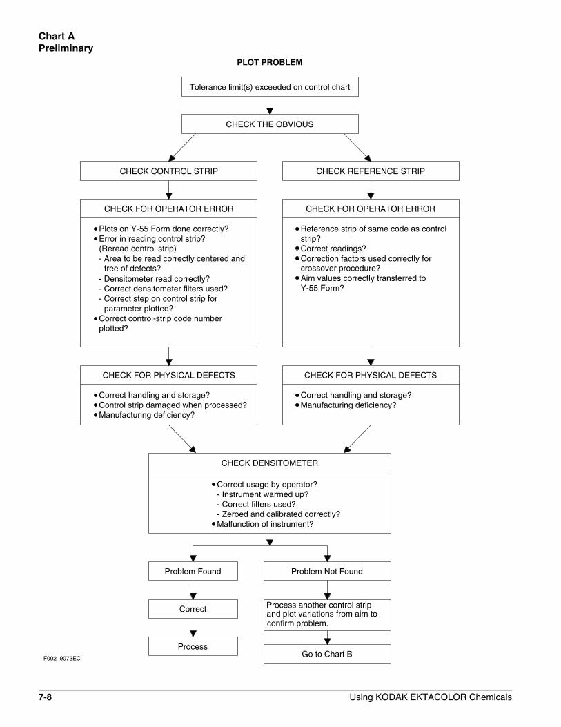
7-8 Using KODAK EKTACOLOR Chemicals
Chart A Preliminary
PLOT PROBLEM
Tolerance limit(s) exceeded on control chart
CHECK DENSITOMETER
CHECK CONTROL STRIP CHECK REFERENCE STRIP
CHECK FOR OPERATOR ERROR CHECK FOR OPERATOR ERROR
Plots on Y-55 Form done correctly?Error in reading control strip?(Reread control strip)- Area to be read correctly centered and
free of defects?- Densitometer read correctly?- Correct densitometer filters used?- Correct step on control strip for
parameter plotted?Correct control-strip code numberplotted?
Correction factors used correctly forCorrect readings?strip?Reference strip of same code as control
crossover procedure?Aim values correctly transferred toY-55 Form?
Manufacturing deficiency?Control strip damaged when processed?Correct handling and storage?
CHECK FOR PHYSICAL DEFECTS CHECK FOR PHYSICAL DEFECTS
Manufacturing deficiency?Correct handling and storage?
Correct usage by operator?- Instrument warmed up?- Correct filters used?
Malfunction of instrument?- Zeroed and calibrated correctly?
Problem Found Problem Not Found
Correct
ProcessGo to Chart B
CHECK THE OBVIOUS
Process another control stripand plot variations from aim to confirm problem.
F002_9073EC

Using KODAK EKTACOLOR Chemicals 7-9
Chart BSummary—Control-Chart Plots
below action limits
Low BP, HD LD, or LD plotswith one or more plots
brown appearance
See Chart G
Yellow patch has muddy
Paper
the most severe problem.corresponds to the density plot that hasparameter, look first at the one thatlimits are exceeded in more than oneplot that is out of control. If tolerenceboxes that matches the density
FURTHER IDENTIFY ANDGO TO SPECIFIED CHART
DESCRIBEPLOT PATTERN
Visual Appearance of
See Charts G, H, and I
High BP, HD LD, or LD plotswith one or more plots above
See Chart C
action limits
See Chart D
D-minHigh Plots
See Chart E
and Bleach-FixVisual Appearance of Developer
See Chart F
F002_9074EC
Find the description in one of the

7-10 Using KODAK EKTACOLOR Chemicals
Chart CControl-Chart Plots—High BP, HD – LD or LD
F002_9088EC
time,
tem
pera
ture
.C
orre
ct b
leac
h-fix
rep
leni
shm
ent r
ate,
Rep
lace
wor
n de
velo
per
sque
egee
s.
Reb
leac
hing
test
Infr
ared
sco
peV
erify
with
:B
leac
h-F
ixbl
each
-fix
high
pH
or
dilu
tion
ofR
etai
ned
silv
er d
ue to
See
Cha
rt 1
b. D
ump
part
ially
.a.
Wai
t and
tole
rate
.
Dep
endi
ng o
n se
verit
yof
pro
blem
:
c. D
ump
com
plet
ely.
PR
OB
LE
MP
LO
T
Che
ck p
robl
emar
eas
regu
larly
.
Dev
elop
er
PR
OC
ES
SIN
GS
OL
UT
ION
PR
EV
EN
TR
EC
UR
RE
NC
EE
LIM
INA
TE
SY
MP
TO
ME
LIM
INA
TE
CA
US
EV
ER
IFY
CA
US
EP
RO
BA
BL
E C
AU
SE
CH
OO
SE
Hig
h B
P, H
D
LD, o
r LD
plot
s w
ith o
ne o
r m
ore
plot
s ab
ove
actio
n lim
its
Adj
ust d
evel
oper
tim
e to
spe
cific
atio
ns.
Che
ck d
evel
oper
tim
e
Dev
elop
er o
verc
once
n-tr
ated
due
to e
vapo
ratio
nS
ee C
hart
1
with
ble
ach-
fixD
evel
oper
con
tam
inat
ed
See
Cha
rt 2
too
muc
h re
plen
ishe
rD
evel
oper
sta
rt-u
p ta
nk
See
Cha
rt 1
See
Cha
rt 1
Dev
elop
er s
tart
-up
tank
mix
ing
erro
rsD
evel
oper
rep
leni
sher
See
Cha
rt 1
too
conc
entr
ated
Dev
elop
er r
eple
nish
er
See
Cha
rt 1
repl
enis
hmen
t rat
eH
igh
deve
lope
r
See
Cha
rt 1
tem
pera
ture
Hig
h de
velo
per
See
Cha
rt 1
Long
dev
elop
er ti
me
Mai
ntai
n ro
utin
e m
onito
ring
sche
dule
.
spec
ifica
tions
. M
aint
ain
Adj
ust d
evel
oper
tem
pera
ture
toC
heck
dev
elop
erte
mpe
ratu
rero
utin
e m
onito
ring
proc
edur
es.
rout
ine
mon
itorin
g pr
oced
ures
.
Adj
ust d
evel
oper
rep
leni
shm
ent r
ate
repl
enis
hmen
t rat
eC
heck
dev
elop
erto
spe
cific
atio
ns.
Mai
ntai
n
Cor
rect
mix
ing
proc
edur
es.
proc
edur
es a
nd c
alib
ratio
nC
heck
mix
ing
Cal
ibra
te m
ix ta
nk.
of m
ix ta
nk
Look
for
blea
ch-f
ix le
aks
orB
e su
re m
ixin
g eq
uipm
ent i
s cl
ean.
Che
ck fo
r bl
each
-fix
cont
amin
atio
n of
deve
lope
r ta
nk o
rre
plen
ishe
r so
lutio
nssp
lash
-bac
k in
to d
evel
oper
.
Che
ck to
ppin
g pr
oced
ure
Add
wat
er to
com
pens
ate
for
deve
lope
r ev
apor
atio
n lo
sses
.
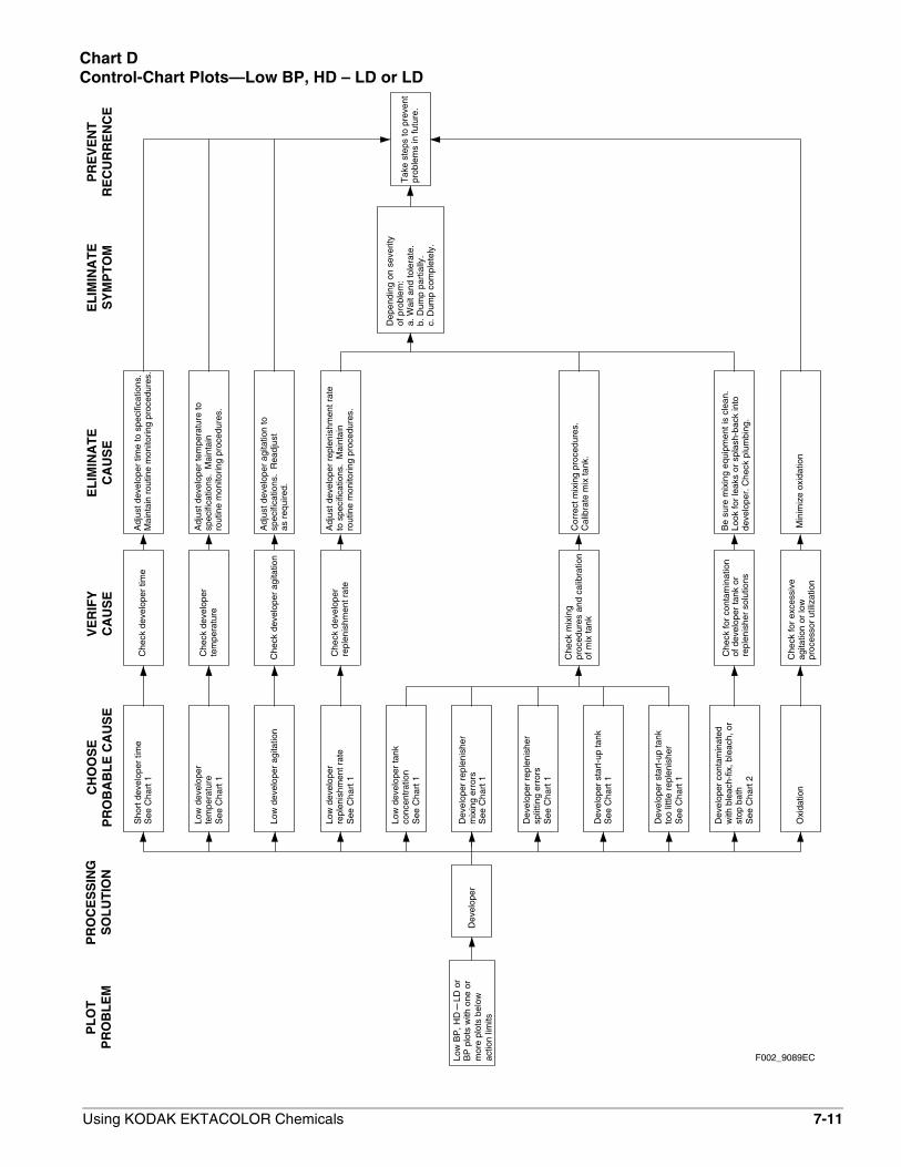
Using KODAK EKTACOLOR Chemicals 7-11
Chart DControl-Chart Plots—Low BP, HD – LD or LD
F002_9089ECactio
n lim
itsS
ee C
hart
1
conc
entr
atio
nLo
w d
evel
oper
tank
See
Cha
rt 1
rout
ine
mon
itorin
g pr
oced
ures
.
Adj
ust d
evel
oper
rep
leni
shm
ent r
ate
to s
peci
ficat
ions
. M
aint
ain
See
Cha
rt 1
repl
enis
hmen
t rat
eLo
w d
evel
oper
repl
enis
hmen
t rat
eC
heck
dev
elop
er
b. D
ump
part
ially
.a.
Wai
t and
tole
rate
.
Dep
endi
ng o
n se
verit
yof
pro
blem
:
c. D
ump
com
plet
ely.
PR
OB
LE
MP
LO
T
Tak
e st
eps
to p
reve
ntpr
oble
ms
in fu
ture
.
Dev
elop
er
PR
OC
ES
SIN
GS
OL
UT
ION
PR
EV
EN
TR
EC
UR
RE
NC
EE
LIM
INA
TE
SY
MP
TO
ME
LIM
INA
TE
CA
US
EV
ER
IFY
CA
US
EP
RO
BA
BL
E C
AU
SE
CH
OO
SE
Low
BP
, HD
L
D o
rB
P p
lots
with
one
or
mor
e pl
ots
belo
w
Adj
ust d
evel
oper
tim
e to
spe
cific
atio
ns.
Che
ck d
evel
oper
tim
e
Oxi
datio
n
with
ble
ach-
fix, b
leac
h, o
rD
evel
oper
con
tam
inat
ed
See
Cha
rt 2
too
little
rep
leni
sher
Dev
elop
er s
tart
-up
tank
See
Cha
rt 1
See
Cha
rt 1
Dev
elop
er s
tart
-up
tank
split
ting
erro
rsD
evel
oper
rep
leni
sher
See
Cha
rt 1
mix
ing
erro
rsD
evel
oper
rep
leni
sher
Low
dev
elop
er a
gita
tion
See
Cha
rt 1
tem
pera
ture
Low
dev
elop
er
See
Cha
rt 1
Sho
rt d
evel
oper
tim
eM
aint
ain
rout
ine
mon
itorin
g pr
oced
ures
.
spec
ifica
tions
. M
aint
ain
Adj
ust d
evel
oper
tem
pera
ture
toC
heck
dev
elop
erte
mpe
ratu
rero
utin
e m
onito
ring
proc
edur
es.
as r
equi
red.
Adj
ust d
evel
oper
agi
tatio
n to
Che
ck d
evel
oper
agi
tatio
nsp
ecifi
catio
ns.
Rea
djus
t
Cor
rect
mix
ing
proc
edur
es.
proc
edur
es a
nd c
alib
ratio
nC
heck
mix
ing
Cal
ibra
te m
ix ta
nk.
of m
ix ta
nk
Look
for
leak
s or
spl
ash-
back
into
Be
sure
mix
ing
equi
pmen
t is
clea
n.C
heck
for
cont
amin
atio
nof
dev
elop
er ta
nk o
rre
plen
ishe
r so
lutio
nsde
velo
per.
Che
ck p
lum
bing
.
Min
imiz
e ox
idat
ion
Che
ck fo
r ex
cess
ive
agita
tion
or lo
wpr
oces
sor
utili
zatio
n
stop
bat
h

7-12 Using KODAK EKTACOLOR Chemicals
Chart EControl-Chart Plots—High D-min
Cle
an s
tabi
lizer
rac
ks/r
olle
rsE
xam
ine
stab
ilize
r ra
cks,
rolle
rsD
epos
its fr
om d
irty
stab
ilize
r ra
cks,
rol
lers
Exa
min
e w
ash
rack
s,D
epos
its fr
om d
irty
was
hC
lean
was
h ra
cks/
rolle
rsro
llers
rack
s, r
olle
rs
Low
-leve
l whi
le
Saf
elig
ht fo
gpa
per.
wat
tage
bul
b, c
orre
ct d
ista
nce
from
Rep
lace
fade
d fil
ter.
Use
cor
rect
Pro
cess
str
ip w
ith n
osa
felig
ht
(in m
inila
b)S
tabi
lizer
Was
h
Dum
p de
velo
per
Dum
p bl
each
-fix
Dum
p bl
each
-fix
Dum
p st
abili
zer
Rep
lace
dam
aged
or
wor
nC
heck
dev
elop
ersq
ueeg
ees.
Reb
leac
han
d re
fix.
Ble
ach-
fix ta
nk e
xces
sive
lydi
lute
d w
ith d
evel
oper
sque
egee
s. R
ealig
n sq
ueeg
ees.
rout
ine
mon
itorin
g pr
oced
ures
.sp
ecifi
catio
ns.
Mai
ntai
nA
djus
t was
h-w
ater
rat
e to
Che
ck w
ash-
wat
er r
ate
Insu
ffici
ent w
ashi
ng
blea
ch-f
ixbl
each
-fix
aer
atio
n.C
heck
tank
turn
over
rat
e.
Che
ck fo
r so
urce
of
Avo
id e
xces
sive
oxi
datio
n of
Dev
elop
er
Dar
kroo
m
Elim
inat
e ca
use
of o
xida
tion
Che
ck p
roce
ssor
util
izat
ion;
chec
k fo
r so
urce
of a
erat
ion
Dev
elop
er o
xida
tion
light
leak
s
rate
.re
plen
ishm
ent r
ate
turn
over
rat
e an
dC
heck
sta
biliz
er ta
nkIn
crea
se m
achi
ne u
tiliz
atio
n.In
crea
se s
tabi
lizer
rep
leni
shm
ent
blea
ch-f
ix c
onta
min
atio
nC
heck
for
sour
ce o
f E
limin
ate
caus
e
Elim
inat
e lig
ht le
aks
in d
arkr
oom
slig
ht fo
g
Dev
elop
er c
onta
min
ated
with
ble
ach-
fixS
ee C
hart
2
Sul
furiz
atio
n of
blea
ch-f
ix
or b
iolo
gica
l gro
wth
Sul
furiz
atio
n of
blea
ch-f
ix c
arry
over
Che
ck d
arkr
oom
s fo
r
plot
s hi
ghD
-min
CH
OO
SE
PR
OB
AB
LE
CA
US
EC
AU
SE
VE
RIF
YC
AU
SE
EL
IMIN
AT
ES
YM
PT
OM
EL
IMIN
AT
ER
EC
UR
RE
NC
EP
RE
VE
NT
OF
PR
OB
LE
ML
OC
AT
ION
Ble
ach-
Fix
prob
lem
in fu
ture
Tak
e st
eps
to p
reve
nt
PL
OT
PR
OB
LE
M
c. D
ump
com
plet
ely.
of p
robl
em:
Dep
endi
ng o
n se
verit
y
a. W
ait a
nd to
lera
te.
b. D
ump
part
ially
.
Go
to C
hart
CH
igh
deve
lope
r ac
tivity
F002_9090EC

Using KODAK EKTACOLOR Chemicals 7-13
Chart FControl-Chart Plots—Visual Appearance – Developer and Bleach-Fix
or p
roce
ssor
tank
s
Yel
low
or
yello
wis
h-w
hite
prec
ipita
te in
rep
leni
sher
SO
LU
TIO
NP
RO
CE
SS
ING
Ble
ach-
Fix
VIS
UA
LP
RO
BL
EM
PR
EV
EN
TR
EC
UR
RE
NC
EE
LIM
INA
TE
SY
MP
TO
ME
LIM
INA
TE
CA
US
EV
ER
IFY
CA
US
EP
RO
BA
BL
E C
AU
SE
CH
OO
SE
Dev
elop
erde
velo
per
repl
enis
her
Exc
essi
ve m
ixin
g of
Tar
tank
sol
utio
npr
ecip
itate
in s
easo
ned
Gra
yish
-whi
te to
bla
ck
Hig
h te
mpe
ratu
re
Air
leak
s in
Low
tank
turn
over
rat
eS
ulfu
rizat
ion
from
reci
rcul
atio
n sy
stem
Hig
h te
mpe
ratu
re
Air
leak
s in
Low
tank
turn
over
rat
eS
ulfu
rizat
ion
from
reci
rcul
atio
n sy
stem
Che
ck m
ixin
g pr
oced
ure
Cor
rect
mix
ing
proc
edur
e
c. D
ump
com
plet
ely.
b. D
ump
part
ially
.a.
Wai
t and
tole
rate
.se
verit
y of
pro
blem
:D
epen
ding
on
Che
ck p
robl
emar
eas
regu
larly
Che
ck m
ix fr
eque
ntly
.C
heck
tem
pera
ture
.
Che
ck p
roce
ssor
utili
zatio
n. C
heck
for
air
leak
s in
rec
ircul
atio
n sy
stem
. Che
ck te
mp-
erat
ure.
(If
prec
ipita
teap
pear
s on
prin
ts,
you
can
wip
e it
off
easi
ly w
ith c
otto
nm
oist
ened
with
wat
er.)
Add
mor
e pr
eser
vativ
e.re
circ
ulat
ion
syst
em.
Rep
air
and
mai
ntai
npr
oces
sing
vol
ume.
appr
opia
te to
you
rfo
rmul
atio
n of
ble
ach-
fixex
cess
ive
heat
. C
hoos
eox
idat
ion
or s
ourc
e of
Elim
inat
e ex
cess
ive
Dum
p bl
each
-fix
Milk
y ap
pear
ance
(cry
stal
lizat
ion)
in r
eple
nish
er
befo
re a
ddin
gM
ix e
rror
, too
littl
e w
ater
agita
tion
betw
een
conc
entr
ates
, poo
rC
heck
mix
ing
proc
edur
eC
orre
ct m
ixin
g pr
oced
ure
conc
entr
ate
addi
tions
repl
enis
her
Dum
p de
velo
per

7-14 Using KODAK EKTACOLOR Chemicals
Chart GControl-Chart Plots—Visual Appearance of Paper
solu
tion
stor
age
cond
ition
s.
oxid
atio
n. C
heck
as r
ecom
men
ded
Fog
Pur
ple
fog
Dep
endi
ng o
n
Dum
p so
lutio
n
Che
ck fo
r lig
ht le
aks
inda
rkro
om a
nd p
rintin
gar
eas
Whi
te li
ght l
eak
safe
light
was
use
dC
heck
to s
ee if
Exp
osur
e to
saf
elig
ht
Ligh
t fog
CH
OO
SE
PR
OB
AB
LE
CA
US
EC
AU
SE
VE
RIF
YC
AU
SE
EL
IMIN
AT
ES
YM
PT
OM
EL
IMIN
AT
ER
EC
UR
RE
NC
EP
RE
VE
NT
area
s re
gula
rlyC
heck
pro
blem
PR
OD
UC
TP
RO
BL
EM
Yel
low
or
brow
nish
appe
aran
ce
Tea
r in
ligh
ttigh
t inn
erw
rapp
er o
f rol
l pap
er
Che
ck h
andl
ing
pro-
cedu
res.
Che
ck w
rapp
ers
of u
nexp
osed
rol
ls.
Do
not u
se s
afel
ight
Han
dle
pape
r ca
refu
lly
dark
room
or
prin
ting
area
sE
limin
ate
light
leak
s in
F002_9079EC
evid
ence
of b
iolo
gica
lC
heck
was
h ta
nks
for
tar
cann
ot b
e ea
sily
evid
ence
of t
ar.
On
prin
t,re
plen
ishe
r ta
nk fo
r
Dev
elop
er ta
r
Bio
logi
cal g
row
th in
Cor
rect
mix
ing
proc
edur
e
repl
enis
hmen
t rat
e an
d
Elim
inat
e so
urce
of
Cle
an ta
nks
and
rolle
rsw
ash
tank
Sul
furiz
atio
n in
seas
oned
ble
ach-
fix ta
nk
grow
th
Che
ck d
evel
oper
rem
oved
with
cot
ton
moi
sten
ed w
ith w
ater
.
Che
ck b
leac
h-fix
tank
for
blac
k pr
ecip
itate
. O
n pr
int,
depo
sit l
ooks
like
dev
elop
erta
r, b
ut c
an b
e re
mov
edfr
om e
mul
sion
by
wip
ing
prin
t with
cot
ton
moi
sten
edw
ith w
ater
.
Bla
ck d
epos
its o
n pr
ints
Che
ck h
andl
ing
Impr
oper
han
dlin
g of
unex
pose
d pa
per
proc
edur
esF
inge
rprin
ts
(or
was
h w
ater
)
seve
rity
of p
robl
em:
a. W
ait a
nd to
lera
te.
b. D
ump
part
ially
.c.
Dum
p co
mpl
etel
y.
Ver
ify w
ithin
frar
ed s
cope
orR
eble
achi
ng te
st
Ret
aine
d si
lver
in p
rint
due
to a
bnor
mal
cond
ition
of b
leac
h-fix
Cor
rect
han
dlin
gpr
oced
ures
(red
dish
mar
ks)
mud
dy b
row
n ap
pear
ance
Yel
low
pat
ch h
asR
epla
ce w
orn
deve
lope
rsq
ueeg
ees.
Cor
rect
blea
ch-f
ix r
eple
nish
men
tra
te, t
ime,
tem
pera
ture
.

Using KODAK EKTACOLOR Chemicals 7-15
Chart HControl-Chart Plots—Visual Appearance of Paper
Adj
ust s
quee
gees
.C
lean
or
repl
ace
rolle
rs.
Cor
rect
dry
ing
cond
ition
s.
proc
edur
esC
orre
ct h
andl
ing
sque
egee
sor
poo
rly a
ligne
d
cond
ition
s
spla
shin
g
proc
edur
es
proc
edur
es
pick
-off
stre
aks
from
spl
ashi
ng
spot
s lo
ok li
ke c
omet
tails
)
Whi
te, y
ello
w, o
r re
d
or u
neve
n dr
ying
.sq
ueeg
eed
befo
re d
ryin
gpr
oces
sing
. Prin
ts n
otS
plas
hing
of w
ater
afte
r
durin
g pr
oces
sing
Spl
ashi
ng o
f ble
ach-
fix
befo
re p
roce
ssin
gS
plas
hing
of b
leac
h-fix
proc
essi
ngC
orre
ct h
andl
ing
proc
edur
es
Cor
rect
mix
ing
proc
edur
e
spla
sh s
pots
(so
met
imes
prin
ting
area
Che
mic
al d
ust i
n or
nea
r
Spl
ashi
ng o
f wat
er p
rior
toLi
ght-
dens
ity s
pots
Cya
n or
blu
e sp
ots
Che
ck m
ixin
g pr
oced
ure
Che
ck h
andl
ing
Che
ck h
andl
ing
Scr
atch
es o
r em
ulsi
on
Dul
l spo
ts o
r st
reak
s
Mag
enta
-red
spo
ts a
nd
F002_9080EC
Elim
inat
e sp
lash
ing
Elim
inat
e sp
lash
ing.
proc
edur
es. C
heck
dry
ing
Che
ck h
andl
ing
PR
OB
LE
MP
RO
DU
CT
Che
ck p
robl
emar
eas
regu
larly
PR
EV
EN
TR
EC
UR
RE
NC
EE
LIM
INA
TE
CA
US
EV
ER
IFY
CA
US
EP
RO
BA
BL
E C
AU
SE
CH
OO
SE
Phy
sica
l abr
asio
n
Che
ck p
roce
ssor
rol
lers
for
dirt
y or
stu
ck r
olle
rs
Che
ck p
roce
ssor
for

7-16 Using KODAK EKTACOLOR Chemicals
blea
ch-f
ix ta
nk (
stre
akin
gIn
adeq
uate
agi
tatio
n in
firs
t
cold
une
xpos
ed p
aper
sque
egee
s
pack
age
sque
egee
s
F002_9081EC
befo
re r
emov
ing
it fr
omA
llow
pap
er to
war
m u
p
for
sour
ces
of s
crat
ches
proc
edur
e
blea
ch-f
ix ta
nk
Non
unifo
rm a
reas
Low
hum
idity
in la
b ar
ea
deve
lopm
ent
Abr
asio
n du
ring
emul
sion
sur
face
due
toM
oist
ure
colle
ctin
g on
stop
ping
of d
evel
opm
ent)
Adj
ust a
gita
tion
Adj
ust o
r re
plac
e
or m
ottle
carr
yove
rE
xces
sive
dev
elop
er
resu
lts fr
om n
on-u
nifo
rm
Che
ck d
evel
oper
exi
t
Che
ck h
andl
ing
Che
ck a
gita
tion
of fi
rst
Sta
tic m
arks
Fin
e pl
us d
ensi
ty li
nes
Adj
ust p
aper
pro
cess
or
Use
a h
umid
ifier
Che
ck h
umid
ity
PR
OB
LE
MP
RO
DU
CT
Che
ck p
robl
emar
eas
regu
larly
PR
EV
EN
TR
EC
UR
RE
NC
EE
LIM
INA
TE
CA
US
EV
ER
IFY
CA
US
EP
RO
BA
BL
E C
AU
SE
CH
OO
SE
Che
ck p
aper
pro
cess
or
Mag
enta
str
eaki
ngor
mot
tle
Chart IControl-Chart Plots—Visual Appearance of Paper

Using KODAK EKTACOLOR Chemicals 7-17
CONTROL-CHART EXAMPLESGenerally, the control-plot patterns you can detect when you use KODAK PROFESSIONAL Pro Strips, Process RA-4, result from processing problems that can be summarized in the following three charts. The charts are intended only as guides; your plots may not look exactly like these examples.
The exact appearance of the control plot depends on the specific mechanical design of the processor and the condition of the chemical concentrations in the processor tank. You may also have more than one problem affecting your process. Beside each chart is a description of potential causes and remedies for problems.
Use these charts with the DIAGNOSTIC CHARTS and the descriptions under INTERPRETING YOUR CONTROL PLOT to analyze process problems.
Although we have not included a control plot pattern for the effects of developer oxidation, a discussion of the results you can expect and the possible remedies follows the control chart examples.
Chart Solution Condition
1 Developer Developer Activity
2 Developer Contamination with Bleach-Fix
3 Bleach-Fix Leuco-Cyan Dye

7-18 Using KODAK EKTACOLOR Chemicals
Developer Activity
Developer—High or Low ActivityWhen the developer activity is too high relative to the process aim, the density of the processed materials will be too high, and the materials will be dark. If the developer activity is too low, the materials will be too light.
High and low developer activity have several potential causes. They all produce control-plot patterns very similar to that shown in Chart 1. The process problems that would cause the large shifts shown in Chart 1 would result from gross errors in operation. For example, a low-temperature shift of –11°F or a high-temperature shift of +11°F would cause shifts of the magnitude plotted here.
If your problem is caused by high or low developer activity, you should consider each of the potential causes. Also, be aware that the condition may have more than one cause, or one problem may be partially compensating for another. When you detect a developer-activity problem, it is good practice to verify all the operational conditions for the processor.
Chart 1
F002_9086EC
+
D-min
.15
.10
0
.05
.05+
.15
.05
.05
0
.10
LD+
0
.20
.25
.15
.10
.05
+
.05
.15
.10
.20
.25
.20
.25
.10
.15
.05
0BP
.15
.05
.10
.20
.25
HD LD

Using KODAK EKTACOLOR Chemicals 7-19
Developer—Time Too Short or Too LongThe recommended developer time for Processes RA-4 is 45 seconds. If the developer time is too short or too long, it will affect development and the amount of dye formed.
Developer times that are too long will produce higher-than-normal LD, HD – LD, and BP density values. Developer times that are too short will produce lower-than-normal LD, HD – LD, and BP density values.
Developer-time variations can occur in processors because of variations in electrical load and differences in motor temperature from a cold start to equilibrium. Electrical-load variations can be caused by other equipment (e.g., a heater) on the same power line. In some cases, you may need a voltage regulator on the processor drive motor to compensate for external voltage variations.
Mechanical problems, such as misaligned moving parts, can cause developer-time problems. Be sure that the transport is functioning properly. Extended developer times can also result from intermittent paper slippage in the developer tank. Use a stopwatch to measure the developer time, and compare it with the machine setting.
Developer—Temperature Too Low or Too HighThe recommended developer temperature for Process RA-4 is 35 ±0.3°C (95.0 ± 0.5°F) for KODAK EKTACOLOR RA Developer Replenisher or KODAK EKTACOLOR RA Developer Replenisher RT. For EKTACOLOR Developer Replenisher 12 (EKTACOLOR Developer Replenisher 161 in Europe) and EKTACOLOR PRIME Developer Replenishers, the recommended temperature is 37.8 ± 0.3°C (100.0 ± 0.5°F).
A developer temperature that is too low or too high affects development and the amount of dye formed. If the developer temperature is too high, the density values for LD, HD – LD, BP, and perhaps D-min will plot higher than normal. If the developer temperature is too low, the density values for LD, HD – LD, and BP will plot lower than normal.
If you suspect that the developer temperature is incorrect:• Check that the temperature regulator is operating.
• Check that the developer had enough time to reach operating temperature before processing.
• Check that the temperature of the replenisher solution was not too low or too high.
• If your processor has more than one developer tank, check that the temperature is the same in all tanks. Check that the temperature within each tank is uniform from top to bottom and side to side.
• Check that the developer recirculation filter is not clogged. A clogged filter can prevent proper heating of the solution. Check for constricted circulation lines.
The temperature controller and the recirculation system—individually or in combination—can cause temperature problems. Replace the recirculation filters if they are clogged.
If the temperature of the developer replenisher is too low or too high, it may be affecting the temperature of the tank solution. If this occurs, you may need to provide more heat in the replenisher storage area or heat the replenisher before using it.
Check the developer temperature frequently, and adjust it as necessary. Also, check the developer temperature periodically while the processor is operating under full load. The heater may not be able to maintain the temperature as fresh replenisher and a maximum load of paper are entering the developer.

7-20 Using KODAK EKTACOLOR Chemicals
Developer—Replenishment Rate Too Low or Too HighDeveloper activity varies directly with the replenishment rate. If the rate is too low, the LD, BP, and HD – LD density values will plot lower than normal. If the rate is too high, the density values for LD and BP will plot higher than normal. The amount of change that you see in control-strip plots due to incorrect replenishment depends on the developer-tank volume, processor speed, and the amount of paper processed.
The recommended replenishment rates are starting points only. The exact rate depends on the type of processor and replenisher mixing and storage conditions. It can also depend on how well you maintain operating conditions, such as development time and temperature. Determine your exact rate by monitoring the process with control strips and adjusting the rate as needed according to the control plots. Do not adjust the rate to “chase” small changes in the control plots. Once the process is in control, continue to use the rate you established; don’t change it unless processor utilization changes. Be aware that the rate of change after a replenishment-rate adjustment may be relatively slow; you may not see the full impact of a developer replenishment-rate change for several weeks.
To avoid replenishment problems, check the replenisher settings regularly to be sure that the correct rates and tank volumes are maintained.
If you suspect that replenishment is the problem:• Check that the replenishment system is set correctly.
• Check that your calculations are correct if you set your replenishment rate for the average paper width being processed. Does the paper width vary seasonally? Check your replenishment rate by using this calculation.
• Check that the processor was receiving replenishment when you detected the problem.
• Check for a possible mechanical problem with the replenishment system. Is the system replenishing at a constant and repeatable rate?
Flow Processor Paper Replenishment
Rate = Speed x Width x Rate
(mL/min) (m/min or ft/min) (m or ft) (mL/m2 or ft2)
If underreplenishment is the cause of the problem, adjust the replenishment rate to the correct rate. To correct the underreplenished processor tank condition, remove enough developer tank solution so that you can add replenisher in 5- to 10-percent increments of tank volume. Repeat if needed to correct the tank condition. After each addition, recirculate the developer for approximately 10 minutes before you process another control strip.
If overreplenishment is the cause of the problem, adjust the replenishment rate to the correct rate. To correct the overreplenished processor tank condition, remove enough developer tank solution so that you can add water and starter to bring the process back into control. Add one part starter to 11 parts water. If the process is not far out of control, add the water and starter in 5-percent increments of tank volume. If the process is grossly out of control, add water and starter in 10-percent increments. After each addition, recirculate the developer for approximately 10 minutes before you process another control strip. If the process is still out of control after you have added water and starter equivalent to 20 percent of the tank volume, replace the tank solution with a fresh mix.

Using KODAK EKTACOLOR Chemicals 7-21
Developer—Fresh-Tank Mixing Error—Too Little or Much StarterUsing too little starter in a fresh developer mix will increase developer activity. You will see this in the control plots as an increase in the LD and HD – LD density values.
Using too much starter for a fresh developer tank solution decreases developer activity. You will see this in the control plots as a decrease in the LD, HD – LD, and BP density values.
To avoid these fresh-tank mixing errors, carefully follow the directions provided with the developer.
If you know the amount of starter that was left out, you can add the missing amount. If you added too much starter or do not know the amount of the error, it will be difficult to correct the problem without a chemical analysis. Replace the tank solution with a fresh mix.
Developer—Mixing Error—Incorrect Water/Replenisher RatioDeveloper activity is affected by a mix that is prepared with too little replenisher and topped with water, or with too little water and topped with replenisher.
Using too much water and too little replenisher has the greater effect. You will see this as lower-than-normal LD, HD – LD, and BP values in the control plots.
If you use too much replenisher and too little water, the effect in the control charts will be slight.
Review your mixing procedures and verify the mix-tank calibration. Follow the mixing order in the instructions provided with the chemicals.
Because it is very difficult to determine the exact cause or amount of this type of mixing error without chemical analysis, replace the solution with a fresh mix.
Developer—Replenisher Mixing Error—Too Little or Too Much Part AUsing the wrong amount of any of the developer components affects developer activity. Too little Part A causes high activity; too much Part A causes low activity.
Omitting Part A entirely usually results from human error. However, the chance of leaving out just a portion increases if you split the packaged developer to mix a smaller volume. Errors of 5 to 10 percent will affect the control plots. Be sure that your measuring device is accurate and that you use it correctly. Check that you have calculated the amounts correctly, and that you added the correct amount.
To reduce errors, always use accurate measuring equipment. Graduated cylinders calibrated in millilitres, not ounces, are the most accurate. If you use an automatic mixer, be sure it is properly calibrated for the volumes being mixed. Review mixing procedures for possible sources of error.
Because it is very difficult to determine the exact cause or amount of this type of mixing error without chemical analysis, replace the solution with a fresh mix.
Developer Replenisher Mixing Error—Too Little or Too Much Part BUsing the wrong amount of any of the developer components affects developer activity.
Omitting Part B entirely usually results from human error. However, the chance of leaving out just a portion increases if you split the packaged developer to mix a smaller volume. Errors of 5 to 10 percent will affect the control plots. Be sure that your measuring device is accurate and that you use it correctly. Check that you have calculated the amounts correctly, and that you added the correct amount.
To reduce errors, always use accurate measuring equipment. Graduated cylinders calibrated in millilitres, not ounces, are the most accurate. If you use an automatic mixer, be sure it is properly calibrated for the volumes being mixed. Review mixing procedures for sources of possible error.
Because it is very difficult to determine the exact cause or amount of this type of mixing error without chemical analysis, replace the solution with a fresh mix.
Developer—Replenisher Mixing Error—Too Little or Too Much Part CUsing the wrong amount of any of the developer components affects developer activity. Too little Part C causes low activity; too much Part C causes high activity.
Omitting Part C entirely usually results from human error. However, the chance of leaving out just a portion increases if you split the packaged developer to mix a smaller volume. Errors of 5 to 10 percent will affect the control plots. Be sure that your measuring device is accurate and that you use it correctly. Check that you have calculated the amounts correctly, and that you added the correct amount.
To reduce errors, always use accurate measuring equipment. Graduated cylinders calibrated in millilitres, not ounces, are the most accurate. If you use an automatic mixer, be sure it is properly calibrated for the volumes being mixed. Review mixing procedures for sources of possible error.
Because it is very difficult to determine the exact cause or amount of this type of mixing error without chemical analysis, replace the solution with a fresh mix.

7-22 Using KODAK EKTACOLOR Chemicals
Developer—Contamination With Bleach-FixChart 2 demonstrates that very small amounts of thiosulfate (also called hypo) from the bleach-fix will contaminate the developer. As little as 0.1 mL of bleach-fix per litre of developer can put a process out of control. If the developer is contaminated with bleach-fix, you will see a severe color change in the prints and large shifts in the control plots. You will also see an increase in D-min.
The chart shows the typical plot pattern that results from bleach-fix contamination of a developer tank. The degree of contamination is severe in this example; the most severe contamination shown is at 2.4 mL of EKTACOLOR RA Bleach-Fix NR Replenisher per litre of developer.
Possible causes of bleach-fix contamination are bleach-fix splashed into the developer when the racks are raised or mixing developer with equipment that contains a small amount of bleach-fix. Check for any procedures that might cause splashing during mixing or processing. If possible, use separate mixing tanks for developers, and wash all mixing equipment thoroughly before reusing it.
Stop production until you find the source of the contamination. A developer contaminated with bleach-fix or fixer cannot be salvaged; replace it with a fresh mix.
Chart 2
.05
.05
0D-min+
.10
0
.10
.05
.15
.05
LD+
.05
.10
.15
.25
.20
.15
0BP
HD LD
.25
.20
.10
.15
0
.05+
.05
.15
.10
.25
.20
.25
.20
.10
.05
.15
+
F002_1064EC

Using KODAK EKTACOLOR Chemicals 7-23
Bleach-Fix—Leuco-Cyan DyeChart 3 demonstrates controls plots that can result from a problem in the bleach-fix. Leuco-cyan dye is a colorless form of the cyan dye caused by poor bleach-fix performance. Prints with leuco-cyan dye will appear to have a reddish cast in the higher neutral-density regions of the images.
The most common cause of a leuco-cyan dye condition is low bleach-fix pH. This can result from overreplenishment of the bleach-fix tank or from incorrect pH adjustment if you make any manual pH adjustments. You may also observe leuco-cyan dye when you start up with a fresh mix.
If your process control plots indicate low cyan densities, verify the bleach-fix replenishment rates and avoid overreplenishment. Following the test procedure on the following page can verify the presence and significance of a leuco-cyan dye problem.
Chart 3
.05
.05
0D-min+
.10
0
.10
.05
.15
.05
LD+
.05
.10
.15
.25
.20
.15
0BP
HD LD
.25
.20
.10
.15
0
.05+
.05
.15
.10
.25
.20
.25
.20
.10
.05
.15
+
F002_1065EC

7-24 Using KODAK EKTACOLOR Chemicals
Rebleaching Test for Leuco-Cyan DyeLeuco-cyan dye is a colorless form of cyan dye. You can recover the dye by rebleaching the control strip. The degree of recovery is a measure of the amount of leuco-cyan dye. To test for leuco-cyan dye, follow these steps.
1. Zero your densitometer. Measure and record the BP density of your control strip.
2. Rebleach the control strip for 2 minutes in a known good bleach (i.e., a properly constituted Process C-41 bleach or a solution made from KODAK Farmer’s Reducer, Part A).
3. Wash the control strip for several minutes and allow it to dry.
4. Rezero your densitometer. Read the BP density of the control strip again.
5. To calculate the change in density readings, subtract the reading in step 1 from the reading in step 4. If the difference is greater than + 0.06, a leuco-cyan dye problem exists.
6. Check the pH of the bleach-fix. Use ammonium hydroxide to adjust the pH to 6.25 ±0.25. Verify replenishment rates and mixing methods.
CautionCaution AMMONIUM HYDROXIDE IS CORROSIVE. Ammonium hydroxide requires careful handling; it is strongly corrosive and can cause serious harm to the skin and eyes; it will damage clothing. For your safety, see the Material Safety Data Sheet for handling and precautionary information. Observe all CAUTION statements. Avoid contact with skin or clothing by solution or vapors. Use a ventilation hood to avoid exposure to vapors. Do not weigh this chemical in an aluminum container.
Developer—OxidationWhen developer is exposed to air, it reacts with oxygen. To protect the developing agent, developers contain preservatives that react with oxygen. However, prolonged exposure to air will eventually deplete the preservatives and cause the developing agent to oxidize. Oxidation of the developing agent causes decreased developer activity and precipitate formation.
It is difficult to produce a representative plot pattern for the effects of developer oxidation, because it depends on the degree of aeration of the tank. Also, if you adjust your developer replenishment rate in an attempt to reduce the process control bias, you may be masking the impact of the oxidation. Generally, you will see an increase in BP, HD – LD, and D-min in the control plots.
The most common causes of oxidation are excessive agitation and low processor utilization. Excessive agitation—e.g., from long or too rapid mixing or too much agitation in the processor—forces air into the solution. A faulty processor recirculation pump can also suck air into the solution. Foaming may indicate that the recirculation system is leaky and is sucking air.
Oxidation is a more common problem in roller-transport processors than in other type of processor, because the rollers constantly expose large areas of solution to the air. Oxidation is also more likely in roller-transport processors because they often have low utilization, which means that the solution is exposed to air for long periods without replenishment. Without replenishment, preservatives in the developer are not replaced as they would be with normal utilization. Evaporation is also higher in low-utilization processors, and leads to overconcentration of the developer. Overconcentration may offset some of the effects of the oxidation and mask the condition.
Minimize oxidation by turning off the processor when it is not in use. In roller-transport processors, use solutions that contain extra protection against oxidation, such as KODAK EKTACOLOR RA Developer Replenisher RT.
Check for excessive air flow over the processor developer tanks and developer replenisher storage tanks. Use floating lids on storage tanks. Avoid overmixing and excessive agitation.

![[XLS] · Web viewwms project management wms implementation service kodak imaglnk scnr 900s_ kodak imaglnk scnr 900d_ kodak imaglnk semiauto fdr kodak imaglnk patch rdr ac](https://img.pdfslide.net/doc/110x75/5ab639c47f8b9a86428d8207/xls-viewwms-project-management-wms-implementation-service-kodak-imaglnk-scnr-900s.jpg)