Embed Size (px)
Citation preview
DP Operator Course K-Pos Systems Training Manual
Jan. 2010 © Kongsberg Maritime AS Page 2.1.1 Rev. 02 Training
K-Pos Systems
Introduction The range of K-Pos DP systems provides functions which fulfil the requirements for the International Maritime Organisation (IMO) and all major classification societies, in combination with an independant joystick control system. The K-Pos DP system is type-approved by Det Norske Veritas (DNV) and American Bureau of Shipping (ABS). The Heading Control System (HCS) (Autopilot) has a mark of conformity (wheelmark) in accordance with the Marine Equipment Directive (MED) (EU Council Directive 96/98/EC on marine equipment) of the European Union.
The K-Pos Family of DP Systems The K-Pos concept consists of a number of different types of DP control systems designed for various applications and types of vessels. All the systems are based on the same hardware and software platform.
• The stand-alone systems interface with other systems, such as power plant and thrusters, via conventional signal cables and serial lines.
• The integrated systems communicate with other KONGSBERG systems such as K-Chief (MarineAutomation) andK-Thrust (Thruster Control) via a dual ethernet LAN.
The design gives the K-Pos concept a high degree of flexibility and extensive possibilities for upgrading. In addition, the K-Pos concept has a number of options in order to adapt to various demands and safety requirements. The K-Pos systems are based on a small number of flexible hardware units which form the building modules of the different system types. The same modules are also used as the building blocks for integrated systems.

K-Pos Systems DP Operator Course Training Manual
Page 2.1.2 © Kongsberg Maritime AS Jan. 2010 Training Rev. 02
The following table shows the basic systems within the K-Pos DP family. System DP-11 Stand-alone single DP control system DP-12 Integrated single DP control system DP-21 Stand-alone dual-redundant DP control system DP-22 Integrated dual-redundant DP control system DP-31 Stand-alone triple-redundant DP control system DP-32 Integrated triple-redundant DP control system The flexibility of the K-Pos concept means that systems designed for a particular class notation can be easily upgraded to fulfil the requirements of a higher class, as shown in the table below. The table shows the basic system types and the corresponding IMO Equipment Class. The remarks indicate the first stage of the upgrading possibilities. The flexibility of the K-Pos concept allows a simple upgrade path. System IMO
Equipment Class
Remarks
DP-11/12 Class 1 Can be upgraded to Equipment Class 2 DP-21/22 Class 2 Can be upgraded to Equipment Class 3 DP-31/32 Class 2 Can be upgraded to Equipment Class 3 DP-21/22 with DP-11/12
Class 3 DP-11/12 as backup
DP-31/32 with DP-11/12
Class 3 DP-11/12 as backup
The IMO Equipment Classes are defined in the IMO MSC/Circ.645 Guidelines For Vessels With Dynamic Positioning Systems.
Integrated Automation System (IAS) Integrating all the functions for monitoring and control of a vessel provides a real benefit both technically and economically. Functions can be integrated in order to reduce the overall need for hardware and software functions and to reduce interfacing requirements. This in turn leads to less demand for special software, cabling and testing. Furthermore, integrated systems offer a far greater degree of redundancy, and therefore increased system availability and operational performance.
K-Chief - Marine Automation K-Chief is a distributed vessel automation and control system covering functions such as:
• Power management • Machinery monitoring and alarm system • Auxiliary monitoring and control • Ballast monitoring and control • Cargo monitoring and control • Vessel-wide mode control

DP Operator Course K-Pos Systems Training Manual
Jan. 2010 © Kongsberg Maritime AS Page 2.1.3 Rev. 02 Training
K-Thrust - Thruster Control The thruster control system monitors and controls the vessel’s propulsion and thruster system. The system includes the following functions:
• Individual control of propulsion/thruster units • Joystick control • Station-keeping • Monitoring and control of propulsion/thruster prime power units • Monitoring and control of propulsion/thruster auxiliary units • Emergency stop of propulsion/thruster units
In an integrated system K-Thrust operator stations may also act as backup for any of the K-Pos operator stations, thereby increasing the system availability. Further information about the K-Thrust and K-Chief systems can be found in the relevant Product Descriptions.
The K-Pos OS (Operator Station) The Operator Station is available in single, dual or triple configurations. Each operator station contains a high-performance marinised computer running Windows XP. A high-resolution colour flat-screen, approved for maritime operations, provides the main graphic display for presentation of data.
K-Pos OS (single) K-Pos OS (double) K-Pos OS (triple)
The cJoy DP-OT and the cWing The cJoy DP-OT (Operator Terminal) provides a remote joystick with automatic heading and position capability for DP operation. Autopilot may be included. The cWing Terminal provides a remote joystick with automatic heading capability. It is interfaced to one K-Pos OS or cJoy DP-OT.
cJoy DP-OT cWing

K-Pos Systems DP Operator Course Training Manual
Page 2.1.4 © Kongsberg Maritime AS Jan. 2010 Training Rev. 02
The K-Pos DPC (DP Controller)
DP Controllers are available in various models providing different degrees of redundancy.
The controllers are based on the KONGSBERG System Technology with control computer modules and necessary I/O units focusing on fault tolerance through decoupling and segregation.
Internal arrangement inside the cabinet reflects the controller structure. This gives a more logical approach to controller upgrades as well as to installation and fault finding. The same cabinet can be used for single and dual systems. Triple systems use an additional top section for the third processor. This modular design provides a very easy upgrade path from single to dual and triple configurations. The number of different hardware components is kept at a minimum.
The hardware concept for a redundant solution contains: • Main processors with dedicated processor synchronisation network • Dual process LAN for communication with Operator Stations and other IAS units • I/O modules snapped on to rails with built-in dual power and RBus (high speed
serial IO-bus) • For stand-alone systems: full segregation per thruster, one I/O module per unit.
Built-in galvanic isolation and loop monitoring. • Segregation of serial line I/O. Each serial line input is read by all main processors.
Hardware concept
PWRA
PWRB
NETA
NETB
HU
B A
U31-37
U71-77U41-47
U61-67
(OPTION) (OPTION)
UPS1 UPS2
To Field
DPC-2
Legend:RBUS ARBUS BNET ANET BSERIAL
PWRA
PSU1
PSU3
NETA
NETA
NETB
NETB
HU
B B
RS
ERR
SE
RR
MP
RM
PR
MP
RM
P
HU
B AR
SER
RS
ERR
MP
RM
PR
MP
RM
P
RM
P
RM
PR
MP
RM
P
RM
PR
MP
RM
P
RM
P
RM
PR
MP
RM
P
RM
PR
MP
RM
P
Red.NetTo
Field
Section-A Section-B
501RCU
A501RCU
BPSU 3 PSU 1

DP Operator Course K-Pos Systems Training Manual
Jan. 2010 © Kongsberg Maritime AS Page 2.1.5 Rev. 02 Training
DP Hardware concept – Stand alone
Single Double Tripple
DP Hardware concept – Integrated
Single Double Tripple
Dual synchronisation network
R-Bus serial I/O bus communication with I/O modules
RMP200 I/O modules
RHUB200 R-Bus HUB
RSER200 Serial communication module
Redundant power
Dual LAN network
RCU501 processor

K-Pos Systems DP Operator Course Training Manual
Page 2.1.6 © Kongsberg Maritime AS Jan. 2010 Training Rev. 02
Controller Cabinets

DP Operator Course K-Pos Systems Training Manual
Jan. 2010 © Kongsberg Maritime AS Page 2.1.7 Rev. 02 Training

K-Pos Systems DP Operator Course Training Manual
Page 2.1.8 © Kongsberg Maritime AS Jan. 2010 Training Rev. 02
Network The network used is an industrial Local Area Network (LAN) compatible with the Ethernet IEEE 802.3 standard. The network is organised as a star-shaped structure with a switch at its centre. Designing networks with switches gives the opportunity to segment the network traffic in integrated systems. Dual- and triple-redundant stand-alone K-Pos systems, and all integrated K-Pos systems, use a dual-redundant network comprising two separate but identical networks (A and B). In integrated K-Pos systems, switches are installed in wall-mounted cabinets known as Network Distribution Units (NDU). Several interconnected NDUs may be used, depending on the scope of the system.
K-Pos DP-11 and DP-12
The DP-11 and DP-12 are single DP control systems comprising a DP controller unit (DPC-1) and a dedicated operator station (K-Pos OS). The controller unit and the operator station communicate via a dual high-speed data network for DP-12 and single network for DP-11. Both systems satisfy IMO Equipment Class 1 and corresponding class notations.
The DP-11 system provides a direct interface to the thrusters and includes the necessary interfaces to power plant, position-reference systems and sensors.
The DP-12 system is designed for integration with the KONGSBERG K-Thrust and K-Chief systems. In this configuration, the interfaces to the thruster and power systems are via a dual data network to other parts of the integrated system.
K-Pos DP-11 Standard System

DP Operator Course K-Pos Systems Training Manual
Jan. 2010 © Kongsberg Maritime AS Page 2.1.9 Rev. 02 Training
K-Pos DP-21 and DP-22
The DP-21 and DP-22 are dual-redundant DP control systems comprising a dual redundant DP controller unit (DPC-2) and two identical operator stations (K-Pos OS). The controller unit and the operator stations communicate via a dual high-speed data network. Both systems satisfy the requirements of IMO Equipment Class 2 and corresponding class notations.
The DP-21 system provides a direct interface to the thrusters and includes the necessary interfaces to power plant, position-reference systems and sensors.
The DP-22 system is designed for integration with the KONGSBERG K-Thrust and K-Chief systems. In this configuration, the interface to the propulsion and power systems is via a dual data network to the other parts of the integrated system.
Dual Redundancy
The most common redundancy concept for dynamic positioning systems is the use of redundant sensors (two or more) and a dual computer system. The dual system, often referred to as “online” and ”hot standby”, significantly increases the total availability and reliability of a system compared to a single system. The following list specifies the main advantages of redundancy:
• No single-point failure The system is designed to avoid total system failure if single failure occurs.
• Failure detection The system will detect a failure, allowing corrective actions to be taken.
• Fault isolation If one system component fails, the other components will not be affected.
• Switchover to hot standby If the online computer in a dual-redundant system fails, a successful switchover to the hot-standby computer takes place automatically.
The system provides redundancy in accordance with Class 2 requirements. The two controller computers are separate and operate independently of each other. The operator may choose which computer is to be online, while the other computer acts as the hot standby.
The two computers operate in parallel, each receiving the same input from the operator, sensors, reference systems and thrusters, and each performing the same calculations. However, only the online computer can control the thruster system. A switchover is activated either automatically, if a failure is detected in the online computer, or manually by the operator. Automatic switching is allowed only once. The operator must explicitly enable any further automatic switching.
Both control computers are continuously checked for both hardware and software failures. If a failure is detected, a warning or alarm is given.

K-Pos Systems DP Operator Course Training Manual
Page 2.1.10 © Kongsberg Maritime AS Jan. 2010 Training Rev. 02
K-Pos DP-21 Standard System
K-Pos DP-31 and DP-32
The DP-31 and DP-32 are triple-redundant DP control systems comprising a triple-redundant DP controller unit (DPC-3) and three identical operator stations. The controller unit and the operator stations communicate via a dual high-speed data network. Both systems satisfy the requirements of IMO Equipment Class 2 and corresponding class notations.
The DP-31 system provides a conventional interface to the vessel’s propulsion and power systems, while the DP-32 system is designed for integration with the KONGSBERG K-Thrust and K-Chief systems.
Triple Redundancy
Redundancy increases the availability and reliability of the K-Pos system and ensures that positioning can still be performed should a single fault occur in either the K-Pos system or the connected sensors and position-reference systems. Triple redundancy significantly increases the total availability of a system compared to a single or a dual system.
The triple redundancy incorporated in the DP-31/32 systems not only detects an error and isolates the faulty data or component, but also disregards the faulty data in the DP calculations. This means that the operator is not forced to determine which data or component is correct.

DP Operator Course K-Pos Systems Training Manual
Jan. 2010 © Kongsberg Maritime AS Page 2.1.11 Rev. 02 Training
The three DP control computers perform the same positioning tasks. Each individual computer uses the same data from each of the sensors and position-reference systems to calculate the command signals to the thrusters/propellers.
The concept of majority voting is used to detect and isolate faults in the sensors and in the K-Pos system itself. Once the voting has taken place, the failed (incorrect) computer will, if possible, correct itself automatically, based on the values of the other computers. If the failed computer cannot correct itself, the operator is informed and the faulty computer should be replaced. Meanwhile, the two other computers continue working and perform dual-redundancy procedures in the same way as a dual system. The system will automatically reconfigure itself to a triple-redundant system as soon as the failed computer is replaced.
All three control computers perform voting, but only one of the control computers (the “master” computer) communicates with the operator stations and outputs serial-line information. The operator can explicitly select the computer that is to be the master.
If the present “master” computer should fail, another computer will immediately take over the “master” responsibility.
The main advantages of triple redundancy are:
• Voting of sensor input signals The voting is performed between tightly synchronised computers to:
- Detect sensor errors such as compass drift and sensor breakdown.
- Ensure that all three computers use the same data as a basis for calculation of command signals.
• Software Implemented Fault Tolerance (SIFT)
The Triple Modular Redundancy (TMR) detects an error in the processing elements and corrects the error by employing voting algorithms. The system represents a Software Implemented Fault Tolerance (SIFT) concept.
• Voting on command (output) signals
- DP-31: The thruster commands from the three control computers are compared by the “master” computer and the median command is selected to be the final output.
- DP-32: The voting of the thruster commands is performed in the thruster control field station.
• No single-point failure
The system is designed to avoid total system failure if single failure occurs.
• Failure detection
The system will detect a failure, allowing corrective action to be taken.
• Fault isolation
If one system component fails, the other components will not be affected.
• No standby unit, all computers are “hot”
If one DP control computer fails in a triple-redundancy system, the two other computers continue working and perform dual-redundancy procedures in the same

K-Pos Systems DP Operator Course Training Manual
Page 2.1.12 © Kongsberg Maritime AS Jan. 2010 Training Rev. 02
way as a dual system. Should a second computer failure take place, there is an automatic switchover to the remaining computer.
• Hot repair
It is possible to replace a computer while the other computers continue the operation.
K-Pos DP-31 Standard System
DP Operator Course K-Pos Systems Training Manual
Jan. 2010 © Kongsberg Maritime AS Page 2.1.13 Rev. 02 Training
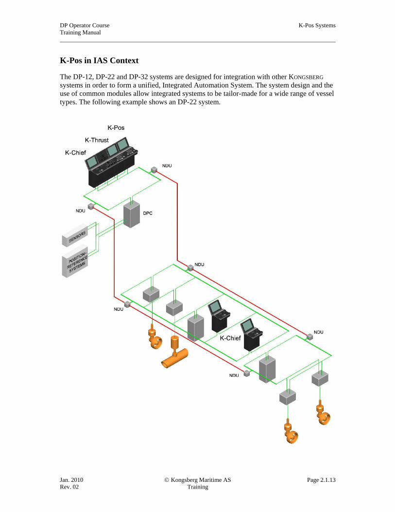
K-Pos in IAS Context
The DP-12, DP-22 and DP-32 systems are designed for integration with other KONGSBERG systems in order to form a unified, Integrated Automation System. The system design and the use of common modules allow integrated systems to be tailor-made for a wide range of vessel types. The following example shows an DP-22 system.

K-Pos Systems DP Operator Course Training Manual
Page 2.1.14 © Kongsberg Maritime AS Jan. 2010 Training Rev. 02
IMO Equipment Class 3 Systems
In order to comply with the Equipment Class 3 requirements, a DP control system with redundancy and a single DP control system must be installed separated by an A60 class division. Three sets of sensors and reference systems must be installed. One set of sensors and one reference system must be connected to the single DP control system (usually referred to as the “Fire Backup”).
K-Pos DP-21/31 and DP-11 Standard Configuration
In the following Equipment Class 3 configuration, the main DP control system could be either a DP-21 dual-redundant stand-alone DP system (as illustrated), or a DP-31 triple-redundant system. The main system has at least two sets of position-reference systems and sensors, and two uninterruptible power supply systems.
The backup is provided by a DP-11, stand-alone DP control system, equipped with its own position-reference system, sensors and uninterruptible power supply. The sensors and position-reference system of the backup is also connected to the main DP. The backup system is separated from the main DP control system by an A60 class division.
In this application, the DP-11 uses a dual high-speed data network.
A manual switchover control is located at the backup system. An additional manual change-over switch may be located at the main system.

DP Operator Course K-Pos Systems Training Manual
Jan. 2010 © Kongsberg Maritime AS Page 2.1.15 Rev. 02 Training
K-Pos DP-22/32 and DP-12 Standard Configuration
In the following Class 3 configuration of an integrated system, the main DP control system could be either a DP-22 dual-redundant system (as illustrated), or a DP-32 triple-redundant system. The main system has at least two sets of position-reference systems and sensors, and two uninterruptible power supply systems.
The backup is provided by a DP-12 single DP control system, equipped with its own position-reference system, sensors and uninterruptible power supply. The sensors and position-reference system of the backup are also connected to the main DP. The backup system is separated from the main DP control system by an A60 class division. A manual switch-over control is located at the backup system. An additional change-over switch may be located at the main system.
K-Pos Systems DP Operator Course Training Manual
Page 2.1.16 © Kongsberg Maritime AS Jan. 2010 Training Rev. 02
K-Pos Extensions and Upgrades
Operator Stations Additional DP operator stations can be connected to the data network. Each operator station operates independently. Command of the vessel can easily be transferred between the operator stations.
Operator Terminals Operator terminals (cJoy DP-OT) can be connected to the data network. Each terminal operates independently. Command of the vessel can easily be transferred between the operator stations and operator terminals.
Wing Terminals Wing terminals (cWing) can be connected to one of the operator stations/terminals. Command of the vessel can easily be transferred between the operator stations, operator terminals and wing terminals.
Controller redundancy The K-Pos DPC-1 controllers can be upgraded to DPC-2 (dual redundancy) by adding:
• a controller computer (RCU) • I/O Bus (RHUB) • preconfigured mounting plate (with fuse, power, filter, patch box for LAN,
cableducts etc.) It would also need software update and, if needed, adding units to the IO system to get proper segregation. The K-Pos DPC-2 controllers can be upgraded to DPC-3 (triple redundancy) by simply adding a third control computer (RCU).
Screen Capture Printer A screen capture printer can be connected to the data network. This gives the operator the possibility to print the current display picture.
Data Logging System Extensive data logging functions are available for the K-Pos systems as a separate History Station with recording and reviewing facilities.
IMO Equipment Class 2 The K-Pos DP-11 and DP-12 systems can be upgraded to IMO Equipment Class 2 (redundant system) by adding one or more operator stations, upgrading the DP controller to DPC-2 (or DPC-3) and add necessary reference systems and sensors.
IMO Equipment Class 3
The K-Pos DP-21/22 and DP-31/32 systems can be upgraded to the requirements of IMO Equipment Class 3 by installing an DP-11/12 system in a separate compartment and connecting it to the data network as a backup system. At least one of each sensor type and one position-reference system must be connected to the backup system.

DP Operator Course K-Pos Systems Training Manual
Jan. 2010 © Kongsberg Maritime AS Page 2.1.17 Rev. 02 Training
Integrated redundant DP control system (K-Pos DP2) with Independant Joystick system (cJoy) and levers for each thruster (K-Thrust). This setup would fulfill IMO DP class 2 requirements for DP control system if the number of sensors and position reference systems where correct.

K-Pos Systems DP Operator Course Training Manual
Page 2.1.18 © Kongsberg Maritime AS Jan. 2010 Training Rev. 02
Examle of integrated vessel control system consisting of K-Pos DP, cJoy, K-Thrust, K-Bridge and K-Chief