Embed Size (px)
Citation preview
1
Lecture #11 EGR 272 – Circuit Theory II
Read: Chapter 11 in Electric Circuits, 6th Edition by Nilsson
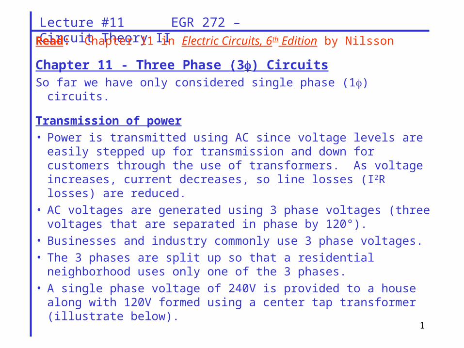
Chapter 11 - Three Phase (3) CircuitsSo far we have only considered single phase (1) circuits.
Transmission of power
• Power is transmitted using AC since voltage levels are easily stepped up for transmission and down for customers through the use of transformers. As voltage increases, current decreases, so line losses (I2R losses) are reduced.
• AC voltages are generated using 3 phase voltages (three voltages that are separated in phase by 120°).
• Businesses and industry commonly use 3 phase voltages.
• The 3 phases are split up so that a residential neighborhood uses only one of the 3 phases.
• A single phase voltage of 240V is provided to a house along with 120V formed using a center tap transformer (illustrate below).

2
Lecture #11 EGR 272 – Circuit Theory II
Advantages of 3-phase circuits:
• more efficient (smaller I2R losses)
• less vibration in machinery
• smaller conductors
Polyphase circuits
• AC voltages can be generated using various numbers of phases.
• 3 phase is the most common
• 6 and 12 phase are sometimes seen
3
Lecture #11 EGR 272 – Circuit Theory II
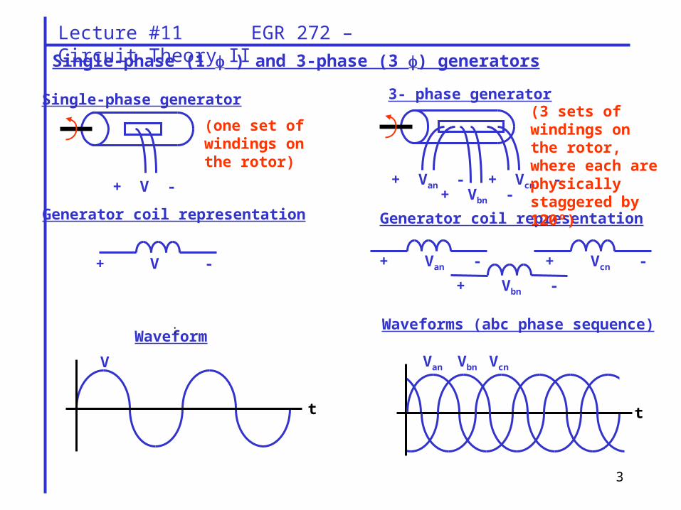
Single-phase (1 ) and 3-phase (3 ) generators
Generator coil representation
+ V -
Waveform:
t
V
Waveforms (abc phase sequence)
+ V -
Single-phase generator
+ Van - + Vbn -
+ Vcn -
3- phase generator
Generator coil representation
+ Van -
+ Vbn -
+ Vcn -
t
Van Vbn Vcn
(one set of windings on the rotor)
(3 sets of windings on the rotor, where each are physically staggered by 120º)
4
Lecture #11 EGR 272 – Circuit Theory II
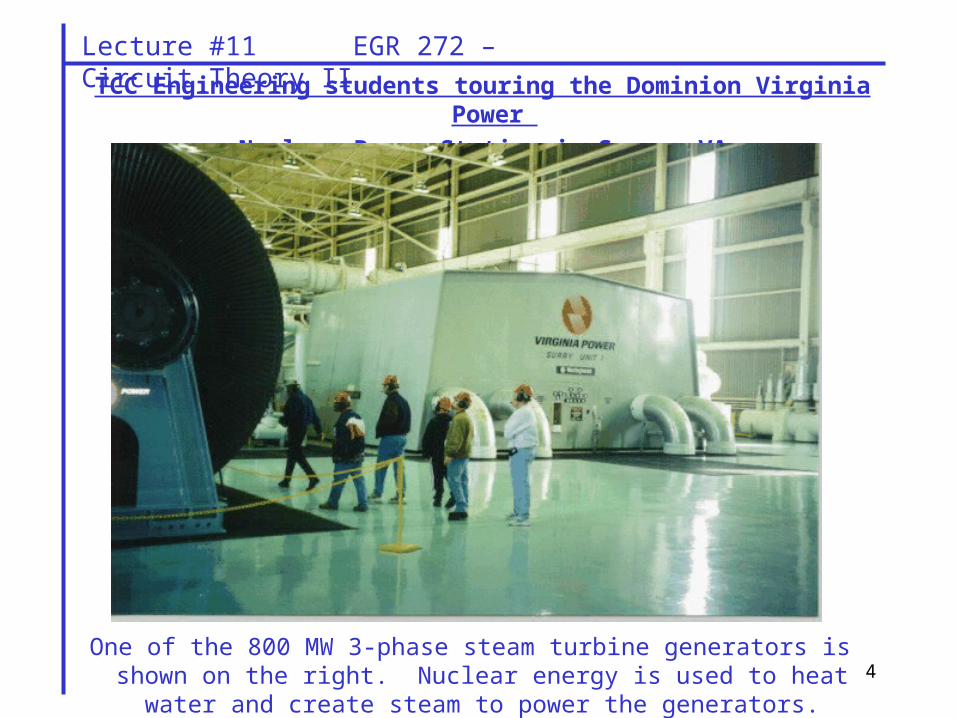
TCC Engineering students touring the Dominion Virginia Power
Nuclear Power Station in Surry, VA
One of the 800 MW 3-phase steam turbine generators is shown on the right. Nuclear energy is used to heat water and create steam to power the
generators.
5
Lecture #11 EGR 272 – Circuit Theory II
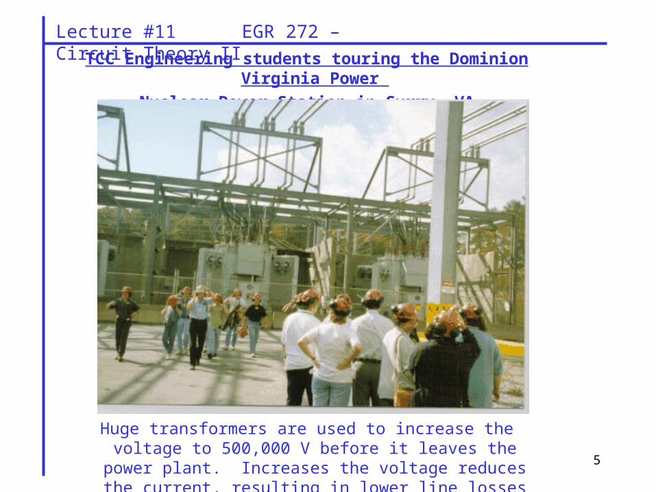
TCC Engineering students touring the Dominion Virginia Power
Nuclear Power Station in Surry, VA
Huge transformers are used to increase the voltage to 500,000 V before it leaves the power plant. Increases the voltage reduces the
current, resulting in lower line losses (I2R) during transmission.
6
Lecture #11 EGR 272 – Circuit Theory II
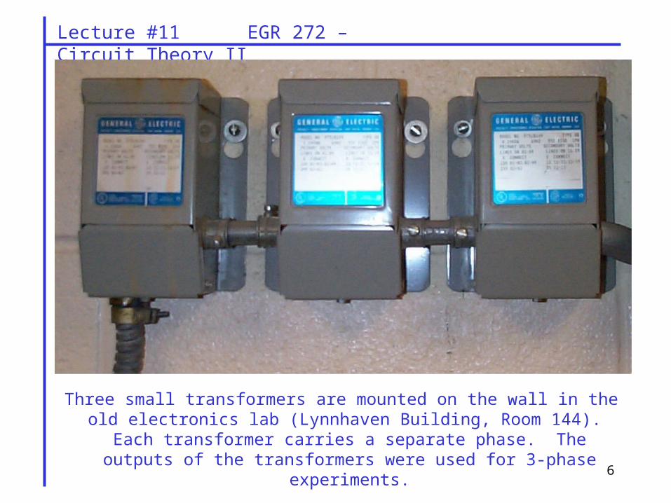
Three small transformers are mounted on the wall in the old electronics lab (Lynnhaven Building, Room 144). Each transformer carries a separate phase.
The outputs of the transformers were used for 3-phase experiments.
7
Lecture #11 EGR 272 – Circuit Theory II
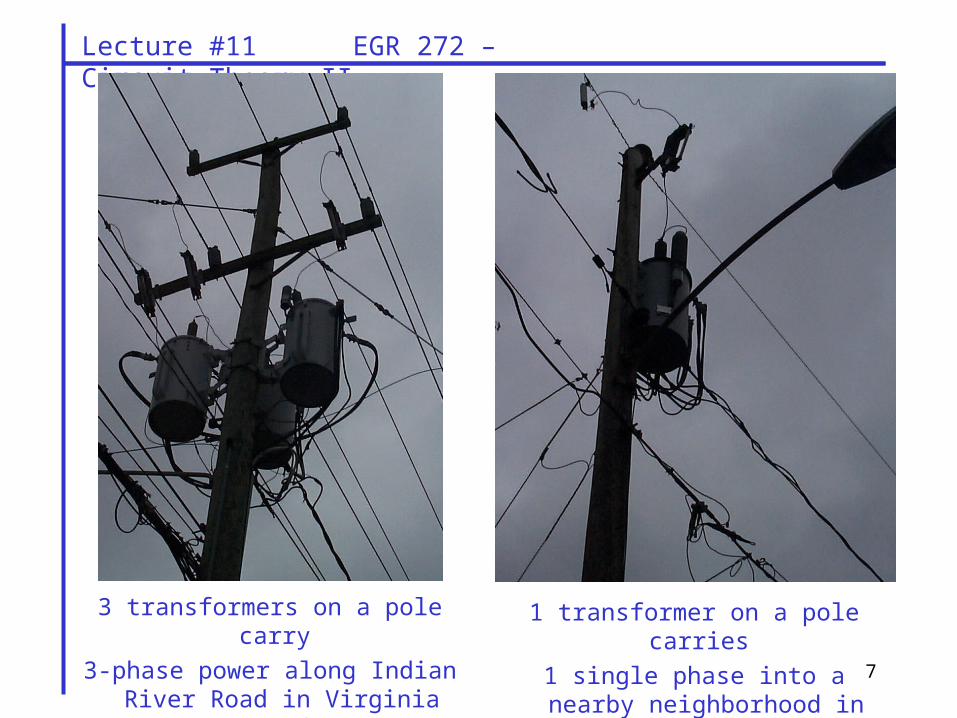
3 transformers on a pole carry
3-phase power along Indian River Road in Virginia Beach
1 transformer on a pole carries
1 single phase into a nearby neighborhood in Virginia Beach
8
Lecture #11 EGR 272 – Circuit Theory II
an p
bn p
cn p
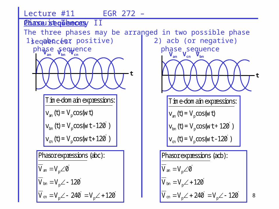
Time-domain expressions:
v (t) = V cos(wt)
v (t) = V cos(wt - 120 )
v (t) = V cos(wt 120 )
an p
bn p
cn p p
Phasor expressions (abc):
V V 0
V V 120
V V 240 V 120
1) abc (or positive) phase sequence
an p
bn p
cn p
Time-domain expressions:
v (t) = V cos(wt)
v (t) = V cos(wt + 120 )
v (t) = V cos(wt - 120 )
an p
bn p
cn p p
Phasor expressions (acb):
V V 0
V V 120
V V 240 V 120
2) acb (or negative) phase sequence
Phase sequencesThe three phases may be arranged in two possible phase sequences:
t
Van Vbn Vcn
t
Van Vcn Vbn
9
Lecture #11 EGR 272 – Circuit Theory II
180o
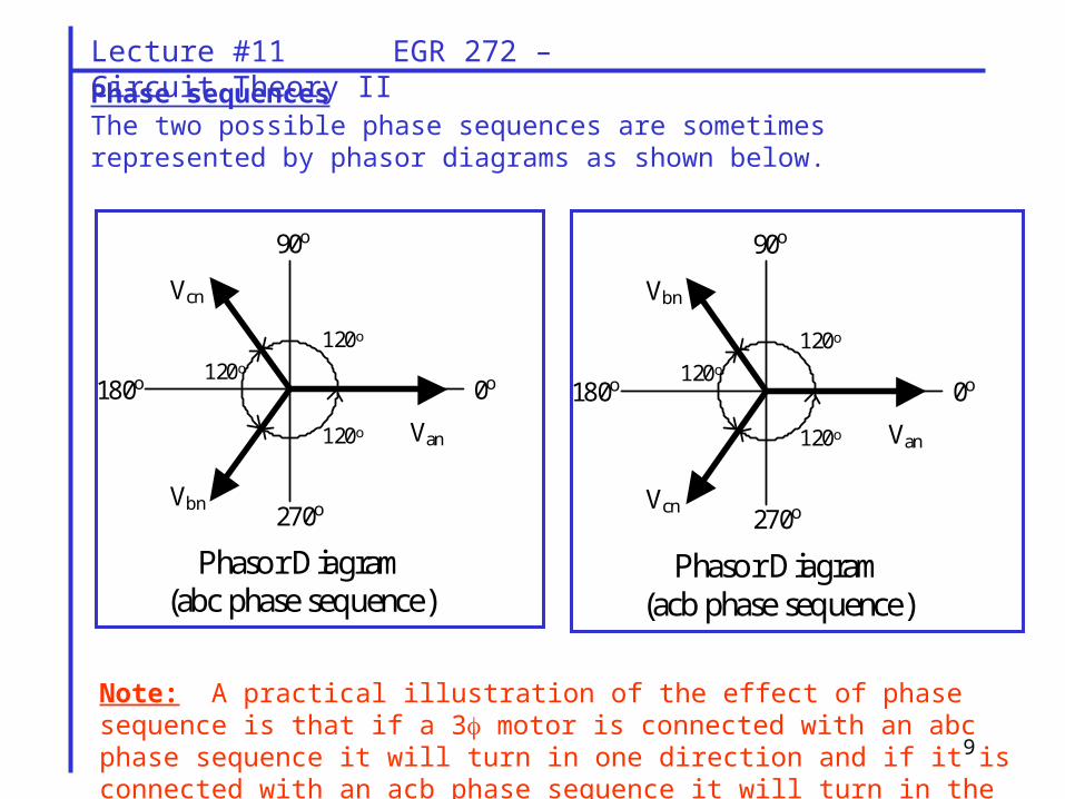
Phasor Diagram (abc phase sequence)
0o
90o
270o
Van
Vbn
Vcn
120o
120o
120o
180o
Phasor Diagram (acb phase sequence)
0o
90o
270o
Van
Vcn
Vbn
120o
120o
120o
Phase sequencesThe two possible phase sequences are sometimes represented by phasor diagrams as shown below.
Note: A practical illustration of the effect of phase sequence is that if a 3 motor is connected with an abc phase sequence it will turn in one direction and if it is connected with an acb phase sequence it will turn in the other direction.
10
Lecture #11 EGR 272 – Circuit Theory II
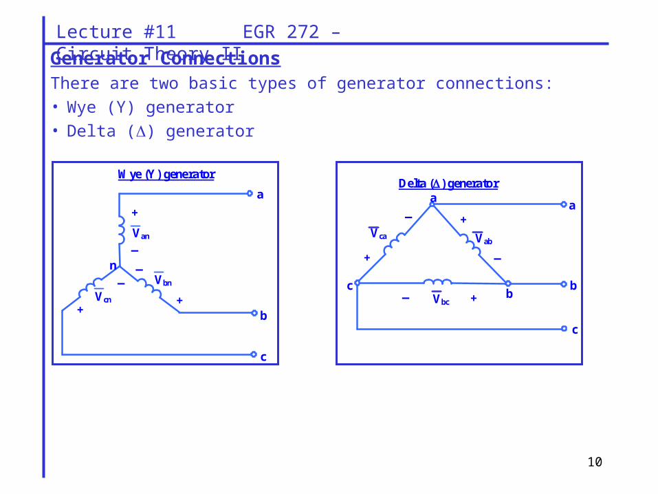
Generator ConnectionsThere are two basic types of generator connections:
• Wye (Y) generator
• Delta () generator
Wye (Y) generator
Van
+
_
_
Vcn Vbn
+ +
_
a
b
c
n
Vbc c
_ a
+
b
Vab Vca
+
+
_
_
a
b
c
Delta () generator
11
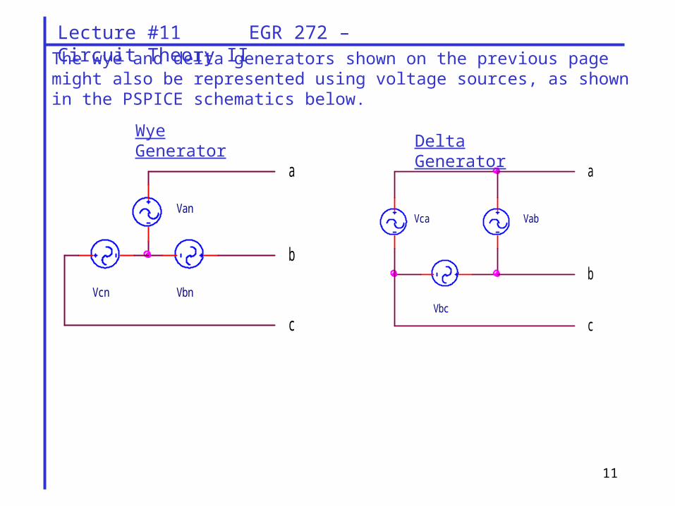
Lecture #11 EGR 272 – Circuit Theory IIThe wye and delta generators shown on the previous page might also be represented using voltage sources, as shown in the PSPICE schematics below.
Wye Generator
a
Vcn Vbn
Van
c
b
Vca
b
Vab
a
cVbc
Delta Generator
12
Lecture #11 EGR 272 – Circuit Theory II
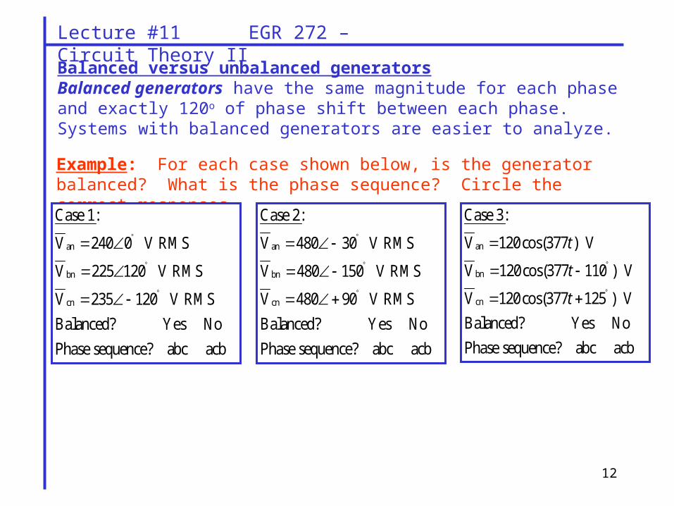
Balanced versus unbalanced generatorsBalanced generators have the same magnitude for each phase and exactly 120o of phase shift between each phase. Systems with balanced generators are easier to analyze.
Example: For each case shown below, is the generator balanced? What is the phase sequence? Circle the correct responses.
an
bn
cn
Case 1:
V 240 0 V RMS
V 225 120 V RMS
V 235 120 V RMS
Balanced? Yes No
Phase sequence? abc acb
an
bn
cn
Case 2:
V 480 30 V RMS
V 480 150 V RMS
V 480 90 V RMS
Balanced? Yes No
Phase sequence? abc acb
an
bn
cn
Case 3:
V 120cos(377 ) V
V 120cos(377 110 ) V
V 120cos(377 125 ) V
Balanced? Yes No
Phase sequence? abc acb
t
t
t
13
Lecture #11 EGR 272 – Circuit Theory II
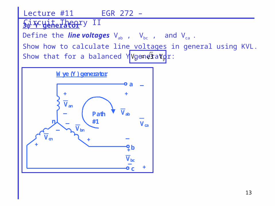
3 Y generator
Define the line voltages Vab , Vbc , and Vca .
Show how to calculate line voltages in general using KVL.
Show that for a balanced Y generator:
Wye (Y) generator
Van
+
_
_
Vcn Vbn
+ +
_
a
b
c
Vab
+
+
_
_
Path #1 n
Vbc
Vca
+
_
L pV 3 V
14
Lecture #11 EGR 272 – Circuit Theory II
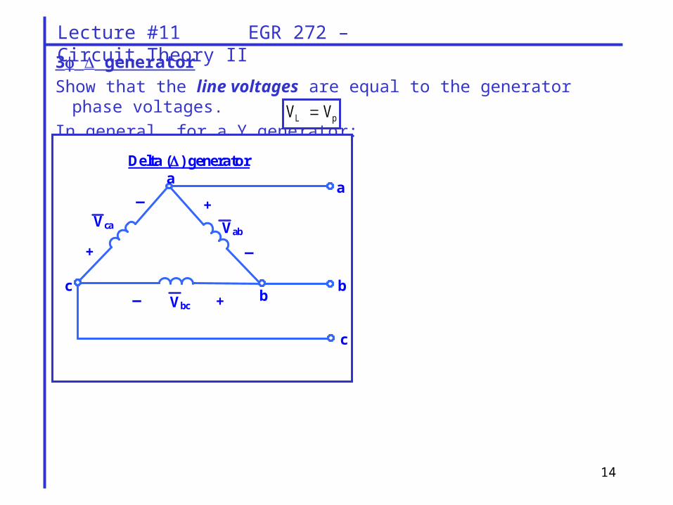
3 generator
Show that the line voltages are equal to the generator phase voltages.
In general, for a Y generator:
Vbc c
_ a
+
b
Vab Vca
+
+
_
_
a
b
c
Delta () generator
L pV V
15
Lecture #11 EGR 272 – Circuit Theory II
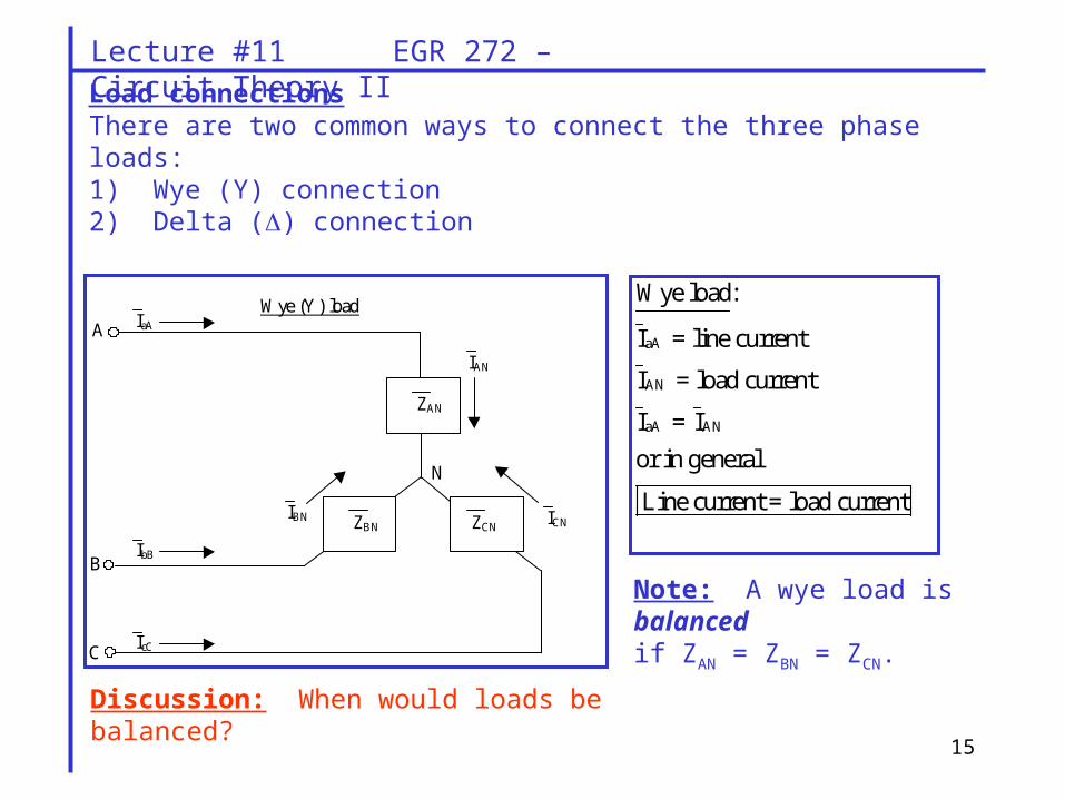
Load connectionsThere are two common ways to connect the three phase loads:1) Wye (Y) connection2) Delta () connection
Wye (Y) Load:
Wye (Y) load
ZBN
ZAN
ZCN
IbB
IcC
IaA
IAN
ICN IBN
A
B
C
N
aA
AN
aA AN
Wye load:
I = line current
I = load current
I = I
or in general
Line current = load current
Note: A wye load is balanced if ZAN = ZBN = ZCN.
Discussion: When would loads be balanced?
16
Lecture #11 EGR 272 – Circuit Theory II
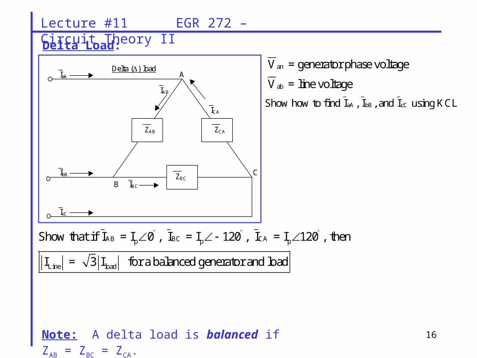
Delta Load:
an
ab
V = generator phase voltage
V = line voltage
Delta () load
ZCA ZAB
ZBC IbB
IcC
IaA
IBC
IAB
ICA
A
B
C
Note: A delta load is balanced if ZAB = ZBC = ZCA.
aA bB cCShow how to find I , I , and I using KCL
AB BC CAp p p
Line load
Show that if I = I 0 , I = I 120 , I = I 120 , then
I = 3 I for a balanced generator and load
17
Lecture #11 EGR 272 – Circuit Theory II
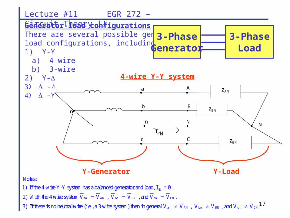
Generator-load configurations There are several possible generator andload configurations, including:1) Y-Y
a) 4-wireb) 3-wire
2) Y- --Y
3-PhaseGenerator
3-PhaseLoad
a
b
n
c
A
B
N
C
N
n
I nN
ZBN
ZAN
ZBN
4-wire Y-Y system
Y-Generator Y-Load
nN
an AN bn BN cn CN
Notes:
1) If the 4-wire Y-Y system has a balanced generator and load, I = 0.
2) With the 4 wire system V V , V V , and V V .
3) If there is no neutral wire (i.e., a 3-wire system)
an AN bn BN cn CNthen in general V V , V V , and V V .
18
Lecture #11 EGR 272 – Circuit Theory II
Example: A 4-wire Y-Y system has a balanced generator with Van = 480 V and a positive phase
sequence.A B nN
C
C
If Z Z 2 j2 , then find I if :
A) Z 2 j2 (i.e., the load is balanced)
B) Z 2 - j2 (i.e., the load is unbalanced)
19
Lecture #11 EGR 272 – Circuit Theory II
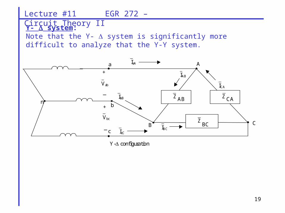
a
b
c
A
C B
n
IaA
Z CA Z AB
Z BC
_
+
IbB
IcC
ICA
IBC
IAB
Vbc
Vab
+
_
Y- configuration
Y- system:Note that the Y- system is significantly more difficult to analyze that the Y-Y system.
20
Lecture #11 EGR 272 – Circuit Theory II
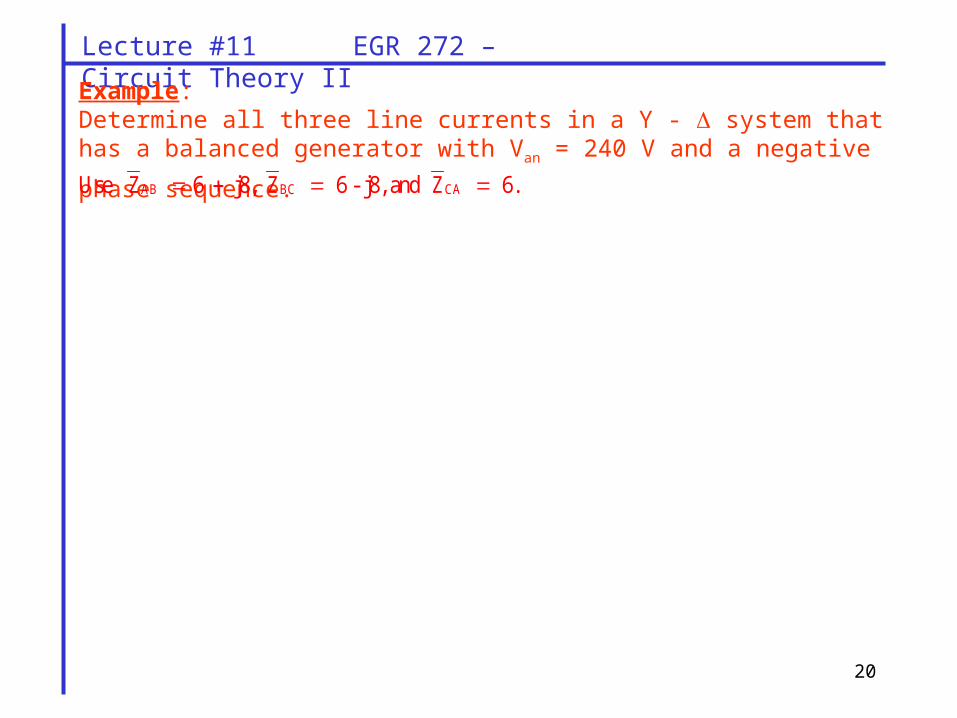
Example: Determine all three line currents in a Y - system that has a balanced generator with
Van = 240 V and a negative phase sequence. AB BC CAUse Z 6 j8, Z 6 - j8, and Z 6.