Embed Size (px)
Citation preview
1
Lecture 7:Lecture 7:Part 2: Message Passing Part 2: Message Passing
MulticomputersMulticomputers
(Distributed Memory Machines)
2
Message Passing Multicomputer Consists of multiple computing units, called nodes Each node is an autonomous computer, consists of
• Processor(s) (may be an SMP)• Local memory• Disks or I/O peripherals (optional)• full-scale OS (some microkernel)
Nodes are communicated by message passing No-remote-memory-access (NORMA) machines Distributed memory machines
3
IBM SP2
4
SP2
IBM SP2 => Scalable POWERparallel System
Developed based on RISC System/6000
architecture (POWER2 processor)
Interconnect: High-Performance Switch (HPS)
5
SP2 - NodesSP2 - Nodes 66.7 MHz POWER2 processor with L2 cache.
POWER2 can perform six instructions (2 load/store,
index increment, conditional branch, and two floating-
point) per cycle.
2 floating point units (FPU) + 2 fixed point units (FXU)
Perform up to four floating-point operations (2 multiply-
add ops) per cycle.
A peak performance of 266 Mflops (66.7 x4) can be
achieved.
6
IBM SP2 using Two types of nodes :
Thin node:
4 micro-channel (I/O) slots, 96KB L2 cache,
64-512MB memory, 1-4 GB disk
Wide node :
8 micro-channel slots, 288KB L2 cache, 64-
2048MB memory, 1-8 GB disk
7
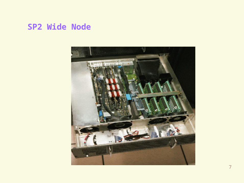
SP2 Wide Node
8
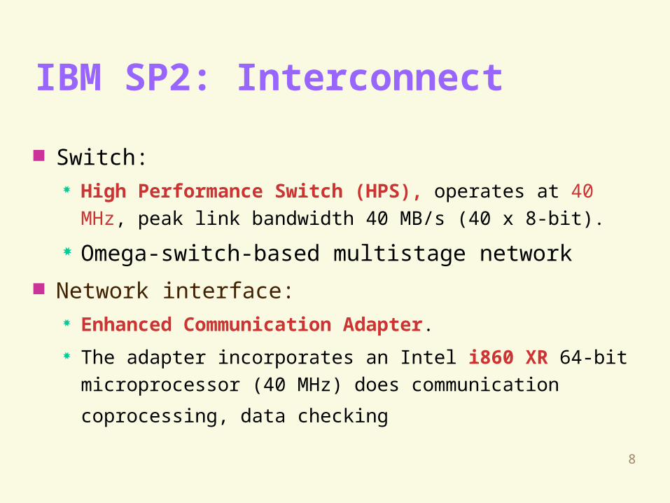
IBM SP2: Interconnect
Switch: High Performance Switch (HPS), operates at 40 MHz, peak
link bandwidth 40 MB/s (40 x 8-bit).
Omega-switch-based multistage network
Network interface: Enhanced Communication Adapter.
The adapter incorporates an Intel i860 XR 64-bit
microprocessor (40 MHz) does communication coprocessing,
data checking
9
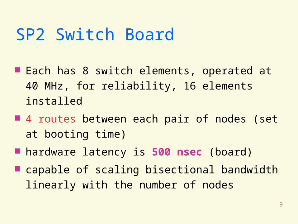
SP2 Switch Board
Each has 8 switch elements, operated at 40 MHz,
for reliability, 16 elements installed
4 routes between each pair of nodes (set at
booting time)
hardware latency is 500 nsec (board)
capable of scaling bisectional bandwidth linearly
with the number of nodes
10
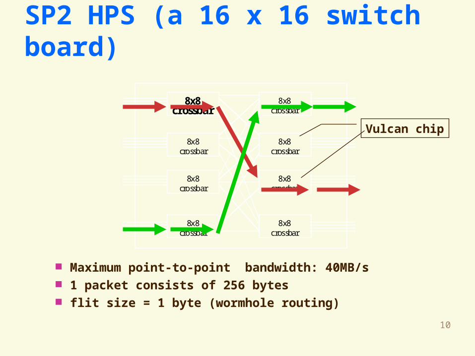
Maximum point-to-point bandwidth: 40MB/s 1 packet consists of 256 bytes flit size = 1 byte (wormhole routing)
SP2 HPS (a 16 x 16 switch board)
8x8crossbar
8x8crossbar
8x8crossbar
8x8crossbar
8x8crossbar
8x8crossbar
8x8crossbar
8x8crossbar
Vulcan chip
11
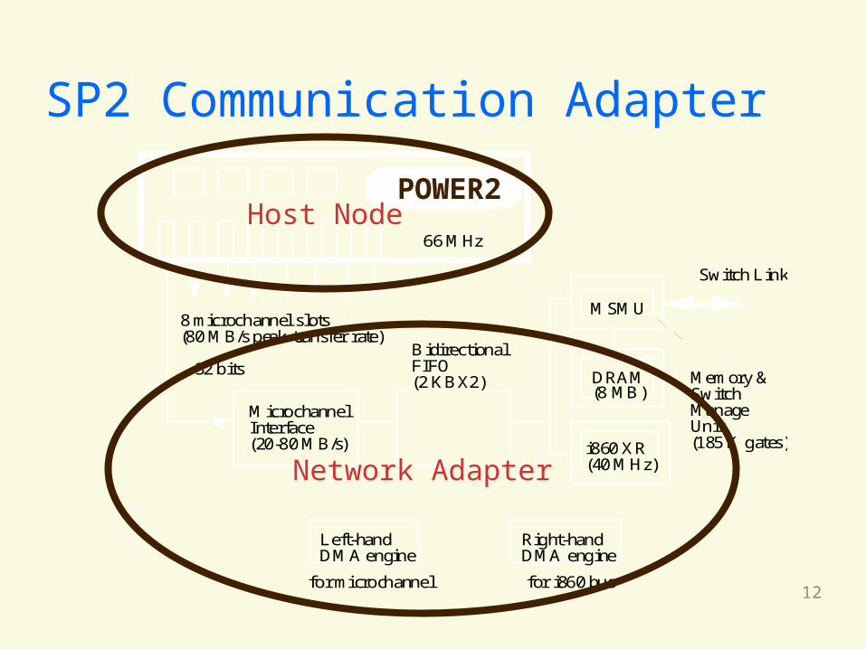
SP2 Communication Adapter
one adapter per node one switch board unit per rack send FIFO has 128 entries (256 bytes each) receive FIFO has 64 entries (256 bytes each) 2 DMA engines
12
SP2 Communication Adapter
8 microchannel slots
Microchannel Interface(20-80 MB/s)
BidirectionalFIFO(2 KBX2) DRAM
(8 MB)
MSMU
Switch Link
i860 XR(40 MHz)
(80 MB/s peak transfer rate)
32 bits
Left-handDMA engine
Right-handDMA engine
Memory & SwitchManageUnit
for microchannel for i860 bus
66 MHz
(185 K gates)
POWER2Host Node
Network Adapter
13
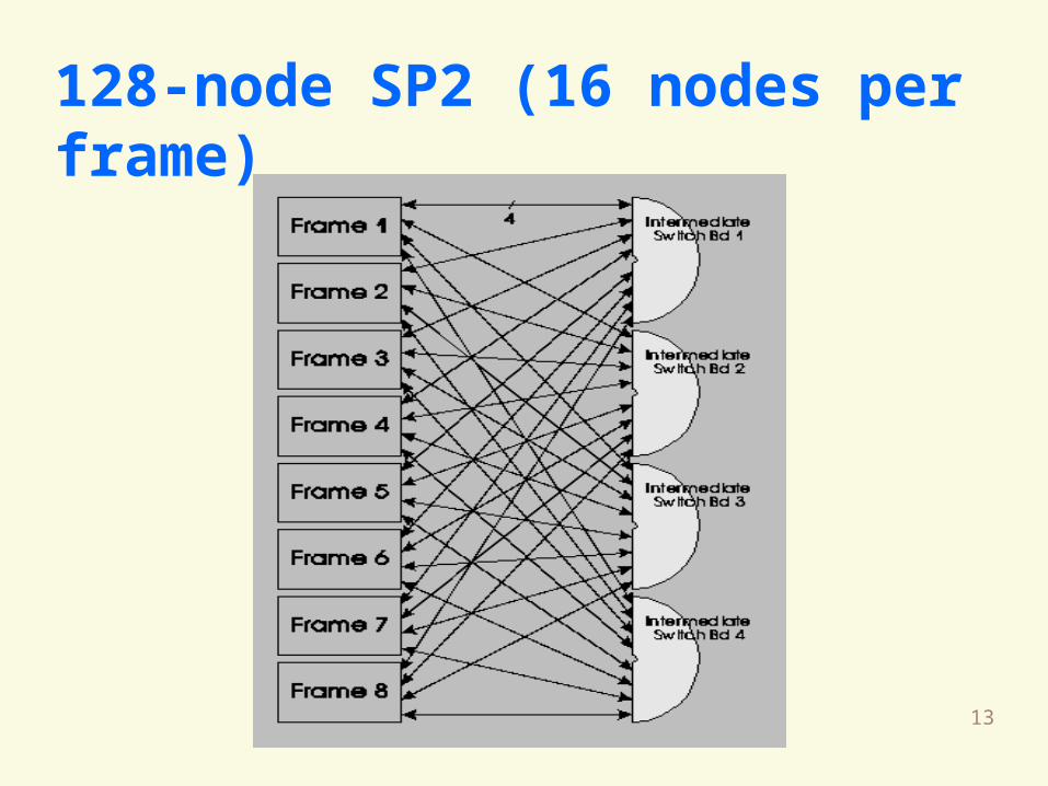
128-node SP2 (16 nodes per frame)

14
INTEL PARAGON
15
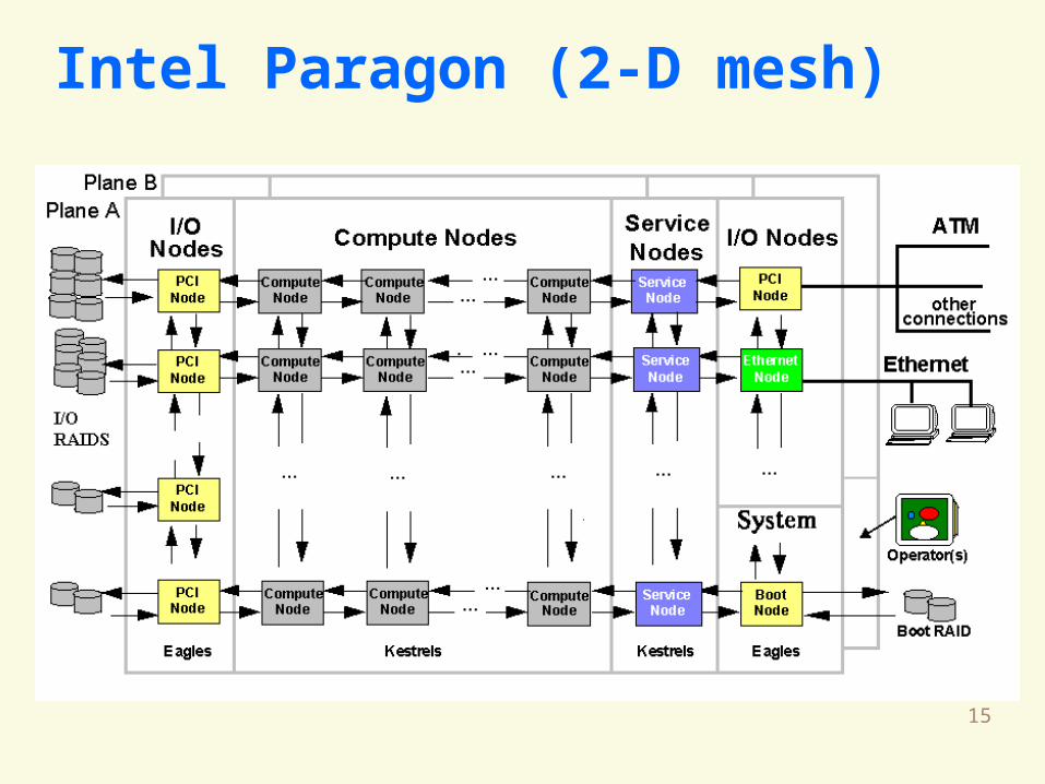
Intel Paragon (2-D mesh)
16
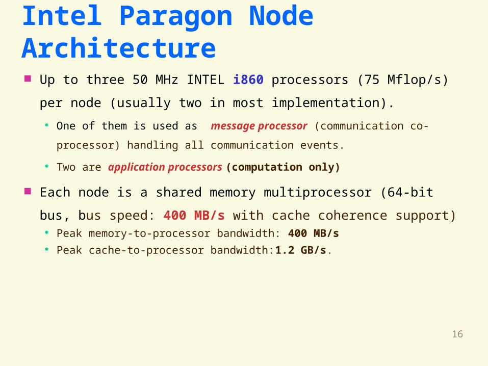
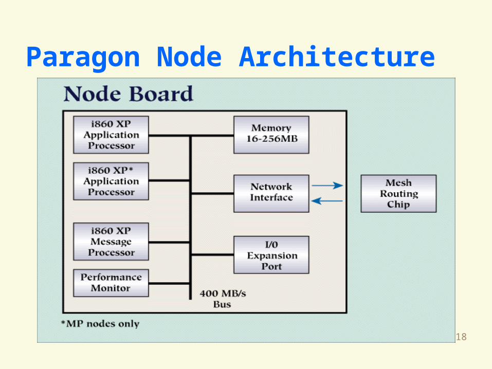
Intel Paragon Node Architecture Up to three 50 MHz INTEL i860 processors (75 Mflop/s) per
node (usually two in most implementation).
One of them is used as message processor (communication co-
processor) handling all communication events.
Two are application processors (computation only)
Each node is a shared memory multiprocessor (64-bit bus, bus
speed: 400 MB/s with cache coherence support) Peak memory-to-processor bandwidth: 400 MB/s Peak cache-to-processor bandwidth:1.2 GB/s.
17
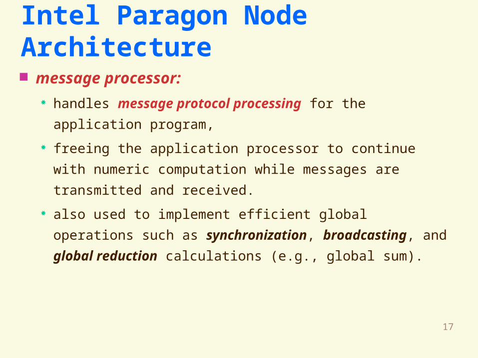
Intel Paragon Node Architecture message processor:
handles message protocol processing for the application
program,
freeing the application processor to continue with numeric
computation while messages are transmitted and received.
also used to implement efficient global operations such as
synchronization, broadcasting, and global reduction
calculations (e.g., global sum).
18
Paragon Node Architecture
19
Paragon Interconnect
2-D Mesh I/O devices attached on a single side
16-bit link, 175 MB/s
Mesh Routing Components (MRCs), one for each node.
40 nsec per hop (switch delay) and 70 nsec if changes
dimension (from x-dim to y-dim).
In a 512 PEs (16x32), 10 hops is 400-700nsec

20
CRAY T3D
21
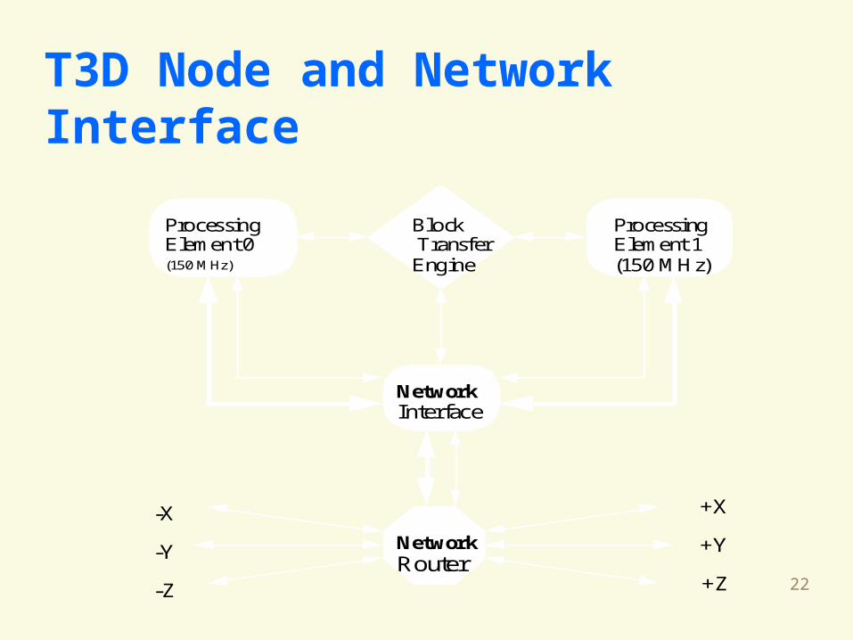
Cray T3D Node Architecture
Each processing node contains two PEs, a
network interface, and a block transfer
engine. (shared by the two PEs) PE: 150 MHz DEC 21064 Alpha AXP, 34-bit
address, 64 MB memory, 150 MFLOPS
1024 processor: sustained max speed 152
Gflop/s
22
T3D Node and Network Interface
Processing Element 0(150 MHz)
Processing Element 1(150 MHz)
Block Transfer Engine
Network Interface
Network Router
+X
+Y
+Z
-X
-Y
-Z
23
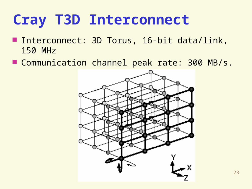
Cray T3D Interconnect Interconnect: 3D Torus, 16-bit data/link, 150 MHz Communication channel peak rate: 300 MB/s.
24
T3D
The cost of routing data between processors
through interconnect nodes is two clock cycles
(6.67 nsec per cycle) per node traversed and
one extra clock cycle to turn a corner
The overheads for using block transfer engine is
high. (startup cost > 480 cycles x 6.67 nsec = 3.2
usec)
25
T3D: Local and Remote Memory Local memory:
16 or 64 MB DRAM per PE
Latency: 13 to 38 clock cycles (87 to 253 nsec)
Bandwidth: up to 320 MB/s
Remote memory: Directly addressable by the processor,
Latency of 1 to 2 microseconds
Bandwidth: over 100 MB/s (measured in software).
26
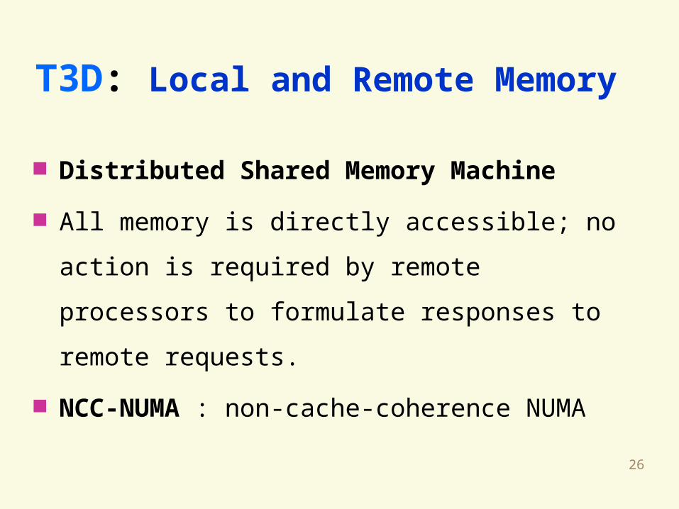
T3D: Local and Remote Memory
Distributed Shared Memory Machine
All memory is directly accessible; no action is
required by remote processors to formulate
responses to remote requests.
NCC-NUMA : non-cache-coherence NUMA
27
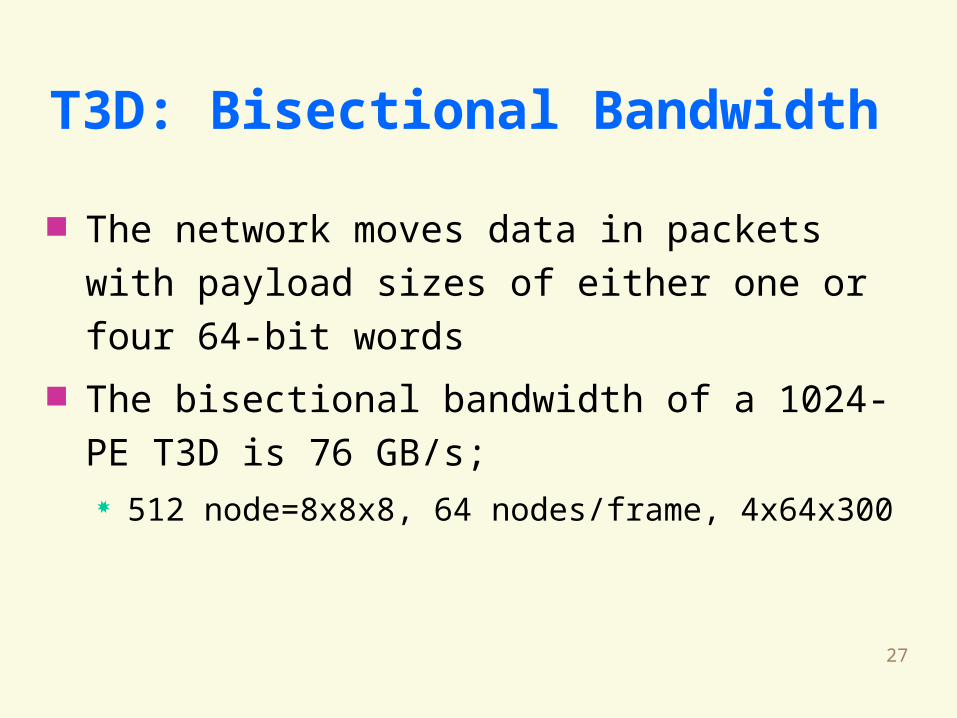
T3D: Bisectional Bandwidth
The network moves data in packets with payload
sizes of either one or four 64-bit words
The bisectional bandwidth of a 1024-PE T3D is
76 GB/s; 512 node=8x8x8, 64 nodes/frame, 4x64x300
28
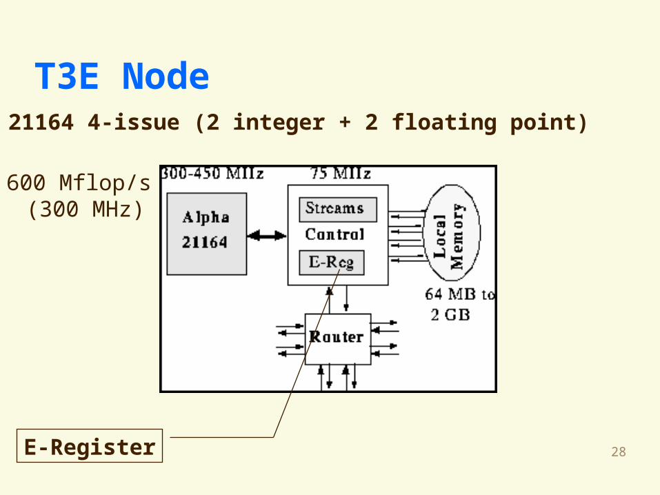
T3E Node
E-Register
Alpha 21164 4-issue (2 integer + 2 floating point)
600 Mflop/s (300 MHz)
29
Cluster:Network of Workstation
(NOW)Cluster of Workstation
(COW)Pile-of-PCs (POPC)
30
Clusters of Workstations
Several workstations which are connected by a network . connected with Fast/Gigabit Ethernet, ATM, FDDI, etc. some software to tightly integrate all resources
Each workstation is a independent machines
31
Advantages Cheaper
Easy to scale
Coarse-grain parallelism (traditionally)
Disadvantages of Clusters Longer communication latency compared with other
parallel system (traditionally)
Cluster
32
ATM Cluster (Fore SBA-200)
Cluster node : Intel Pentium II, Pentium SMP, SGI, Sun Sparc, ..
NI location: I/O bus Communication processor: Intel i960, 33MHz,
128KB RAM Peak bandwidth: 19.4 MB/s or 77.6 MB/s per
port HKU: PearlCluster (16-node), SRG DP-ATM
Cluster ($-node, 16.2 MB/s)
33
Myrinet Cluster
Cluster node: Intel Pentium II, Pentium SMP, SGI, Sun SPARC, ..
NI location: I/O bus Communication processor: LANai, 25 MHz,
128 KB SRAM Peak bandwidth: 80 MB/s --> 160 MB/s
34
Conclusion
Many current network interfaces employ a
dedicated processor to offload communication
tasks from the main processor.
Overlap computation with communication
improve performance.
35
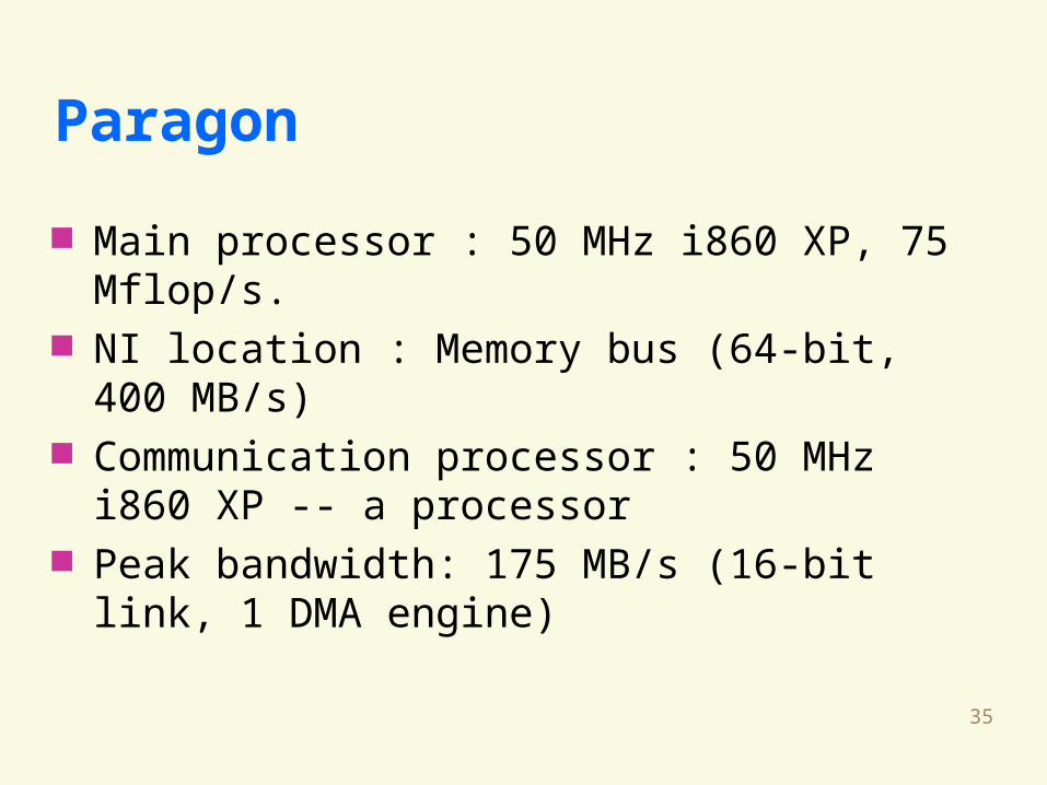
Paragon
Main processor : 50 MHz i860 XP, 75 Mflop/s. NI location : Memory bus (64-bit, 400 MB/s) Communication processor : 50 MHz i860 XP -- a
processor Peak bandwidth: 175 MB/s (16-bit link, 1 DMA
engine)
36
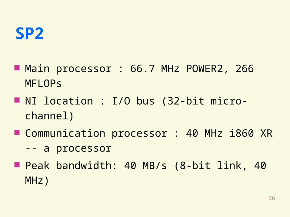
SP2
Main processor : 66.7 MHz POWER2, 266
MFLOPs
NI location : I/O bus (32-bit micro-channel)
Communication processor : 40 MHz i860 XR -- a
processor
Peak bandwidth: 40 MB/s (8-bit link, 40 MHz)
37
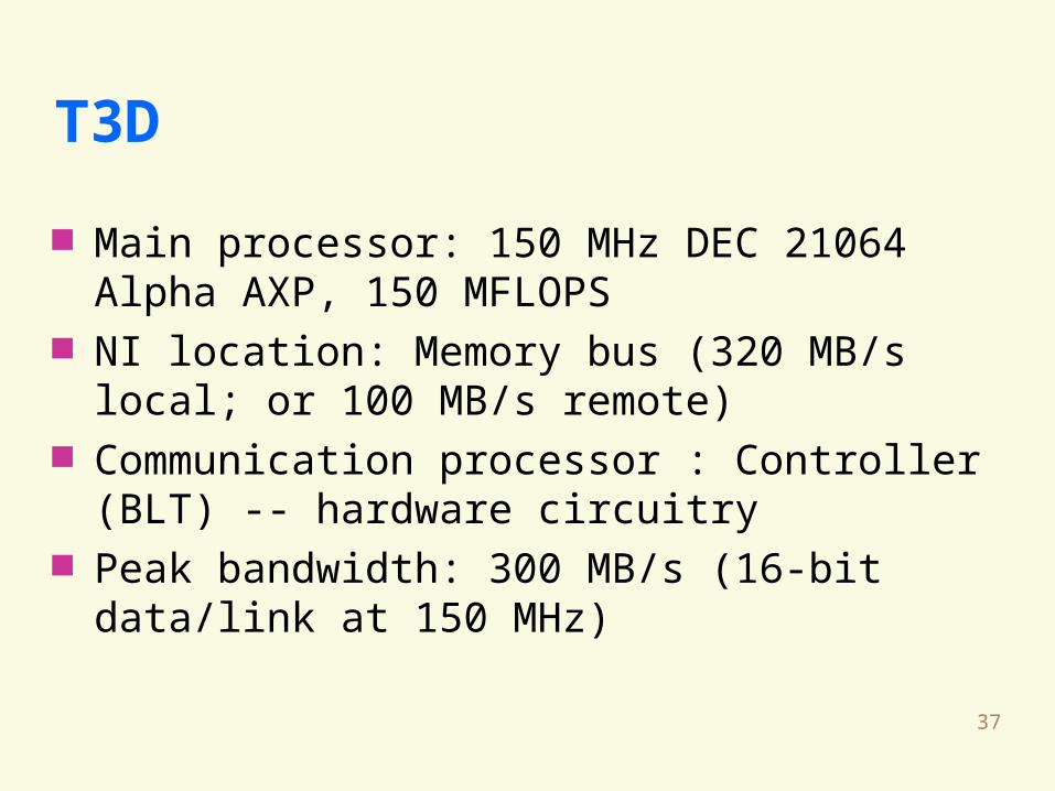
T3D
Main processor: 150 MHz DEC 21064 Alpha AXP, 150 MFLOPS
NI location: Memory bus (320 MB/s local; or 100 MB/s remote)
Communication processor : Controller (BLT) -- hardware circuitry
Peak bandwidth: 300 MB/s (16-bit data/link at 150 MHz)
![Learning Message-Passing Inference Machines for Structured ... · Contextual Classification with Functional Max-Margin Markov Networks. CVPR 2009. [5] A. Kulesza & F. Pereira. Structured](https://img.pdfslide.net/doc/110x75/5f6f1273170dbf313e581dc1/learning-message-passing-inference-machines-for-structured-contextual-classification.jpg)