Embed Size (px)
Citation preview

1
Luminosity measurement in the ATLASLuminosity measurement in the ATLASexperiment at the LHCexperiment at the LHC
26 November 2008Per GrafstromCERN

2

3
Electroweak symmetry breakingThe HiggsSuper symmetryCP-violationExtra dimensions, black holes
ATLAS

415-April-2008 ATLAS RRB4
ATLAS Collaboration
(Status April 2008)
37 Countries 167 Institutions 2200 Scientific Authors total(1750 with a PhD, for M&O share)
Albany, Alberta, NIKHEF Amsterdam, Ankara, LAPP Annecy, Argonne NL, Arizona, UT Arlington, Athens, NTU Athens, Baku, IFAE Barcelona, Belgrade, Bergen, Berkeley LBL and UC, HU Berlin, Bern, Birmingham, UAN Bogota, Bologna, Bonn, Boston, Brandeis,
Bratislava/SAS Kosice, Brookhaven NL, Buenos Aires, Bucharest, Cambridge, Carleton, Casablanca/Rabat, CERN, Chinese Cluster, Chicago, Chile, Clermont-Ferrand, Columbia, NBI Copenhagen, Cosenza, AGH UST Cracow, IFJ PAN Cracow, DESY, Dortmund, TU Dresden, JINR
Dubna, Duke, Frascati, Freiburg, Geneva, Genoa, Giessen, Glasgow, Göttingen, LPSC Grenoble, Technion Haifa, Hampton, Harvard, Heidelberg, Hiroshima, Hiroshima IT, Indiana, Innsbruck, Iowa SU, Irvine UC, Istanbul
Bogazici, KEK, Kobe, Kyoto, Kyoto UE, Lancaster, UN La Plata, Lecce, Lisbon LIP, Liverpool, Ljubljana, QMW London, RHBNC London, UC London, Lund, UA Madrid, Mainz, Manchester, Mannheim, CPPM Marseille, Massachusetts, MIT, Melbourne, Michigan, Michigan SU, Milano,
Minsk NAS, Minsk NCPHEP, Montreal, McGill Montreal, FIAN Moscow, ITEP Moscow, MEPhI Moscow, MSU Moscow, Munich LMU, MPI Munich, Nagasaki IAS, Nagoya, Naples, New Mexico, New York, Nijmegen,
BINP Novosibirsk, Ohio SU, Okayama, Oklahoma, Oklahoma SU, Oregon, LAL Orsay, Osaka, Oslo, Oxford, Paris VI and VII, Pavia, Pennsylvania, Pisa, Pittsburgh, CAS Prague, CU Prague, TU Prague, IHEP Protvino, Regina, Ritsumeikan, UFRJ Rio de Janeiro, Rome I,
Rome II, Rome III, Rutherford Appleton Laboratory, DAPNIA Saclay, Santa Cruz UC, Sheffield, Shinshu, Siegen, Simon Fraser Burnaby, SLAC, Southern Methodist Dallas, NPI Petersburg, Stockholm, KTH Stockholm, Stony Brook, Sydney,
AS Taipei, Tbilisi, Tel Aviv, Thessaloniki, Tokyo ICEPP, Tokyo MU, Toronto, TRIUMF, Tsukuba, Tufts, Udine/ICTP, Uppsala, Urbana UI, Valencia, UBC Vancouver, Victoria, Washington, Weizmann Rehovot, FH Wiener Neustadt, Wisconsin, Wuppertal, Yale, Yerevan

5
The very first Event in ATLASThe very first Event in ATLAS

6
Motivation-why we need to measure the Motivation-why we need to measure the luminosityluminosity
Measure the cross sections for “Standard “ processes Top pair production Jet production ……
New physics manifesting in deviation of x BR
relative to the Standard Model predictions. Precision measurement becomes more
important if new physics not directly seen. (characteristic scale too high!)
Important precision measurements Higgs production x BR tan measurement for MSSM Higgs ……. Relative precision on the measurement of HBR for various
channels, as function of mH, at Ldt = 300 fb–1. The dominant uncertainty is from Luminosity: 10% (open symbols), 5% (solid symbols).
(ATLAS Physics TDR , May 1999)
Theoretically known to ~ 10 %
Higgs coupling
Instantaneous LuminosityorLdt Integrated Luminosity

7
Absolute versus Relative measurementAbsolute versus Relative measurement Relative measurements or Luminosity Monitoring
Using suitable observables in existing detectors Beam condition monitor Current in Tile calorimeter PM’s Minimum bias scintillators
Using dedicated luminosity monitor LUCID
Absolute measurements Several different methods-next slide
Strategy:
1. Measure the absolute luminosity with a precise method at optimal conditions2. Calibrate luminosity monitor with this precise measurement and then use the calibrated monitor at all conditions

8
Absolute Luminosity MeasurementsAbsolute Luminosity Measurements Goal: Measure L with ≲ 3% accuracy (long term goal)
How? Three major approachesLHC Machine parameters
Rates of well-calculable processes:e.g. QED (like LEP), EW and QCD
Elastic scatteringOptical theorem: forward elastic rate + total inelastic rate:
Luminosity from Coulomb Scattering
Hybrids
Use tot measured by others
Combine machine luminosity with optical theorem
We better pursue all options
9
OutlineOutline
Methods for Absolute Measurement of Luminosity Processes with known cross sections
Machine Parameters
Elastic scattering
Methods for Relative Measurement of Luminosity LUCID

10
Two photon production of muon pairs-Two photon production of muon pairs-QEDQED
p
p
• Pure QED• Theoretically well understood• No strong interaction involving the muons• Proton-proton re-scattering can be controlled• Cross section known to better than 1 %
Muon pairs

11
Two photon production of muon pairsTwo photon production of muon pairs
+
-
Pt 3 GeV to reach
the muon chambers
Pt 6 GeV to maintain
trigger efficiency andreasonable rates
Centrally produced 2.5
Pt() 10-50 MeV
Close to back to backin (background suppression)
Muon pairs

12
BackgroundsBackgrounds
Strong interaction of a single proton
Strong interaction between colliding proton
Di-muons from Drell-Yan production
Muons from hadron decay
Muon pairs

13
Event selection-two kind of cutsEvent selection-two kind of cuts
Kinematic cuts Pt of muons are equal within 2.5 σ
of the measurement uncertainty
Good Vertex fit and no other charged track
Suppress Drell-Yan background and hadron decays
Suppresses efficiently proton excitationsand proton-proton re-scattering
Muon pairs

14
What are the difficulties ?What are the difficulties ? The resolution
The pt resolution has to be very good in order to use the Pt() 10-50 MeV cut. The rate
The kinematical constraints σ 1 pbA typical 1033/cm2/sec year 6 fb -1 and 150 fills 40 events fill Luminosity MONITORING excludedWhat about LUMINOSITY calibration?1 % statistical error more than a year of running
Efficiencies Both trigger efficiency and detector efficiency must be known
very precisely. Non trivial. Pile-up
Running at 1034/cm2/sec “vertex cut” and “no other charged track cut”will eliminate many good events
CDF result First exclusive two-photon observed in e+e-. …. but….16 events for 530 pb-1 for a σ of 1.7 pb overall efficiency 1.6 %
Summary – Muon PairsCross sections well known and thus a potentially precise method.However it seems that statistics will always be a problem.
Muon pairs

15
W and Z countingW and Z counting
∣y∣W ±
∣η∣ l±
W and Z

16
W and Z countingW and Z counting Constantly increasing precision of QCD calculations makes counting of
leptonic decays of W and Z bosons a possible way of measuring luminosity. In addition there is a very clean experimental signature through the leptonic decay channel.
The Basic formula
Ldt is the integrated luminosityN is the number of W or Z candidatesB is the number of back ground events is the efficiency for detecting W or Z decay productsa is the acceptance
th is the theoretical inclusive cross section
W and Z

17
Uncertainties on Uncertainties on thth
th is the convolution of the Parton Distribution Functions (PDF) and of the partonic cross section
The uncertainty of the partonic cross section is available to NNLO in differential form with estimated scale uncertainty below 1 % (Anastasiou et al PRD 69, 94008.)
PDF’s more controversial and complex
W and Z
18
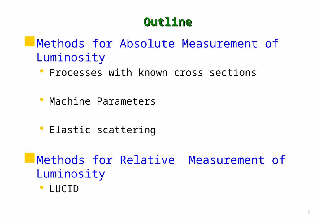
NNLO Calculations
Bands indicate the uncertainty from varying the renormalization (R) and factorization (F) scales in the range: MZ/2 < (R = F) < 2MZ
At LO: ~ 25 - 30 % x-s error At NLO: ~ 6 % x-s error At NNLO: < 1 % x-s error
Anastasiou et al., Phys.Rev. D69:094008, 2004
Perturbative expansion is stabilizing and renormalization and factorization scales reduces to level of 1 %
W and Z

19
Sensistive to x values10-1 > x > x10-4
Sea quarks and antiquark dominatesgqqbar
Gluon distribution at low x
HERA result important
x and Q2 range of PDF’s at LHCW and Z
20
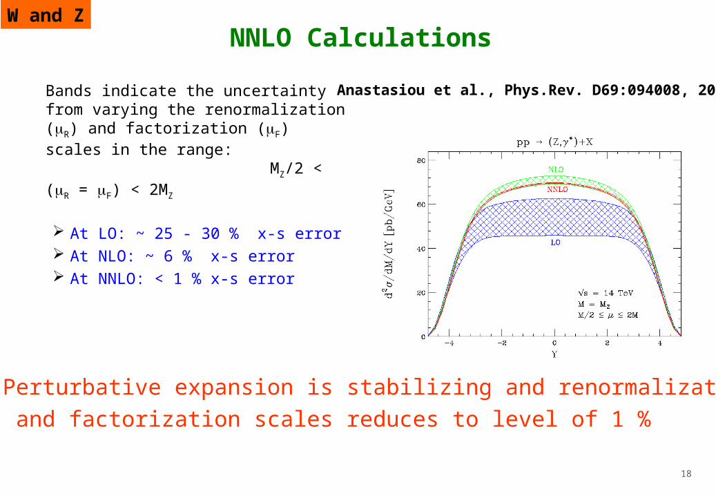
Sea(xS) and gluon (xg) PDF’sSea(xS) and gluon (xg) PDF’s
PDF uncertainties reduced enormously with HERA.Most PDF sets quote uncertainties implying errorin the W/Z cross section 5 %However central values for different sets differs sometimes more !
W and Z

21
Uncertainties in the acceptance aUncertainties in the acceptance aThe acceptance uncertainty depends on QCD theoretical error.
Generator needed to study the acceptance
The acceptance uncertainty depends on PDF,s , Initial State Radiation, intrinsic kt…..
Uncertainty estimated to about 2 -3 %
Uncertainties on
Uncertainty on trigger efficiency for isolated leptons
Uncertainty on offline reconstruction efficiencies
Estimation using tag and probe method 50 pb-1 of data 3 %
1 fb-1 < 1 %
W and Z

22
Summary – W and ZSummary – W and Z
W and Z production has a high cross section and clean experimental signature making it a good candidate for luminosity measurements.
The biggest uncertainties in the W/Z cross section comes from the PDF’s. This contribution is sometimes quoted as big as 8 % taking into account different PDF’s sets .Adding the experimental uncertainties we end up in the 10 % range.
The precision might improve considerably if the LHC data themselves can help the understanding of the differences between different parameterizations
The PDF’s will hopefully get more constrained from early LHC data .
The experimental errors will also diminish with time
Aiming at 3-5 % error in the error on the Luminosity from W/Z cross section after a couple of years of data taking.
W and Z

23
Luminosity from Machine parametersLuminosity from Machine parameters Luminosity depends exclusively on beam parameters:
Depends on frev revolution frequency
nb number of bunches
N number of particles/bunch * beam size or rather
overlap integral at IP
Machine parameters
•The luminosity is reduced if there is a crossing angle ( 300 µrad )•1 % for * = 11 m and 20% for * = 0.5 m

24
Luminosity accuracy limited by
extrapolation of x, y (or , x*, y*) from measurements of beam profiles elsewhere to IP; knowledge of optics
Precision in the measurement of the bunch current
beam-beam effects at IP, effect of crossing angle at IP, …
Machine parameters

25
What means special effort?What means special effort?
Calibration runs with simplified LHC conditions
Reduced intensity Fewer bunches No crossing angle Larger beam size ….
Simplified conditions that will optimize the condition for an accurate determination of both the beam sizes (overlap integral) and the bunch current.
Calibrate the relative beam monitors of the experiments during those dedicated calibration runs.
Machine parameters

26
Determination of the overlap integralDetermination of the overlap integral(pioneered by Van der Meer @ISR)(pioneered by Van der Meer @ISR)
Machine parameters
27
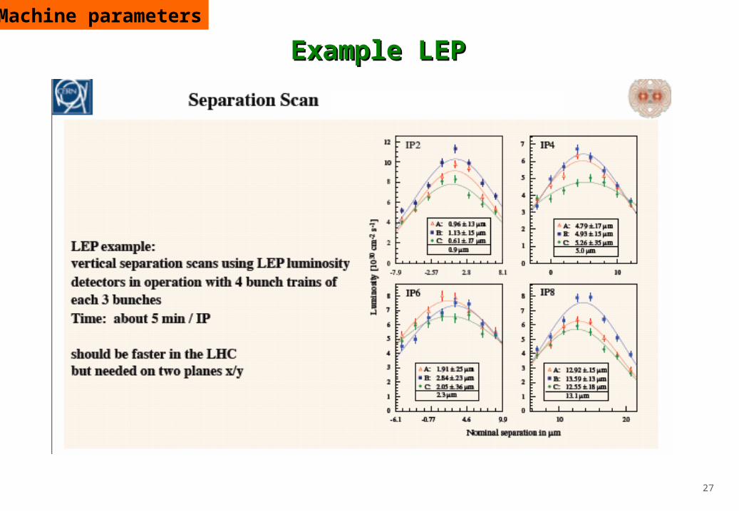
Example LEP Example LEP Machine parameters
28
Summary – Summary – MachineMachine parameters parameters
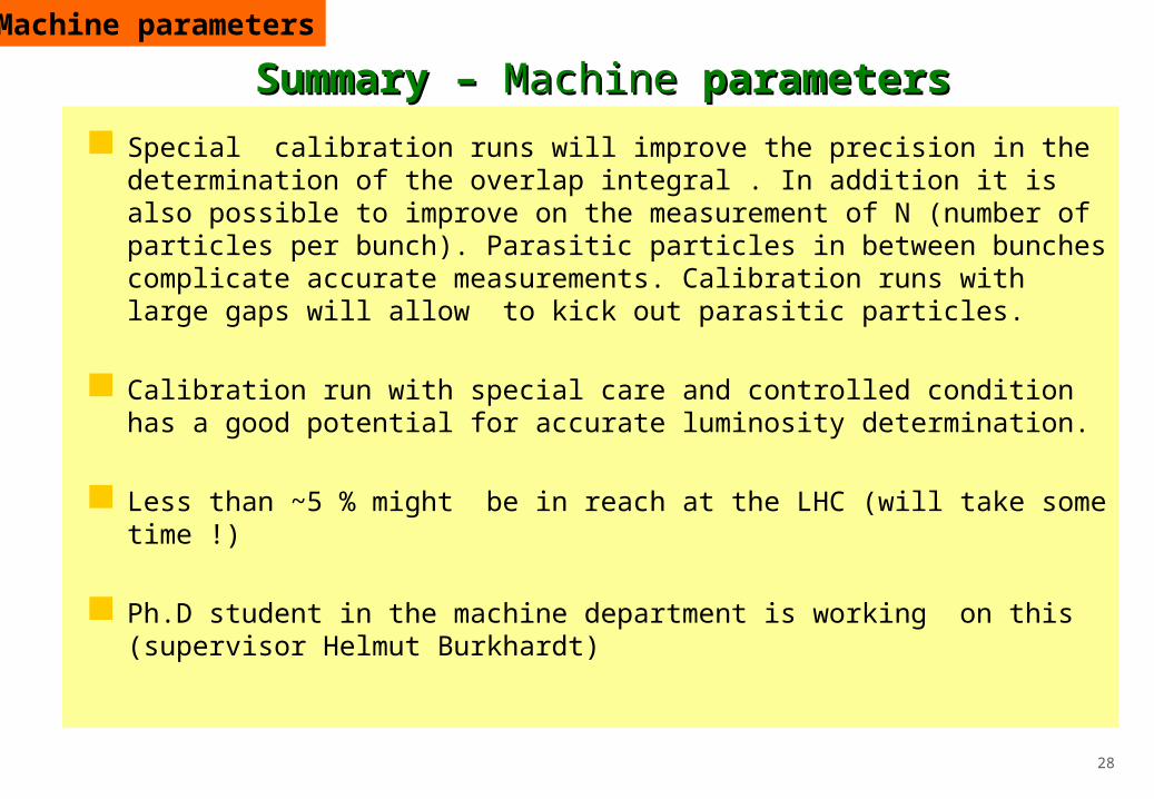
Special calibration runs will improve the precision in the determination of the overlap integral . In addition it is also possible to improve on the measurement of N (number of particles per bunch). Parasitic particles in between bunches complicate accurate measurements. Calibration runs with large gaps will allow to kick out parasitic particles.
Calibration run with special care and controlled condition has a good potential for accurate luminosity determination.
Less than ~5 % might be in reach at the LHC (will take some time !)
Ph.D student in the machine department is working on this (supervisor Helmut Burkhardt)
Machine parameters

29
Elastic scattering and luminosityElastic scattering and luminosity
Elastic scattering has traditionally provided a handle on luminosity at colliders.
Optical theorem
σtot = 4π Im fel (0)
The basis for this is the Optical Theorem which relates the total cross-section to the forward elastic scattering amplitude
The optical theorem is a general law of wave scattering theory derived from conservation of probability using quantum mechanics. It is a reflection of the fact that the very existence of scattering requires scattering in the forward direction in order to interfere with the incident wave, and thereby reduce the probability
current in this direction.

30
The Optical theorem can be used in several ways for luminosity determination.
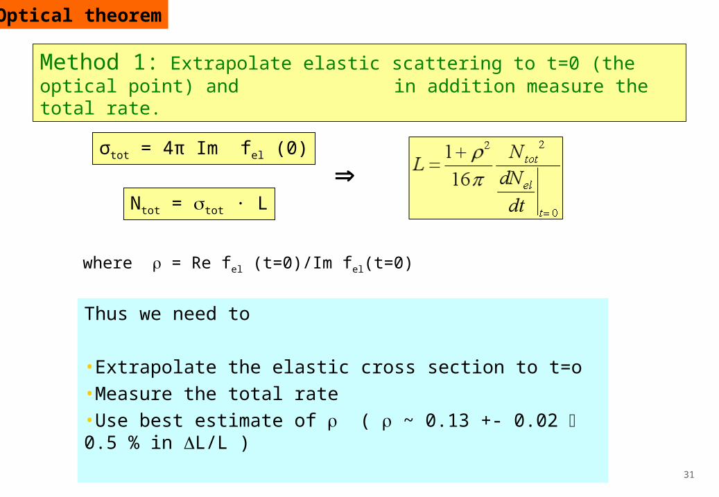
Method 1Extrapolate elastic scattering to t=0 (the optical point) and in addition measure the total rate.
Method 2 Extrapolate elastic scattering to t=0 and use a measurement
of total from another experiment.
Method 3Measure elastic scattering as such small angles that
the cross section is also sensitive to the Coulomb part.
Optical theorem
31
Optical theorem
σtot = 4π Im fel (0)
Ntot = tot · L
where = Re fel (t=0)/Im fel(t=0)
Thus we need to
•Extrapolate the elastic cross section to t=o•Measure the total rate•Use best estimate of ( ~ 0.13 +- 0.02 0.5 % in L/L )
Method 1: Extrapolate elastic scattering to t=0 (the optical point) and in addition measure the total rate.

32
Extrapolate to t=0
Exponential region
Optical theorem

33
Measure the total rateMeasure the total rate
Ntotal=Nel +Ninel
Ninel = Nnd
+Nsd+Ndd
Trigger efficiencies with MBTS
ATLAS covers an range up to 5
Optical theorem
ND 99 %DD 54%SD 45 %

34
Measure the total rate (cont.)Measure the total rate (cont.)
PHOJET 7 % of the total rate not triggered
PHYTIA12.5 % of the total rate not triggered
Taking this as extremes we would have a 5 % error in estimates of the total rate and this dominates and gives us about 10 % error in Luminosity
Optical theorem
Tuning PHOJET or PYTHIA with real data (here ALFA will be important)will improve this considerably….however difficult to be quantitative withoutsimulations. Theses studies have started.
If the diffractive rate could be estimated at the 10% level the total rateestimate would be at the level of 2% and the luminosity number could be better than 5 %

35
* uncertainty 0.13 +- .02 0.5 % in L*extrapolation to t =0 1 % in L * tot from Totem 1-2 % 2-4 % in L
5 % in luminosity possible
Method 2: Extrapolate to t=0 and use the optical theorem in combination with and independent measurement of tot
Optical theorem

36
Method 3: Optical theorem and measuring of elastic scattering at very small angles
Measure elastic scattering at such small t-values that the cross section becomes sensitive to the Coulomb amplitude
Effectively a normalization of the luminosity to the exactlycalculable Coulomb amplitude
No total rate measurement needed
UA4 used this method to determine the luminosity to 2-3 %
Coulomb

37
Elastic scattering at very small anglesElastic scattering at very small anglesCoulomb
38
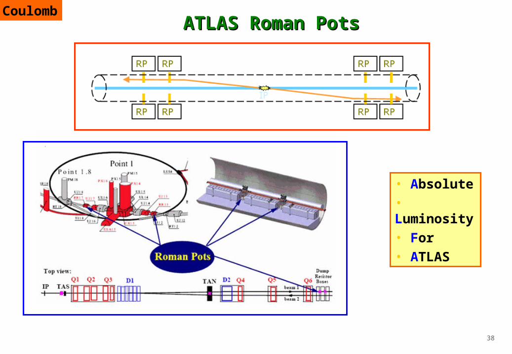
ATLAS Roman PotsATLAS Roman Pots
• Absolute• Luminosity• For • ATLAS
Coulomb

39
What is needed for the small angle elastic What is needed for the small angle elastic scattering measurements?scattering measurements?
Special beam conditions
“Edgeless” Detector
Compact electronics
Precision Mechanics in the form of Roman Pots to approach the beam
Coulomb

40
Mechanics - the pot itselfMechanics - the pot itself
ATLASspecific
Roman Pot concept
Coulomb
Beam

41
Mechanics - the Roman Pot unitMechanics - the Roman Pot unit
Profiting fromAB collimation group
Reproducible and precisemovements required
Coulomb

42
The detectors-fiber trackerThe detectors-fiber tracker
Choice of technology:• minimum dead space• no sensitivity to EM induction from beam• resolution ~ 30 m
Concept• 2x10 U planes 2x10 V planes• Scintillating fibers 0.5 mm2 squared• 64 fibers per plane• Staggered planes• MAPMT readout
Coulomb

43
Test beam campaigns-DESY and CERNTest beam campaigns-DESY and CERN
ALFA
A number of prototypes withlimited amount of fibers were tested
Main results:• Light yield ~ 4 p.e.• resolution ~ 25 m• non-active edge 100 m
Coulomb

44
The ALFA electronicsThe ALFA electronics
ATLAS
TDAQ
Coulomb

45
The ALFA electronics – front end - PMFThe ALFA electronics – front end - PMF
Adjustable amplifier-MAPMT Adjustable threshold High speedSmall cross talk Compact
Requirements
Coulomb

46
The beam conditionsThe beam conditionsNominal divergence of LHC is 32 rad We are interested in angles ~ x 10 smaller high beta optics and small emittance(divergence / β* )
y*
y*
parallel-to-point focusingydet
IP Leff
Zero crossing angle fewer bunches
Insensitive to vertex smearinglarge effective lever arm Leff
To reach the Coulomb interference region we willuse an optics with β* ~ 2.6 km and N ~ 1 m rad
β [m
]
D [m
]
Compatiblewith TOTEM
High β* and few bunches low luminosity
Coulomb
Amount of beam halo very important

47
Summary - CoulombSummary - Coulomb Getting the Luminosity through Coulomb normalization will be extremely
challenging due to the small angles and the required closeness to the beam.
Main challenge is not in the detectors but rather in the required beam properties
Will the optics properties of the beam be know to the required precision?
Will it be possible to decrease the emittance as much as we need?
Will the beam halo allow approaches in the mm range?
No definite answers before LHC start up
UA4 achieved a precision using this method at the level of 2-3 %but at the LHC it will be harder .....
Coulomb

48
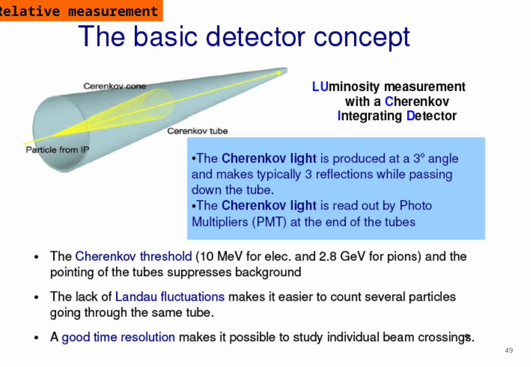
Measure the LHC luminosity.
Count the number of charged particles per BX, pointing to the primary pp interactions.
LUCID in ATLASLUCID in ATLAS
Monte Carlo simulationTwo symmetrical arms at17 m from the pp interaction
region.
Relative measurement
49
Relative measurement

50
LUCID locationLUCID location
Expected dose: 7 Mrad/year @ higest luminosity (1034 cm-2s-1)
Relative measurement

51
LUCID detectorLUCID detector
Array of mechanically polished Aluminum tubes in a Cherenkov gas (C4F10).
CC44FF1010 pressure mantained at 1.25/1.5 bar (Leak <10 mbar/day). pressure mantained at 1.25/1.5 bar (Leak <10 mbar/day).
coverage: 5.6, 6.0
Relative measurement
52
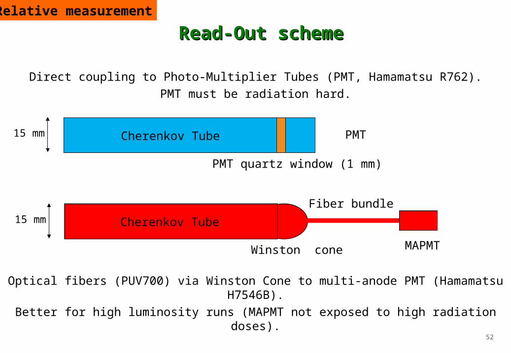
Optical fibers (PUV700) via Winston Cone to multi-anode PMT (Hamamatsu H7546B).
Better for high luminosity runs (MAPMT not exposed to high radiation doses).
Direct coupling to Photo-Multiplier Tubes (PMT, Hamamatsu R762).PMT must be radiation hard.
Cherenkov Tube PMT
PMT quartz window (1 mm)
Cherenkov Tube
MAPMTWinston cone
Fiber bundle
15 mm
15 mm
Relative measurement
Read-Out schemeRead-Out scheme

53
Overall conclusionsOverall conclusions
To start with we will work with LHC Machine parameters In the beginning 20-25 % precision.
Special calibration runs with simplified conditions will improve :
maybe 10 % after some time and then gradually towards 5 %
Rates of well-calculable processes will be next step: Two photon production of muon pairs have a low cross section
EW processes like W/Z production are good candidates:
high cross section and clean signature
QCD NNLO corrections to the partonic cross section have been
calculated and the scale error is less than 1 %
PDF’s more problematic 5-8 %
Taking into account experimental error a precision of 10 % in L might be reached
quite early
Aiming at 3- 5 % after some time - LHC data itself might constrain the PDF
Ultimate goal in ATLAS: Measure L with ~ 3 % accuracy
How do we get there?
54
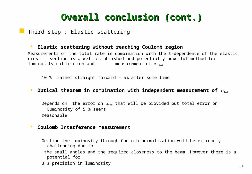
Overall conclusion (cont.)Overall conclusion (cont.) Third step : Elastic scattering
Elastic scattering without reaching Coulomb regionMeasurements of the total rate in combination with the t-dependence of the elastic
cross section is a well established and potentially powerful method for luminosity calibration and measurement of tot
10 % rather straight forward – 5% after some time
Optical theorem in combination with independent measurement of tot
Depends on the error on tot that will be provided but total error on Luminosity of 5 % seems
reasonable
Coulomb Interference measurement
Getting the Luminosity through Coulomb normalization will be extremely challenging due to
the small angles and the required closeness to the beam .However there is a potential for
3 % precision in luminosity

55
Back up

56
Overall conclusion (cont.)Overall conclusion (cont.) ATLAS proposes to use scintillating fibers in Roman Pots to measure
Elastic Scattering at small angles.
The ultimate goal is to reach the Coulomb interference region. This will be extremely challenging due to the small angles and the required closeness to the beam.
Main challenge is not so much in the detectors but rather in the required beam properties. Especially the level of beam halo at small distances will be important.
The ALFA project will be an important part of the luminosity determination in ATLAS even if the Coulomb Interference region is not completely reached.
In addition, ALFA opens up the door for a Forward Physics program in ATLAS. Experience with working close to the beam will prepare us for expanding towards a Forward Physics program as a future upgrade.

57
Hit pattern and acceptanceHit pattern and acceptanceCoulomb

58
Error evaluation as in csc notes and gueillemin article Error evaluation for pdf’s Tords comment

59
Performance simulationPerformance simulationCoulomb
60
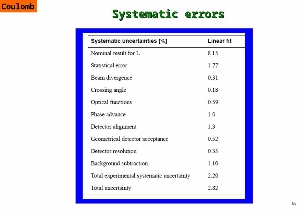
Systematic errorsSystematic errorsCoulomb

61
Statistical results from fitStatistical results from fit
• 10 M events corresponding
to 100 hours at L= 1027
• Edge 1.5 mm from beam
dNdt
∣t≈0=Lπ∣f Cf N∣2≈Lπ∣−
2aEM
∣t∣
σtot
4π iρ e
−b∣t∣
2∣2
4.30.140.15
0.2517.918B (Gev-2)
0.9101.1101tot ( mb )
1.88.158.10L (1026 cm-2 s-1 )
Error (%)Lin.fitInput
Coulomb

62
Machine induced backgroundMachine induced background
Multiple Sources
• Beam gas scattering in the arcs• Local beam gas• Inefficiencies of collimation system
Summary: 2kHz integrated above 10
Important and difficult• determines how close we can come• backgrounds estimate often wrong
Coulomb

63
Machine induced background (cont.)Machine induced background (cont.)
Main handles:
Elastic signature:• left –right coincidence• acollinearity cut
Vertex cut
Background reduced to 2 % of the elastic signal
Single diffractive background
(generated with PYTHIA )negligible : 1 permille
Coulomb

64
Vertex reconstruction for background Vertex reconstruction for background rejectionrejection
Coulomb

65
The overlap The overlap detectordetector concept conceptCoulomb

66
MAROC2 chip bonded at CERN

67
Test beam-this summerTest beam-this summer
Complete detector for one Roman Pot i.e. 1460 channels
Coulomb

68
The ATLAS DetectorThe ATLAS Detector
GeV
10%( , ) 0.3%
/E eE E
GeV
60mrad
/E
GeV
4 ns
/t E
GeV
50%( ) 3%
/E
E E
GeV
50%( jet) 2%
/E
E E
Calorimetry:
TAS
R
50 1 2 43 6 7 8
Barrel
FCAL LUCIDTracking
EndCapRP
ZDC/TAN
Diffraction/Proton Tagging Region
y109
-chambers
GeV(Inner Det) (0.03 / 1.2)%TT
pp
Tracking:
GeV(IDet+ ) (0.009 / 1.4)%TT
pp

69
Luminosity Measurement (cont.)Luminosity Measurement (cont.)
Relative precision on the measurement of HBR for various channels, as function of mH, at Ldt = 300 fb–1. The dominant uncertainty is from Luminosity: 10% (open symbols), 5% (solid symbols).
(ATLAS-TDR-15, May 1999)
Higgs coupling tan measurement
ExamplesExamples
Systematic error dominated by luminosity (ATLAS Physics TDR )