Embed Size (px)
Citation preview
1M
KU
Tracker Alignment Strategies for ATLAS and CMS
Muge Karagoz UnelOn behalf of ATLAS and CMS Alignment Groups
12th April 2007UK HEP Forum – LHC StartupCosener's House, Abingdon
AT
LA
S &
CM
S A
lign
me
nt
2M
KU
Contents
Will try to cover…• Motivations for alignment• The experiments and detectors• Alignment Performances• The current status and plans for early data
Disclaimer: Will concentrate mostly on inner tracker alignment and make use of ATLAS.
Note: most trigger plans & early physics issues will be described by the other speakers.
AT
LA
S &
CM
S A
lign
me
nt
3M
KU
the PrerequisitesA
TL
AS
& C
MS
Alig
nm
en
t
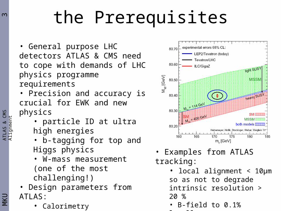
• General purpose LHC detectors ATLAS & CMS need to cope with demands of LHC physics programme requirements• Precision and accuracy is crucial for EWK and new physics
• particle ID at ultra high energies • b-tagging for top and Higgs physics• W-mass measurement (one of the most challenging!)
• Design parameters from ATLAS:• Calorimetry
• , for electrons
• Tracking• pT/pT, for muons of 500 GeV
• Examples from ATLAS tracking: • local alignment < 10μm so as not to degrade intrinsic resolution > 20 %• B-field to 0.1% locally• material globally to 1%
4M
KU
the ATLAS DetectorA
TL
AS
& C
MS
Alig
nm
en
t
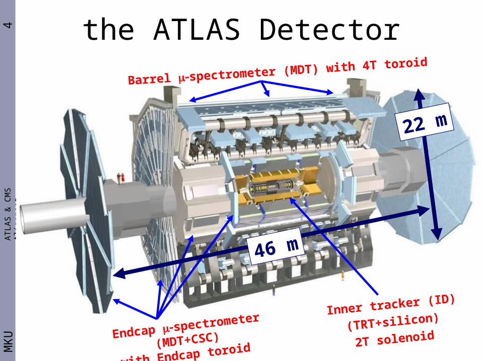
Inner tracker (ID)
(TRT+silicon)
2T solenoid
Barrel spectrometer (MDT) with 4T toroid
Endcap spectrometer (MDT+CSC)
with Endcap toroid
46 m
22 m
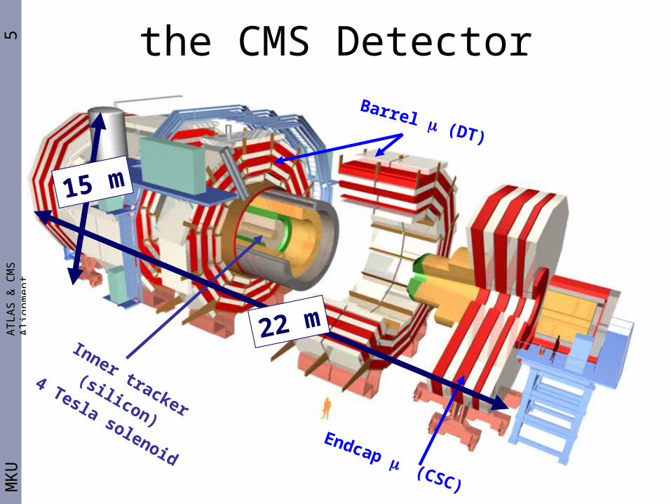
5M
KU
the CMS DetectorA
TL
AS
& C
MS
Alig
nm
en
t
Inner tracker (silicon)
4 Tesla solenoid
Barrel (DT)
Endcap (CSC)
22 m
15 m

6M
KU
AT
LA
S &
CM
S A
lign
me
nt
SCT barrels: 4 layers
SCT endcaps: 9 disks
Pixels (3 layers+3 disks)
TRT
Barrel TRT
Forward TRT
Barrel
Silicon
Forward
Silicon
SubDetector A/B/C PIX SCT PIX SCT
# layers/disks/wheels 3 2x(12/8/8) 3 4 2x3 2x9
# modules/planes 32 2x8 1456 2112 2x144 2x988
sub Total 96 448 3568 2264
Total 544 5832
6 DoF/module:3 translations& 3 rotations
the Challenge: Atlas ID is BIG
• Silicon total DoF = 6x 5832 = 34992!• TRT total DoF = 7x96 + 6x56= 1008
5.4 m
Alignment challenge!
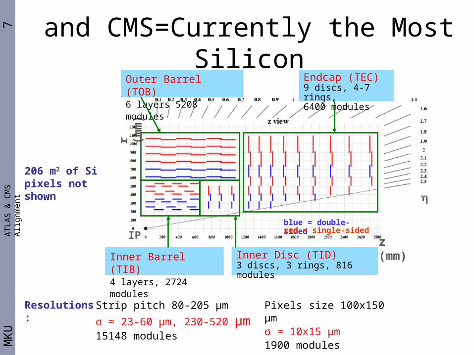
7M
KU
AT
LA
S &
CM
S A
lign
me
nt
and CMS=Currently the Most Silicon
206 m2 of Sipixels not shown
Strip pitch 80-205 µm
σ ≈ 23-60 µm, 230-520 µm 15148 modules
Pixels size 100x150 µmσ ≈ 10x15 µm 1900 modules
IP
z (mm)
r (m
m)
blue = double-sidedred = single-sided
Endcap (TEC)9 discs, 4-7 rings, 6400 modules
Inner Disc (TID)3 discs, 3 rings, 816 modules
Outer Barrel (TOB)6 layers 5208 modules
Inner Barrel (TIB)4 layers, 2724 modules
Resolutions:
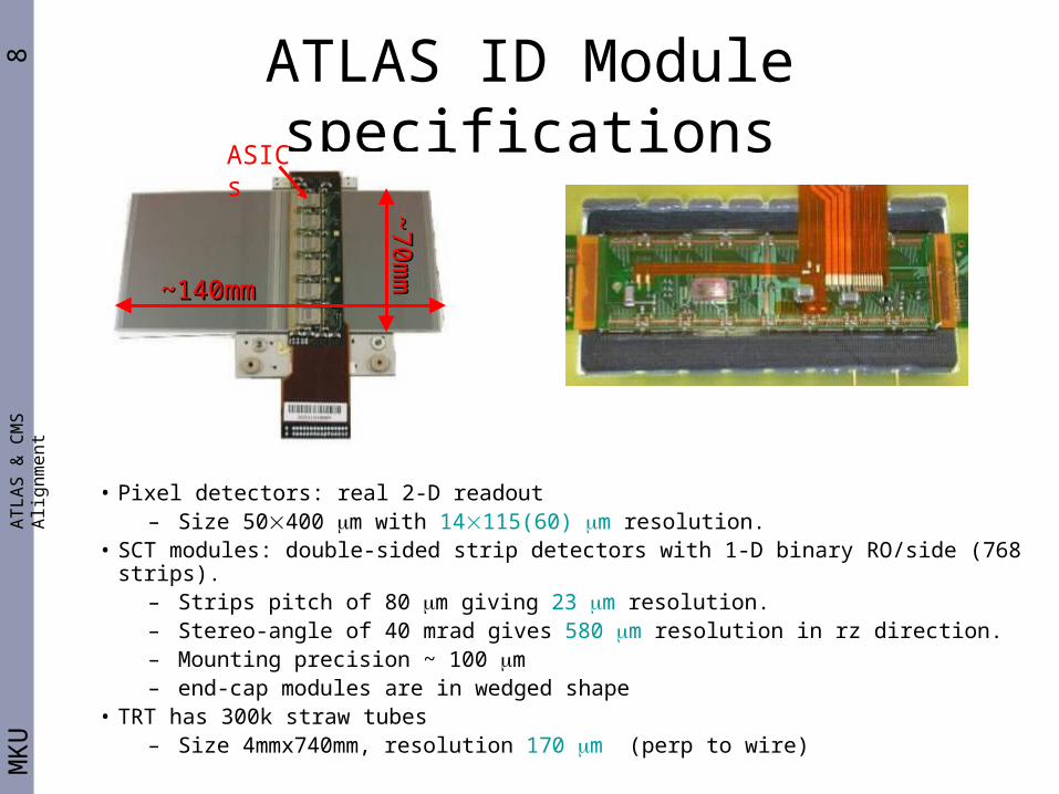
8M
KU
AT
LA
S &
CM
S A
lign
me
nt
ATLAS ID Module specifications
~140mm~140mm
~70m
m~
70mm
ASICs
• Pixel detectors: real 2-D readout – Size 50400 m with 14115(60) m resolution.
• SCT modules: double-sided strip detectors with 1-D binary RO/side (768 strips).– Strips pitch of 80 m giving 23 m resolution. – Stereo-angle of 40 mrad gives 580 m resolution in rz direction.– Mounting precision ~ 100 m – end-cap modules are in wedged shape
• TRT has 300k straw tubes– Size 4mmx740mm, resolution 170 m (perp to wire)
9M
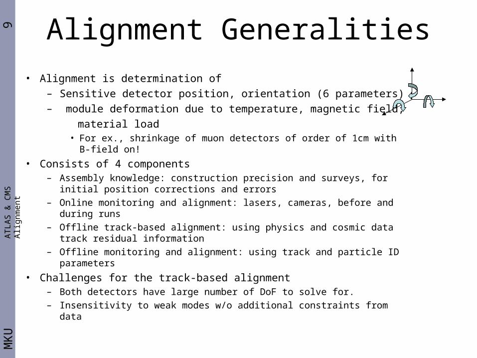
KU
Alignment GeneralitiesA
TL
AS
& C
MS
Alig
nm
en
t
• Alignment is determination of
– Sensitive detector position, orientation (6 parameters)
– module deformation due to temperature, magnetic field,
material load• For ex., shrinkage of muon detectors of order of 1cm with B-field on!
• Consists of 4 components– Assembly knowledge: construction precision and surveys, for initial
position corrections and errors– Online monitoring and alignment: lasers, cameras, before and during
runs– Offline track-based alignment: using physics and cosmic data track
residual information– Offline monitoring and alignment: using track and particle ID parameters
• Challenges for the track-based alignment– Both detectors have large number of DoF to solve for.– Insensitivity to weak modes w/o additional constraints from data

10M
KU
Prospects for LHC BeamsA
TL
AS
& C
MS
Alig
nm
en
t
With the recent magnet problems, not sure will
happen in time or happen at all…
Parasitic collisions with wide range of interaction z-point
11M
KU
Expected Event RatesA
TL
AS
& C
MS
Alig
nm
en
t
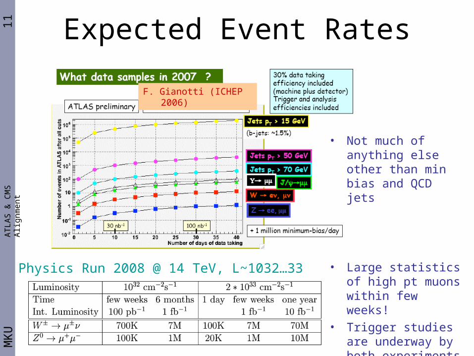
F. Gianotti (ICHEP 2006)
Physics Run 2008 @ 14 TeV, L~1032…33 • Large statistics of high pt muons within few weeks!
• Trigger studies are underway by both experiments
• Not much of anything else other than min bias and QCD jets
12M
KU
Who Ordered Misalignment?A
TL
AS
& C
MS
Alig
nm
en
t
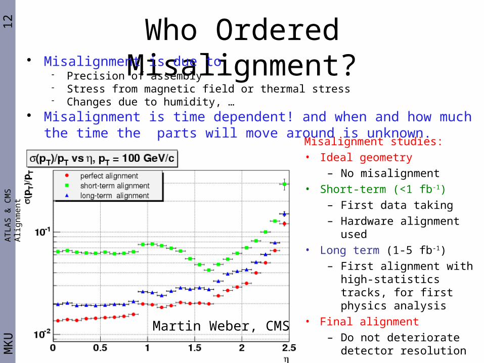
Misalignment studies:
• Ideal geometry
– No misalignment
• Short-term (<1 fb-1)
– First data taking
– Hardware alignment used
• Long term (1-5 fb-1)
– First alignment with high-statistics tracks, for first physics analysis
• Final alignment
– Do not deteriorate detector resolution
Misalignment is due to Precision of assembly Stress from magnetic field or thermal stress Changes due to humidity, …
Misalignment is time dependent! and when and how much the time the parts will move around is unknown.
Martin Weber, CMS
13M
KU
Misalignment: BSM SearchesA
TL
AS
& C
MS
Alig
nm
en
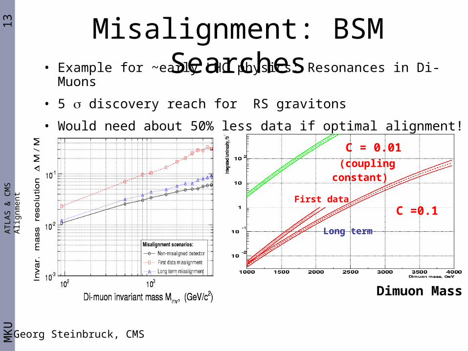
t C = 0.01 (coupling constant)
C =0.1First data
Long term
Dimuon Mass
• Example for ~early LHC physics: Resonances in Di-Muons
• 5 discovery reach for RS gravitons
• Would need about 50% less data if optimal alignment!
Georg Steinbruck, CMS
14M
KU
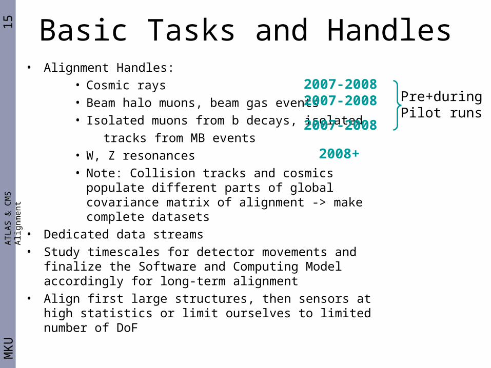
Basic Tasks and HandlesA
TL
AS
& C
MS
Alig
nm
en
t
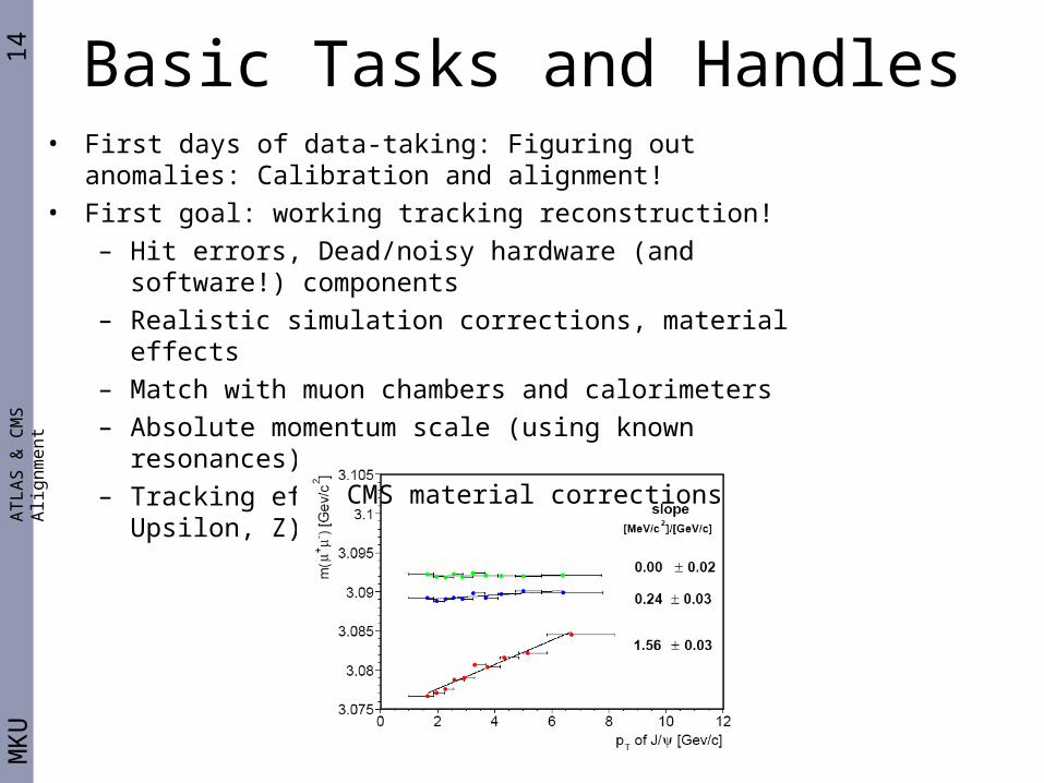
• First days of data-taking: Figuring out anomalies: Calibration and alignment!
• First goal: working tracking reconstruction!
– Hit errors, Dead/noisy hardware (and software!) components
– Realistic simulation corrections, material effects
– Match with muon chambers and calorimeters
– Absolute momentum scale (using known resonances)
– Tracking efficiency (dimuons from J/, Upsilon, Z)
CMS material corrections
15M
KU
Basic Tasks and HandlesA
TL
AS
& C
MS
Alig
nm
en
t
• Alignment Handles:
• Cosmic rays
• Beam halo muons, beam gas events
• Isolated muons from b decays, isolated
tracks from MB events
• W, Z resonances
• Note: Collision tracks and cosmics populate different parts of global covariance matrix of alignment -> make complete datasets
• Dedicated data streams
• Study timescales for detector movements and finalize the Software and Computing Model accordingly for long-term alignment
• Align first large structures, then sensors at high statistics or limit ourselves to limited number of DoF
2007-20082007-2008
2007-2008
2008+
Pre+during Pilot runs
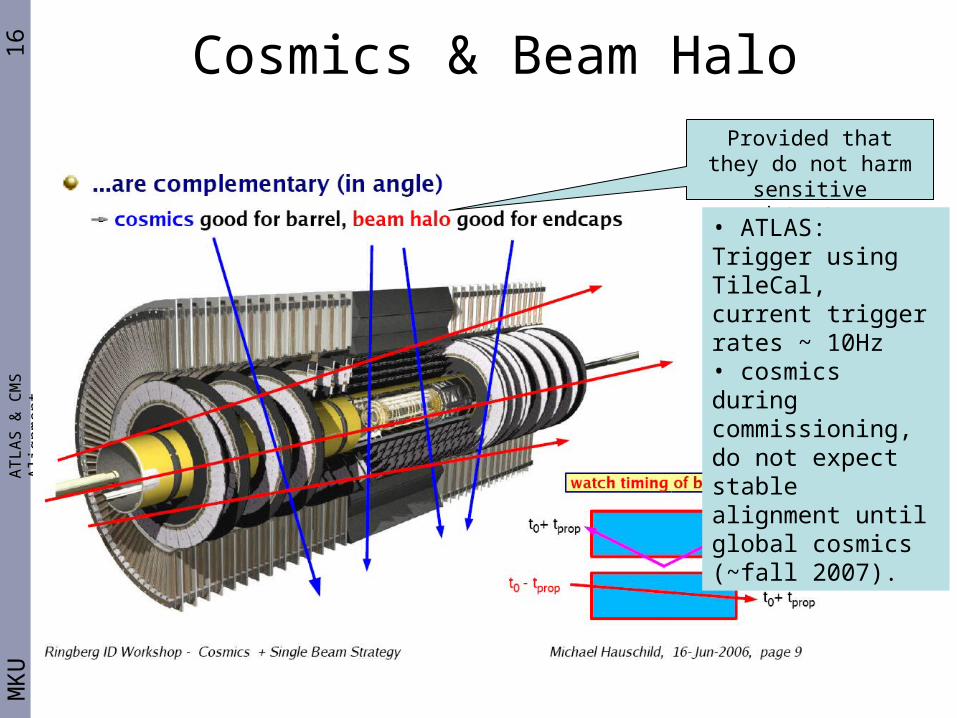
16M
KU
Cosmics & Beam HaloA
TL
AS
& C
MS
Alig
nm
en
t
Provided that they do not harm sensitive detector material!
• ATLAS: Trigger using TileCal, current trigger rates ~ 10Hz• cosmics during commissioning, do not expect stable alignment until global cosmics (~fall 2007).
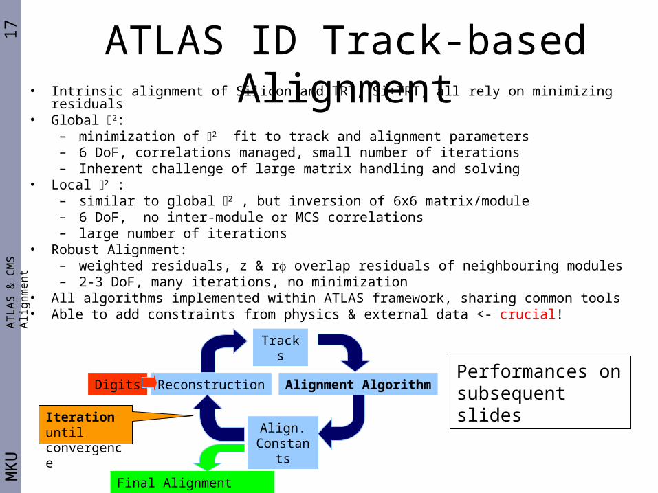
17M
KU
AT
LA
S &
CM
S A
lign
me
nt
ATLAS ID Track-based Alignment• Intrinsic alignment of Silicon and TRT, Si+TRT, all rely on minimizing residuals• Global 2:
– minimization of 2 fit to track and alignment parameters– 6 DoF, correlations managed, small number of iterations– Inherent challenge of large matrix handling and solving
• Local 2 : – similar to global 2 , but inversion of 6x6 matrix/module– 6 DoF, no inter-module or MCS correlations – large number of iterations
• Robust Alignment: – weighted residuals, z & r overlap residuals of neighbouring modules– 2-3 DoF, many iterations, no minimization
• All algorithms implemented within ATLAS framework, sharing common tools• Able to add constraints from physics & external data <- crucial!
Digits Reconstruction Alignment Algorithm
Align.Constant
s
Tracks
Final Alignment Constants
Iteration until convergence
Performances on subsequent slides
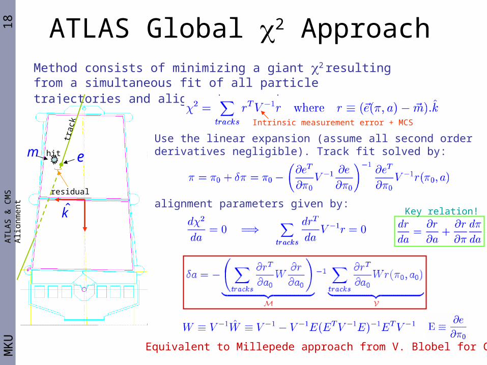
18M
KU
AT
LA
S &
CM
S A
lign
me
nt
Method consists of minimizing a giant 2 resulting from a simultaneous fit of all particle trajectories and alignment parameters:
Use the linear expansion (assume all second order derivatives negligible). Track fit solved by:
alignment parameters given by:Key relation!
Intrinsic measurement error + MCS
trac
k
hit
residual
k̂
em
Equivalent to Millepede approach from V. Blobel for CMS
ATLAS Global 2 Approach
19M
KU
CMS Track-based ID AlignmentA
TL
AS
& C
MS
Alig
nm
en
t
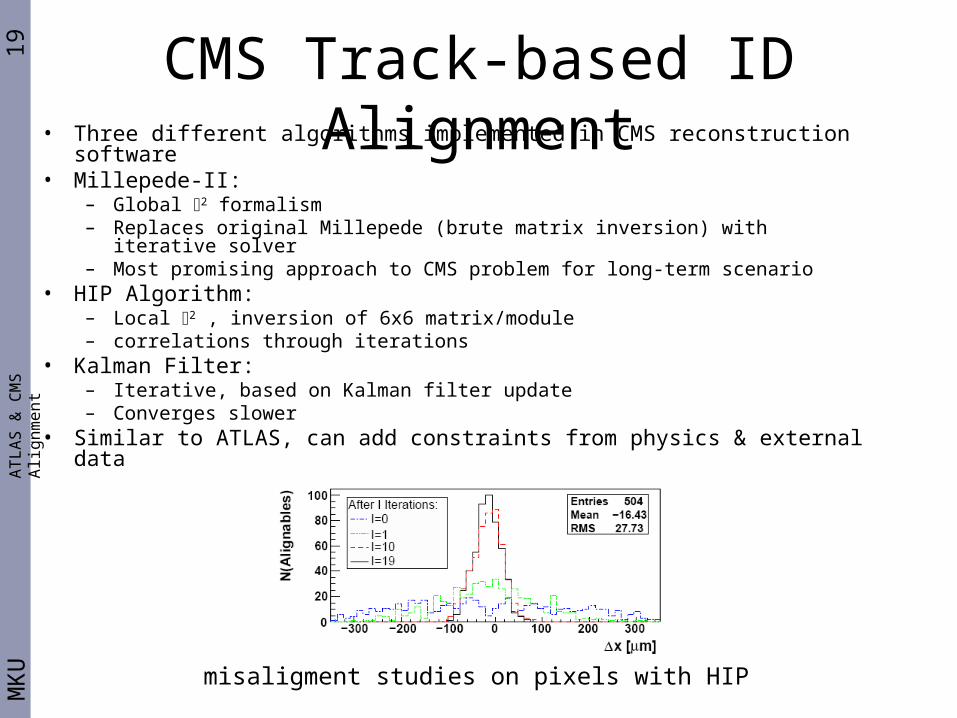
• Three different algorithms implemented in CMS reconstruction software • Millepede-II:
– Global 2 formalism– Replaces original Millepede (brute matrix inversion) with iterative solver– Most promising approach to CMS problem for long-term scenario
• HIP Algorithm: – Local 2 , inversion of 6x6 matrix/module– correlations through iterations
• Kalman Filter: – Iterative, based on Kalman filter update– Converges slower
• Similar to ATLAS, can add constraints from physics & external data
misaligment studies on pixels with HIP
20M
KU
Solving Large Degrees of FreedomA
TL
AS
& C
MS
Alig
nm
en
t
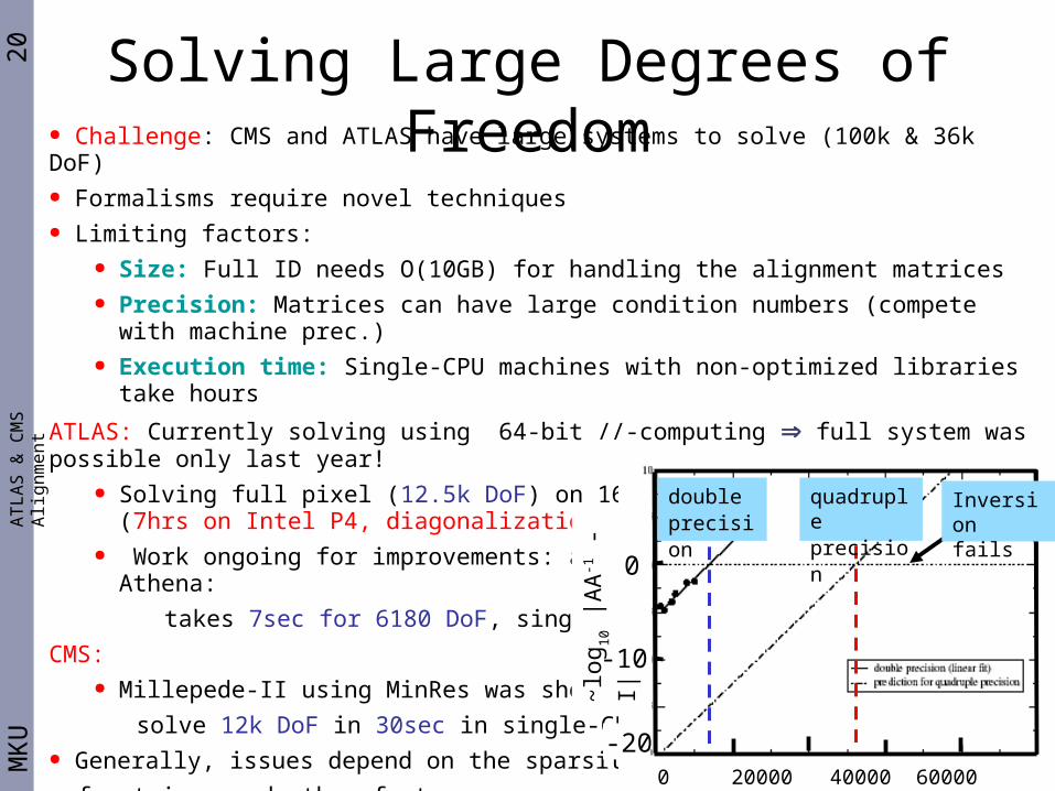
● Challenge: CMS and ATLAS have large systems to solve (100k & 36k DoF)● Formalisms require novel techniques● Limiting factors:
● Size: Full ID needs O(10GB) for handling the alignment matrices ● Precision: Matrices can have large condition numbers (compete with machine prec.)● Execution time: Single-CPU machines with non-optimized libraries take hours
ATLAS: Currently solving using 64-bit //-computing ⇒ full system was possible only last year!● Solving full pixel (12.5k DoF) on 16 nodes takes only 10mins (7hrs on Intel P4,
diagonalization)● Work ongoing for improvements: already implemented MA27 in Athena:
takes 7sec for 6180 DoF, single-CPU
CMS:● Millepede-II using MinRes was shown to
solve 12k DoF in 30sec in single-CPU!● Generally, issues depend on the sparsity
of matrices and other factors.
Things get really complicated!
(During datataking, a few mins performance differences
in solvers may not be our bottleneck problem!) 0 20000 40000 60000 80000 N
doubleprecision
quadrupleprecision
~lo
g 10 |A
A-1 -
I|
Inversion fails
0
-10
-20
21M
KU
“Weak” Distortional Modes..A
TL
AS
& C
MS
Alig
nm
en
t
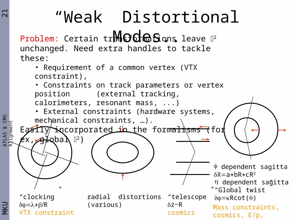
“clocking”RVTX constraint
“telescope”z~Rcosmics
radial distortions(various)
dependent sagittaXabRcR2
dependent sagitta“Global twist”Rcot()
Problem: Certain transformations leave 2 unchanged. Need extra handles to tackle these:
• Requirement of a common vertex (VTX constraint),• Constraints on track parameters or vertex position (external tracking, calorimeters, resonant mass, ...)• External constraints (hardware systems, mechanical constraints, …).
Easily incorporated in the formalisms (for ex, global 2)
Mass constraints, cosmics, E/p, charge dep

22M
KU
More on Weak Global ModesA
TL
AS
& C
MS
Alig
nm
en
t
Example “lowest modes” in PIX+SCT Global Freedom ignored
Weak modes contribute to the lowest part of the eigenspectrum. These deformations lead directly to biases on physics (systematic effects). Such global effects already under study (lots of preliminary results, have no time to show all, so will sample in next pages!)
23M
KU
ATLAS “CSC” ChallengeA
TL
AS
& C
MS
Alig
nm
en
t
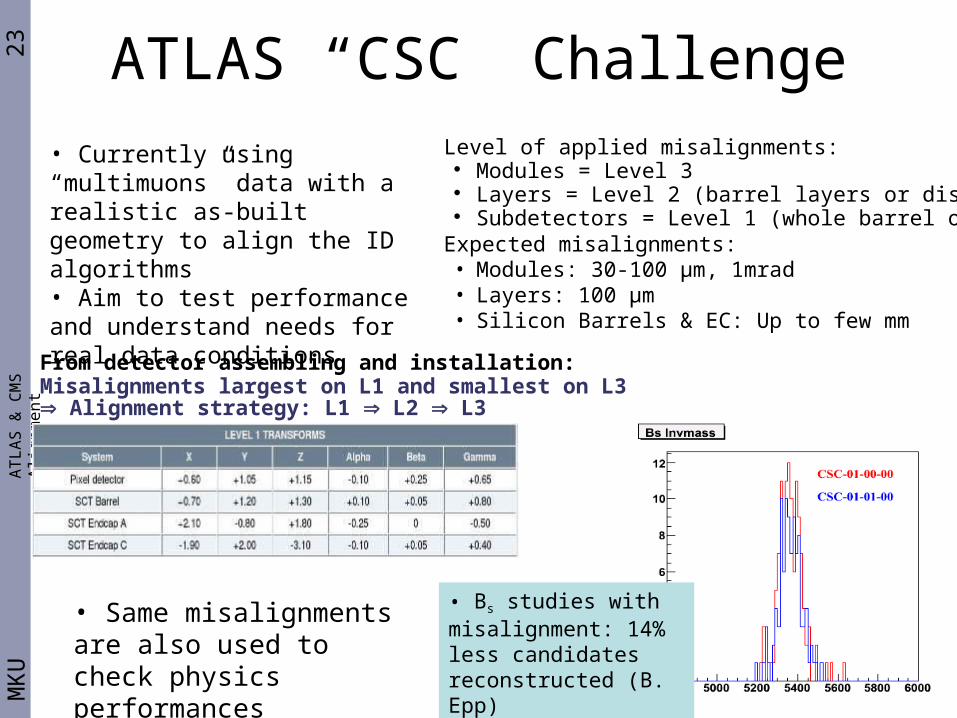
Level of applied misalignments: Modules = Level 3 Layers = Level 2 (barrel layers or disks) Subdetectors = Level 1 (whole barrel or EC)
Expected misalignments:• Modules: 30-100 µm, 1mrad• Layers: 100 µm• Silicon Barrels & EC: Up to few mm
From detector assembling and installation:Misalignments largest on L1 and smallest on L3⇒ Alignment strategy: L1 ⇒ L2 ⇒ L3
• Currently using “multimuons” data with a realistic as-built geometry to align the ID algorithms• Aim to test performance and understand needs for real data conditions
• Bs studies with misalignment: 14% less candidates reconstructed (B. Epp)
• Same misalignments are also used to check physics performances
24M
KU
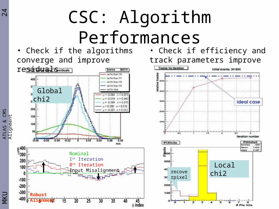
CSC: Algorithm PerformancesA
TL
AS
& C
MS
Alig
nm
en
t
Global chi2
• Check if the algorithms converge and improve residuals
recoverpixel
• Check if efficiency and track parameters improve
Local chi2
Nominal1st Iteration8th IterationInput Misalignment
Robust Alignment
25M
KU
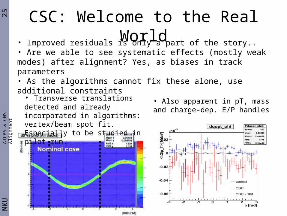
CSC: Welcome to the Real WorldA
TL
AS
& C
MS
Alig
nm
en
t
• Improved residuals is only a part of the story..• Are we able to see systematic effects (mostly weak modes) after alignment? Yes, as biases in track parameters• As the algorithms cannot fix these alone, use additional constraints
• Transverse translations detected and already incorporated in algorithms: vertex/beam spot fit. Especially to be studied in pilot run.
• Also apparent in pT, mass and charge-dep. E/P handles
26M
KU
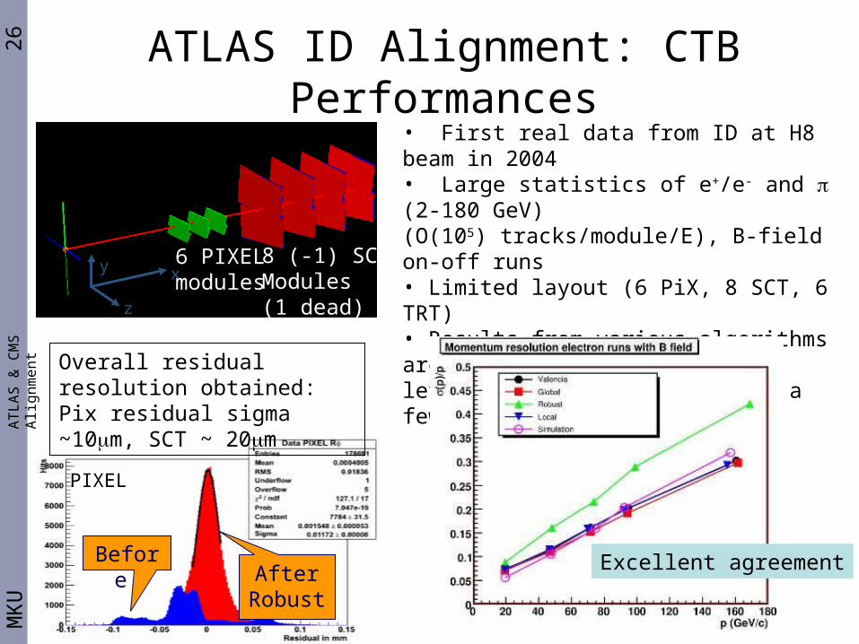
ATLAS ID Alignment: CTB PerformancesA
TL
AS
& C
MS
Alig
nm
en
t
• First real data from ID at H8 beam in 2004• Large statistics of e+/e- and (2-180 GeV)(O(105) tracks/module/E), B-field on-off runs• Limited layout (6 PiX, 8 SCT, 6 TRT) • Results from various algorithms are being combined: reached a level sensitive to effects at a few microns!
Before After
Robust
PIXEL
Overall residual resolution obtained: Pix residual sigma ~10m, SCT ~ 20m
z
y x6 PIXELmodules
8 (-1) SCTModules(1 dead)
Excellent agreement
27M
KU
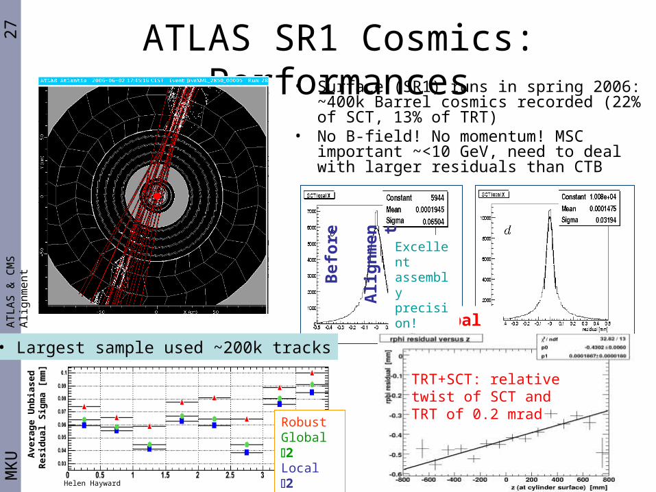
ATLAS SR1 Cosmics: PerformancesA
TL
AS
& C
MS
Alig
nm
en
t
Global 2
Bef
ore
Ali
gn
men
t
RobustGlobal 2Local 2
Helen Hayward
Ave
rag
e U
nb
iase
d
Res
idu
al S
igm
a [m
m]
• Surface (SR1) runs in spring 2006: ~400k Barrel cosmics recorded (22% of SCT, 13% of TRT)
• No B-field! No momentum! MSC important ~<10 GeV, need to deal with larger residuals than CTB
Excellent assembly precision!
TRT+SCT: relative twist of SCT and TRT of 0.2 mrad
• Largest sample used ~200k tracks
28M
KU
ATLAS ID optical alignment (FSI)A
TL
AS
& C
MS
Alig
nm
en
t
Barrel SCT
End-cap SCT 165x2=33080+(3x[80+16])+(2x72)=512
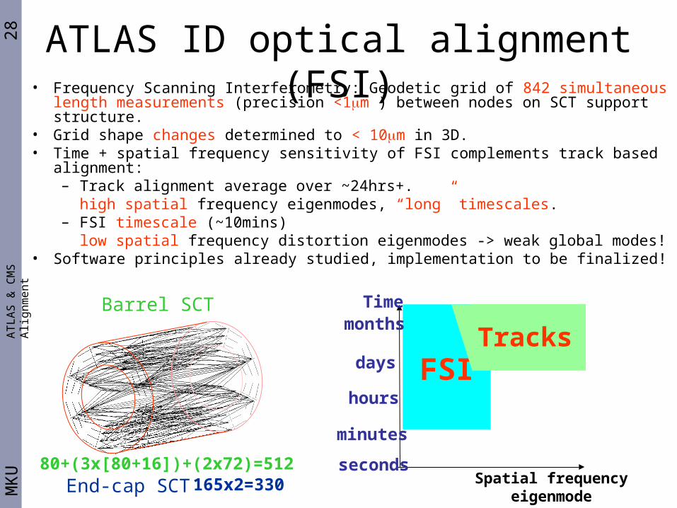
• Frequency Scanning Interferometry: Geodetic grid of 842 simultaneous length measurements (precision <1m ) between nodes on SCT support structure.
• Grid shape changes determined to < 10m in 3D.• Time + spatial frequency sensitivity of FSI complements track based alignment:
– Track alignment average over ~24hrs+. high spatial frequency eigenmodes, “long” timescales.
– FSI timescale (~10mins) low spatial frequency distortion eigenmodes -> weak global modes!
• Software principles already studied, implementation to be finalized!
Spatial frequencyeigenmode
FSI
Time
seconds
minutes
hours
days
monthsTracks
29M
KU
ATLAS FSI on detectorA
TL
AS
& C
MS
Alig
nm
en
t
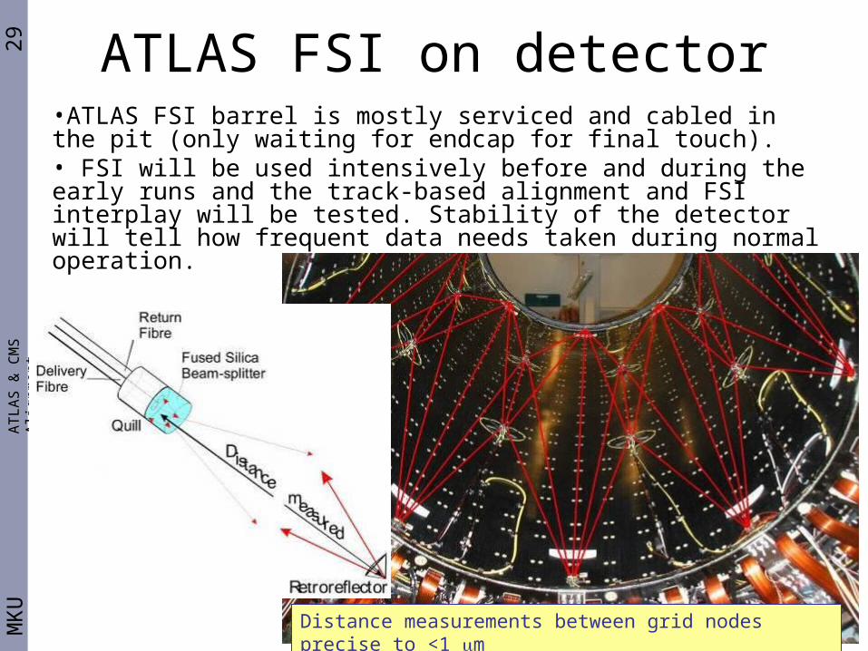
Distance measurements between grid nodes precise to <1 m
•ATLAS FSI barrel is mostly serviced and cabled in the pit (only waiting for endcap for final touch).• FSI will be used intensively before and during the early runs and the track-based alignment and FSI interplay will be tested. Stability of the detector will tell how frequent data needs taken during normal operation.
30M
KU
ATLAS -spectrometer Alignment• Spectrometer: 1252 MDT chambers
(708 Barrel, 544 Endcap)
Muon track will be measured with 3 drift tube chambers (~18-20 layers)
Requirement:10% pT resolution on 1TeV muon:
sagitta of 500 μm measured with 50 μm accuracy
muon chambers must be aligned to 30 μm (Intrinsic resolution of a channel: 80 μm)
When Toroid is on, chambers will move by several mm => Optical alignment needed.hourly geometry changes expected.
AT
LA
S &
CM
S A
lign
me
nt
MDTs monitored for 9 chamber distortions, eg, elongation, sagging,.. 3 system with 3-point principle
CCD
Spot target
Lens
91mm53 mm
BCam
Florian Bauer, 4/9/2006, LHC Alignment Workshop
31M
KU
ATLAS alignment Status• Optical alignment software validated at CTB, hardware installation underway.• 2 softwares: ASAP (barrel) and AraMyS (endcap)
• Combine optical information with straight/High Pt tracks in global fit• Describe the 9 chamber deformations in the fit => 6 + 9 DoFs per chamber.• Handle up to 10k DoFs both in the Barrel and Endcap
• Run online with a latency of 24h. => robust algorithms, automated dataflow, monitoring, use of Databases as IO• For alignment&calibration, a special L2 trigger data stream is being setup• Misalignment studies show that the algorithms see the misalignments• Obtaining the required alignment is shown to take about 1/2 day, assuming parallel inner/outer chambers (ATLAS T&P week).
AT
LA
S &
CM
S A
lign
me
nt
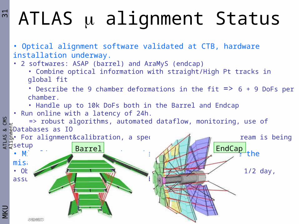
EndCapBarrel
32M
KU
CMS Hardware Alignment SystemA
TL
AS
& C
MS
Alig
nm
en
t
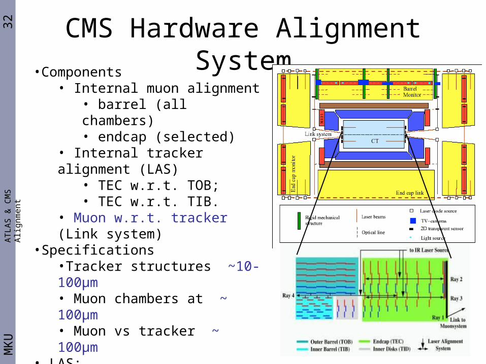
•Components• Internal muon alignment
• barrel (all chambers)• endcap (selected)
• Internal tracker alignment (LAS)• TEC w.r.t. TOB;• TEC w.r.t. TIB.
• Muon w.r.t. tracker (Link system)•Specifications
•Tracker structures ~10-100μm• Muon chambers at ~ 100μm• Muon vs tracker ~ 100μm
• LAS:• monitor selected modules to get global alignment• 16+10+12 beams in total• Beams treated like tracks
33M
KU
CMS Hardware Alignment SystemA
TL
AS
& C
MS
Alig
nm
en
t
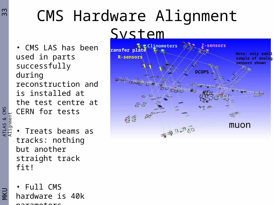
R-sensors
Z-sensors
Note: only smallsample of analog sensors shown
ClinometersTransfer plate
DCOPS
• CMS LAS has been used in parts successfully during reconstruction and is installed at the test centre at CERN for tests
• Treats beams as tracks: nothing but another straight track fit!
• Full CMS hardware is 40k parameters
• Lots of software challenges, similar to track-based algorithms
muon
34M
KU
Surveying the DetectorsA
TL
AS
& C
MS
Alig
nm
en
t
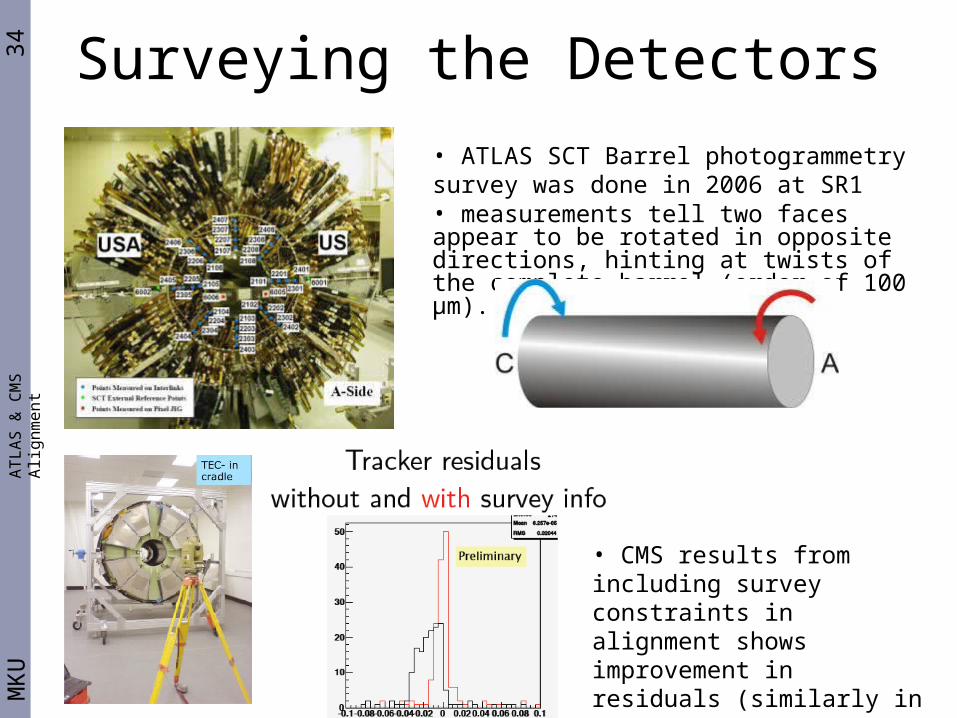
• ATLAS SCT Barrel photogrammetry survey was done in 2006 at SR1• measurements tell two faces appear to be rotated in opposite directions, hinting at twists of the complete barrel (order of 100 μm).
• CMS results from including survey constraints in alignment shows improvement in residuals (similarly in ATLAS)
35M
KU
ATLAS & CMS Tracker StatusA
TL
AS
& C
MS
Alig
nm
en
t
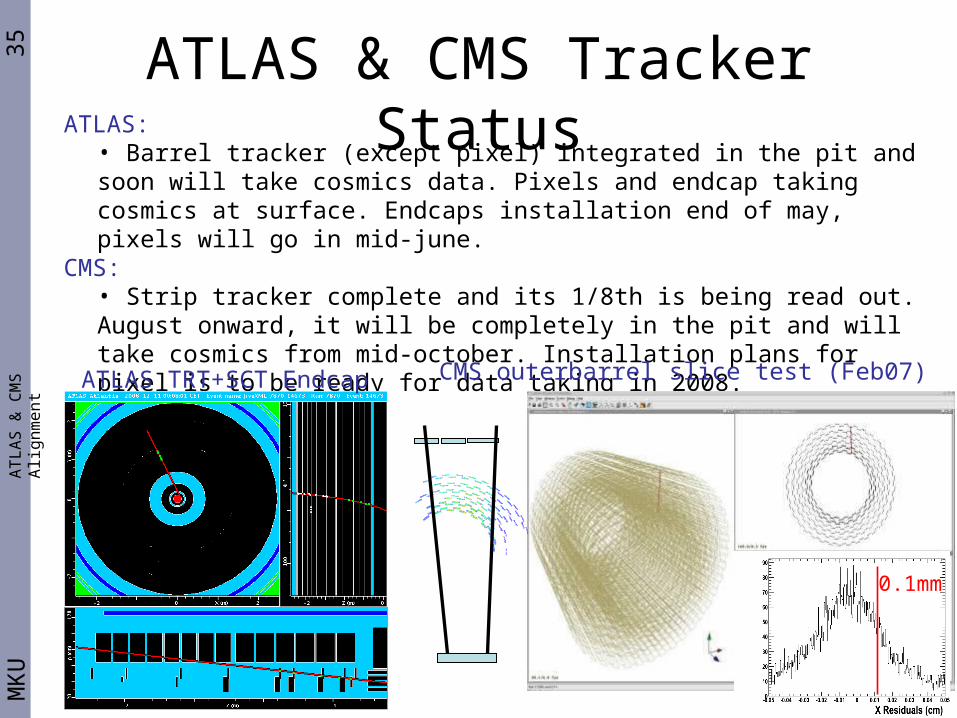
ATLAS: • Barrel tracker (except pixel) integrated in the pit and soon will take cosmics data. Pixels and endcap taking cosmics at surface. Endcaps installation end of may, pixels will go in mid-june.
CMS: • Strip tracker complete and its 1/8th is being read out. August onward, it will be completely in the pit and will take cosmics from mid-october. Installation plans for pixel is to be ready for data taking in 2008.
ATLAS TRT+SCT Endcap CMS outerbarrel slice test (Feb07)
0.1mm

36M
KU
Conclusions• Both experiments have similar challenges and ideas for alignment, with different choice
of optical alignment systems. • Both experiments’ track-based alignment software are in place, heavily tested, and
providing proof of principles. They are at the cutting edge of today’s computing resources.
• We have been looking at real data already! Misaligned simulation studies underway.• A lot has been learned, fixed, improved, but there is a lot more to do!• We will be ready for collision data, however, full scalability needs to be proven with real
collision data conditions: datastream from triggers, huge data samples, computing power, GRID-readiness, etc.
• The first collisions will be useful to exercise further the tools and understand the actual needs (time-scales, online monitoring, ...) rather than providing the final set of constants.
• Thankfully we do not need to reinvent most of the wheel, previous colliders suffered from similar symptoms.
• We need to be prepared for the unexpected, many issues upstream and downstream of alignment algorithms will exist and need to be understood: we cannot expect to obtain final module level alignment from day 1, but will likely nail down the global structures quickly.
AT
LA
S &
CM
S A
lign
me
nt
Please Stay Tuned!
37M
KU
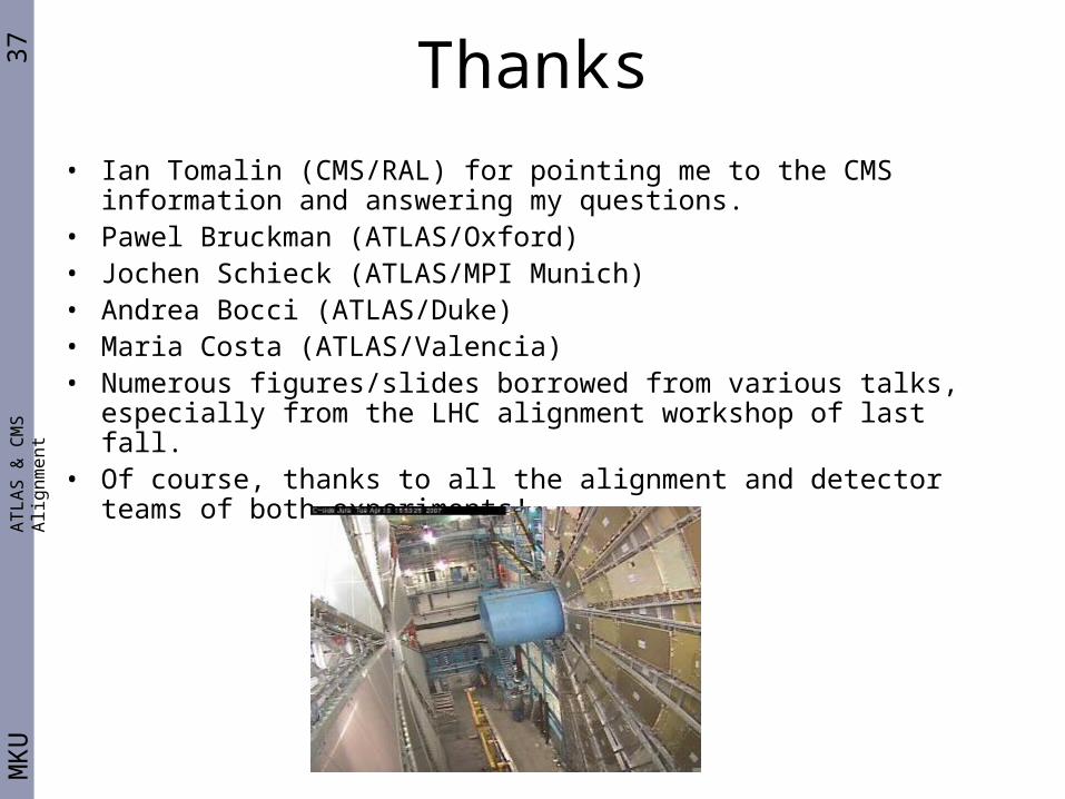
Thanks
• Ian Tomalin (CMS/RAL) for pointing me to the CMS information and answering my questions.
• Pawel Bruckman (ATLAS/Oxford)• Jochen Schieck (ATLAS/MPI Munich)• Andrea Bocci (ATLAS/Duke)• Maria Costa (ATLAS/Valencia)• Numerous figures/slides borrowed from various talks, especially from
the LHC alignment workshop of last fall.• Of course, thanks to all the alignment and detector teams of both
experiments!
AT
LA
S &
CM
S A
lign
me
nt
38M
KU
AT
LA
S &
CM
S A
lign
me
nt BACKUP
39M
KU
ATLAS scheduleA
TL
AS
& C
MS
Alig
nm
en
t
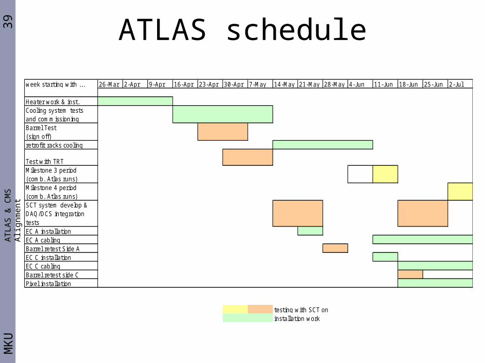
week starting with ... 26-Mar 2-Apr 9-Apr 16-Apr 23-Apr 30-Apr 7-May 14-May 21-May 28-May 4-J un 11-J un 18-J un 25-J un 2-J ul
Heater work & inst.Cooling system testsand commissioningBarrel Test(sign off)retrofit racks cooling
Test with TRTMilestone 3 period(comb. Atlas runs)Milestone 4 period(comb. Atlas runs)SCT system develop &DAQ/DCS integration testsEC A installationEC A cablingBarrel retest Side AEC C installationEC C cablingBarrel retest side CPixel installation
testing with SCT oninstallation work
40M
KU
ATLAS ID r viewA
TL
AS
& C
MS
Alig
nm
en
t
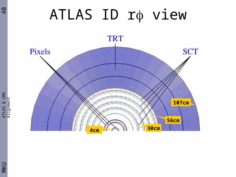
4cm 30cm
56cm
107cm
41M
KU
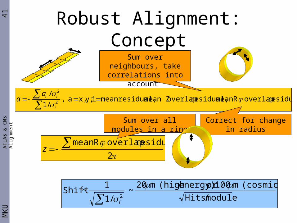
Robust Alignment: ConceptA
TL
AS
& C
MS
Alig
nm
en
t
residual overlap Rmean residual, overlap mean Z residual,mean i y;x, a ,/1
/2
2
i
iiaa
Sum over neighbours, take correlations into
account
Correct for change in radius
2
residual overlap Rmean z
Sum over all modules in a ring
module / Hits
(cosmics) m100or energy)(high m20~
/1
1 ~Shift
2
i
42M
KU
AT
LA
S &
CM
S A
lign
me
nt
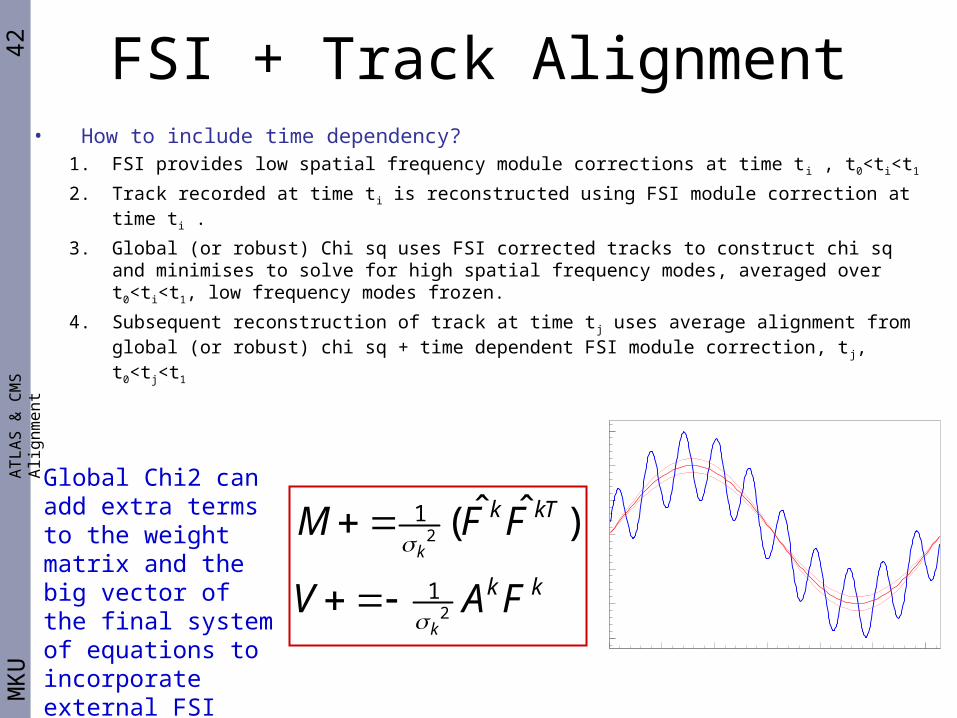
2
2
1
1
ˆ ˆ( )k
k
k kT
k k
M F F
V A F
Global Chi2 can add extra terms to the weight matrix and the big vector of the final system of equations to incorporate external FSI constraint
FSI + Track Alignment• How to include time dependency?
1. FSI provides low spatial frequency module corrections at time ti , t0<ti<t1
2. Track recorded at time ti is reconstructed using FSI module correction at time ti .
3. Global (or robust) Chi sq uses FSI corrected tracks to construct chi sq and minimises to solve for high spatial frequency modes, averaged over t0<ti<t1, low frequency modes frozen.
4. Subsequent reconstruction of track at time tj uses average alignment from global (or robust) chi sq + time dependent FSI module correction, t j, t0<tj<t1
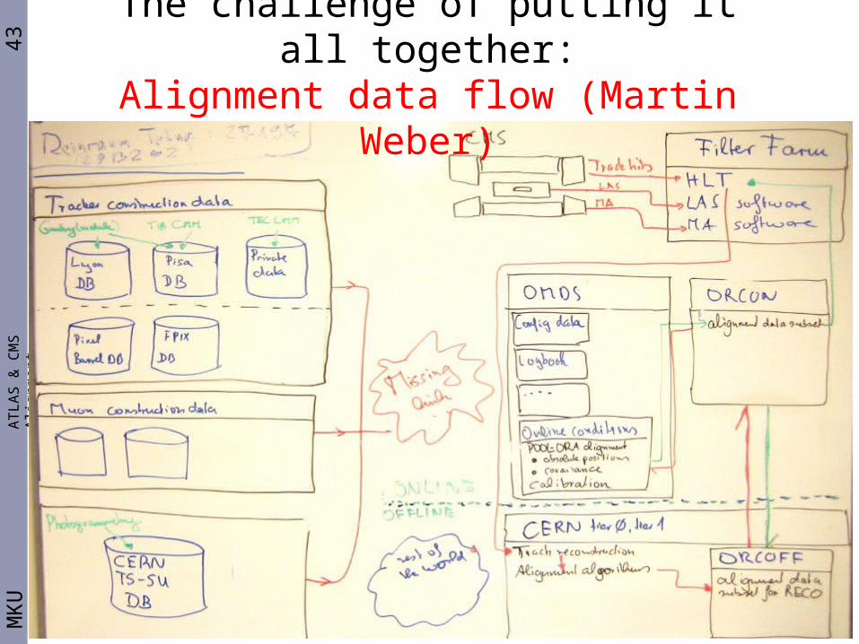
43M
KU
AT
LA
S &
CM
S A
lign
me
nt
The challenge of putting it all together:Alignment data flow (Martin Weber)