Embed Size (px)
Citation preview
2 of 18
DIALux The Basics
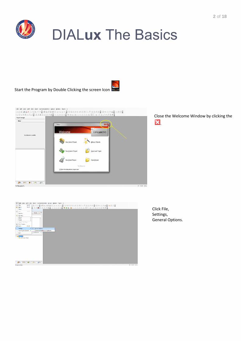
Start the Program by Double Clicking the screen Icon
Click File, Settings, General Options.
Close the Welcome Window by clicking the
.
3 of 18
DIALux The Basics
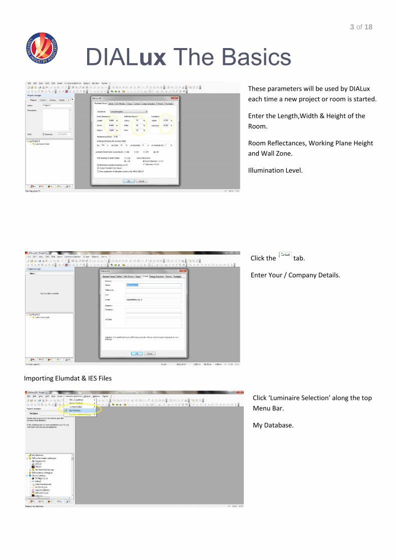
Importing Elumdat & IES Files
These parameters will be used by DIALux
each time a new project or room is started.
Enter the Length,Width & Height of the
Room.
Room Reflectances, Working Plane Height
and Wall Zone.
Illumination Level.
Click the tab.
Enter Your / Company Details.
Click ‘Luminaire Selection’ along the top
Menu Bar.
My Database.
4 of 18
DIALux The Basics
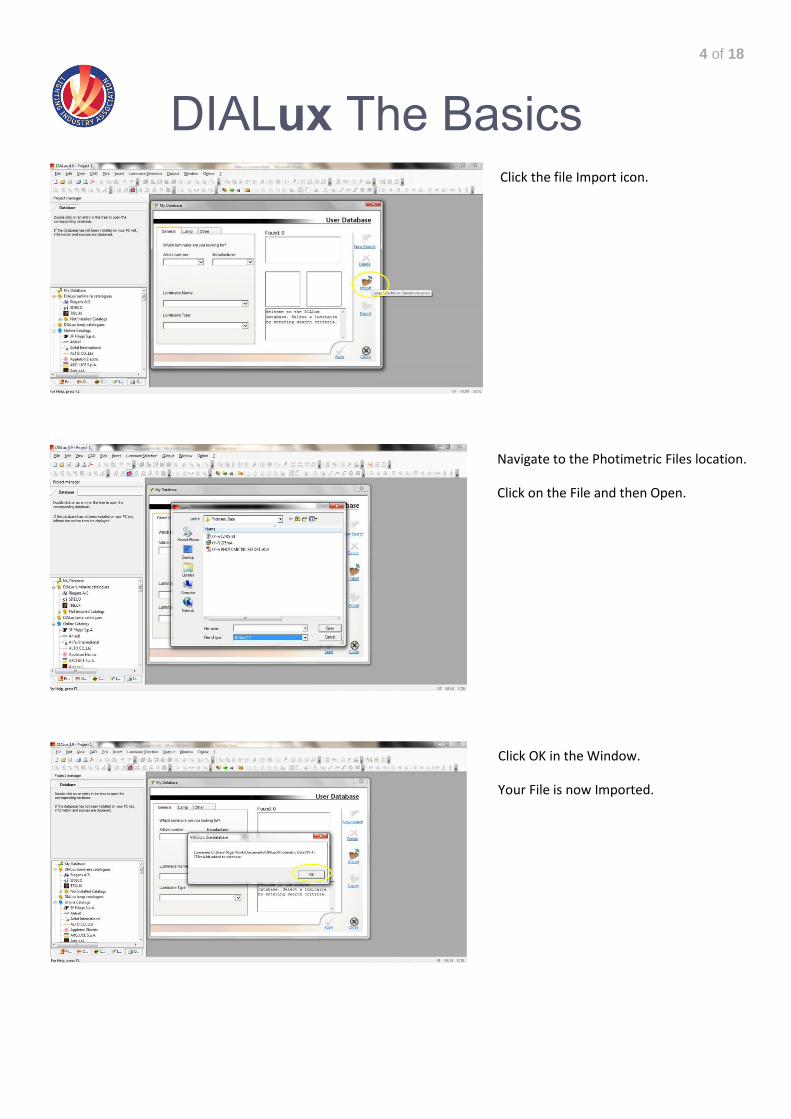
Click the file Import icon.
Navigate to the Photimetric Files location.
Click on the File and then Open.
Click OK in the Window.
Your File is now Imported.
5 of 18
DIALux The Basics
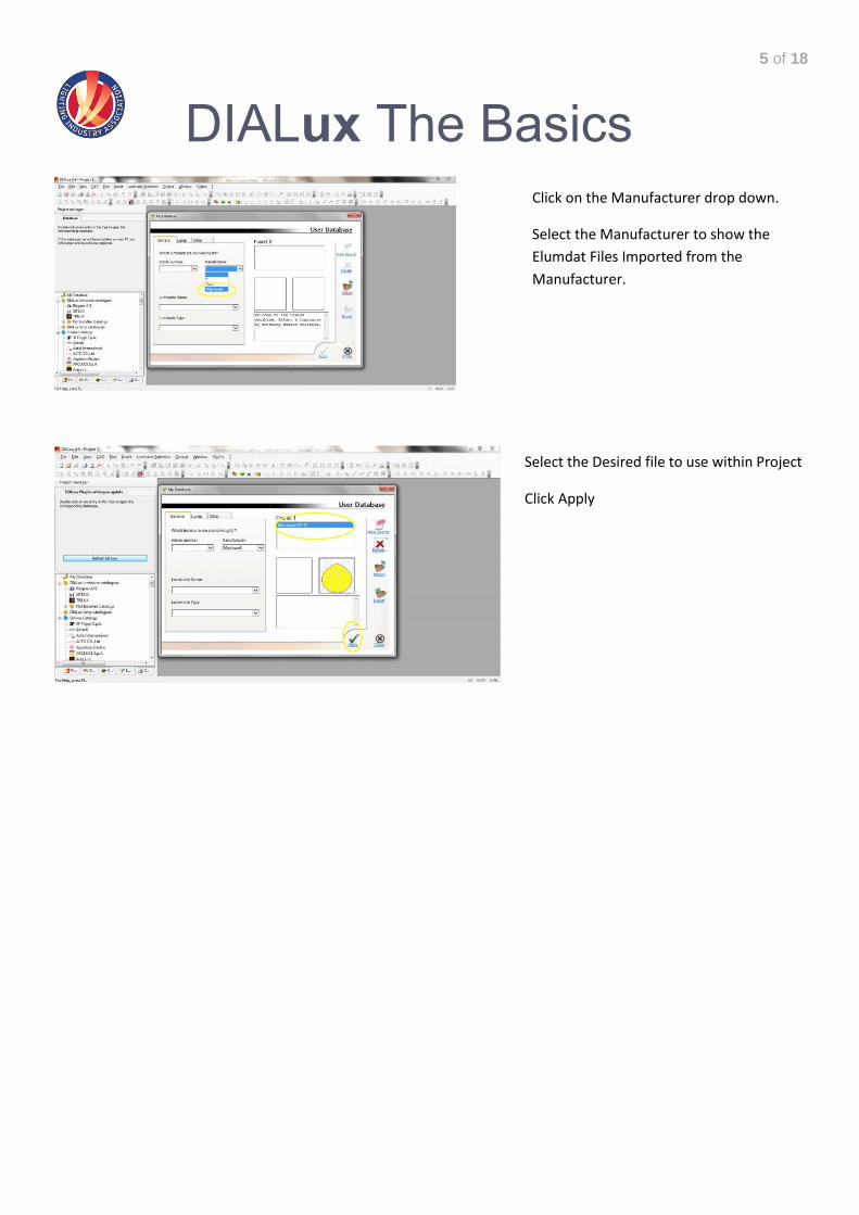
Click on the Manufacturer drop down.
Select the Manufacturer to show the
Elumdat Files Imported from the
Manufacturer.
Select the Desired file to use within Project
Click Apply
6 of 18
DIALux The Basics
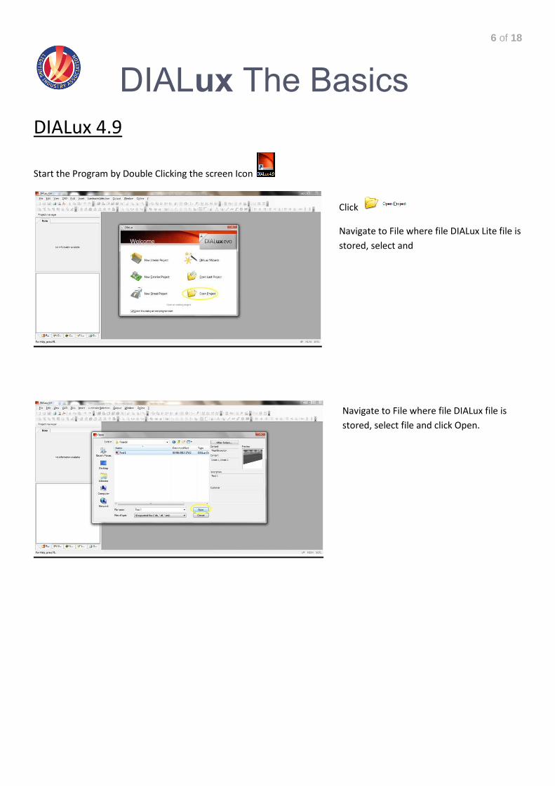
DIALux 4.9
Start the Program by Double Clicking the screen Icon
Click
Navigate to File where file DIALux Lite file is
stored, select and
Navigate to File where file DIALux file is
stored, select file and click Open.
7 of 18
DIALux The Basics
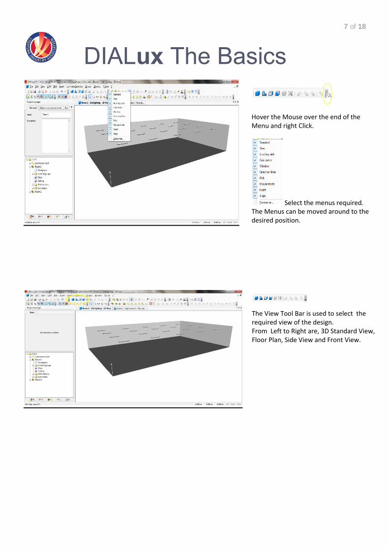
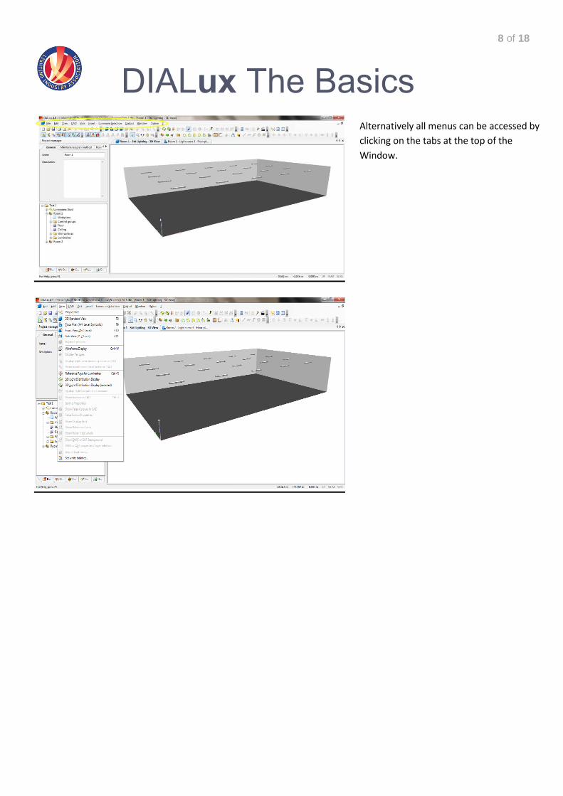
The View Tool Bar is used to select the required view of the design. From Left to Right are, 3D Standard View, Floor Plan, Side View and Front View.
Hover the Mouse over the end of the Menu and right Click.
Select the menus required. The Menus can be moved around to the desired position.
8 of 18
DIALux The Basics
Alternatively all menus can be accessed by
clicking on the tabs at the top of the
Window.
9 of 18
DIALux The Basics
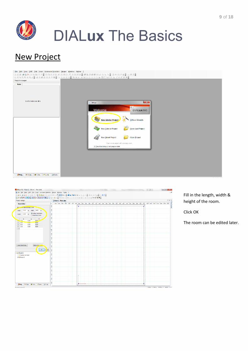
New Project
Fill in the length, width &
height of the room.
Click OK
The room can be edited later.
10 of 18
DIALux The Basics
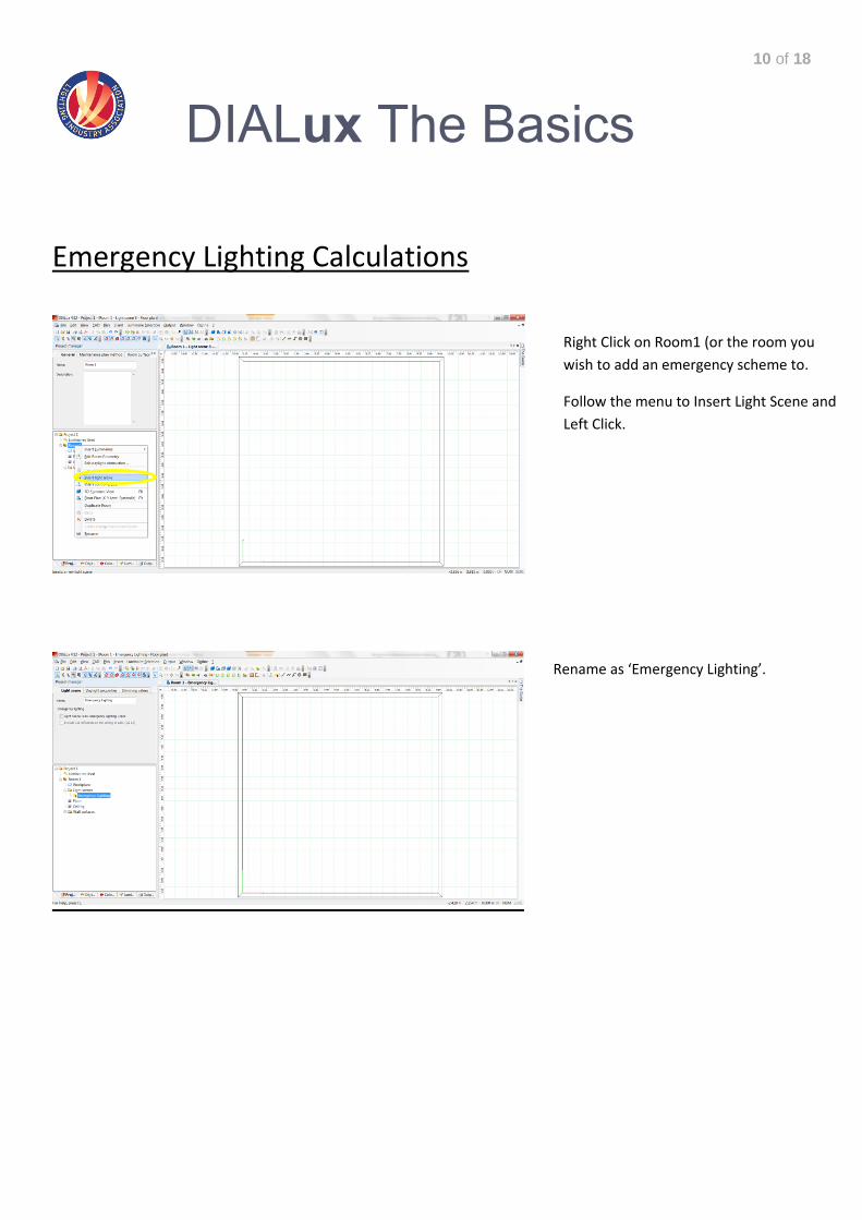
Emergency Lighting Calculations
Right Click on Room1 (or the room you
wish to add an emergency scheme to.
Follow the menu to Insert Light Scene and
Left Click.
Rename as ‘Emergency Lighting’.
11 of 18
DIALux The Basics
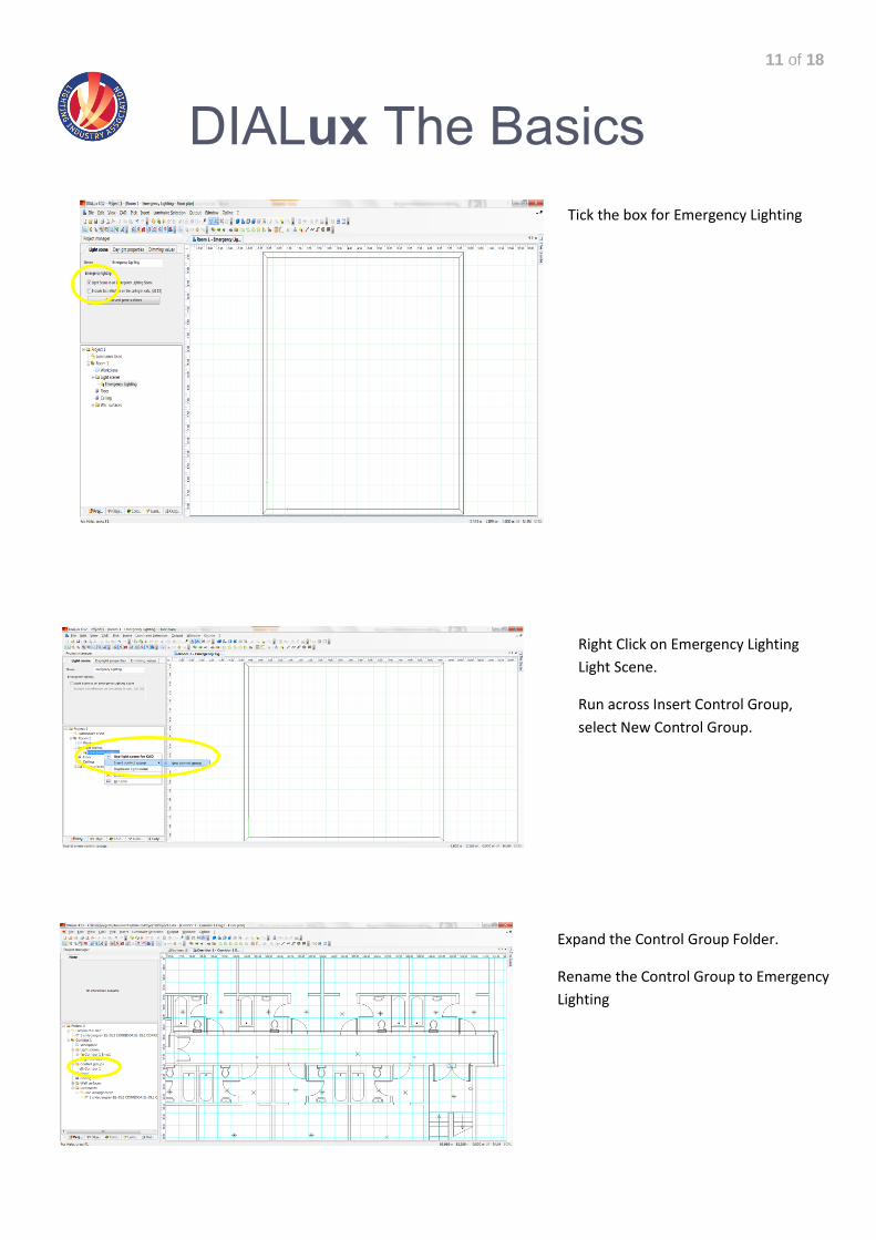
Right Click on Emergency Lighting
Light Scene.
Run across Insert Control Group,
select New Control Group.
Tick the box for Emergency Lighting
Expand the Control Group Folder.
Rename the Control Group to Emergency
Lighting
12 of 18
DIALux The Basics
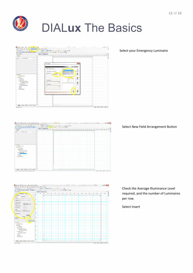
Select New Field Arrangement Button
Select your Emergency Luminaire
Check the Average Illuminance Level
required, and the number of Luminaires
per row.
Select Insert
13 of 18
DIALux The Basics
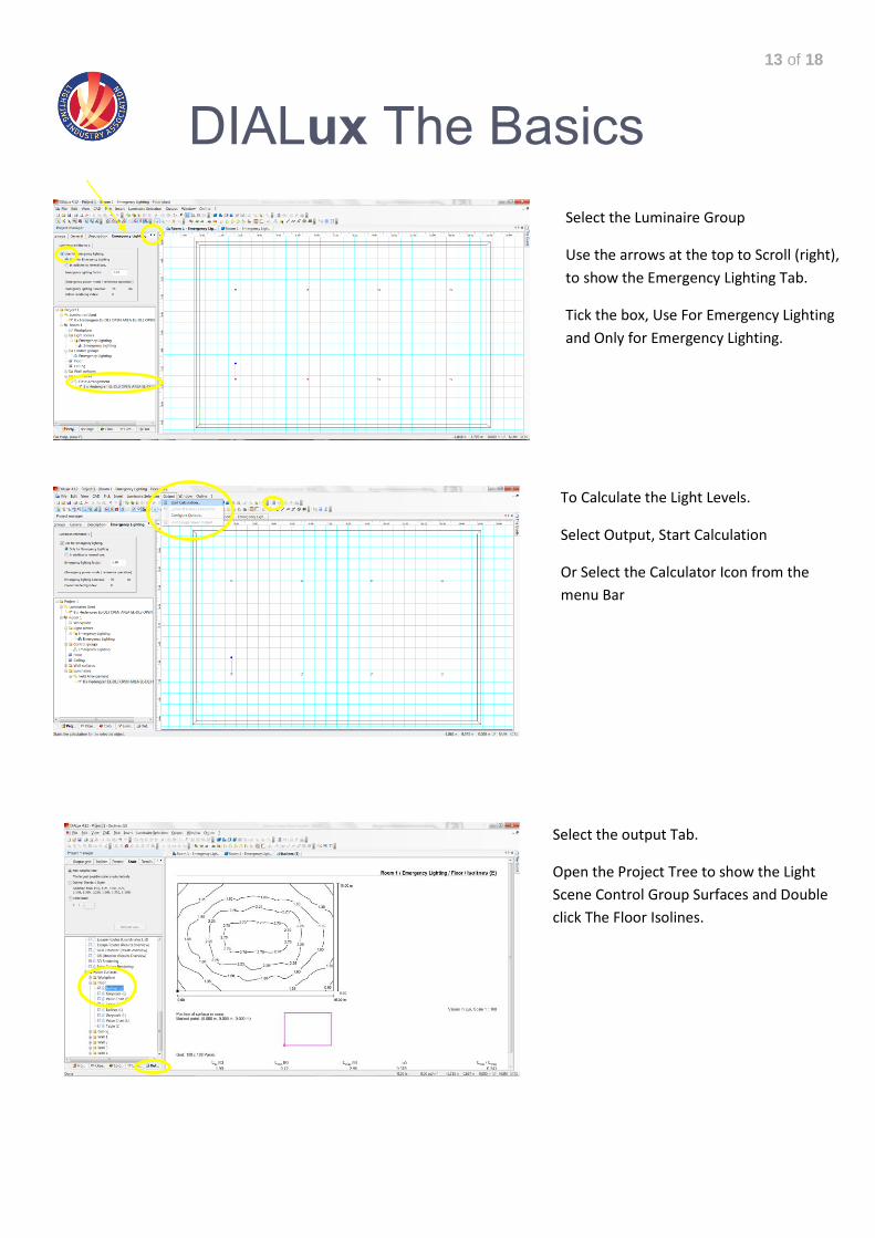
Select the Luminaire Group
Use the arrows at the top to Scroll (right),
to show the Emergency Lighting Tab.
Tick the box, Use For Emergency Lighting
and Only for Emergency Lighting.
To Calculate the Light Levels.
Select Output, Start Calculation
Or Select the Calculator Icon from the
menu Bar
Select the output Tab.
Open the Project Tree to show the Light
Scene Control Group Surfaces and Double
click The Floor Isolines.
14 of 18
DIALux The Basics
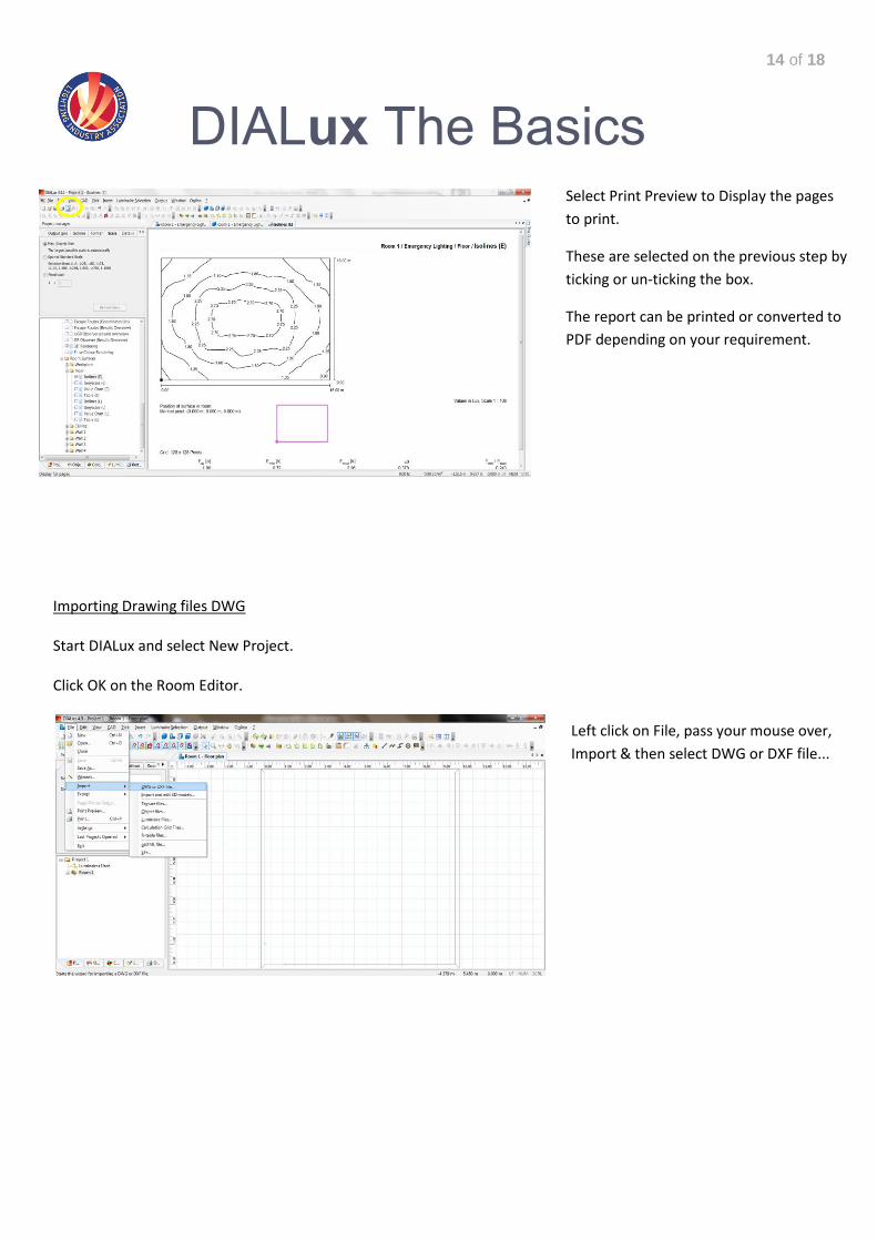
Importing Drawing files DWG Start DIALux and select New Project. Click OK on the Room Editor.
Left click on File, pass your mouse over,
Import & then select DWG or DXF file...
Select Print Preview to Display the pages
to print.
These are selected on the previous step by
ticking or un-ticking the box.
The report can be printed or converted to
PDF depending on your requirement.
15 of 18
DIALux The Basics
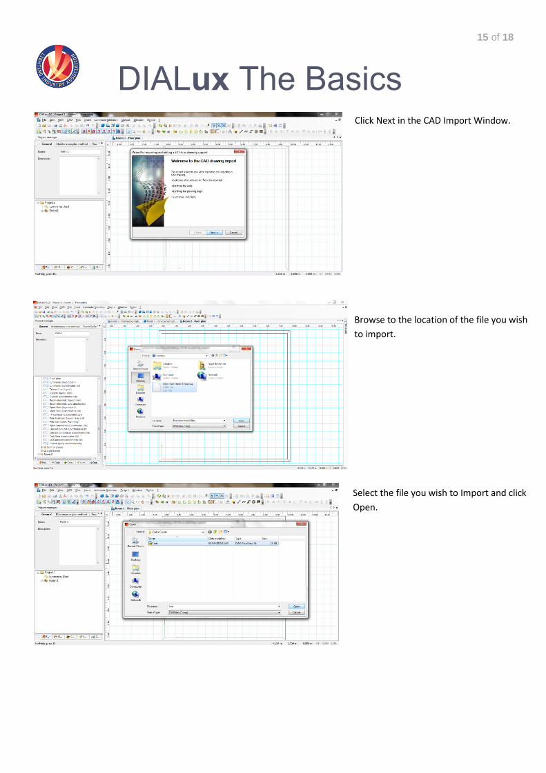
Click Next in the CAD Import Window.
Browse to the location of the file you wish
to import.
Select the file you wish to Import and click
Open.
16 of 18
DIALux The Basics
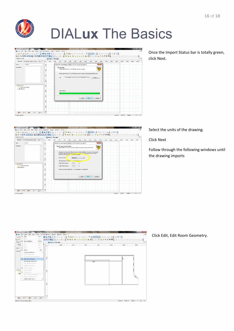
Once the Import Status bar is totally green,
click Next.
Select the units of the drawing.
Click Next
Follow through the following windows until
the drawing imports
Click Edit, Edit Room Geometry.
17 of 18
DIALux The Basics
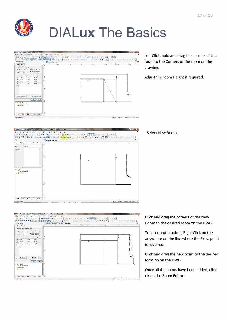
Left Click, hold and drag the corners of the
room to the Corners of the room on the
drawing.
Adjust the room Height if required.
Select New Room.
Click and drag the corners of the New
Room to the desired room on the DWG.
To insert extra points, Right Click on the
anywhere on the line where the Extra point
is required.
Click and drag the new point to the desired
location on the DWG.
Once all the points have been added, click
ok on the Room Editor.
18 of 18
DIALux The Basics