Embed Size (px)
Citation preview
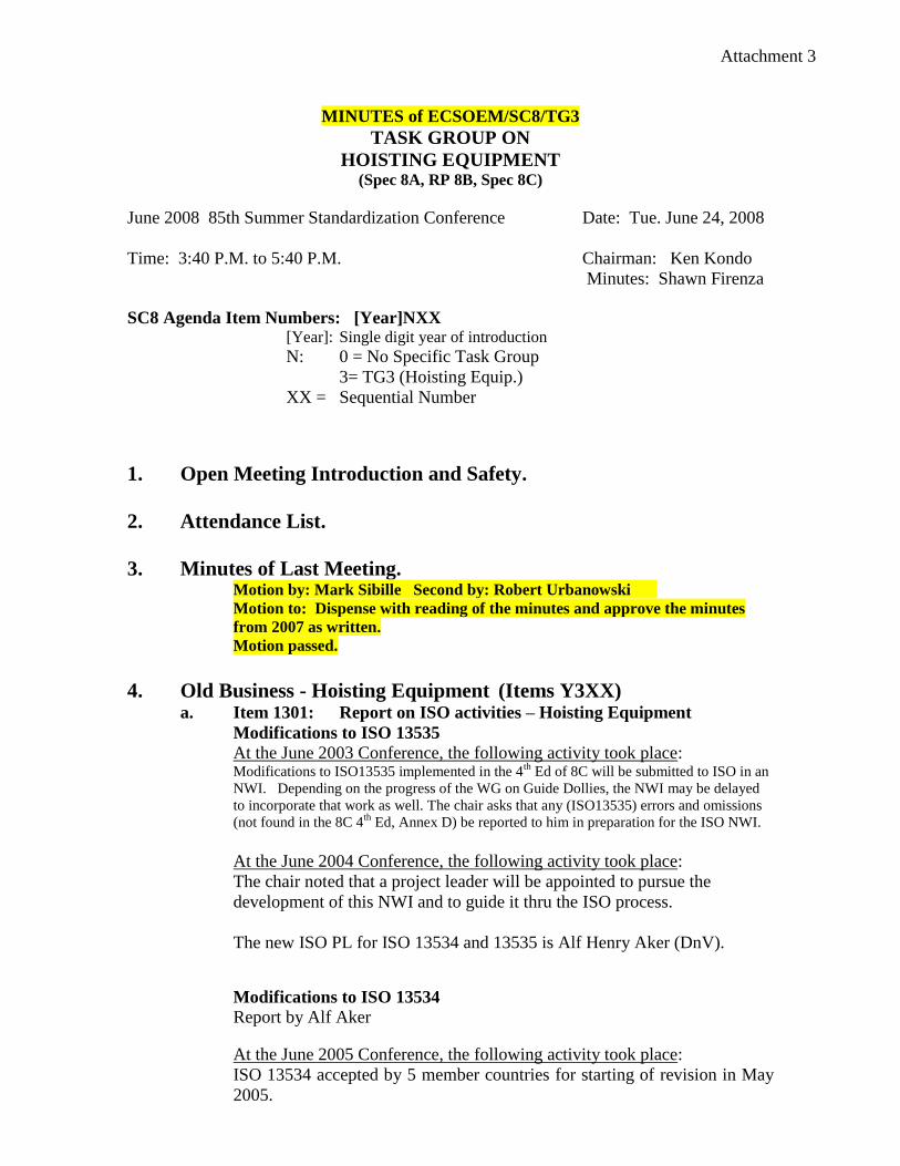
MINUTES of ECSOEM/SC8/TG3
TASK GROUP ON
HOISTING EQUIPMENT (Spec 8A, RP 8B, Spec 8C)
June 2008 85th Summer Standardization Conference Date: Tue. June 24, 2008
Time: 3:40 P.M. to 5:40 P.M. Chairman: Ken Kondo
Minutes: Shawn Firenza
SC8 Agenda Item Numbers: [Year]NXX [Year]: Single digit year of introduction
N: 0 = No Specific Task Group
3= TG3 (Hoisting Equip.)
XX = Sequential Number
1. Open Meeting Introduction and Safety.
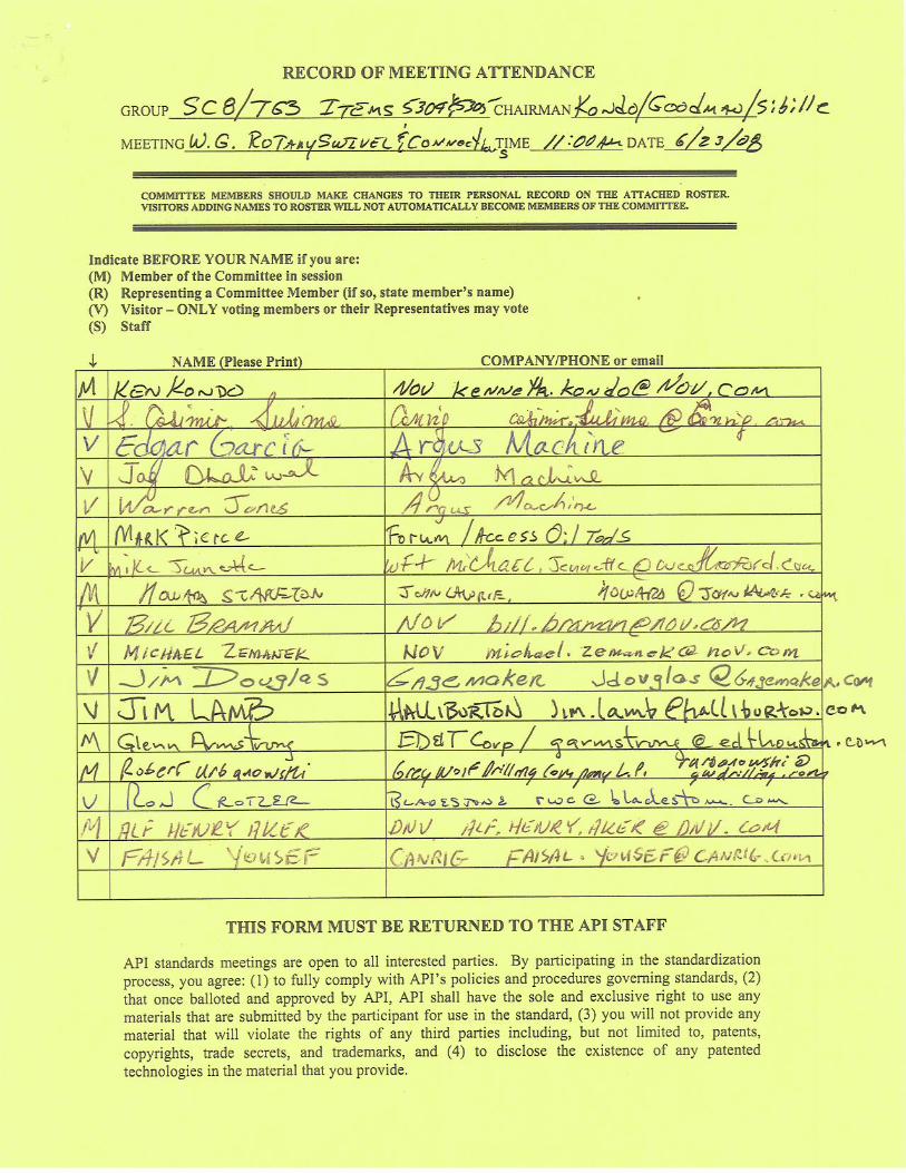
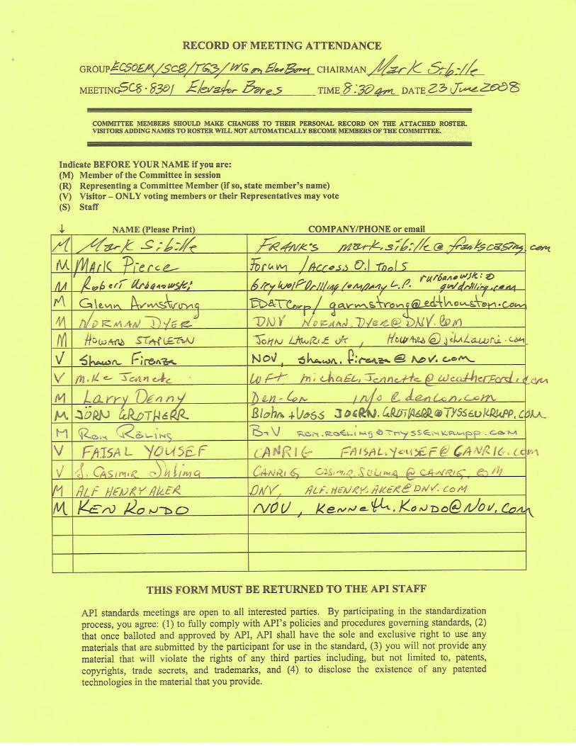
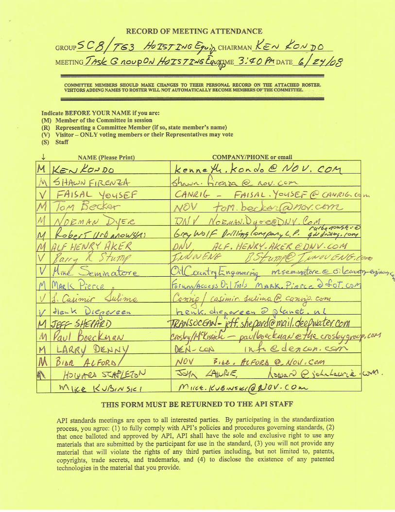
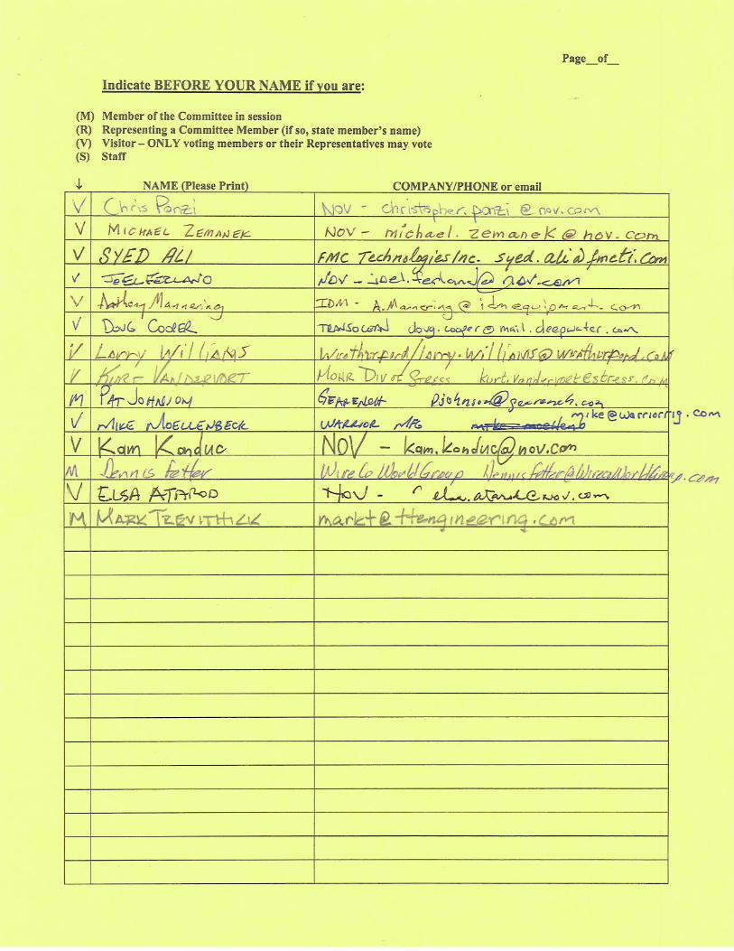
2. Attendance List.
3. Minutes of Last Meeting. Motion by: Mark Sibille Second by: Robert Urbanowski
Motion to: Dispense with reading of the minutes and approve the minutes
from 2007 as written.
Motion passed.
4. Old Business - Hoisting Equipment (Items Y3XX) a. Item 1301: Report on ISO activities – Hoisting Equipment
Modifications to ISO 13535
At the June 2003 Conference, the following activity took place: Modifications to ISO13535 implemented in the 4
th Ed of 8C will be submitted to ISO in an
NWI. Depending on the progress of the WG on Guide Dollies, the NWI may be delayed
to incorporate that work as well. The chair asks that any (ISO13535) errors and omissions
(not found in the 8C 4th
Ed, Annex D) be reported to him in preparation for the ISO NWI.
At the June 2004 Conference, the following activity took place:
The chair noted that a project leader will be appointed to pursue the
development of this NWI and to guide it thru the ISO process.
The new ISO PL for ISO 13534 and 13535 is Alf Henry Aker (DnV).
Modifications to ISO 13534
Report by Alf Aker
At the June 2005 Conference, the following activity took place:
ISO 13534 accepted by 5 member countries for starting of revision in May
2005.
Attachment 3
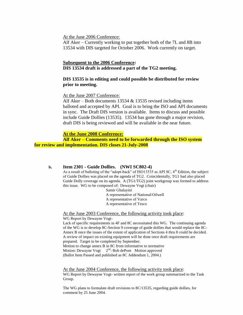
At the June 2006 Conference:
Alf Aker – Currently working to put together both of the 7L and 8B into
13534 with DIS targeted for October 2006. Work currently on target.
Subsequent to the 2006 Conference:
DIS 13534 draft is addressed a part of the TG2 meeting.
DIS 13535 is in editing and could possible be distributed for review
prior to meeting.
At the June 2007 Conference:
Alf Aker – Both documents 13534 & 13535 revised including items
balloted and accepted by API. Goal is to bring the ISO and API documents
in sync. The Draft DIS version is available. Items to discuss and possible
include Guide Dollies (13535). 13534 has gone through a major revision,
draft DIS is being reviewed and will be available in the near future.
At the June 2008 Conference:
Alf Aker – Comments need to be forwarded through the ISO system
for review and implementation. DIS closes 21-July-2008
b. Item 2301 - Guide Dollies. (NWI SC802-4) As a result of balloting of the “adopt-back” of ISO13535 as API 8C, 4
th Edition, the subject
of Guide Dollies was placed on the agenda of TG2. Coincidentally, TG1 had also placed
Guide Dolly coverage on its agenda. A (TG1/TG2) joint workgroup was formed to address
this issue. WG to be composed of: Dewayne Vogt (chair)
Samir Ghalayini
A representative of National/Oilwell
A representative of Varco
A representative of Tesco
At the June 2003 Conference, the following activity took place: WG Report by Dewayne Vogt-
Lack of specific requirements in 4F and 8C necessitated this WG. The continuing agenda
of the WG is to develop 8C-Section 9 coverage of guide dollies that would replace the 8C-
Annex B once the issues of the extent of application of Sections 4 thru 8 could be decided.
A review of impact on existing equipment will be done once draft requirements are
prepared. Target to be completed by September.
Motion to change annex B in 8C from informative to normative
Motion: Dewayne Vogt 2nd
: Bob dePont Motion approved
(Ballot Item Passed and published as 8C Addendum 1, 2004.)
At the June 2004 Conference, the following activity took place: WG Report by Dewayne Vogt- written report of the work group summarized to the Task
Group.
The WG plans to formulate draft revisions to 8C/13535, regarding guide dollies, for
comment by 25 June 2004.
After circulation by API staff, comments will be reviewed, the draft revised as necessary,
and submitted to API staff by the end of July for subsequent letter ballot.
LETTER BALLOT ITEM –upon submittal to staff.
At the June 2005 Conference, the following activity took place: Dewayne Vogt reported that work group members met 6/27/5. They are looking on
aligning safety factors with AISC requirements and will continue to work on the revision of
requirements for guide dollies in 8C. They will attempt to get a draft by mid-August 2005.
At the June 2006 Conference:
Some discussion occurred yesterday. Last work group report passed
around. A draft for letter ballot was due in mid-August 2005. Dewayne
Vogt is not available for comment.
To date, nothing has been submitted for letter ballot. Dewayne Vogt is not
available to continue as WG Chair. TG3 Chair to address the issue of
vacant WG chair.
Subsequent to the 2006 Conference:
TG3 Chair to appoint WG chair, and provided him with the names of the
WG members and a copy of the most recent draft. The WG is charged with
assembling a proposal for letter ballot.
At the June 2007 Conference:
Dewayne Vogt – Presented the proposed guide dolly section 9.17 (see draft).
Discussion –
Impact testing. Originally, all dollies were exempted; we felt it was necessary to include
for retractable dollies. Should impact be required for all dollies.
Sheppard – Dollies are generally held in place by nuts and bolts which won’t meet CVN
requirements. Most of the problems with Dollies have involved no secondary retention on
fasteners and general wear and tear and lack of inspection. No value in CVN on material.
Alf Aker – Appendix was created based on issues experienced in 1988. Loading was under
estimated, and dolly frame was deformed. Later experiences showed cracks in welded
construction on retractable dollies rather than fixed dollies. Horizontal acceleration is the
key issue for impact loading and fatigue, so it is not applicable to fixed dollies.
Sheppard – Only unusual loading occurs when the traveling equipment won’t self-align
with the vertical load.
Kubinski – What about addressing dropped objects.
Sheppard – This should address secondary retention of fasteners.
Sibille- Two years ago this was an agenda item, but it was not carried through on the
agenda.
Fatigue Life – Still a question about multiplier on service life.
Aker – Only called for the retract/extend forces to be considered in fatigue, so 3 x service
life is a safety factor. This has historically only been an issue on retractable dollies.
Dewayne Vogt to add wording to address secondary retention of fasteners for
guide dollies prior to the SC8 meeting tomorrow afternoon.
Ken Kondo to check previous minutes and agendas to review dropped object work
items.
Motion by: Mark Sibille Second by: Alf Aker
Motion to: Submit this draft to SC8 for consideration for letter ballot.
Motion passed.
Passed Letter Ballot with One (1) Negative Ballot. Negative comments are
not resolved and will be further discussed at the 2008 Calgary Conference.
At the June 2008 Conference: Review of negative comments from the letter ballot.
Jeff Sheppard (see ballot comments) - agreement was not reached with Jeff and
Larry Wells on the amplitude of these vibrations due to the age of the data and
analysis. Baker Hughes – Intech is the owner of the data.
Mark Sibille – We need to consider progression of ISO 13535 to determine if
there are any issues that need to be addressed immediately before the ISO DIS
proceeds while the API work group revisits the text in 8C.
Jeff Sheppard - willing to accept the DIS text as an interim solution until the work
group can resolve his comments. PLC III recognizes some of the other fatigue
modes.
Mark Sibille – Suggest that 13535 be allow to proceed, and the WG reconvenes.
Motion by: Mark Sibille Second by: Bide Alford
Motion to: Accept ISO 13535 DIS text in sections 9.17.1 to 9.17.2.4 as an
interim document, and send the guide dolly comments back to work group.
Motion Passed.
Jeff Sheppard - 9.17.2 Exemption of Guide Dollies from design verifications.
Can we use the wording that was balloted in Item 6301 to cover guide dollies.
Motion by: Jeff Sheppard Second by: no second
Motion to: Delete 9.17.3.
Motion died.
Motion by: Mark Sibille Second by: Faisal Yousef
Motion to: Accept the wording in ISO 13535 section 9.17.2.5 to 9.17.6 and
send the guide dolly comments back to work group.
Motion Passed.
Larry Wells with NOV was nominated to lead the new work group for guide
dollies. Faisal Yousef volunteered to serve on the new committee.
c. Item 3303: API 8C/ISO13535 – Hoisting Tool Contact Radii
This NWI proposed an extension of Table 6 – Hoisting tool contact-surface
radii, to include equipment with load ratings in excess of 1000 short tons.
At the June 2003 Conference, the following activity took place: Mark Sibille described the NWI proposal.
Discussion ensued as to whether 1400 is the appropriate upper limit.
Motion by Paul Boeckman Second by Bob dePont
Motion to: Form a work group to evaluate extending Table 6 above 1000 Tons.
Motion passed.
Work group members are Jens Lutzhoft, Joern Grotherr, Bob de Pont, Ken Kondo, and
Howard Stapleton. A work group leader will be selected later.
At the June 2004 Conference, the following activity took place: WG Report by Bob dePont. Work group has met and will develop a draft proposal by
September 1, 2004.
Motion to increase the scope of work group to include validation and design verification
for equipment from 1000 to 1500 short tons. Mark Sibille moved to approve, Howard
Stapleton seconded. Motion passed.
This is an on-going agenda item.
At the June 2005 Conference, the following activity took place: Bob dePont provided proposed C1, C2, D1, D2, G1, G2, H1 and H2 values to extend table for
higher loads. A completed proposed table to be completed and circulated by 8/1/05
At the June 2006 Conference:
Bob dePont presented proposal last year for contact radii. The proposal did
not pass due to manufacturers making products to different specs. He has
not been getting feedback from other manufacturers to allow development
of the table. 1250 ton equipment has to fit on 1000 ton equipment, but no
input has been coming from other manufacturers. Bob is still working to
get information to make a draft. Intent is to make the list from 1000 to 1250
and 1250 to 1500 ton.
Ken Kondo to provide a list of other contacts for Howard to obtain data.
Need to try to get some additional information and move this proposal
forward in the next 3 to 4 months.
Subsequent to the 2006 Conference:
Bob de Pont developed contact radii questionnaire. Attachment 1.
At the June 2007 Conference: Bob de Pont contact everyone, but received no information from the new contacts.
Mark (Access Oil Tools) request to be added to the work group.
Bob de Pont proposes to move this work to the NWI on 1250 ton equipment
Sibille: Rather than delay this another year, make another attempt to get the data. Establish
a deadline for the end of July for the 1000 ton radii data.
Those in attendance are to send data for radii to Bob de Pont at Bob
[email protected] by the end of July.
At the June 2008 Conference:
Bob de Pont did not receive feedback from all the users, so this item has
not progressed. Keep this item on the agenda.
d. Item 5302: Incorporating scope of API RP7L into ISO13534/API8B
(See TG2 agenda Item 5202.)
At the June 2005 Conference, the following activity took place: Discussed in TG2 meeting. Tabled pending results of TG2 work group on Item 5202.
At the June 2006 Conference:
Robert Urbanowksi – As discussed in the TG2 meeting, roll the scope of 7L
into the scope of 8B/ISO13534. (Refer to Agenda Item 1301.) Discussed
briefly whether or not to roll 7K items into 8C with no resolution.
At the June 2007 Conference:
Robert Urbanowski – Reported API putting together a comparison to ensure
that everything has been included. Draft DIS is still being worked on and
has not been sent for ISO approval yet.
Mark Sibille – Reported API staff is doing a document compare of the ISO
documents vs. the API specifications. ISO 13535 is the priority.
Information will be added to circulation as soon as it is available.
At the June 2008 Conference:
Alf Aker – In 13534, API 7L has formed the basis. Work Group on
BOP handling equipment has been added to the proposed revision of 13534.
e. Item 5304: 8C/Spec 7 Rotary Swivel Connection Demarcation
At the June 2005 Conference, the following activity took place: Re-evaluated Figure 11 to be and the demarcation of Spec 8C and Spec 7 more clearly
defined (and possibly moved so that the drillstem connection is shown to be Spec7). Also
should consider adding to Fig 11 to include a generic power swivel illustration. See Faisal
Yousef note below and the attached figure 11 from 8C.
-----Original Message----- From: Yousef, Faisal [mailto:[email protected]]
Sent: Wednesday, March 23, 2005 5:06 PM To: Brad Bellinger
Subject: API 8C
Brad,
Do the shear and tensile stresses in the stress relief groove of an API Pin (say 7 5/8" API PIN) have to meet API 8C safety factor or does it have to meet the safety factor of 1.0 as indicated in API Spec 7 for IBOP. In our application, the IBOP will connect to the bottom of our quill. The quill has a pin connection while the IBOP has a box connection. In one of the diagrams, you show that above the pin shoulder should meet API 8C and below that shoulder it should meet API Spec 7. Can you clarify what spec we should follow when doing calculations in the stress relief groove?
Thanks,
Faisal Yousef, P.E. Chief Mechanical Engineer Canrig Drilling Technology Limited
Tel: 281-259-3107
Fax: 281-259-8158
Mark Sibille, second by Howard Stapleton to modify the drawing and move
the Spec-8C/Spec-7 demarcation line up and add wording stating where the
line of demarcation is in relation to the tool joint. Motion passed 9 to 1.
At the June 2006 Conference:
No action has been taken on this issue, but we need to talk to Mark Sibille
about where this stands. Plan to have this ready for the next ballot.
Nothing has been done in the past year, because no one was appointed to
address it further. Request for a volunteer to work with Mark to clean this
up and have it move it forward, Bide Alford volunteered.
Subsequent to the 2006 Conference:
Bide Alford and Larry Foley collaborated on the two diagrams for Figure
11, to be balloted along with the new text for 9.9.5 per Agenda Item 5305.
At the June 2007 Conference:
Mark Sibille – Dividing lines moved and augmented with generic Power
Swivel.
Urbanowski – Left hand thread on the swivel diagram.
Mark Sibille – The threads will be corrected.
Items 5304 and 5305 were not sent out for Letter Ballot due to wording
issue. Wording to be further discussed at 2008 Calgary Conference.
At the June 2008 Conference: Howard Stapleton – Explanation of the revised drawing. Added callout 6 to two
lowest items on the drawing and called item 6 misc. drill stem components.
Motion by: Mark Sibille Second by: Robert Urbanowski
Motion to: Accept the proposed figure in place of the existing.
Motion Passed.
f. Item 5305: Rotary Shouldered Connections.
At the June 2005 Conference, the following activity took place:
Motion tabled by chairman so that the motion can be clarified in work group meeting
during a break. Norm Dyer proposed replacement of 9.9.5 with: “Rotary Shouldered Connections. Rotary swivel sub-connections
shall comply with the applicable requirements, including gauging and
marking, as specified in API Spec-7. Drill stem connections that carry
any load other than the drill stem load shall be rated in conformance
with API Spec-8C. Drill stem connections that carry only drill stem
load shall be designed in accordance with API Spec-7 and must have
minimum yield strength of 110,000 psi.”
Seconded by Jeff Shepard.
After rewriting, it was approved 9/0 Document Ballot
Subsequent to the June 2006 Conference:
Ballot of this item awaiting completion of the diagrams for Figure 11 (Ref.
Agenda Item 5304).
At the June 2007 Conference:
Alf Aker – To check whether this text is included in the DIS
Ken Kondo – Believe the text is in the DIS.
Motion by: Robert Urbanowski Second by: Mark Sibille
Motion to: Accept the Diagram and wording and recommend to SC8 for
letter ballot
Motion passed.
Items 5304 and 5305 were not sent out for Letter Ballot due to wording
issue. Wording too be further discussed at 2008 Calgary Conference.
At the June 2008 Conference: Glenn Armstrong– Started with text from Norm Dyer. Intent was to clarify the
difference in safety factors between API spec 7 and spec 8C and when to use
which safety factor.
Jeff Sheppard – What rotary shouldered connections do not see drill stem loads?
Mark Sibille – If a connection is required to carry other loads, then it needs to
meet 8C safety factors.
Robert Urbanowski – Should top drives have two ratings, one for the rotary
should connections, and one for the alternate load path.
Howard Stapleton– This section only addresses rotary shoulder connections.
Alf Aker – Do we need to include a comment on the figure from 5304 that is
operation specific?
Mark Sibille- The figure shows standard requirement for the RSC, the text adds
the requirement for 8C safety factor if seeing non-drill stem loads when that axial
load is suspended from the RSC.
Faisal Yousef – If the connection is good enough for the drill string, why would it
not be good enough for running casing?
Mark Sibille – Spec 7 is not adequate for top drive operations, but that is outside
of the scope of the group. The issue is the mis-match of safety factors between 8C
equipment hanging from a weaker connection.
Norm Dyer – This puts a manufacturer of power swivels at a distinct
disadvantage, and would force him to do something different than everyone else.
Mark Sibille- We are not changing the basic rating of the equipment, only the
rating when the tool is used in this alternate manor. All users of the RSC have the
same issue.
Motion by: Howard Stapleton Second by: Mark Sibille
Motion to: Send the revised wording to SC8 for letter ballot, but leave the
item on the agenda for further evaluation.
Motion passed.
g. Item 6301: API 8C 5.1 Design Verification Testing.
Norm Dyer/Brad Bellinger to introduce discussion on exemption for
verification testing of simple geometric forms. New Work Item submitted
by Norm Dyer.
At the June 2006 Conference:
NWI passed around for review
Discussion –
Norm Dyer – API 16F references API 8C, PSL2 stating that riser handling
tools should be designed in accordance with API 8C.
Current Proposal
In the third paragraph of subsection 5.1 General, eliminate –
“Equipment which, by virtue of its simple geometric form, permits
accurate stress analysis through calculations only shall be exempt
from design verification testing.”
Justification – This is not an auditable statement and is subject to
opinion related to the simplicity requirements. Also, the mention of
accuracy that infers that analysis of other parts of the equipment are
analyzed with less accurate methods, but, the required level of accuracy
is not described or implied.
Tom Becker – The intent for the sentence was for use with simple
component parts like nuts, bolts, pins in shear, components in pure tension,
etc. where simple calculations suffice.
Norm – This is being interpreted for use with complete pieces of equipment.
Also, there is some interpretation of analysis of pin/clevis connections.
Further discussion of riser handling tools and the specific offending
applications ensued.
Howard Stapleton – We have two paths. Either delete the paragraph or
reword the paragraph to limit the exemption to the original intent.
Motion: Move to accept the new work item with the change to reword the
paragraph in question rather than eliminating the paragraph.
Motion: Howard Stapleton 2nd
: Bob de Pont
Motion Passed
Ken Kondo asked Norm to establish a small group to work on the
rewording. Jeff Sheppard Volunteered
Subsequent to the 2006 Conference:
Norm Dyer and group formulated language for exemption to design
verification testing. Attachment II.
At the June 2007 Conference:
Norm Dyer – Explanation of wording
Robert Urbanowski – Does the term registered professional engineer work
globally?
Norm Dyer – The intent is that an exemption can not be made without an
independent review by a third party.
Mark Sibille – This issue was addressed in API 4G and we may be able to
use this wording.
Paul Meade-Clift – This wording issue is being addressed by ASME
Section VIII.
Sheppard – ISO 13534, “A Licensed Engineer or a Person who by
education, training, and experience can demonstrate the knowledge, skills,
and ability required to perform the work”
Norm Dyer – that wording is acceptable to the work group.
Remove the first 4 word from item d.
The new Item d reads:
“d. the exemption is reviewed and approved by a licensed engineer or a
person who by education, training, and experience can demonstrate the
knowledge and skills required or a recognized class society.”
Motion by: Robert Urbanowski Second by: Martin Jansen
Motion to: Recommend the revised wording to SC 8 for letter ballot with the
revised item “d.”
Motion Passed
Passed Letter Ballot with Two (2) Negative Ballots. Negative comments
are not resolved and will be further discussed at the 2008 Calgary
Conference.
At the June 2008 Conference: Paul Boeckman – Propose to remove item c from the requirements for exemption.
This requirement does not allow for any weldments to be excluded.
Jeff Sheppard – Suggest that what is balloted under 6301 and reference that in its
final form and state that reference in 9.17.2.
Tom Becker– Convoluted cannot be define
Norm Dyer- New proposed text to resolve the negative comments. Replace the 3
rd paragraph of 5.1 with the following
A Primary Load Carrying Component or Assembly may be exempted from design verification testing if it
meets all the following criteria:
a. The stressed cross section of the component is a simple geometric shape,
b. Stress analysis may be performed by means described in generally accepted classical design
literature,
c. The component is not joined to other primary load bearing components by welding,
d. The exemption is reviewed and approved by an individual independent of the group responsible for
the component design. The individual must be an engineer recognized by the local regulating
authority or a person who by education, training, and experience can demonstrate the knowledge
and skill required to perform the task.
Note:
a. Exemption from the testing should not be given for parts with complex shape that may induce stress
variations and concentrations
b. Components requiring advanced stress analysis methods are not candidates for the exemption
c. The components will usually be normal maintenance items.
Item a clarifies that the paragraph only applies to Primary Load Carrying
components or assemblies.
Item c further clarifies that it applies to welding to other primary load carrying
components. However, it eliminates the ability to create an assembly of “simple”
elements to work around the design verification testing.
Item d is an expansion of the existing item d to clarify who is allowed to review
and approve the exemption.
Note a changes “convoluted” to “complex”.
Based on discussion, we should remove item c.
Based on discussion, item d should be changed to state that the exemption and
justification should become part of the design file. API Q1 design review should
cover the independent review that is required.
Motion by: Paul Boeckman Second by: Mark Sibille
Motion to: Accept the modified wording with the following exceptions:
Remove item c. Change item d to “The Exemption is reviewed and approved
by an individual other than the person or persons responsible for the original
component design. The individual must be an engineer recognized by the local
regulating authority or a person who by education, training, and experience
can demonstrate the knowledge and skill required to perform the task.”
Motion failed.
Motion by: Tom Becker Second by: Jeff Sheppard
Motion to: Accept the modified wording with the following exceptions:
Remove item c. Change item d to “This Exemption is approved by an
individual other than the person or persons responsible for the original
component design.”
Motion Passed.
h. Item 7301: API 8B Guidance on Top Drive Alignment. Add top drive alignment criteria to the recommended practice. Fatigue
cracking and failures may occur if all drill string rotating components of
the top drive system are not in alignment.
New Work Item Proposal submitted by Tom Becker.
Attachment III.
At the June 2007 Conference:
Tom Becker – Explanation and presentation of the Attachment III. RP 8B
needs to at least notes regarding periodic inspection of alignment as a
maintenance issue.
Jeff Sheppard – Mis-alignment can be caused by a variety of issues (i.e.
derrick shimming, guide track alignment, ibops, main shaft connection,
etc.). The top drive manufacturer does not necessarily have control of all of
the components. The user also does not have a practical way to determine
the true runout. Reluctant to support additional requirements without a
practical means to verify the alignment.
Bill Braman – NOV recommends a specific tolerances in inches to well
center.
Craig Weems – Manufactures recommendation has more to do with
preservation of the machinery rather than the impact on the tubular
connections. Using a pipe as a plumb bomb does not take into account the
deviation of the hole and the drill string.
Jeff Sheppard – We need to be able to determine the alignment throughout
the derrick regardless of the hole. What is the bench mark? Need a work
group with input from TG1.
Norm Dyer – Is it possible that the power swivel stem , ibops, etc are not in
alignment to each other? Or is this a matter of keeping the whole assembly
in line to the well center? This is an age old problem going back to swivel
connections to the Kelly.
New Work Item Accepted and Work Group developed
Chair - Bill Bramen
Work Group - Jeff Sheppard, Bob Sheti, Faisal Youseff, suggestion to
solicit SC5 drill stem elements, and rep from Maritime Hydraulics.
At the June 2008 Conference: Bill Braman – Team met in December 2007 and drafted the document handed out
during the meeting. First paragraph is justification for the document.
Comments – What is the definition of regular basis for inspection? RP 8B leave
this determination up to the manufacturer.
-This seems to say that the first signs of misalignment are a crack main shaft, and
then you call in the experts. This does not tell anyone how to measure
misalignment and determine whether or not the misalignment is critical. There is
not preventative measures to verify the alignment prior to cracks. An example is
RP 4G guidance on acceptable deflections which gives guidance, but does not
allow everything.
- Previous inspections show crack in second or third thread that can be found with
eddy current inspection. Still no inspection techniques to find fatigue prior to
failure.
-This document is to be added to RP 8B. There is no statement here to follow
manufacturer recommended inspections, but that is covered in RP 8B in other
sections.
- Add the words “herein RP8B” in solutions section.
- There is no guidance on “how careful” an operator needs to be. Should we
include some guidance on alignment such as the chart used in other sections. This
should also send the user back to the original manufacturer.
- At least guidance on who to go to for what issues.
Keep this item on the agenda. The work group should continue.
i. TG2 Item 7302: Addition of 1250-Ton Load Rating. Note- Some portions of this NWI may over-lap existing Agenda Item 3303.
New Work Item Proposed by Tom Becker.
Attachment IV.
At the June 2007 Conference:
This item redesignated as 7302
Tom Becker – Explanation of the New Work Item request.
Suggest Larry Wells and Bob de Pont and work group leaders due to their
involvement in 1250 ton design
Mark Sibille- Are we talking about changing design safety factor or dvt
requirement?
Tom Becker – Reducing safety factor is not out of the question, dvt load
reductions coupled with finite element analysis is also a possibility.
Joern Grotiaerr - Propose to increase the work item up to 1500 ton rating
Motion by: Mark Sibille Second by: Tom Becker
Motion to: Accept the NWI and establish work group
Motion Passed
Work Group Chairs: Bob de Pont & Larry Wells
Work Group: Alf Aker, Ron Roling, Kurt Vandervort, Faisel Yousef, Mark
Pierce, Tom Becker, & Anthony Mannering.
At the June 2008 Conference:
Leave on the agenda
j. TG2 Item 7202: Alternative Method for Selection of QTC
Specimen Locations. NWI proposed by Mark Sibille, providing for alternative method of
determining the locations for removal of test specimens from wrought
bars for which the current (“1/4T envelope”) requirements places the
specimens in volumes that are not representative of the finished parts.
(In some cases, the “1/4 T Envelope” is in the volume of bar that is
machined away in manufacture of the finished parts.)
Attachment V.
At the June 2007 Conference:
Robert Urbanowski – Explanation of TG2 status. Ballot passed for 7K.
Motion by: Mark Sibille Second by: Robert Urbanowski
Motion to: Recommend the proposed wording with an example to SC 8 for
letter ballot for API 8C
Motion Passed
Passed Letter Ballot with No Comments. To Be Publish
At the June 2008 Conference:
Remove from the agenda
k. NWI 7303: Use of Nylon Sheaves for Sandline Application Ken Grier requests a work group be established to work on this issue.
At the June 2007 Conference:
Motion by:Mark Sibille Second by: Martin Jansen
Motion to: Accept the NWI proposed as 7303 and establish the work group
Motion Passed
Work Group Chair: Ken Grier
Work Group: Cleon Shelton, Norm Dyer, Pat Johnson, Dennis Fetter
At the June 2008 Conference: Nothing to report at this time. Leave on the agenda
l. NWI 7304: Dropped Object
At the June 2007 Conference: Mike Kubinski – Do we want to include some statement regarding secondary
retention and dropped objects?
Mark Sibille – Ken Kondo needs to check the records to see if this was dropped
from the agenda.
Ken Kondo – This needs to be addressed and put forth as a NWI
Motion by: Mark Sibille Second by: Jeff Sheppard
Motion to: Establish a new work item to address dropped objects for
overhead equipment. This new work item will encompass any previous work
items that may have been lost from the agenda. Item 7304
Motion Passed
Work Group Chair: Mike Kubinski
Work Group: Shawn Firenza, Jeff Sheppard, Pat Johnson, Bill Bramen,
Norm Dyer, Faisel Yousef, Paul Boeckman.
At the June 2008 Conference: Mike Kubinski – Presented what was agreed in the work group
Motion by: Faisal Yousef Second by: Pat Johnson
Motion to: Accept the proposed wording for dropped objects and send for
letter ballot.
Motion Passed.
5. New Business – Hoisting Equipment (Items 73XX)
a. Item 8301: Bore Size and Max Wear Square Shouldered
Elevators Establish a set of mathematical formulae to calculate the appropriate bore size for
newly manufactured square shouldered elevators (API 8C/ISO13535) and a
separate set of formulae to establish the maximum allowable wear in the bore of an
elevator in use (API 8B/ISO13534).
Develop required text and table changes to include these in API 8C and API 8B,
and for forwarding to the ISO PL for 13535 and 13534.
See NWI 8301 Attachment for proposed changes.
New Work Item Proposed by Mark Sibille.
Committee Volunteers: Bob dePont, Joern Grotherr, Mark Pierce, and Howard
Stapleton
At the June 2008 Conference: Mark Sibille – Explanation of the work product. Need to add the appropriate
illustrations for the localized wear allowances. Localized wear allowance came
from user experience, manufacturer representation, and common blending
recommendations.
- API standards major contribution to safe operation is standardization of
dimensions. Why then are we getting rid of the standard API pipe size table
recommendations? The intent of the equations is not to replace API standard
sizes; it is to eliminate the need to amend the table based on non-standard pipe
sizes.
- Industry Trend is that pipe is not API standard sizes.
- Are we creating difficulty for people by eliminating the table for standard pipe
sizes? The table could be upgrade with the formulas and then reference the
formulas for non-standard sizes.
- Metric conversion for allowable needs to be corrected
- Current specification has some given information for allowable clearance. The
new method dramatically increases the allowable for some cases. Have there been
any calculations made to justify the difference? No, the work group has not seen
that dramatic difference. Clarification, this is a question on the wear allowance?
New tools have to allow some wear. The new tolerance can not be the same as the
allowable max diameter. Practically, in service tools have to have a wear
allowance. The manufacturing data provided was all greater than the
recommendations on wear allowance, so the proposed allowables are more
conservative than the manufacturing recommendations.
- The new equations give a nominal bore and based on the tolerance a largest bore
for new equipment. Is there any new calculation maximum bore that is higher the
existing table plus the tolerance? There are a few areas with a difference (minimal
difference) between the old table and the new calculations.
Motion by: Mark Pierce Second by: Larry Denny
Motion to: Accept the proposed wording from the work group with revision
to note 3 “Nominal Diameter x 0.25” strike from 7mm to end of ) for letter
ballot.
Motion Passed.
New Wording for Localized Wear Localized Wear Allowances: When the load shoulder bore diameter is measured, if localized portions of the bore are found to measure larger than DMA (computed above), the bore may still be accepted if all of the following conditions are met:
1. The depth of wear, grinding, or other damage in localized portion(s) of the
bore must not exceed 3.2 mm (1/8 in); 2. The surface of a localized wear, grinding, or other damage, must be
blended back to the adjacent bore surfaces with a transition not less than 3 to 1 (length to depth);
3. After blending, the total length (measured around the bore surface) of all such areas of localized wear, grinding, etc., including the transitions to the bore surface, must not exceed the Nominal Diameter x 0.25 in length.
b. Item 8001: SR1 – Expressed exemption of SR1 marking
requirement for equipment which 8.6.1 requires proof load
testing (i.e. SR1 is redundant) Expressly relieve the mfr of the obligation to mark SR1 on equipment that is
normally proof load tested to fulfill the requirements of 8.6.1, for which SR1 is
redundant.
Proposed:
ADD to (8C & 7K) Annex A2:
Marking “SR1” is not required on equipment for which proof load testing is
normally required under Clause 8 or Clause 9 of this standard.
New Work Item Proposed by Bob dePont.
At the June 2008 Conference:
Mark Sibille – Explanation SR1 requires the tool to be marked with SR1. For
products already requiring proof load testing should not require the marking of
SR1. The goal is to revise Annex A2.
Motion by: Mark Sibille Second by: Robert Urbanowski
Motion to: Send the proposed wording to SC8 for letter ballot
Motion Passed.
c. Item 8002: Exempt from proof load testing, replacement hinge
and latch pins made from wrought material. While design verification testing is of great importance, production proof load
testing of the hinge or latch pins (if made of wrought material) is unnecessary,
except where necessary to test the tool body (particularly for tool bodies
manufactured from castings). In the case of replacement parts, proof load testing
of replacement pins has an unjustifiable negative impact on schedule and cost of
repair of equipment in the field. (However, if hinge or latch bores are re-
machined, RP7L and RP8B would still require proof load testing because of the
remanufacturing of the bodies, even though this change would technically exempt
the replacement hinge or latch pins.)
Proposed:
ADD to API 7K, 9.5.6, and to API 8C, 9.8.3:
Replacement Hinge Pins or Latch Pins manufactured from wrought material are
exempt from proof load testing requirements.
New Work Item Proposed by Bob dePont.
Committee Volunteers: Mark Sibille
At the June 2008 Conference: Mark Sibille – Currently, the document could be interpreted to requiring proof load
tests of hinge pins and latch pins. This does not add value in a wrought pin.
Replacement of a hinge pin may become a cycle of damaging the pin to allow for
load testing and removing the pin for inspection. Under repair no load test should
be required. For remanufacture, the load testing would still apply.
- If it is of no value to proof load test for replacement hinge pins, then why don’t
we exclude them from load testing all together.
Motion by: Tom Becker Second by: Mark Sibille
Motion to: Exempt wrought hinge pins from load testing requirements in API
8C
Motion Passed.
The original reference was to 9.8.3 for Slip Type Elevators. Should this be moved
up to 9.8 to include all elevators.
Motion by: Tom Becker Second by: Mark Sibille
Motion to: Revise previous motion to move the exemption to section 9.8
Motion Passed.
d. Item 8202: NDE Inspections – ASME Methods Clarification of
Wording. Changes to 8.4.8.1 and 8.4.9.2.3 to update/correct the references to ASME V.
At the June 2008 Conference: Mark Sibille – This is applicable to TG 3. TG 2 chair was just more diligent about
getting it added to the agenda.
Robert Urbanowski – This is an editorial change to correct the reference to ASME
V.
-This was triggered by an auditor inquiry where the wrong article reference was
found.
-Need to correct proposal for 8.4.9.2.3 to leave the PSL references the same as
existing text.
Motion by: Mark Sibille Second by: Bill Braman
Motion to: Accept the proposal with the addition of the PSL statements for
8.4.9.2.3
Motion Passed.
6. Adjournment. – (at 7:32PM) Motion by: Paul Boeckman Second by: Larry Denny
Motion to: Motion to adjourn
Motion Passed