Embed Size (px)
Citation preview

1
Overview of the NPDGamma Experiment
at theFundamental Neutron Physics Beamline
Geoff GreeneUT/ORNL

2
Overview
• FNPB Beamline
• NPDGamma Experimental Layout
• Radiological Shielding
• Magnetic Shielding
• Issues and Concerns

3
Preliminary Design Review Charge
• Have the hazards been completely identified and accurately classified?
• Is the design reasonable and does it adequately address identified hazards?
• In particular, is the conceptual design for the liquid hydrogen system (target, control system, vent stack) capable of leading to an acceptable final design of the system?
• Are the proposed operational parameters and physical characteristics of the hydrogen target system appropriate for safe operation?
• Are other aspects of the experiment reasonable and amenable to safe operation?

4
FNPB “Upstream” Beamline Components
Shutter Insert
Core Vessel InsertShutter Gate
Core VesselFlange
STARTING POINT
neutrons

5
Cold Beamline
– Guide from 5.5 m to 15 m– Bender out to 7.5 m (R=117 m)
Line of sight ends before 2ndary shutter– 4 chopper housings– Monochromator housing– Secondary Shutter– Beam Monitor & Beam Stop
FNPB Cold Neutron Beamline

6
Monolith Shielding
FNPB Cold Neutron Beamline

7
FNP DESIGN OVERVIEW

8
FNPB Construction Status 6/07
Project is currently on schedule

9
FNPB Shield Wall

10
The FNPB Cold Beamline design is essentially complete.
Remaining tasks are completion of shielding enclosure detailed design, PPS, and utilities layout.
We are NOT explicitly asking for a review of these components.
FNPB Cold Beamline Status

11
The NPDGamma Experiment
Supermirror polarizer
FNPB guide
CsI Detector Array
Liquid H2 Target
H2 Vent Line
Beam Stop
Magnetic Field Coils
Magnetic Shielding
H2 Manifold Enclosure

12
The NPDGamma Experiment – Vent System

13
The NPDGamma Experiment – Shield Roof and Mezzanine
14
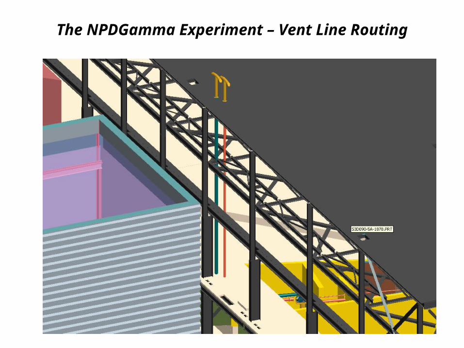
The NPDGamma Experiment – Vent Line Routing

15
Radiological Shielding
NOTE: Because of curved guide and use of 6Li collimation, dose rates are totally dominated by photons by
cold neutron capture.*
Shielding enclosure:
18” Concrete shared wall with FP 129” Concrete wall on FP 14 side9” Concrete roof
Enclosure is lined with Steel (up to 2” in places)
Additional “temporary” shielding blocks are placed on FP14 of Wall
*This is validated by MCNPX simulaltions.

16
MCNPX Radiation Simulations

17
MCNPX Radiation Simulations

18
Magnetic Fields
The NPDGamma magnetic field is low (10 Gauss) but occupies a large volume. The shielding enclosure is lined with 0.25”-0.75” of 1010 steel to act as a flux return. This also serves to provide magnetic shielding and to confine stray magnetic fields. We used commercial magnetic FEA software (OPERA3D) to model our magnetic field arrangement.
Facility requirements call for magnetic field to be less
than 50mGauss at the boundary of adjacent beamlines

19
Stray Magnetic Fields -SummaryThe NPDGamma external magnetic field is below the facility required level at the FP12 boundary and the FP15 boundary. It slightly exceeds the required level at the FP14 boundary. This is acceptable to FP14 beamline responsibles.
E
F
90.8
152.2
348
359.2
Coils
Magnetic shield
Z182.68
Concrete wall
Concrete wall
1
X331.65
788.72
303.83
30.5
30.5
A
B
440.72
133
225
2
FP 12 side
FP 14 side

20
Other Issues
A detailed hazard screening (next presentation) has identified the liquid Hydrogen target as the only “exceptional” operational issue. All other hazards are similar to those encountered on other SNS instruments.
The details of the LH2 target and vent system are the subject of the third presentation.

21
The NPDGamma Experiment
Supermirror polarizer
FNPB guide
CsI Detector Array
Liquid H2 Target
H2 Vent Line
Beam Stop
Magnetic Field Coils
Magnetic Shielding
H2 Manifold Enclosure
22
End of Presentation